Exoskeleton Walking Suits Explained
1. What Walking Suits Are and How They Work
1.1 Defining Exoskeleton Walking Suits and Their Intended Use
An exoskeleton walking suit is a wearable robotic system designed to assist a person’s leg motion during walking. The key word is assist: the suit provides mechanical support or guidance so the user can move with less effort, more stability, or both. It is not a replacement for the user’s balance system; it is a tool that works alongside it.
What “Walking Suit” Means in Practice
Most walking suits focus on lower-limb assistance, typically at the hips, knees, and/or ankles. The suit’s job is to translate the user’s intent and body motion into controlled forces or torques at the joints. That translation can be based on different signals, such as joint angles, foot contact timing, or whole-body posture.
A useful way to define the intended use is to separate three goals:
- Mobility support: helping someone stand, walk, or walk longer with less physical strain.
- Gait training support: encouraging a safer or more repeatable stepping pattern during rehabilitation.
- Human augmentation support: reducing the cost of walking tasks for people who can already walk, such as carrying loads or maintaining endurance.
In real deployments, these goals often overlap, but the design choices differ. A system aimed at rehabilitation usually emphasizes repeatability and safety constraints. A system aimed at mobility support emphasizes comfort, ease of donning, and predictable assistance.
Intended Use Depends on Who and What
“Intended use” is not just a marketing phrase; it is a boundary around where the suit is expected to work reliably. That boundary is shaped by user needs and environment.
Consider three common user profiles:
- People with weakness or reduced endurance: the suit should reduce the effort needed to generate stepping forces.
- People with impaired control or coordination: the suit should help timing and joint motion so steps are more consistent.
- People with balance limitations: the suit should support stability without fighting the user’s corrective movements.
Now consider environments:
- Level ground is the baseline case for most systems.
- Uneven surfaces require more robust sensing and conservative assistance.
- Transfers like sit-to-stand demand different control behavior than steady walking.
A suit’s intended use statement should match these realities. If it is designed and validated for level-ground walking, using it as a general “everywhere” solution is a mismatch.
How Assistance Is Typically Delivered
Exoskeleton walking suits generally provide assistance in one or more of these ways:
- Torque assistance: the suit applies rotational help at a joint, such as assisting knee extension during stance.
- Trajectory guidance: the suit encourages a desired joint angle path, often with compliance so the user can still move naturally.
- Resistance or damping: the suit can reduce unwanted motion, such as controlling knee flexion speed to improve stability.
The “right” method depends on the user’s impairment. For example, if a user can initiate steps but tires quickly, torque assistance may be more appropriate than heavy guidance.
Mind Map: Defining Intended Use
Example: Matching a Suit to a Need
Example 1: Endurance support on level ground A user can walk but stops after a short distance due to fatigue. The suit’s intended use is steady walking on level ground. The assistance strategy focuses on reducing peak joint effort during stance and swing, with smooth transitions so the user does not feel “yanked” into a rhythm.
Example 2: Training consistency during rehabilitation A clinic wants repeatable stepping patterns for practice sessions. The intended use includes guided walking sessions under supervision. The suit emphasizes consistent timing cues and conservative safety behavior, so the user can practice without the system introducing large, unpredictable forces.
Example 3: Balance-limited walking A user has difficulty maintaining stability during transitions between steps. The intended use is walking with close supervision and conservative assistance. The suit prioritizes stability support and compliant behavior, allowing the user to make corrective motions rather than locking them into a fixed gait.
In each example, the defining feature is not the hardware alone. It is the pairing of assistance behavior with a specific user need and a specific walking context.
1.2 Core Components and How Motion Is Translated to Assistance
A walking suit turns body motion into assistance by combining four things: sensing, estimating what the user is doing, deciding what help to apply, and producing forces at the right joints. The trick is not just “detect motion,” but “detect the right part of motion at the right time,” then apply torque or guidance without fighting the user.
The sensing layer
Most suits use a mix of sensors so they can tell the difference between “the user is moving” and “the user is in a specific gait phase.” Common inputs include:
- Inertial measurement units on the shins, thighs, or pelvis to track orientation and angular velocity.
- Joint encoders to measure relative angles at the hip or knee.
- Force or pressure sensing in footplates or insoles to detect heel strike, mid-stance, and toe-off.
- Optional electromyography to infer muscle activation when the goal is more personalized assistance.
A practical example: if the suit only used an IMU, it might confuse a slow turn with a normal step. Adding foot pressure helps because heel strike and toe-off create repeatable pressure patterns.
The estimation layer
Raw sensor signals are noisy, and human motion is not perfectly periodic. Estimation converts measurements into a stable “state” the controller can use. Typical estimated variables include:
- Gait phase such as stance vs. swing.
- Step timing like approximate time since last heel strike.
- Joint angles and angular velocities filtered to reduce jitter.
- Posture cues such as trunk lean or pelvis tilt.
A simple way to think about it: sensors answer “what is happening right now,” while estimation answers “what does this likely mean for the next few moments.”
Example: during swing, the knee needs help to clear the foot. If estimation delays the phase change by even a fraction of a second, the suit may apply assistance too early, causing awkward knee timing.
The decision layer
Once the suit knows the gait phase and joint state, it chooses an assistance strategy. This is where “translation to assistance” becomes concrete.
Common decision inputs:
- User intent cues inferred from motion patterns, such as walking speed or step cadence.
- Assist-as-needed thresholds that scale help based on how much the user is already doing.
- Mode selection for walking, sit-to-stand, or stair-like stepping.
Example: if the user is already generating strong knee extension during stance, the suit can reduce torque demand to avoid pushing against the user’s effort.
The actuation layer
Actuators convert electrical commands into mechanical output. For walking suits, the goal is usually to apply torque at a hip or knee, or to provide guidance that constrains motion in a helpful way.
Key hardware choices:
- Motor and transmission sized for the required torque at the joint.
- Brakes or clutches for holding position or preventing runaway motion.
- Series elastic elements in some designs to store and release energy smoothly.
A concrete example: knee assistance during swing often benefits from compliant behavior. If the actuator is too stiff, small timing errors can feel like the suit “yanks” the leg. Compliance can make the same correction feel more like support.
The control layer that ties it together
Control is the glue between estimation and actuation. A typical loop uses feedback so the suit corrects errors continuously.
- Reference generation creates a target trajectory or target torque profile for the current gait phase.
- Feedback regulation compares measured joint angle/velocity (and sometimes forces) to the reference.
- Safety constraints cap torque, limit speed, and enforce safe behavior when sensors disagree.
Example: suppose the suit expects knee flexion to increase during early swing. If the measured knee angle lags behind, the controller can increase assistance within limits. If the lag is caused by a sensor fault, safety constraints prevent the suit from reacting blindly.
Mind Map: Motion to Assistance Pipeline
Example: Translating One Step into Assistance
- Heel strike detected: foot pressure rises sharply and shin IMU orientation matches a stance pattern.
- Phase switches to stance: estimation updates the gait phase state and resets step timing.
- Decision selects stance support: the suit targets a knee/hip torque profile that helps stabilize without forcing a stride.
- Control regulates to targets: measured joint angles are compared to the reference, and torque commands are adjusted.
- Toe-off detected: pressure shifts from heel to forefoot and then drops, signaling transition.
- Phase switches to swing: the suit shifts to swing assistance, often emphasizing knee flexion and foot clearance.
- Safety monitors consistency: if sensor readings conflict, assistance is reduced and the suit holds a safe behavior.
Example: What Changes When the User Slows Down
When cadence drops, the suit must avoid applying the same timing as before. Estimation updates step timing, decision logic scales assistance based on effort, and control retimes the reference so the knee and hip targets align with the new gait rhythm. The user experiences this as support that stays “in sync” rather than as a fixed pattern that ignores how they’re walking.
The “right joint, right moment” principle
A walking suit succeeds when assistance is applied where it helps and when it helps. That requires the pipeline above to be coherent: sensing must be reliable, estimation must be stable, decision must match the user’s current task, and actuation must respond within safe limits. When any one layer is off, the result is usually timing errors, awkward joint behavior, or unnecessary effort from the user.
1.3 Actuation Types and What They Mean for Real-World Gait Support
Actuation is the “muscle” of a walking suit: it converts control commands into forces and torques at joints. Different actuation types change what the suit can do well, what it struggles with, and how it feels to the user. In practice, the best choice depends on whether you need smooth assistance, strong torque at specific joints, or reliable foot placement with minimal user effort.
Motor-Driven Joint Torque Assistance
Motor-driven systems apply torque directly at a joint through gearboxes and linkages. When the controller commands a knee or hip torque profile, the motor produces the corresponding rotational effect.
Real-world meaning: torque assistance can be precise and repeatable, which helps when the goal is to reduce the user’s effort during stance or to support a weak joint during push-off. A common example is assisting knee extension during late stance so the user can progress into swing without collapsing.
Easy example: If a user’s knee buckles near the end of stance, the suit can detect the phase and apply a modest extension torque for a short window. The user still initiates the step, but the suit reduces the “last stretch” that would otherwise require extra strength.
Tradeoff: torque systems can feel “active” because they are always capable of producing force. That’s why good control uses smooth ramps and limits, and why fit alignment matters: if the joint center is off, the torque may act in the wrong direction.
Cable and Bowden Mechanisms
Cable-based actuation routes force through cables and pulleys. The motor tension changes the cable length, which pulls on a linkage attached to the limb.
Real-world meaning: cables are good at transmitting force over distance and can package actuators away from the most sensitive skin areas. They also tend to be mechanically simple and robust.
Easy example: For ankle support, a cable can pull the foot into dorsiflexion during swing to reduce foot drop. The user’s leg swings forward, and the suit ensures the toes clear the ground.
Tradeoff: cables introduce compliance and friction. That means the same motor command may not produce exactly the same torque under different loads, so the controller often needs careful calibration and conservative force limits.
Series Elastic Actuation
Series elastic actuation places an elastic element between the motor and the output. Instead of sending force instantly, the system stores and releases energy through a spring.
Real-world meaning: elasticity can improve comfort and safety because it limits sudden force spikes. It also helps the controller regulate force rather than just position.
Easy example: During early stance, a user may land with variable impact. With series elasticity, the spring compresses slightly, smoothing the force transfer. The suit can then assist push-off without feeling like it “kicks” the joint.
Tradeoff: the spring adds delay and reduces responsiveness at very high frequencies. That’s usually fine for gait assistance, but it matters if the suit must react to fast perturbations.
Pneumatic and Hydraulic Actuation
Pneumatic systems use compressed air (often through bladders or cylinders), while hydraulic systems use pressurized fluid. Both can generate force with good power-to-weight characteristics.
Real-world meaning: these actuators can be effective for large, distributed support, especially when integrated into cuffs or soft interfaces. They can also provide a natural “give” due to fluid compressibility.
Easy example: A pneumatic hip assist can provide a supportive extension force during stance while allowing some compliance when the user shifts weight. The user experiences less rigid coupling than with a stiff joint actuator.
Tradeoff: pressure control and leakage management are practical concerns. The suit may require more careful monitoring to ensure consistent assistance across sessions.
Passive and Hybrid Assistance
Passive elements include springs, clutches, and mechanical linkages that provide assistance without continuous motor power. Hybrid systems combine passive components with active control.
Real-world meaning: passive assistance can reduce the energy the motor must supply and can make the suit feel more “automatic” for certain gait patterns.
Easy example: A spring-assisted ankle mechanism can store energy during dorsiflexion and release it during push-off. The motor then only tops up or corrects when the user’s gait deviates.
Tradeoff: passive assistance is less adaptable. If the user’s stride length or timing changes, the passive contribution may not match perfectly, so hybrid control is often used to correct the mismatch.
Mind Map: Actuation Types and Gait Support Outcomes
Case Study: Choosing Actuation for Foot Drop Support
A user with foot drop struggles to clear the ground during swing. The suit must help dorsiflex at the right time without forcing the user’s hip to compensate.
A cable-based ankle dorsiflexion mechanism is a common fit because it can pull the foot upward during swing with a compact actuator location. If the user also experiences discomfort from sudden force changes, series elasticity can be added so the dorsiflexion force ramps smoothly as the foot approaches the ground.
In both designs, the key is timing: the controller uses gait phase detection to apply assistance during swing and relax it during stance. That prevents the suit from fighting the user’s push-off and keeps the assistance feeling like support rather than resistance.
1.4 Control Loops and Feedback Signals Used During Walking
A walking suit needs to decide, repeatedly and quickly, how much help to apply at each joint. That decision comes from control loops—small cycles that read sensors, estimate what the body is doing, compute an assistance command, and then check whether the result is safe and sensible. The “feedback signals” are the measurements that tell the controller whether it is on track.
Control Loop Basics
Most walking-suit controllers run multiple loops at different speeds. A fast loop handles motor commands and immediate safety checks, while a slower loop updates higher-level state like gait phase or walking intent.
A practical way to think about it:
- Inner loop: keeps joint torque or position close to the requested value.
- Middle loop: shapes the motion so it feels compliant rather than rigid.
- Outer loop: decides when to assist, how strongly, and which joints should be active.
A key best practice is to ensure each loop has a clear job. If the inner loop tries to guess gait phase, the system can become inconsistent when the outer loop changes its mind.
Feedback Signals You Actually Use
Walking suits rely on feedback that falls into four categories.
-
Kinematics feedback: joint angles and angular velocities.
- Example: If the knee flexes too slowly during swing, the controller can reduce assistance that would otherwise “push” the leg into an awkward angle.
-
Forces and pressures: torque estimates, motor current, and pressure distribution on contact points.
- Example: If pressure spikes under a footplate during stance, the controller can lower assistance to avoid overloading the user’s limb.
-
Body orientation and motion: inertial measurements from IMUs.
- Example: If the trunk tilts unexpectedly, the controller can adjust hip assistance to help maintain balance rather than continuing a plan that assumes upright posture.
-
Timing signals: gait phase indicators derived from sensor patterns.
- Example: If the system mislabels heel strike as mid-stance, it may apply swing support too early; correcting phase timing prevents that.
A useful rule of thumb: feedback should be tied to the physical effect you want. If you want smoother knee motion, joint angle and velocity matter more than a single “walking yes/no” signal.
Gait Phase Detection and Step Timing
Many suits use gait phase detection to decide when to assist. A common approach is to classify phases using patterns from foot contact sensors, IMUs, and sometimes joint kinematics.
Concrete example: stance vs. swing
- Foot contact sensor indicates when the foot is loaded.
- IMU on the shank shows whether the shank is moving forward like swing.
- Knee angle trajectory helps confirm the transition.
Best practice: add hysteresis and minimum dwell times. Without it, the controller can chatter—rapidly switching modes when signals hover near a threshold.
Assistance Computation with Feedback
Once the controller knows the phase and the user’s current state, it computes an assistance command. Two common strategies are:
-
Impedance-like behavior: the suit behaves like a controllable spring-damper around a target trajectory.
- Example: During swing, the suit can aim to reduce foot drop by applying torque proportional to the difference between desired and measured ankle angle, while damping oscillations using measured angular velocity.
-
Admittance-like behavior: the suit reacts to user effort by adjusting motion commands.
- Example: If the user is already lifting the leg strongly, the controller can interpret that as sufficient effort and reduce additional hip flexion torque.
Best practice: include effort or error limits. Even a well-timed assistance command can be unsafe if it demands more torque than the user can tolerate.
Safety Checks Inside the Loop
Safety is not a separate feature you bolt on at the end; it is part of the loop logic.
Typical checks include:
- Command saturation: clamp torque/position requests to allowable ranges.
- Rate limiting: prevent sudden changes in assistance that can destabilize balance.
- Consistency checks: if sensors disagree sharply (for example, IMU indicates upright while joint encoders show a large unexpected rotation), the controller can reduce output.
- Fault detection: monitor motor current, encoder plausibility, and contact sensor validity.
Concrete example: pressure-based restraint If pressure under a contact interface rises above a threshold while the controller is still trying to increase stance support, the system should stop increasing assistance and may transition to a safer mode that prioritizes stability.
Mind Map: Control Loops and Feedback Signals
Example Walkthrough: One Step Cycle
Consider a single step with a knee-assist and ankle swing-support function.
- Heel strike: contact sensor indicates loading; phase detector switches to stance.
- Early stance: trunk IMU confirms upright posture; inner loop tracks requested stance torque while rate limiting prevents abrupt changes.
- Late stance: shank IMU and knee angle trajectory indicate transition; hysteresis prevents premature mode switching.
- Swing: phase detector switches to swing; ankle controller uses ankle angle error and angular velocity to reduce foot drop while damping motion.
- Mid-swing check: if pressure under the footplate suggests unintended contact, the controller reduces swing assistance to avoid fighting the user’s actual foot position.
This cycle repeats continuously, with each loop using feedback to correct errors rather than assuming the user’s movement will match the plan every time.
2. Human Gait Fundamentals for Exoskeleton Design
2.1 Phases of Gait and Where Assistance Is Applied
Walking is a repeating cycle of leg motions that keep the body moving forward while repeatedly catching itself. Exoskeleton assistance works best when it targets specific moments in that cycle, because the user’s muscles and joints are already doing predictable jobs at predictable times.
Gait Cycle Overview
A typical gait cycle runs from one heel strike to the next heel strike of the same foot. It is commonly split into two big halves:
- Stance phase: the foot is on the ground, supporting body weight.
- Swing phase: the foot is in the air, moving forward to prepare for the next contact.
Most walking-suit assistance is designed around this split, then refined into smaller sub-phases so the suit helps at the right time without fighting the user.
Stance Phase and Assistance Targets
1) Initial Contact and Loading Response
- What the user is doing: the heel touches down, then the body weight transfers onto that leg.
- Common challenge: weak control at the knee or hip can cause a “drop” or instability right after contact.
- Where assistance fits: gentle knee support and hip stabilization during early loading. A practical example is a user who tends to buckle when stepping onto uneven ground; the suit can provide a controlled counter-torque as the knee begins to accept load.
2) Mid-Stance
- What the user is doing: the body passes over the planted foot, and the ankle works to manage forward progression.
- Common challenge: reduced push-off preparation or poor ankle alignment.
- Where assistance fits: assistance that supports smooth progression rather than forcing speed. For instance, if toe clearance is fine but the user feels heavy on the forefoot, the suit can help coordinate ankle assistance to encourage a stable, rolling transition.
3) Terminal Stance and Pre-Swing
- What the user is doing: the heel lifts, and the leg prepares to leave the ground.
- Common challenge: delayed or weak push-off, which can shorten stride and increase fatigue.
- Where assistance fits: assistance that supports the final push-off and timing of heel-off. Example: a user with limited plantarflexor strength may benefit from assistance that ramps up near heel-off so the foot leaves the ground at the intended moment.
Swing Phase and Assistance Targets
4) Initial Swing
- What the user is doing: the foot accelerates forward while the body continues moving.
- Common challenge: foot dragging or unstable knee motion.
- Where assistance fits: knee flexion support and early swing control. Example: if a user catches the toe on the floor, the suit can help by supporting knee flexion early in swing so the foot clears the ground.
5) Mid-Swing
- What the user is doing: the foot continues forward and begins to position for landing.
- Common challenge: inconsistent foot placement or poor ankle posture.
- Where assistance fits: guidance that helps set foot angle and trajectory. A concrete example is a user whose foot lands too flat; the suit can adjust ankle assistance timing so the foot approaches the ground with a more reliable orientation.
6) Terminal Swing
- What the user is doing: the foot decelerates and prepares for heel strike.
- Common challenge: late clearance that leads to a hard or awkward contact.
- Where assistance fits: controlled deceleration and positioning for initial contact. Example: a user who “slaps” the foot down may benefit from assistance that reduces abrupt motion right before heel strike.
How Assistance Is Applied Without Fighting the User
Assistance should be timed to the user’s gait, not just to an average pattern. A suit typically uses sensor signals to estimate where the foot is in the cycle, then applies assistance with limits so it does not override the user’s intent.
Key best practices that follow directly from phase timing:
- Use phase-appropriate direction: support stability in stance and clearance in swing.
- Ramp assistance at transitions: abrupt changes at heel strike or toe-off feel wrong and can destabilize.
- Keep thresholds conservative: if the suit is unsure about phase, it should reduce effort rather than guess.
- Match assistance to the user’s current capability: a user who already controls knee motion may only need timing help, not extra torque.
Mind Map: Phases of Gait and Assistance Placement
Quick Example Walkthrough
Consider a user who has two issues: knee instability right after heel strike and toe drag during swing. A phase-aware plan would:
- Provide early stance support near loading response to prevent buckling.
- Provide knee flexion support during initial swing to lift the toe.
- Reduce assistance near terminal swing if the user is already placing the foot well, to avoid over-correction.
The result is not “more help everywhere,” but help where it matters most in the cycle.
2.2 Joint Mechanics and Typical Biomechanical Targets
Exoskeleton assistance works best when it matches what joints are already trying to do. That means designers translate user intent into joint-level targets: how much torque to provide, when to provide it, and how to avoid fighting the user’s own motion.
Joint Mechanics in Plain Terms
Human walking rotates the hip, knee, and ankle through changing angles and moments. The key mechanical quantities are:
- Joint angle: where the limb is in space.
- Joint angular velocity: how fast the limb is moving.
- Joint moment (torque): the rotational “push” applied by muscles and, in an exoskeleton, by actuators.
- Power: whether the joint is absorbing energy (negative power) or generating it (positive power).
A useful way to think about targets is to separate timing from magnitude. Timing errors feel like “late help,” while magnitude errors feel like “too much or too little effort.” Good assistance usually gets timing right first, then tunes magnitude.
Typical Biomechanical Targets by Joint
Hip Targets
The hip mainly controls forward progression and posture. During early stance, the hip often needs help producing extension to support the body as weight transfers. During late stance, hip assistance can reduce the effort required to keep the pelvis from dropping.
Practical target example: If a user’s hip extension moment is consistently low during early stance, an exoskeleton can provide a modest extension torque synchronized to that phase. The goal is not to “straighten the leg for them,” but to reduce the muscle effort needed to accept weight.
Knee Targets
The knee is the troublemaker in many gait problems because it must both support weight and allow controlled swing. In stance, the knee typically needs extension support to prevent buckling. In swing, it needs flexion and then controlled extension so the foot clears the ground.
Practical target example: For a user who tends to lock the knee during swing, assistance should avoid forcing extension too early. Instead, the controller can provide support that respects the user’s natural flexion timing, then adds extension only when needed for safe foot placement.
Ankle Targets
The ankle is central to push-off and foot clearance. In late stance, the ankle often generates power for propulsion. In swing, the ankle must avoid excessive plantarflexion that can cause toe drag.
Practical target example: If toe clearance is poor, the system can target ankle dorsiflexion during swing. If the user already has strong push-off, assistance can be reduced or limited to specific steps to avoid overconstraining the ankle.
How Targets Become Design Requirements
A target like “support hip extension in early stance” becomes measurable requirements:
- Where: which joint angle range is relevant.
- When: which gait phase or timing window triggers assistance.
- How much: torque limits and ramp rates to prevent sudden changes.
- How it feels: impedance-like behavior so the user can still move naturally.
Ramp rates matter because abrupt torque changes can cause the user to brace. A simple rule of thumb is to match the exoskeleton’s torque rise time to the user’s typical muscle activation smoothness, so the assistance blends into the motion.
Mind Map: Joint Mechanics to Biomechanical Targets
Example: Turning Observations into Targets
A clinician observes that a user’s knee buckles slightly during early stance and the foot clears poorly during swing. The joint-level targets can be set as follows:
- Knee: provide extension support during early stance to stabilize weight transfer. Keep assistance gentle during swing so the user can maintain natural flexion.
- Ankle: increase dorsiflexion support during swing to improve toe clearance. If push-off feels restricted, reduce ankle assistance during late stance.
This approach avoids a common mistake: fixing everything at one joint. Walking problems often involve multiple joints, but each joint has a specific job in each phase.
Example: Avoiding “Overcorrection”
Suppose a user has strong ankle push-off but still struggles with fatigue. The target should not automatically increase ankle torque. Instead, the system can reduce ankle assistance and shift support toward joints that show higher effort during the same steps, such as the hip during prolonged stance. The result is assistance that reduces total effort without removing the user’s ability to contribute where they already do well.
2.3 Center of Mass, Balance, and Stability Requirements
Center of mass (CoM) behavior is the “why” behind most walking assistance problems. If the suit helps the legs but the user’s CoM drifts into an unstable region, the control system can only react after the fact. Good design starts by defining what “stable enough” means for the user and the task.
What Stability Means During Walking
Stability is not a single number; it’s a set of constraints that keep the user from tipping, sliding, or taking corrective steps too late. A practical way to reason about it is to track three relationships:
- CoM location relative to the support base: When the stance foot is on the ground, the support base is essentially the foot contact area. If the CoM moves too far beyond what the foot can counter, the user must take a step or use an external support.
- CoM velocity and momentum: Even if the CoM is “over” the foot, high forward speed can carry it past the stable region before the next control update.
- Body orientation and joint limits: Excessive trunk lean or hip/knee angles can reduce the ability to generate corrective torques.
A walking suit should aim to keep these relationships within safe margins while still allowing natural motion.
Center of Mass Targets for Assistance
Most exoskeletons do not measure CoM directly. They estimate it from IMUs, joint angles, and sometimes segment lengths. The stability requirement becomes: the estimated CoM must be accurate enough that the controller’s assistance does not “push the user out of balance.”
A useful design practice is to define task-specific CoM targets rather than one global goal. For example:
- Early stance: CoM often transitions from moving forward to being controlled over the stance foot. Assistance should avoid sudden backward torque that forces an unnatural recovery.
- Late stance and pre-swing: The user prepares to transfer weight. Assistance should support smooth unloading rather than locking the hip or knee.
- Stairs or uneven ground: The support base changes and the user’s ability to correct is reduced. Stability margins should be tighter, and assistance should be more conservative.
Balance Constraints the Controller Must Respect
Stability requirements translate into constraints the controller can enforce.
- Maximum assist torque rates: Large torque changes can create trunk motion that the user cannot counter. Rate limits reduce “jerk” in the body, not just in the motors.
- Trunk motion tolerance: If the trunk angle or angular velocity exceeds a threshold, the suit should reduce assistance and encourage a slower, more controlled gait.
- Foot placement and clearance coupling: Poor swing clearance can cause a stumble, which then forces a late balance correction. Swing support and stance stability should be tuned together.
- Step timing consistency: If the gait-phase detector mislabels stance and swing, the controller may apply assistance at the wrong time. Stability requirements include phase confidence, not only torque magnitude.
Practical Example: Weight Transfer Without Surprise
Consider a user who tends to “hang back” during weight transfer, keeping the CoM too far behind the stance foot. If the suit provides strong hip extension assistance during early stance, it can increase forward momentum and force the user to catch up with a compensatory step.
A better approach is to:
- Use assist-as-needed logic that checks whether the user’s estimated CoM is moving toward the desired region.
- Apply gentler hip assistance during early stance when the CoM is already behind target.
- Increase support during late stance when the user begins unloading, helping them transition smoothly into swing.
This keeps the user’s corrective behavior from becoming a tug-of-war with the suit.
Mind Map: Center of Mass, Balance, and Stability
Example: Detecting Instability Early
Suppose the user begins to lose balance during stance, shown by increasing trunk angular velocity and a CoM estimate that is drifting toward the edge of the support base. The suit can respond by reducing assistance torque and switching to a safer mode that prioritizes posture control.
A concrete stability rule might be:
- If trunk angular velocity exceeds a threshold and phase confidence is high, reduce assistance immediately.
- If phase confidence is low, avoid applying large torque changes and instead request a slower gait or pause assistance.
This avoids the common mistake of “helping harder” when the system is already operating outside its reliable assumptions.
Summary of Stability Requirements
Center of mass and balance requirements ensure the suit supports motion without forcing instability. They combine CoM estimation quality, task-specific CoM targets, and controller constraints such as torque rate limits and phase confidence gating. When these pieces work together, assistance feels like support rather than a push.
2.4 Common Gait Deviations and How Suits Compensate
Gait deviations are patterns that show up when the body’s timing, strength, or balance doesn’t match the demands of walking. A walking suit can’t “fix” everything, but it can compensate by changing how assistance is timed, scaled, or applied across joints. The key is matching the suit’s help to the specific deviation so the user doesn’t learn a new problem while solving the old one.
Mind Map: Gait Deviations and Suit Compensation
Foot Clearance Issues
Foot drop often appears as a toe that drags or a knee that lifts too high to clear the ground. A suit typically compensates by applying dorsiflexion torque during the swing phase, timed to the moment the foot needs to rise. The practical goal is not maximum lift; it’s consistent clearance with minimal extra effort. A simple example: have the user walk slowly while watching the toe. If clearance improves but the user starts over-lifting the hip, the suit’s swing assistance is likely too strong or too early, so the control should reduce peak torque and tighten the timing window.
Scuffing can look similar to foot drop, but it may come from poor swing timing rather than insufficient dorsiflexion strength. In that case, the suit’s sensors may detect gait phase late, so the assistance arrives after the foot has already started to move forward. A compensation approach is to refine phase detection and apply a smaller, earlier assistance pulse. Example: place a low strip on the floor and ask for “clear over the strip” steps. If the toe still catches at the same point in the stride, the issue is often phase alignment, not torque magnitude.
Asymmetry Between Sides
Unequal step length is common after injury or when one leg is weaker. The suit can compensate by scaling assistance based on each step’s measured performance, rather than using a fixed pattern. For example, if the right leg consistently produces shorter steps, the suit can provide slightly more hip or knee support on that side during stance, while keeping the left side closer to baseline. The best practice is to avoid “chasing symmetry” with large corrections; instead, aim for gradual improvement so the user’s body learns a stable rhythm.
Pelvic obliquity—a persistent tilt of the pelvis—often reflects uneven hip control. A suit can help by stabilizing the hip during stance, which reduces the need for the trunk to compensate. Example: use a mirror or a simple visual reference line. If the pelvis levels out when the suit is on but tilts again when it’s off, the suit is likely providing the missing stance stability. If the pelvis stays tilted even with assistance, the suit may be under-supporting hip stabilization or mis-timing it relative to foot contact.
Knee Instability
Hyperextension happens when the knee locks back during stance, sometimes because the user lacks confidence in weight-bearing. A suit should not simply add more knee extension; that can worsen the problem. Instead, it can apply stance-phase resistance or reduce extension torque so the knee stays within a safer range. Example: ask the user to walk at a controlled pace and observe whether the knee “snaps” straight. If it does, the suit’s stance behavior should be adjusted toward a softer knee profile.
Buckling is the opposite: the knee gives way, often due to insufficient early stance support. Here, the suit can provide early stance knee extension assistance so the user can load the limb without collapse. Example: start with shorter steps and a partial weight-bearing setup. If buckling decreases when the suit is on but returns immediately when assistance is reduced, the timing of early stance support is likely the main lever.
Balance and Trunk Control
Excessive lean can be a strategy to move the center of mass forward when hip control is limited. If the suit pushes the user forward too aggressively, the lean can increase. A better compensation is to reduce forward assistance and improve center-of-mass tracking so the user can progress without relying on a big trunk angle. Example: mark a straight walking line and have the user keep their feet aligned to it. If they drift forward and lean more with the suit, the assistance profile likely needs to be less forward-driving.
Lateral sway often reflects weak hip control in the frontal plane. A suit can compensate by adding hip stabilization during stance, helping reduce side-to-side motion. Example: try narrow-base walking drills with the suit engaged. If sway decreases but the user compensates by stiffening the trunk, the suit may be helping too much at the hips or not enough at the timing level, so the assistance should be tuned to encourage smooth, not rigid, stepping.
Timing and Phase Errors
Many deviations are less about raw strength and more about when assistance arrives. Late heel strike can cause the suit to miss the moment it should support loading, leading to awkward foot placement. Compensation focuses on earlier and more reliable stance detection, then shaping the loading support to match the user’s actual contact timing. Example: place marked spots on the floor and ask for heel-first steps onto each spot. If the suit helps once the user is already mid-stance, the phase detection is likely late.
Short stance time can show up when the user avoids loading for long. A suit can compensate by shaping stance-phase torque so the user can tolerate longer weight-bearing without feeling pulled into a faster cadence. Example: use a metronome and ask for a slightly slower cadence while keeping steps consistent. If the user’s stance duration improves with the suit but the swing becomes rushed, the suit’s stance-to-swing transition needs retuning.
Overall, the most effective compensation is specific: match the suit’s assistance to the deviation’s cause—clearance, stability, symmetry, or timing—then verify with a simple, observable outcome during walking.
3. Assistive Modes and Functional Capabilities
3.1 Torque Assistance Versus Guidance Versus Resistance
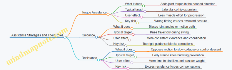
Exoskeletons can help walking in three common ways: they add torque, they guide motion, or they apply resistance. The difference matters because each approach changes what the user must do to stay comfortable and stable.
Torque Assistance
Torque assistance means the suit actively supplies rotational force at a joint, typically the hip or knee. The controller estimates where the joint is in the gait cycle and then applies a commanded torque profile.
A practical example is hip extension support during late stance. When the leg is behind the body, the user’s hip extensors may be weak or fatigued. The suit can add torque that helps rotate the thigh backward, which in turn supports forward progression without forcing the user to “push harder” with the body.
Best practice is to match the timing and direction of assistance to the user’s natural gait. If the suit helps too early, it can pull the leg into a posture the user is not ready to accept. If it helps too late, it may feel like the suit is “catching up” rather than supporting the step.
A simple way to think about it: torque assistance changes the user’s required muscle effort by adding a controllable share of joint work.
Guidance
Guidance means the suit shapes the motion path without directly trying to supply the full amount of joint torque the user would otherwise need. In practice, guidance is often implemented as a constraint or a soft “preference” for joint angles and trajectories.
Example: knee guidance during swing. If a user tends to keep the knee too bent or too straight, the suit can bias the knee toward a target angle range as the foot moves forward. The user still initiates the step, but the suit reduces the degrees of freedom that lead to inefficient or unsafe positions.
Guidance is especially useful when the user’s problem is coordination rather than pure strength. For instance, someone may have enough leg power but inconsistent swing clearance. Guidance can help keep the foot trajectory predictable.
Best practice is to keep guidance compliant. If the suit “locks” the joint path, small user corrections become difficult, and the user may compensate elsewhere. Soft guidance lets the user deviate slightly while still being nudged toward a safer pattern.
Resistance
Resistance means the suit applies opposing torque or force to slow or control a motion. Resistance is not only for “making things harder”; it can be used to improve control and reduce harmful motion.
Example: controlled knee flexion resistance during early stance. If a user’s knee buckles or collapses, the suit can apply resistance that limits how quickly the knee drops. The goal is to buy time for the user to stabilize the leg and transfer weight.
Resistance can also help with step lowering. During sit-to-stand transitions or controlled descent, resistance can prevent abrupt joint motion that would otherwise require the user to react instantly.
Best practice is to tune resistance so it does not fight the user’s intent. If resistance is too strong, the user may lean or step differently to avoid it. If it is too weak, it won’t correct the instability.
How They Differ in Everyday Terms
- Torque assistance reduces effort by adding joint work.
- Guidance reduces variability by shaping motion choices.
- Resistance reduces unwanted motion by opposing speed or collapse.
A helpful mental model is to ask: “What problem am I trying to fix?” If the answer is low strength, torque assistance often fits. If the answer is inconsistent joint positioning, guidance often fits. If the answer is unstable or unsafe motion, resistance often fits.
Mind Map: Assistance Strategies and Their Roles
Example: Choosing the Right Mode for One Step
Consider a user who reports “my knee feels like it gives out when I start walking.”
- If the knee gives out because the user cannot generate enough extension torque, torque assistance can support the joint when it matters.
- If the knee gives out because the user’s knee angle varies too much during stance, guidance can stabilize the knee’s trajectory.
- If the knee gives out because it drops too quickly, resistance can slow the collapse and improve stability.
In practice, suits often blend these approaches. The blend should be deliberate: each component should address a specific failure mode rather than all aiming at the same symptom.
Quick Comparison Table
| Mode | Primary Goal | Common Joint Use | What the User Feels | Main Tuning Lever |
|---|---|---|---|---|
| Torque Assistance | Reduce effort | Hip or knee | “The suit helps me push” | Timing and magnitude |
| Guidance | Improve coordination | Knee or ankle | “The suit keeps me on track” | Angle targets and compliance |
| Resistance | Control instability | Knee or hip | “The suit slows my collapse” | Strength and onset rate |
3.2 Sit-to-Stand, Stairs, and Uneven Terrain Use Cases
Exoskeleton walking suits can help most when the assistance matches what the body is already trying to do. Sit-to-stand, stairs, and uneven terrain each change the “job” of the legs: the first is a controlled rise, the second is repeated elevation changes, and the third is continuous balance correction. Good use cases therefore start with clear intent, predictable timing, and conservative safety boundaries.
Sit-To-Stand Use Case
Sit-to-stand is less about forward walking and more about transferring load from the seat to the feet. A practical best practice is to begin with a stable stance plan: feet planted, hips close to the chair edge, and a consistent hand position for balance. The suit should support hip extension and knee extension in a way that reduces the user’s need to “fight” the motion.
A simple example: a user sits with knees at about 90 degrees. On command, the suit first assists trunk posture and hip extension gradually, then increases knee extension as the feet load rises. If the user’s heels lift early, the controller can reduce knee torque and prompt a slower rise, because early heel lift often signals insufficient balance or insufficient foot contact.
Key checks:
- Chair height: too low forces deep knee flexion and increases required torque.
- Foot placement: if the feet are too far forward, the user may need extra hip torque to prevent sliding.
- Timing: assistance should ramp smoothly, not “snap” into full support.
Stairs Use Case
Stairs require a different rhythm than level walking because each step changes both vertical position and required joint moments. The suit must coordinate swing clearance with controlled stance loading. A best practice is to treat stairs as a sequence of discrete steps rather than continuous walking.
Example: ascending stairs with a handrail. The user places the leading foot on the next step. The suit assists hip and knee extension to lift the body, then supports controlled knee flexion during the transfer so the trailing foot can clear the step edge. If the trailing foot catches, the suit can increase swing clearance only during the swing window, rather than raising assistance during stance where it could destabilize balance.
Safety practices that matter:
- Use a handrail when available; the suit is assistance, not a substitute for balance support.
- Start with low step heights or a training rig to verify clearance.
- Keep step cadence slow enough that the suit can reliably detect phase transitions.
Uneven Terrain Use Case
Uneven terrain adds variability: the ground plane tilts, steps differ in height, and foot contact timing becomes less consistent. The suit’s job shifts toward maintaining stable posture and preventing unwanted joint motions when the foot lands unexpectedly.
Example: walking on a sloped path with a small curb. As the leading foot approaches the curb, the suit can prepare by increasing clearance and slightly adjusting stance support to reduce the chance of the foot striking the curb edge. After contact, assistance should prioritize stability—limiting excessive knee extension if the user’s center of mass shifts unexpectedly.
A practical approach is “contact-aware assistance.” Instead of assuming a fixed gait phase duration, the suit can use foot contact and force cues to decide when to transition. If contact is delayed, the controller delays stance assistance ramp-up, which helps avoid pushing against a foot that hasn’t fully loaded.
Mind Map: Use Case Requirements and Practices
Case Study: One Day, Three Scenarios
A user trains in a clinic with three short sessions. First, sit-to-stand: the chair is set to a height that keeps knee flexion moderate. The suit assists hip extension early and knee extension later, and the user practices a consistent “pause” at full standing to confirm stability.
Second, stairs: the user starts with a single step up and down while holding the handrail. The suit increases swing clearance for the trailing foot and limits stance assistance to prevent pushing the user forward too quickly.
Third, uneven terrain: the user walks a short path with a curb and a slight slope. The suit uses foot contact cues to delay stance ramp-up when loading is delayed, and it reduces assistance if the user’s posture indicates a balance correction is needed.
The result is not just smoother motion. Each scenario uses a different control emphasis—rise transfer, step clearance, or stability under contact uncertainty—so the suit behaves like a helpful partner rather than a one-size-fits-all walker.
3.3 Foot Clearance, Swing Control, and Foot Drop Support
Foot clearance is the difference between a step that lands cleanly and one that catches the toe. In walking suits, it is mostly a swing-phase problem: the foot must lift enough, move forward at the right time, and then lower with controlled contact.
Foot Clearance Targets and What “Enough” Means
A practical clearance goal is “toe height above the ground during mid-swing.” Designers often translate this into a measurable quantity using the user’s typical stride and floor height. A useful best practice is to set clearance targets as a function of gait speed and step length rather than a single fixed number.
Easy example: if a user’s toe height drops when they slow down, a constant clearance setting can over-lift them at slow speeds and still under-lift them at faster ones. Instead, the suit can increase assistance when step timing indicates a shorter swing or when the user’s foot trajectory shows reduced lift.
Swing Control: Timing First, Then Magnitude
Swing control is not just “how much torque.” It is also “when.” The suit needs a reliable estimate of swing start and swing end so it can apply assistance during the window where it matters.
Best practice: use a two-stage approach.
- Detect swing phase with conservative thresholds so the suit does not start lifting too early.
- Apply assistance with a smooth ramp so the foot trajectory changes gradually.
Easy example: if assistance begins at heel-off but the phase detector is late, the suit may try to correct too late, causing a sudden lift that feels like a bump. A ramped torque profile reduces that sensation and improves consistency.
Common Foot Drop Patterns and How Suits Address Them
Foot drop usually shows up as insufficient dorsiflexion during early swing, sometimes combined with weak control near heel strike. The suit’s job is to prevent toe drag while preserving a natural lowering at contact.
Three common patterns:
- Early swing toe drag: the toe stays low right after swing begins.
- Late swing scuffing: the toe lifts initially but drops again before the foot reaches forward position.
- Landing instability: the foot lands with poor control, leading to awkward loading or repeated adjustments.
Easy example: a user may have toe drag only when turning. Turning changes step timing and trunk motion, so the suit should not rely on straight-walking assumptions. The control logic can treat turns as a different timing regime by using step-to-step timing cues.
Control Strategies for Clearance and Dorsiflexion Support
A common approach is to combine dorsiflexion assistance with guidance on foot angle or shank motion. The suit can use impedance-like behavior so the user still contributes effort.
Best practice: “assist-as-needed” with limits.
- If toe clearance is adequate, the suit reduces assistance.
- If clearance falls below target, it increases assistance within safe bounds.
- If the user’s own motion is already correcting the drop, the suit should not fight it.
Easy example: during a recovery step after a stumble, the user may temporarily over-dorsiflex. Assist-as-needed can detect that clearance is already high and back off, preventing the foot from feeling forced upward.
Practical Tuning Workflow for Real Users
A reliable tuning workflow prevents the classic problem of “it works in the lab, not on the floor.”
- Start with swing timing: verify the suit starts assistance at the correct moment by watching foot trajectory relative to gait events.
- Tune lift magnitude: adjust until toe clearance is consistent across several steps.
- Tune lowering behavior: ensure the foot transitions smoothly toward contact without slamming.
- Check variability: test across small speed changes and short pauses.
Easy example: if the suit gives great clearance but the user’s heel strike becomes noisy, the lowering phase likely needs gentler control. Reducing stiffness near the end of swing often improves comfort without sacrificing clearance.
Mind Map: Clearance and Swing Control
Example: Turning with Foot Drop
Consider a user who shows toe drag mainly during turns. Straight walking tuning may set dorsiflexion assistance correctly for one timing pattern, but turning changes stride timing and trunk motion.
A practical fix is to base assistance on step timing cues rather than only on joint angles. The suit can increase dorsiflexion support when it detects shortened swing duration or altered swing onset timing. Then it can reduce assistance once clearance is achieved, so the user does not feel over-lifted during the turn.
Example: Preventing Late Swing Scuffing
Late scuffing often means the suit lifts early but then relaxes too soon. A straightforward remedy is to extend the assistance window slightly into late swing while keeping the lowering phase gentle.
Easy example: if toe clearance is high at mid-swing but drops near swing end, shift the control emphasis from a single mid-swing target to a trajectory-based target that checks clearance near the end of swing as well. This reduces the “toe up, toe down” pattern without increasing overall lift unnecessarily.
Example: Landing Control Without Toe Stubbing
If the user lands with a stiff or awkward foot, the suit may be too aggressive near contact. A better approach is to separate clearance support from landing behavior.
Easy example: keep dorsiflexion assistance active until just before contact, then switch to a softer behavior that allows the foot to settle naturally. The result is fewer abrupt contacts and a more stable transition into stance.
3.4 Endurance Support and Fatigue Management Strategies
Endurance support is about keeping walking assistance useful for longer sessions without turning the suit into a battery-powered crutch. Fatigue management is about reducing the user’s workload while also preventing the suit from “chasing” tired movement patterns in a way that feels unpredictable.
What Fatigue Looks Like During Assisted Walking
Fatigue usually shows up as slower step timing, smaller joint excursions, and changes in how the user distributes effort across hips, knees, and ankles. In practice, you may see foot clearance drop first, then posture control degrade, and finally the user starts relying more on upper-body support or shorter strides. A good endurance strategy treats these as signals, not as failures.
A simple example: after 20 minutes, a user begins to shorten stance time. If the suit keeps applying the same assistance schedule, the user can feel “pulled” into a gait they can’t sustain. The fix is to adapt assistance to the user’s current pacing and stability, not to the original calibration.
Designing Assistance That Stays Useful
Endurance support starts with limiting how much the suit asks the user to do. If the suit provides torque assistance only when the user is already producing good mechanics, it can inadvertently increase effort when fatigue changes the mechanics. Instead, assistance should be structured so the user gets help with the tasks that fatigue most strongly affects: initiating swing, maintaining safe foot clearance, and stabilizing stance.
A practical approach is to use assist-as-needed logic with clear thresholds. Example: if swing-phase timing drifts beyond a set range and foot clearance approaches a safety margin, the suit increases assistance for swing initiation and toe clearance. If the user is stable and clearing the foot comfortably, assistance returns to a lower level.
Managing Energy Without Losing Control
Energy management is not only about runtime; it’s also about keeping actuation behavior consistent. If the suit reduces power too aggressively as the battery drains, the user experiences a gradual change in assistance “feel,” which can increase effort and worsen fatigue.
Best practice: plan for derating that preserves control authority. Example: rather than dropping maximum torque abruptly at a low battery percentage, the system can reduce assistance magnitude gradually while keeping the same control gains and safety limits. The user then experiences a predictable reduction in help rather than a sudden shift.
Another best practice is to avoid wasting energy on corrections the user doesn’t need. Example: if sensors indicate the user is walking straight with good balance, the suit should not apply extra lateral stabilization effort. Stabilization should be proportional to measured instability, not to a fixed schedule.
Fatigue-Aware Control and Adaptation
Fatigue-aware control means the suit adapts to changes in gait quality while staying within safety boundaries. The adaptation should be slow enough that it doesn’t feel like the suit is “learning” mid-step.
A concrete example: monitor step-to-step variability in timing and joint angles. If variability increases over several steps, reduce assistance aggressiveness slightly and increase stability-focused support. This helps prevent the suit from overcompensating for inconsistent movement.
To keep adaptation safe, use guardrails:
- Cap how quickly assistance levels can change.
- Require multiple consecutive steps to confirm a fatigue trend.
- Prefer stability and clearance support over large torque changes.
Monitoring and Session Planning
Fatigue management includes operational choices. Shorter sessions with more frequent breaks often outperform one long session, especially when the user is learning to trust the assistance.
A simple session plan example:
- First 5 minutes: lower assistance to establish comfortable pacing.
- Middle 10–15 minutes: enable endurance mode that emphasizes clearance and stance stability.
- Final 5 minutes: reduce assistance slightly and focus on confidence tasks like controlled turns or steady walking.
During the session, watch for early fatigue cues: increased reliance on handrails, reduced step length, and longer time spent in stance. If these appear, pause and reassess fit and comfort before increasing assistance.
Mind Map: Endurance Support and Fatigue Management
Example: Adjusting Assistance as Fatigue Builds
Consider a user who starts with comfortable toe clearance and consistent timing. After 15 minutes, sensors show swing timing drifting and clearance nearing the safety margin. The endurance strategy increases swing-focused assistance modestly while keeping stance stability support steady. At the same time, assistance changes are limited to a small step-to-step increment, so the user feels a gradual improvement rather than a sudden shift.
If the user’s variability continues to rise for several steps, the system transitions from torque-heavy support to stability-focused support, and the session pauses for a short rest and fit check. This prevents the suit from compensating for fatigue indefinitely and keeps the assistance aligned with what the user can reliably execute.
4. Sensors, Estimation, and State Awareness
4.1 IMUs, Encoders, and Force Sensing Explained
Exoskeletons need to know what the user is doing right now, not what they did a second ago. That “right now” picture comes from three common sensing families: inertial measurement units (IMUs), joint encoders, and force sensing. Each one measures a different slice of reality, and each one has failure modes that the others can cover.
IMUs and What They Measure
An IMU typically combines a gyroscope, an accelerometer, and often a magnetometer. The gyroscope measures angular velocity, which is excellent for detecting turns and estimating how fast a segment is rotating. The accelerometer measures specific force, which includes gravity and any linear acceleration. During walking, linear acceleration changes from step to step, so accelerometer readings alone can be misleading for long-term orientation.
To make IMUs useful, systems estimate orientation by fusing signals. A common approach is to combine gyro integration (smooth short-term motion) with accelerometer gravity alignment (stable long-term reference). The result is an orientation estimate that can drive gait-phase detection and posture awareness.
Easy example: If the shank sensor shows the knee segment rotating forward quickly, the controller can anticipate swing. If the orientation estimate drifts over time, the controller can still rely on encoders for joint angle truth.
Encoders and Joint Angle Truth
Encoders measure position or rotation at a joint or drivetrain. Incremental encoders count pulses; absolute encoders provide a direct angle reading. Encoders are usually the most direct way to know where the exoskeleton’s joints are, because they sit on the mechanism that actually moves.
Encoders still have practical issues. Backlash, belt stretch, or cable compliance can create a gap between commanded motion and measured motion at the user’s limb. Also, if the suit is not aligned during fitting, the encoder’s “zero” may not correspond to the user’s anatomical neutral.
Easy example: During sit-to-stand, the controller can watch the hip encoder angle increase smoothly. If the IMU says the torso is stable but the hip angle is changing, the system knows the motion is coming from the legs, not a sensor glitch.
Force Sensing and Interaction Awareness
Force sensing answers a different question: not “where is the joint,” but “how hard is the suit pushing or being pushed back.” Common options include load cells, strain gauges, and force-sensitive resistors. Many systems measure forces at the footplate, at the knee/hip interfaces, or in line with an actuator.
Force signals help separate intentional assistance from accidental contact. They also improve comfort by preventing the controller from applying torque when the user is already supporting themselves.
Easy example: If the footplate force drops unexpectedly while the controller thinks the foot is still in stance, the system can reduce assistance to avoid pushing against an unloading foot.
Mind Map: Sensor Roles and Typical Signals
How Signals Work Together in Walking
A practical fusion strategy is to treat each sensor as a “vote” with different strengths. Encoders provide joint angles and timing of mechanical motion. IMUs provide segment orientation and motion rates, which help detect gait phase even when joint angles change slowly. Force sensing confirms contact events and interaction intensity.
When signals disagree, the controller should not blindly trust one source. For instance, if encoders indicate the knee is flexing but force sensing still shows high stance load, the system can interpret the motion as controlled weight transfer rather than a full swing transition.
Easy example: During a stumble recovery, the user may change stride timing. IMU motion rates can spike, encoders show rapid joint changes, and force sensing reveals whether the foot is still bearing weight. Together, these signals let the controller adjust assistance without assuming a normal gait pattern.
Practical Calibration and Signal Quality Checks
Before walking begins, sensors must be calibrated and sanity-checked. IMUs need a stable reference orientation so gravity alignment is correct. Encoders need a mapping from mechanical zero to the user’s anatomical reference, typically established during fitting. Force sensors require baseline offsets and consistent mounting so that “no load” truly means no meaningful interaction.
Signal quality checks are equally important. Controllers often monitor for saturation, sudden discontinuities, and implausible rates of change. If an IMU reports a sudden jump in orientation while encoders remain smooth, the system can down-weight the IMU for that interval.
Easy example: If the IMU cable connection loosens, the IMU may output erratic values. Encoders still track joint motion, and force sensing still indicates contact, so the controller can keep assistance conservative until the IMU signal stabilizes.
4.2 Gait Phase Detection and Step Timing Reliability
Gait phase detection is the job of answering one practical question: “Where are we in the walking cycle right now?” Step timing reliability is the job of making that answer stable enough that the suit’s assistance lands in the right place, on the right step, with the right strength.
What “Phase” Means in a Walking Suit
Most walking suits use a small set of phases rather than a continuous “percent of gait.” A common split is stance and swing, sometimes refined into early stance, mid stance, terminal stance, and early/mid swing. The suit does not need a perfect biomechanical label; it needs a consistent phase estimate that aligns with the user’s motion.
A useful mental model is to treat phase detection like a metronome that can tolerate tempo changes. If the metronome drifts, assistance arrives late or early, which can feel like the suit is “pushing at the wrong time,” even if the torque magnitude is correct.
Signals That Actually Help
Phase detection usually combines multiple sensors so that no single failure ruins the estimate.
- IMU orientation and angular velocity help identify trunk motion patterns and leg swing dynamics.
- Joint encoders help detect knee and hip angle trajectories that correlate with stance-to-swing transitions.
- Foot contact sensing (force/pressure or estimated contact from motion) is often the most direct cue for stance timing.
A practical best practice is to design the system so that phase can still be estimated when one sensor is noisy. For example, if foot pressure is unreliable due to shoe slip, the system can lean more on leg angle and trunk motion until contact becomes trustworthy again.
A Reliable Step Timing Pipeline
A robust pipeline typically has four stages.
- Preprocessing: filter sensor noise and normalize signals across users.
- Event detection: find candidate events like heel strike and toe-off.
- Phase inference: convert events into a phase estimate using a state machine or cycle model.
- Timing refinement: correct drift using recent steps and consistency checks.
Event Detection with Guardrails
Heel strike and toe-off are tempting targets, but they can be confused by small shuffles, turning, or uneven surfaces. Guardrails reduce false events.
- Minimum time constraints: heel strike cannot occur twice within an impossible interval.
- Signal consistency: require agreement between at least two cues, such as a contact cue plus a leg-angle cue.
- Hysteresis thresholds: use different thresholds for entering versus leaving contact to prevent rapid toggling.
Mind Map: Gait Phase Detection and Step Timing Reliability
Example: Detecting Stance-to-Swing Transition
Imagine a suit that assists hip extension during late stance and supports knee flexion during early swing. The system needs a reliable stance-to-swing transition.
A simple approach:
- Use foot contact pressure to mark stance when pressure exceeds a threshold.
- Detect toe-off when pressure drops below a lower threshold for a short confirmation window.
- Use knee angle velocity to confirm: early swing typically shows a change in knee motion direction.
Concrete reliability detail: if pressure briefly dips due to a momentary shift, the confirmation window prevents the system from declaring toe-off too early. If the user is walking slowly, the confirmation window can be slightly longer so that the system doesn’t “snap” into swing based on a brief signal artifact.
Example: Step Timing Under Speed Changes
Cadence changes are normal. The reliability challenge is avoiding phase jumps.
A practical method is to maintain an estimate of step period from recent steps and update it gradually. When a new step arrives, compute the time difference from the last detected event and compare it to the running estimate.
- If the new step period is within a reasonable range, update the estimate with a small correction.
- If it is far outside the range, treat the event as suspicious and rely more on other cues until the timing stabilizes.
This prevents the suit from “chasing” a single odd step, which is especially important when the user is turning or stepping around obstacles.
Measuring Timing Reliability in a Way That Matters
Timing reliability should be measured against what the suit does, not just against labels.
- Event timing error: difference between detected and reference heel strike/toe-off times.
- Step period variance: how much the estimated step interval fluctuates.
- Assistance alignment score: whether assistance onset falls within an acceptable window relative to the gait phase.
A good validation practice is to test multiple walking styles: steady straight walking, slow walking, short steps, and turning. The phase detector should remain stable even when the gait pattern changes, because the suit’s job is to adapt without becoming unpredictable.
Common Failure Modes and Fixes
- False heel strike from toe drag: require contact plus a leg-angle cue, and enforce a minimum stance duration.
- Missed toe-off during slow swing: adjust confirmation timing and allow phase inference to continue through a short contact ambiguity.
- Drift over several steps: use a state machine that can re-synchronize when a strong event is detected.
- Sensor dropout: switch to fallback weighting so the phase estimate remains usable until the primary cue returns.
When phase detection and step timing are reliable, the suit’s assistance feels like it belongs to the user’s motion. When they are not, the suit can still be powerful, but it will feel mistimed. Reliability is the difference between “helpful” and “confusing,” and it is earned one step at a time.
4.3 Estimating Center of Mass and Posture for Stability
Stability starts with knowing where the body’s mass is trying to go. In an exoskeleton, you rarely measure “center of mass” directly; instead, you estimate it from segment geometry, joint angles, and a few sensor signals. The goal is not perfect physics—it’s a consistent estimate that stays accurate enough to prevent the suit from assisting in the wrong direction.
What You Need to Estimate
A practical stability estimate usually includes:
- Center of Mass location in the sagittal plane (forward/back) and sometimes the frontal plane (left/right).
- Body orientation such as trunk pitch and roll, because posture errors can masquerade as COM errors.
- Support context like stance foot identification and whether the user is leaning or stepping.
A helpful mental model is: COM tells you “where weight is,” while posture tells you “how the body is shaped right now.” If posture is wrong, COM will be wrong even if your math is correct.
Segment-Based COM Estimation
Most systems approximate the body as linked segments (shank, thigh, pelvis/trunk, and sometimes arms). Each segment has:
- A length and mass fraction (from anthropometric tables or calibration).
- A pose derived from joint angles and sensor orientation.
Then the COM is the weighted average of segment COMs. In the sagittal plane, you can compute a 2D COM position using segment midpoints and their angles.
Easy example: Suppose the user’s trunk pitch increases by 10°. Even if the legs stay still, the trunk segment COM shifts forward. A suit that only looks at leg joint angles might think the user is stable, while the trunk shift actually moves the COM toward the edge of the support polygon.
Using Sensors Without Overtrusting Them
Inertial sensors (IMUs) provide orientation, but they drift over time. Encoders provide joint angles, but they can be biased if the suit is misaligned. A robust estimate blends both.
A common approach is:
- Use IMU orientation to anchor trunk posture.
- Use encoder angles to compute leg segment poses.
- Apply a correction step when the stance foot is detected, because stance moments constrain the body motion.
Easy example: If the user is standing still, the COM estimate should settle. If it keeps “walking” forward and backward, you likely have either encoder offset error or IMU bias.
Stability-Relevant Posture Features
Not every posture detail matters equally. For walking stability, these features are especially useful:
- Trunk pitch and angular velocity to detect forward lean and sudden recovery.
- Pelvis orientation relative to the suit frame to catch alignment issues.
- Knee and hip flexion angles to infer whether the user is using a “soft knee” strategy or locking joints.
Easy example: Two users can have the same estimated COM position, but one keeps knees slightly flexed while the other locks the knees. The locked-knee posture reduces the ability to absorb perturbations, so the suit should be more conservative with assistance.
Support Polygon and Margin of Stability
Once you have COM position, you compare it to where the body can “pivot” safely. In simple terms, you check whether the COM projection lies within a support region.
A practical method is to compute a stability margin:
- Determine the stance foot and its approximate contact area.
- Project the COM onto the ground plane.
- Measure distance from the projection to the edge of the support region.
Easy example: During early stance, the user’s COM projection may be near the front edge of the foot. If the suit applies hip extension torque that increases forward lean, the COM margin shrinks quickly. If instead the suit uses assistance that supports controlled progression, the margin stays healthier.
Mind Map: Center of Mass and Posture Estimation
Example Workflow for a Single Step
- Detect stance foot using foot contact timing and leg motion patterns.
- Compute segment poses from encoder angles and suit kinematics.
- Anchor trunk pose using IMU orientation, then compute trunk segment COM.
- Fuse estimates so COM doesn’t jump when sensors disagree.
- Project COM to ground and compute stability margin.
- Feed margin and posture features into the control logic so assistance is adjusted before instability grows.
Easy example: If the user begins to stumble forward, trunk pitch velocity increases first. The posture features react quickly, and the COM projection follows. The suit can reduce assistance that would otherwise push the user further forward, buying time for the user’s corrective motion.
Common Failure Modes and What to Check
- Suit misalignment: COM estimate shifts systematically even when the user’s posture is unchanged. A quick standing check reveals consistent offsets.
- IMU bias: Trunk angle slowly drifts, causing COM drift. Look for gradual COM movement during quiet standing.
- Wrong stance detection: Support polygon changes abruptly, making the stability margin jump. Smoothing stance transitions prevents sudden control changes.
- Anthropometric mismatch: Segment mass fractions don’t match the user, skewing COM. Calibration can reduce this, but the system should still behave safely if estimates are imperfect.
A good stability estimate is boring in the best way: it changes smoothly during normal walking, reacts appropriately during lean or recovery, and fails gracefully when sensors disagree.
4.4 Calibration Procedures for Consistent Assistance
Calibration is the part where a walking suit stops guessing and starts matching the user’s body. The goal is simple: when the controller thinks the user is at a certain joint angle or gait phase, the suit should apply assistance that feels repeatable across steps, days, and minor changes in clothing or posture.
Calibration Mind Map
Preparation That Prevents Most Problems
Start with a repeatable donning routine. If the suit is tightened differently each time, the mechanical zero changes, and the controller will “help” based on a shifted baseline. Use the same clothing thickness, liner placement, and strap order. Before any walking, check battery level, confirm sensors stream data without dropouts, and verify that actuators can move through a small safe range with the user standing supported.
A practical habit: record a short “stillness” segment for sensor bias. Even a few seconds of quiet standing helps estimate IMU offsets and reduces false motion detection.
Coordinate Alignment and Mechanical Zero
Alignment is where many calibration errors hide. The suit must know which way the user’s pelvis and limbs are oriented relative to the suit frame. During alignment, map each joint center to the suit’s joint axis. If the knee joint center is off by even a couple of centimeters, the same commanded actuator motion can create a different effective joint torque.
Mechanical zeroing should be done with the user in a known posture. Choose a stance where the user can hold steady: feet flat, knees comfortably extended, and pelvis level. Then set encoder zeros and confirm that the suit’s joint angles match a simple visual check. A good rule is to compare left and right joint angle readings while the user stands symmetrically; large differences suggest mapping or strap issues.
Sensor Calibration for Reliable State Estimation
IMU calibration typically includes bias estimation and orientation alignment. Bias is the sensor’s tendency to report a nonzero value while stationary. Orientation alignment ensures the suit interprets “forward” and “up” consistently.
Encoder zeroing is not just setting a number. Backlash and looseness can cause a delay between commanded motion and measured motion. After zeroing, gently move the joint through a small angle and confirm that the encoder tracks smoothly without sudden jumps.
If the suit uses force or torque sensing, calibrate offsets while the user is supported and the load is stable. For example, if a force sensor reads a nonzero value while unloaded, the controller may think the user is resisting when they are not.
Gait Phase Calibration with Short Trials
Phase calibration aligns the controller’s notion of “where you are in the step” with the user’s actual step timing. Use short walking trials on a flat surface. The suit should detect step events such as heel strike and toe off, then map them to actuator timing.
A simple procedure is threshold tuning using a few representative steps. Start with conservative thresholds that avoid triggering assistance during stance transitions. Then adjust so that assistance begins near the intended moment, not too early and not too late.
Timing matters. If assistance starts during the wrong part of stance, it can feel like the suit is pushing against the user’s intent. If it starts too late, the user may feel under-supported during the transition to swing.
Control Parameter Tuning for Consistent Feel
Once state estimation is stable, tune assist-as-needed thresholds. A practical approach is to set thresholds based on measured joint torque or user effort signals so that assistance scales with effort rather than with noise.
Impedance gains should be tuned for comfort and predictability. If the suit feels “stiff,” reduce stiffness or increase damping so the user can move naturally. If it feels “sloppy,” increase stiffness slightly or tighten rate limits so the assistance doesn’t lag behind.
Always set saturation limits and rate limits. These prevent sudden large torques if a sensor glitch occurs or if the user changes stride length.
Consistency Checks That Catch Donning Variation
Run a repeatability check: perform the same short walking sequence three times. Compare key outputs such as estimated joint angles, detected step timing, and commanded assistance magnitude. Consistency doesn’t mean identical numbers; it means the pattern is stable and the user reports the same “feel” across trials.
Then do a cross-day check. Even if you calibrated yesterday, repeat the stillness sensor bias and a quick alignment verification. If the user reports a change in comfort, investigate strap tension and joint mapping before touching control gains.
Common Failure Modes and How to Fix Them
- Misalignment from donning variation: Symptoms include different assistance feel left vs right or across days. Fix by standardizing strap order and redoing joint mapping and mechanical zero.
- Sensor drift or loose straps: Symptoms include assistance triggering at odd times. Fix by tightening straps to the same tension and recalibrating IMU bias.
- Wrong joint mapping: Symptoms include assistance that feels like it’s acting at the wrong moment or wrong direction. Fix by re-centering joint axes and verifying angle readings against a visual check.
Example Calibration Workflow
Scenario: A user reports that the suit feels supportive on the first few steps but becomes less helpful later.
- Repeat the donning routine and confirm strap tension is unchanged.
- Re-run stillness bias calibration for IMU.
- Verify encoder zero and check for backlash by moving each joint through a small angle.
- Re-tune gait phase thresholds using 5–10 short steps, ensuring assistance onset matches the intended stance-to-swing transition.
- Perform three repeatability trials and compare commanded assistance magnitude during the same phase window.
If the commanded assistance magnitude drops later, the issue is often phase detection drifting due to sensor noise or threshold settings. If the magnitude stays constant but the feel changes, the issue is more likely mechanical alignment or strap tension changing during walking.
5. Control Architectures for Safe, Natural Walking
5.1 Finite-State Control and Gait-Phase Switching
Finite-state control treats walking as a sequence of distinct modes, each with its own control objective and safety rules. Instead of trying to command “the perfect motion” at every instant, the controller decides which phase it believes the user is in, then applies a phase-appropriate assistance profile. The result is easier to reason about, easier to debug, and typically more stable when sensors are noisy.
Core Idea: Modes with Clear Responsibilities
A practical walking suit usually defines states such as:
- Stance: the foot is on the ground; assistance supports load transfer and knee/hip stability.
- Swing: the foot is off the ground; assistance supports forward progression and foot clearance.
- Sit-to-Stand: the user transitions from sitting to upright; assistance supports hip extension and trunk posture.
- Stop or Standby: assistance is reduced or held to prevent unintended torques.
Each state has three responsibilities:
- What to command (torque, impedance targets, or guidance constraints).
- What to trust (which sensors are reliable in that phase).
- What to watch (phase-specific safety checks).
State Transitions: Guard Conditions and Hysteresis
Transitions should not be triggered by a single threshold crossing. Use guard conditions that combine multiple signals and include hysteresis so the controller doesn’t “chatter” between states.
Common transition signals include:
- Foot contact estimate from force sensing or a foot-mounted model using IMU and timing.
- Knee angle trend to detect stance loading versus swing extension.
- Hip angular velocity to detect the start of swing.
A typical stance-to-swing transition might require:
- Contact probability drops below a threshold for a short window (e.g., 50–150 ms).
- Hip angular velocity indicates forward swing initiation.
- Knee angle is not collapsing (to avoid switching during a stumble).
A typical swing-to-stance transition might require:
- Contact probability rises above a threshold.
- The foot is not moving backward rapidly (reduces false positives when the foot scrapes).
- Timing constraints: the step duration must be within a plausible range for the user.
Control Output per State
In stance, the suit often behaves like a stabilizing partner. For example, it can use impedance control targets that allow the user to feel support without locking joints. In swing, it can switch to a guidance profile that encourages safe foot trajectory while limiting excessive torques.
A simple way to implement this is to define per-state control parameters:
- Stance: higher damping at the knee, moderate hip assistance, and strict limits on hip flexion.
- Swing: assistance that increases with knee flexion and hip progression, plus a cap on peak torque.
- Stop: zero or near-zero commanded torque with a smooth ramp-down.
Mind Map: Finite-State Control and Gait-Phase Switching
Example: Stance-to-Swing Switching During Normal Walking
Assume the suit estimates foot contact using a force sensor on the insole plus a fallback model from foot IMU. The controller is in Stance.
- The user initiates a step. Knee begins to extend and hip begins to move forward.
- Contact probability drops from 0.9 to 0.4 as the heel lifts.
- The transition logic requires contact probability to stay below 0.5 for 80 ms.
- During those 80 ms, hip angular velocity exceeds a minimum value, confirming swing initiation.
- The controller switches to Swing and immediately changes the control objective: knee damping is reduced slightly to allow natural leg motion, while swing assistance ramps in with a torque rate limit.
If contact probability briefly dips due to a sensor glitch, the 80 ms confirmation window prevents an immediate state change.
Example: Swing-to-Stance Switching on Uneven Ground
Uneven ground can cause early contact or foot scuffing. Suppose the user is in Swing and the foot makes a light brush against the ground.
- Contact probability rises quickly, but knee angle is still flexed and hip angular velocity indicates the foot is not yet in a stable landing posture.
- The transition requires both: contact probability above 0.7 and knee angle within a landing range for 60 ms.
- The controller stays in Swing for the brush event.
- When the user truly lands, the knee angle and contact estimate align, and the controller switches to Stance.
This avoids the common failure mode where the suit “believes” the user landed too early and then applies stance stabilization at the wrong moment.
Example: Stop State Triggered by Unexpected Motion
If the user trips, the suit may detect a pattern such as sudden contact loss during stance combined with rapid knee flexion. In that case:
- A safety check flags “unexpected stance collapse.”
- The controller transitions to Stop rather than trying to guess the correct phase.
- Torque commands ramp down over a short interval to avoid abrupt changes.
- Once the user returns to a stable posture and contact estimate stabilizes, the controller can re-enter Stance or Standby based on the current conditions.
Minimal Pseudocode for Phase Switching
state = STANCE
loop:
  read sensors
  contact = estimate_contact()
  features = extract_joint_trends()

  if safety_fault_detected(features, sensors):
    state = STOP
  else if state == STANCE:
    if contact < T_stance_to_swing for confirm_ms
       and hip_vel > V_min
       and knee_not_collapsing:
         state = SWING
  else if state == SWING:
    if contact > T_swing_to_stance for confirm_ms
       and knee_in_landing_range
       and step_time_in_bounds:
         state = STANCE
  else if state == STOP:
    if posture_stable and contact_stable:
      state = STANCE

  apply_state_controller(state, features)
Finite-state gait control works best when the states are few, the transition conditions are conservative, and the controller is willing to stop rather than guess during uncertainty. That combination keeps assistance aligned with what the user is actually doing, not just what the sensors suggest at a single instant.
5.2 Impedance and Admittance Control for Comfort
Comfort is not just “soft control.” It is the way the suit reacts to small, normal human motions—like a slight stumble, a weight shift, or a pause at the end of a step—without making the user feel yanked, pinned, or overly constrained. Impedance and admittance control are two closely related ways to shape that interaction.
Impedance Control as “Force Personality”
Impedance control specifies how the suit should behave in terms of force response relative to motion. A common mental model is a spring-damper at each assisted joint: if the user’s leg moves a bit more than expected, the suit generates a restoring force that feels predictable rather than abrupt.
A typical impedance law uses three pieces:
- Stiffness: how strongly the suit resists deviation from a target joint angle or trajectory.
- Damping: how strongly it resists rapid changes.
- Feedforward or baseline torque: the torque needed for the nominal gait pattern.
Easy example: Suppose the suit targets a knee flexion angle during swing. If the user’s knee flexes slightly more than the target, stiffness produces a torque that nudges the knee back. If the user’s knee flexes quickly (maybe from a mis-timed step), damping reduces the “snap” by opposing the velocity.
Comfort best practice: Keep stiffness low enough that the user can correct their own gait without fighting the suit, but high enough to prevent wobble. Damping should be strong enough to smooth transitions, especially during phase changes.
Admittance Control as “Motion Personality”
Admittance control flips the relationship: it specifies how the suit should convert measured forces into motion commands. Instead of “force causes motion,” it behaves like a mass-spring-damper that turns interaction forces into a compliant trajectory.
A practical admittance loop often looks like this:
- Measure interaction force (or torque) at a joint or via estimated contact forces.
- Use an admittance model to compute a desired joint motion adjustment.
- Track that motion with a lower-level controller.
Easy example: During stance, the user leans slightly more onto one leg. If the suit senses higher hip or knee load, admittance can allow a small extra joint motion that reduces the feeling of being “held back.” The user still follows the gait plan, but the suit yields in a controlled way.
Comfort best practice: Ensure the admittance response is neither too sluggish (which feels like lag) nor too eager (which feels like the suit is chasing the user). The “mass” term in the admittance model strongly affects how quickly the suit reacts.
Choosing Between Impedance and Admittance
Both approaches can yield comfort, but they differ in what you tune.
- Impedance tuning is intuitive when you want to limit motion deviations and shape force felt by the user.
- Admittance tuning is intuitive when you want to let the user’s applied forces directly influence the suit’s motion.
In many real systems, designers use a hybrid structure: an admittance layer to handle interaction variability, plus an impedance-like behavior at the joint level to keep motion bounded.
Mind Map: Comfort Through Interaction Shaping
Concrete Tuning Workflow for Comfort
- Start with low stiffness or low admittance aggressiveness. The user should feel the suit “present” but not restrictive.
- Increase damping before stiffness. Damping reduces oscillations and makes the suit feel settled when the user changes their mind mid-step.
- Add bounds and rate limits. Even a well-tuned controller can behave badly if sensor noise spikes or if the user takes an unexpected step.
- Tune per joint and per phase. Swing and stance have different comfort needs; stance often benefits from compliance to load shifts, while swing benefits from smooth trajectory adherence.
Easy example: If ankle assistance feels twitchy during toe-off, first raise damping in the ankle impedance (or reduce admittance responsiveness). If the twitch persists, check for phase misclassification that causes the controller to switch targets at the wrong moment.
Example: Comfort During a Mis-Timed Step
Imagine the user starts swing a fraction late. Without compliance, the suit may apply assistance based on the planned phase, causing a noticeable mismatch. With impedance control, the suit’s stiffness and damping determine how much it resists the deviation while still allowing the user to catch up. With admittance control, the suit can interpret the interaction forces as “something is off” and adjust motion commands to reduce the mismatch.
A comfortable outcome looks like this: the user feels support, not correction. The suit helps stabilize the gait, but it does not force the user back into a rigid timeline.
Example: Comfort Limits That Prevent “Over-Help”
Comfort also depends on knowing when not to assist. If the user is already generating sufficient torque, additional assistance can feel like pushing. A simple practice is to cap the effective assistance based on measured interaction effort and to smoothly reduce gains when the user’s effort indicates they are in control.
Easy example: During sit-to-stand transitions, if the user’s measured hip torque is already high, the controller can lower the commanded assistance so the user does not feel like the suit is competing with their own effort.
Summary of Comfort Mechanisms
Impedance control shapes how forces arise from motion errors, while admittance control shapes how motion arises from interaction forces. Comfort comes from selecting gains that are responsive enough to support walking, but compliant enough to respect the user’s natural corrections—plus constraints that keep the interaction stable when the real world refuses to match the plan.
5.3 Assist-As-Needed Logic and Threshold Design
Assist-as-needed means the suit helps when the user needs it, and backs off when the user is already doing the job. The key is not just choosing a “help” signal, but designing thresholds that map measurable conditions to assist levels in a way that feels predictable.
Assist Level as a Function of Measured Need
Start by defining “need” using signals you can trust during walking. Common choices include joint torque tracking error, step timing irregularity, foot clearance margin, and trunk sway relative to a stability target. Each signal should have a clear direction: for example, larger tracking error implies more need, while smaller clearance margin implies more need.
A practical pattern is a three-band assist policy:
- Low need: assist is minimal or zero.
- Medium need: assist ramps up smoothly.
- High need: assist reaches a capped level and may switch to a more protective mode (like stronger swing support).
To avoid sudden changes, use hysteresis. Hysteresis means the threshold for turning assist on is slightly higher than the threshold for turning it off. This prevents “chatter” when the user hovers around a boundary.
Thresholds That Match Human Variability
Walking varies naturally across steps, so thresholds should be robust to short-term noise. Use a short window (for example, the last 3–5 gait events) and compute a stable statistic such as a median or a moving average. Then compare that statistic to thresholds.
Also separate thresholds by context. A clearance threshold that works on level ground may be too strict on a ramp, and a stability threshold may need different limits when the user is turning. If you do not want full context classification, you can still use conservative defaults and widen thresholds when uncertainty is high.
A useful rule: thresholds should be expressed in meaningful units. If your clearance margin is in centimeters, keep thresholds in centimeters. If your tracking error is in degrees or Newton-meters, keep it in those units. This makes tuning less guessy.
Example: Hip Extension Assistance with Hysteresis
Suppose the suit assists hip extension during late stance to reduce a tendency to under-extend. You measure hip extension tracking error during late stance.
- On threshold: tracking error median exceeds 6° for 3 consecutive late-stance windows.
- Off threshold: tracking error median drops below 4° for 3 consecutive windows.
- Ramp: between 4° and 6°, assist scales linearly from 0% to 50% of the maximum torque.
- Cap: above 6°, assist holds at 50% unless a separate high-need condition triggers a protective mode.
This design yields three benefits: it avoids rapid toggling, it tolerates step-to-step variation, and it keeps assist proportional rather than binary.
Example: Foot Clearance Support Using Margin Bands
For foot drop risk, define a clearance margin: the difference between measured toe height and a minimum safe height. Then use bands:
- Margin ≥ 4 cm: 0% assist.
- Margin 2–4 cm: ramp from 20% to 60% swing dorsiflexion assistance.
- Margin < 2 cm: 80% assistance plus a stricter timing constraint to avoid late dorsiflexion.
Add a timing gate so the suit only evaluates clearance during the swing window. Otherwise, the system might react to stance-phase toe trajectories that are irrelevant to clearance.
Mind Map: Assist-As-Needed Design
Threshold Tuning Workflow That Stays Grounded
- Start with conservative caps so that even “high need” assistance is not aggressive.
- Tune hysteresis first, because chatter is the most noticeable failure mode to users.
- Tune ramp slopes next, aiming for gradual change across steps rather than within a single step.
- Validate phase gating, ensuring the suit does not react outside the intended gait window.
- Check cross-signal interactions. If two signals both request high assist, decide whether you sum, prioritize, or take the maximum. A simple and predictable choice is “take the maximum requested assist level,” then apply a global cap.
Case Example: Two Signals Disagree
Imagine tracking error suggests high need, but clearance margin looks safe. If you simply take the maximum, the suit will assist based on tracking error, which might be correct if the user’s hip timing is off but the foot still clears.
If instead you average the two requests, you may under-assist hip extension and worsen timing, even though clearance is already adequate. A practical approach is to prioritize by function: clearance margin should dominate swing support, while tracking error should dominate joint torque assistance. When both relate to the same joint action, you can use maximum-plus-cap; when they relate to different actions, route each signal to its corresponding actuator.
Practical Threshold Checklist
- Thresholds have units and meaning.
- Each threshold uses a robust window.
- Every on/off boundary has hysteresis.
- Assist changes are phase-gated.
- Multiple requests follow a clear combination rule.
- Uncertainty leads to lower assist, not higher.
When these pieces are in place, assist-as-needed becomes less like a switch and more like a steady conversation: the suit helps when measurable performance drops, and it stops when the user is already stable and effective.
5.4 Safety Interlocks, Fault Handling, and Fail-Safe Behavior
Safety for walking suits is less about one magic safeguard and more about many small “nope” conditions that trigger at the right time. Interlocks prevent unsafe motion commands, fault handling keeps the system predictable, and fail-safe behavior defines what the suit does when things go wrong.
Safety Interlocks That Stop the Wrong Motion
Interlocks are rules that block assistance when the situation is outside allowed bounds. They should be checked continuously, not only at startup.
Common interlock categories
- State validity interlocks: If gait phase detection is uncertain, the suit reduces to guidance or disables torque assistance.
- Pose and balance interlocks: If the user’s trunk angle or lateral stability exceeds limits, assistance is withheld to avoid pushing a losing balance.
- Joint limit interlocks: If hip or knee angles approach mechanical or comfort limits, commands are clamped or reversed to a neutral posture.
- Speed and step timing interlocks: If step timing is inconsistent with the user’s recent pattern, the suit avoids aggressive timing-based torque.
- Power and thermal interlocks: If battery voltage sags or motors overheat, the suit reduces output rather than continuing at full effort.
Easy example A user starts walking and the suit expects a normal stance-to-swing transition. If the sensors report a sudden loss of contact or a phase estimate that jumps around, the interlock blocks torque assistance for the next step. The suit may still provide light guidance so the user can regain a stable pattern.
Fault Handling That Keeps Behavior Predictable
Fault handling defines what happens after an error is detected. The key design goal is consistency: the user should experience the same response every time the same fault occurs.
A practical fault-handling ladder
- Detect: Identify the fault source (sensor dropout, motor current spike, communication loss).
- Confirm: Require persistence for a short window to avoid reacting to brief noise.
- Classify: Decide severity: minor (reduce assistance), major (stop assistance), critical (stop and lock safe posture).
- Recover or hold: Either attempt a controlled recovery or hold the safe state until the user resets.
Easy example If an IMU briefly saturates during a quick turn, the system detects abnormal readings but confirms only after, say, 200 ms. If normal values return, it resumes assistance smoothly. If the fault persists, it transitions to a reduced mode and asks for a reset.
Fail-Safe Behavior That Defines the “Safe End State”
Fail-safe behavior is the suit’s default action when it cannot guarantee safe assistance. It should be simple enough to understand without reading logs.
Typical safe end states
- Torque to neutral: Motors stop applying assist torque and allow passive movement.
- Impedance relaxation: The suit reduces stiffness so it does not resist the user’s motion unexpectedly.
- Mechanical support mode: If available, the suit maintains a stable posture using low-risk constraints.
- User-dependent stop: The suit stops assistance but does not force a posture change.
Easy example During a sensor communication failure, the suit does not “guess” gait phase. It immediately transitions to torque neutral and keeps joint motion free. The user can then step carefully while the system requests a reset.
Interlock and Fault Logic Mind Map
Example Fault Scenarios with Expected Outcomes
Scenario A: Encoder dropout on one joint
- Detection: Joint angle readings become invalid.
- Interlock: Assistance for that joint is disabled.
- Fault handling: The suit switches to a mode that avoids timing-based torque.
- Fail-safe: Torque neutral for the affected joint; other joints may remain in reduced assistance if their sensors are healthy.
Scenario B: Motor current spike during stance
- Detection: Current exceeds a threshold for a confirmation window.
- Interlock: Torque commands are clamped.
- Fault handling: If the spike repeats, assistance stops for the next step.
- Fail-safe: Torque neutral to prevent continued loading.
Scenario C: Loss of controller communication
- Detection: Heartbeat missed.
- Interlock: No new assistance commands are accepted.
- Fault handling: Immediate transition to safe end state.
- Fail-safe: Torque neutral and impedance relaxation so the user is not surprised by resistance.
Implementation Practices That Make Safety Real
- Use monotonic safety states: Once the system escalates from reduced assistance to stop, it should not oscillate back and forth within seconds.
- Separate safety checks from performance control: Safety logic should run independently so a control bug does not disable safety.
- Log the reason, not just the event: Recording which interlock triggered helps clinicians and engineers correct the root cause.
- Test with “boring” faults: Sensor dropout, stuck values, and comms loss are common enough to deserve routine bench and treadmill tests.
A good safety design makes the suit’s response easy to predict: when a fault happens, the user gets a consistent, low-surprise behavior that prioritizes freedom of movement and stability.
6. Hardware Integration and Wearability Engineering
6.1 Frame Design, Fit Adjustment, and Load Distribution
A walking suit is only as helpful as its mechanical interface with the body. The frame’s job is simple: transfer forces to the skeleton and away from sensitive soft tissue, while keeping the user’s joints aligned with the suit’s joints. If the frame is even slightly misaligned, the control system can “do the right thing” and still produce uncomfortable or inefficient motion.
Frame Design Principles
Start with the load path. Assistance torque at the hip or knee must travel through the frame into body regions that can tolerate pressure and shear. Designers typically aim for contact zones over bony landmarks and use straps or cuffs to stabilize the frame without letting it drift.
Use stiffness where it matters, compliance where it helps. A frame needs torsional stiffness so it doesn’t twist under load, but it also benefits from controlled flexibility in areas that would otherwise concentrate pressure. For example, a rigid thigh shell can reduce wobble, while a slightly compliant liner can smooth out micro-movements.
Plan for adjustability from day one. A suit that fits perfectly on one person can be wrong for the next because limb lengths, pelvis width, and soft-tissue thickness vary. Adjustable ranges should exist for:
- Thigh and shank cuff positions
- Hip and knee joint center locations
- Strap tension and strap routing
- Footplate alignment relative to the ankle
Prevent frame migration. During walking, the suit experiences relative motion from skin sliding, muscle movement, and gravity. Anti-migration features can include wider cuffs, textured liners, and strap patterns that resist upward and rotational drift.
Fit Adjustment Workflow
A good fit is not a single measurement; it’s a sequence that checks alignment, comfort, and stability under motion.
- Baseline sizing. Set the frame so the major segments roughly match limb lengths. If the thigh and shank segments are too long, the suit will “fight” the user’s range of motion.
- Joint center alignment. Align the suit’s hip and knee joint centers with the user’s anatomical joint centers. A practical method is to move the user through a slow knee bend while observing whether the suit rotates smoothly without binding.
- Cuff placement and strap routing. Place cuffs so they contact stable regions. Tighten straps to remove slack, not to compress. A useful check is to look for skin bunching at the edges of cuffs.
- Footplate and ankle relationship. Ensure the footplate supports the foot without forcing plantarflexion or dorsiflexion. When the user stands, the foot should feel supported, not trapped.
- Static load test. With the user standing, apply a gentle assisted motion (or simulate it with manual actuation if available) and confirm that pressure points stay consistent.
- Dynamic verification. Walk a short distance and watch for frame drift. If the knee cuff creeps upward during steps, strap routing or cuff geometry needs adjustment.
Load Distribution: What to Aim For
Load distribution is about where forces go when the suit helps. The goal is to reduce peak pressure on soft tissue and avoid shear at the skin-frame interface.
Use multiple contact points. Spreading load across a larger area lowers peak pressure. For instance, a thigh cuff that contacts only a narrow band will feel “hot” quickly, while a wider cuff with a stable liner can stay comfortable for longer.
Control shear, not just pressure. Pressure alone can be tolerable; shear is often what causes discomfort during walking. Strap patterns that resist relative sliding help. A simple example: if the shank cuff shifts forward when the user steps, the liner may be allowing shear even if the cuff feels snug.
Match stiffness to the body region. Over a bony area, a stiffer interface can be comfortable because it reduces micro-motion. Over softer regions, too much stiffness can increase pressure peaks.
Mind Map: Frame Fit and Load Distribution
Example: Diagnosing a Knee Cuff That Feels Fine Standing but Not Walking
A user reports that the knee cuff is comfortable during a static stance test but becomes irritating after a few steps. During dynamic verification, the cuff is observed to creep slightly upward with each step. That pattern suggests shear and migration rather than insufficient pressure.
Fix approach:
- Re-route straps to increase resistance to upward drift.
- Check cuff width and liner grip; a smoother liner can increase shear.
- Reconfirm joint center alignment so the cuff is not being “pulled” by joint rotation.
- Re-run a short walk test and confirm that pressure points remain in the same region.
The key is to treat comfort as a mechanical outcome. If the frame migrates, the load distribution changes, and the user’s skin pays the price.
6.2 Interfaces for Skin, Liners, and Pressure Management
A walking suit is only as good as the interface between hardware and body. The interface has three jobs: transmit forces without slipping, protect skin from pressure and shear, and keep fit consistent as the user moves. If any job fails, the control system can be perfect and the experience still becomes uncomfortable or unsafe.
What “Interface” Really Means
Interfaces include liners, straps, cuffs, and any contact surface that touches skin. The key distinction is between normal pressure (force perpendicular to skin) and shear (force parallel to skin). Pressure can cause localized irritation; shear can cause friction blisters even when pressure seems moderate. A well-designed interface reduces both, while still allowing the suit to move with the user rather than against them.
Easy example: If a thigh cuff is tight enough to prevent slipping but the liner surface is slick, the cuff may slide a few millimeters each step. Those tiny shifts add up to shear, and the user feels “hot spots” after a short session.
Liner Materials and Contact Behavior
Liners usually aim for three properties: conformability, friction control, and moisture handling. Conformability helps the liner distribute load across a wider area. Friction control prevents unwanted sliding while allowing controlled micro-motion. Moisture handling matters because sweat changes skin friction and can increase irritation.
Easy example: A liner that feels comfortable when dry can become slippery after sweat. The suit then shifts, increasing shear at edges and concentrating pressure near strap boundaries.
Practical best practices:
- Use liners that match the user’s skin sensitivity and typical sweat level.
- Ensure the liner thickness supports consistent alignment; a “soft” liner that compresses too much can change joint mapping.
- Keep seams and hard edges away from bony prominences like the tibial crest.
Pressure Distribution and Fit Geometry
Pressure concentrates where the suit contacts the body most rigidly: edges of cuffs, strap anchor points, and any area where the frame bridges over soft tissue. Fit geometry should avoid “point loading” on small areas.
Best practices:
- Prefer wider contact regions over narrow bands when possible.
- Position contact areas so they align with muscle groups rather than bony landmarks.
- Re-check fit after the user stands and after the first few minutes of walking, because tissue compresses and settles.
Easy example: A knee cuff placed slightly too high may look fine seated, but during walking it can migrate and press on the kneecap area. The user reports discomfort specifically during stance, not while sitting.
Managing Shear with Anti-Slip and Allowable Motion
Shear management is about controlling relative motion. The interface should allow the suit to follow the limb’s movement while preventing sliding that drags skin.
Common strategies:
- Use friction surfaces that maintain grip under sweat.
- Add anti-slip patterns or compliant zones that reduce edge sliding.
- Design strap tension so it holds position without over-compressing.
Easy example: If a strap is tightened until it stops movement completely, it may increase pressure enough to cause redness within minutes. A better approach is to tune tension so the liner stays in place while the user can still tolerate the contact load.
Pressure Monitoring and Skin Checks
Pressure management is not only engineering; it is routine. Skin checks should be systematic and time-based.
Best practices:
- Perform a baseline check before donning the suit.
- After the session, inspect contact zones for redness that does not fade quickly, blistering, or persistent tenderness.
- Use a consistent schedule for reassessment, especially during early training.
Easy example: Two users can tolerate the same cuff tension, but one has fragile skin. The second user may show mild redness after 10 minutes while the first shows none after 30. The interface must be adjusted to the user, not the spec sheet.
Donning, Doffing, and Maintenance Routines
How the suit is put on affects pressure distribution. Donning should avoid wrinkles in liners and uneven strap placement.
Best practices:
- Don the liner smoothly, then attach straps in a consistent order.
- Confirm that contact areas sit flat without folds.
- Clean liners according to their material needs to preserve friction and moisture behavior.
Easy example: If a liner fold forms behind the knee, it can create a narrow pressure ridge. The user may not notice until the first stance phase, when the ridge compresses.
Mind Map: Skin Liners and Pressure Management
Example: Tuning a Thigh Cuff for Comfort and Stability
A user reports hot spots on the inner thigh after 15 minutes. The cuff does not visibly slip, but the liner shows slight migration at the strap edge.
Step-by-step adjustments:
- Reduce strap tension slightly to lower normal pressure.
- Check liner flatness and remove any fold near the inner thigh.
- Increase friction at the contact region by using the correct liner thickness and ensuring it is dry enough for the intended grip.
- Re-test after standing and after the first few minutes of walking.
Result: the cuff remains stable, but the hot spot shifts from a sharp point to a broader mild area that fades faster after the session.
Example: Preventing Knee Contact Irritation
A user feels discomfort during stance only. The knee cuff sits correctly while seated, but during walking it migrates upward.
Fixes:
- Reposition the cuff lower so it stays on the intended contact region during gait.
- Verify that the liner seam is not aligned with the cuff edge.
- Confirm strap tension is sufficient to prevent migration without excessive compression.
The interface becomes predictable across the gait cycle, which makes the rest of the system easier to tune.
6.3 Powertrain Layout and Cable Routing for Mobility
A walking suit’s powertrain is only as usable as its wiring. If cables tug, snag, or twist at the wrong moment, the user feels it as discomfort, the controller feels it as sensor noise, and the mechanics feel it as extra load. Good layout starts with deciding where motion happens and where it must not.
Powertrain Layout Principles
Start with the motion envelope. Map the hip, knee, and ankle ranges, then draw a “no-cable” volume around the joints. Cables should run through stable regions of the frame or along paths that move with the same rigid segment.
Keep the heaviest components close to the user’s centerline. A battery pack or motor controller mounted far to the side increases the moment arm during stepping. That shows up as higher torque demand and more noticeable sway.
Separate power and signal physically. Route motor power conductors away from sensor leads. Even with shielding, close proximity invites coupling, especially when current changes quickly during gait.
Plan for service access. If a connector is buried under a strap or liner, maintenance becomes a wrestling match. Place serviceable connectors where you can reach them without removing the entire suit.
Cable Routing Strategy
Use “path of least relative motion.” A cable should follow a route where the endpoints move together. For example, if a knee actuator is on the thigh frame, route its cable along the thigh frame and only transition to the shank at a fixed pivot-safe location.
Add strain relief at every transition. The cable should not carry mechanical load at the connector. Strain relief can be as simple as a clamp that takes tension before the connector sees it.
Control slack with predictable loops. Slack is not the enemy; uncontrolled slack is. A small, repeatable loop near the hip can accommodate flexion without letting the cable whip during heel strike.
Avoid sharp bends and pinch points. Use bend radii that match the cable spec and keep cables clear of frame edges. Pinch points often occur where straps cross the frame; add low-friction guides or protective sleeves.
Route along the frame, not through it. Internal channels reduce snag risk, but they must be sized for cable movement under vibration. If the cable rubs inside a tight channel, it will wear faster than expected.
Connector and Harness Design
Choose connector locations that match user comfort. Place connectors where they won’t press against the liner during standing. A connector that is “fine” in a bench test can become a pressure hotspot during walking.
Label by function, not by wire color. Colors fade, and field repairs happen. Mark harness ends by actuator or sensor channel so a technician can reconnect correctly without guessing.
Use consistent harness lengths. If one leg harness is longer than the other, the suit may bias the user’s posture. Match lengths so both sides experience similar cable tension throughout gait.
Example Layout for a Two-Leg Suit
Imagine a suit with hip and knee actuators on each leg, plus a battery and controller on the torso.
- Battery and main controller mount on the back plate near the centerline.
- Motor power cables run down the sides of the pelvis frame to each hip actuator.
- From the hip actuator, cables travel along the thigh frame to the knee actuator, staying inside the “no-cable” joint volume.
- At the knee, the cable transitions to the shank using a short, flexible segment with strain relief.
- Sensor leads (IMU, encoders, foot switch) route in a separate harness layer, clipped to the frame away from motor power.
This arrangement keeps the cable movement mostly aligned with the rigid segments, so the cable experiences bending rather than twisting.
Mind Map: Powertrain Layout and Cable Routing
Example: Diagnosing a Cable-Related Gait Issue
If a user reports intermittent discomfort near the knee during fast steps, check for cable tension changes at heel strike. A common cause is a cable loop that collapses under extension and then tightens abruptly. Fix it by relocating the loop slightly toward the thigh, adding strain relief closer to the knee actuator, and ensuring the cable lies along the frame rather than crossing the liner.
Example: Simple Routing Checklist
- Can you move each joint through its range without cable tension at the connector?
- Do any cables cross a joint axis inside the no-cable volume?
- Are motor power and sensor harnesses separated by a visible gap?
- Are there any sharp bends, especially near strap crossings?
- Do both legs have matched harness lengths and slack behavior?
A good harness disappears during use: it neither fights the user’s motion nor becomes an accidental sensor. When the cable path is planned around relative motion, the suit feels consistent step after step.
6.4 Weight, Center of Gravity, and How They Affect Gait
Weight is not just “how heavy the suit is.” It changes how hard the user’s body must work to start, stop, and redirect motion. Center of gravity (CoG) is the reason: it determines where the body’s balance forces need to act during each step.
Why Weight Changes Step Mechanics
A walking suit adds mass to the body, and that mass has to be accelerated and decelerated every stride. If the added mass is near the hips, the user feels it as a higher demand for trunk control and hip rotation. If it is concentrated in the shanks or feet, the user feels it more as swing-phase effort because those segments must move faster to keep timing.
A practical way to notice this: try walking with the suit on while holding a steady cadence. If the user unconsciously shortens steps or increases arm swing to stabilize, the suit’s mass distribution is likely making balance harder than the control system is compensating for.
Best practice: measure “effort per step” indirectly by tracking how step length and cadence drift during a short walk test. A suit that is well-tuned for assistance should preserve the user’s preferred cadence and only adjust joint torques where needed.
Center of Gravity and Balance During Stance
During stance, the user’s CoG must stay within the base of support. The suit shifts the effective CoG by adding mass and by changing how the user’s posture settles under load. Even a small CoG shift can change the required ankle and hip moments.
Concrete example: if the suit’s CoG sits slightly forward of the user’s natural CoG, the user may lean forward more to prevent the body from “falling backward.” That can increase demand on the hip extensors and reduce how smoothly the user transitions into toe-off.
Best practice: align the suit so that, when the user stands neutrally, the suit’s mass does not force a consistent forward or backward lean. A quick check is to ask the user to stand quietly for 10 seconds and observe whether they need to “hold” posture with effort.
Center of Gravity and Balance During Swing
Swing is where timing and foot clearance matter. If the suit adds mass to the legs, the user must generate more momentum to move the limb forward. If the suit’s CoG is high or far from the hip joint, the user may compensate by increasing hip hiking or by reducing knee flexion.
Concrete example: a user who begins to drag the toe may not be failing at foot clearance alone. The added inertia can cause the knee to lag behind the intended swing trajectory, making the foot arrive late and low.
Best practice: during fitting, test a few slow-to-normal cadence transitions. If toe clearance degrades specifically during faster steps, the mass distribution and assistance timing are likely mismatched.
How Fit and Alignment Change Effective CoG
Even with the same hardware, fit changes where the mass “feels” like it is located. Misalignment between suit joints and the user’s joints creates extra torques that the user must counteract. Those torques act like an artificial CoG shift because they alter the direction of net forces at the joints.
Concrete example: if the knee hinge is slightly offset laterally, the user may experience a persistent sideways corrective effort. That effort can show up as a wider step width or uneven weight transfer.
Best practice: confirm alignment with a simple movement sequence—stand, take one step, and return—while watching whether the user’s pelvis stays level and whether the suit tracks the joint without “pulling” the limb.
Mind Map: Weight, CoG, and Gait Effects
Example: Diagnosing a “Heavy” Suit Without Guessing
Suppose a user reports that the suit feels heavy and they start taking shorter steps. First, check whether the posture changes in quiet standing. If the user leans forward, the suit’s mass likely shifts CoG forward, increasing hip extensor demand.
Next, test toe clearance at two cadences. If clearance worsens at faster cadence, the added inertia in the lower segments is likely interfering with swing timing. Finally, observe whether the user widens their stance or corrects laterally during a single step. If so, alignment offset may be creating extra corrective torques.
Best practice: treat these as separate signals. Weight complaints can come from CoG placement, inertia timing, or alignment torques, and each has a different fitting or tuning response.
Best Practices Summary for This Section
- Track step length and cadence drift during short walks to detect effort changes.
- Verify neutral posture under load to avoid unintended CoG-driven leaning.
- Use slow-to-normal cadence transitions to expose swing-phase inertia issues.
- Confirm joint alignment by watching one-step tracking and pelvis stability.
- Interpret symptoms by phase: stance posture hints at CoG placement; swing clearance hints at inertia and timing; lateral corrections hint at alignment.
7. Power, Energy Management, and Operational Limits
7.1 Battery Selection, Capacity, and Runtime Planning
Battery planning for an exoskeleton is mostly arithmetic plus a few practical constraints: how much energy you need per minute, how much of that energy you can actually use without stressing the pack, and how long you can tolerate the suit being “ready but not perfect.” The goal is predictable runtime with stable assistance, not maximum theoretical capacity.
Battery Chemistry Selection
Most walking suits use lithium-ion or lithium-polymer cells because they offer a good balance of energy density and controllable discharge behavior. When choosing chemistry, focus on two things: how the pack handles high current during steps, and how it behaves when the user starts cold or the suit runs warm.
Easy example: If your suit draws 120 W during active walking and 20 W during standby, a 300 Wh pack looks like 300/120 = 2.5 hours of walking. In reality, you might see less because peak currents during push-off and swing demand higher instantaneous power than the average.
Capacity Planning with Realistic Power Profiles
Runtime planning should use a power profile rather than a single average number. A simple approach is to estimate three modes: walking, transitions (sit-to-stand, turning), and idle. Then compute energy use.
Example calculation:
- Walking: 110 W for 30 minutes
- Transitions: 60 W for 10 minutes
- Idle: 20 W for 10 minutes
Energy = (110×0.5) + (60×0.167) + (20×0.167) Wh
= 55 + 10 + 3.3 ≈ 68.3 Wh.
If you want 3 sessions like this per charge, you need about 205 Wh usable energy. Then add a margin for inefficiencies and aging.
Usable Capacity and Discharge Limits
Battery packs are rarely used from 100% down to 0%. Controllers typically enforce minimum voltage to protect cells and maintain stable motor torque. That means “rated capacity” overstates “usable capacity.”
A practical planning rule is to target a usable fraction such as 80–90% of nameplate capacity, depending on the pack design and safety strategy.
Easy example: A 250 Wh pack with 85% usable fraction gives about 212 Wh usable. If your session needs 68 Wh, you get 212/68 ≈ 3.1 sessions before the controller forces a recharge.
Peak Current, Voltage Sag, and Assistance Stability
Walking is bursty: motors demand higher current during push-off and when correcting foot clearance. Even if average power is modest, peak current can cause voltage sag, which reduces available torque and can trigger protective limits.
When selecting a pack, check both:
- Continuous discharge capability for sustained walking
- Peak discharge capability for short bursts
Example: Two packs might both be 300 Wh, but one can supply higher peak current. The higher-peak pack can maintain assistance during faster steps, while the other may feel “weaker” even with the same total energy.
Thermal Constraints and Runtime Derating
Heat limits runtime because motor drivers and batteries both dislike high temperature. If the suit runs warm, the battery management system may reduce current, which shortens effective runtime.
Plan for a conservative thermal scenario by assuming a current limit that is lower than the pack’s maximum. This is especially relevant for users who walk longer bouts without breaks.
Easy example: If your pack can deliver 8 A continuous at room temperature but only 6 A at elevated temperature, your effective power drops proportionally. Runtime then drops even if energy capacity is still available.
Runtime Planning Workflow
Use a repeatable workflow so the numbers match what users actually experience.
- Define duty cycle: minutes walking, transitions, and idle.
- Estimate mode power: use measured or conservative values for each mode.
- Compute energy per session: sum (power × time).
- Apply usable fraction: multiply by usable capacity fraction.
- Add margin: account for inefficiencies and aging.
- Check peaks and thermal limits: confirm the pack can supply required current without frequent current limiting.
Mind Map: Battery Selection and Runtime Planning
Case Example: Planning for Three Clinic Sessions
Assume each session includes 25 minutes walking, 10 minutes transitions, and 5 minutes idle.
- Walking: 105 W × 0.417 h ≈ 43.8 Wh
- Transitions: 70 W × 0.167 h ≈ 11.7 Wh
- Idle: 25 W × 0.083 h ≈ 2.1 Wh
Energy per session ≈ 57.6 Wh. For three sessions: 172.8 Wh.
If you use a pack with 85% usable capacity and add a 10% margin for inefficiencies and aging:
Required nameplate Wh ≈ 172.8 / (0.85 × 0.90) ≈ 226 Wh.
Then verify peak current and thermal behavior for the chosen gait speed and assistance level, because a pack that meets energy needs can still fail the “can it deliver torque when it matters” test.
7.2 Regenerative Strategies and Where They Apply
Regeneration means turning some of the energy that would otherwise become heat back into usable electrical energy. In walking suits, it is not “free power”; it is a trade between how much energy you can recover and how much control effort, hardware complexity, and safety margin you need.
What Regeneration Can Recover
During walking, mechanical energy moves between kinetic energy (moving body mass) and potential energy (height changes). A suit can recover energy when it can apply torque that opposes a motion that is already happening, such as decelerating a joint or controlling a lowering phase. The best recovery opportunities are usually tied to predictable phases of gait and to moments where the user’s motion naturally creates back-driving torque.
A practical way to think about it: regeneration works when the actuator is being “pushed” by the user or by gravity faster than the controller can hold it in place. If the controller is already commanding the actuator to resist motion, the motor can act like a generator.
Regeneration Strategies
Back-Driving with Controlled Generator Mode
In generator mode, the motor produces current when the joint rotates under load. The controller sets a target current or torque limit so the user feels smooth resistance rather than a sudden drag.
Easy example: imagine assisting knee extension during stance. If the user’s knee begins to flex slightly while the suit expects extension, the controller can allow a small amount of generator torque to slow the flexion. The recovered energy is modest, but the sensation can be consistent because the suit is already regulating joint motion.
Best fit: phases with natural deceleration, such as late stance transitions and controlled lowering.
Energy Capture During Controlled Lowering
Lowering phases are common in sit-to-stand and stair descent. When the suit supports a controlled descent, it can convert part of the gravitational energy into electrical energy.
Easy example: during stair descent, the suit can coordinate hip and knee torques so the user’s legs lower the body at a controlled rate. If the controller uses impedance-like behavior, the motor can generate current while still maintaining a safe, comfortable lowering speed.
Best fit: tasks with clear gravity-driven motion and stable user intent.
Regeneration with Clutching or Free-Spin Modes
Some designs reduce losses by decoupling the motor from the joint when regeneration is not beneficial. A clutch or free-spin mechanism can prevent the motor from fighting the user during phases where energy recovery would be minimal.
Easy example: during early swing, the suit may not need strong torque at the ankle. If the motor is mechanically decoupled, the user’s leg can move without unnecessary electrical consumption. When stance begins, the system re-engages for assistance and potential regeneration.
Best fit: reducing wasted effort when the joint motion is not aligned with generator operation.
Battery-Side Management with Safe Charging Limits
Regenerated energy must go somewhere. The battery can accept only a limited charge rate, and the power electronics must prevent overvoltage.
Easy example: if the battery is near full, the controller can reduce generator torque and instead dissipate energy through controlled resistance. The user still gets stable behavior, but the recovered energy drops.
Best fit: any scenario where battery state changes across sessions.
Where Regeneration Applies in Walking Suits
Regeneration is most useful when the suit is already controlling a joint torque that naturally opposes motion.
- Ankle during late stance: deceleration of plantarflexion and controlled transition to swing can create generator-friendly torque.
- Knee during stance-to-swing transition: controlled knee flexion can be a recovery opportunity if the suit manages torque smoothly.
- Hip during controlled lowering: hip extension and flexion coordination during weight acceptance can support regeneration when the user’s motion creates back-driving torque.
- Stairs and sit-to-stand: gravity-driven lowering phases are typically the clearest recovery targets.
Regeneration is less effective when the suit must actively drive the joint in the same direction as the user’s motion. In those cases, the motor is consuming power rather than producing it.
Mind Map: Regenerative Strategies and Application Points
Example: A Simple Control Policy for Regeneration
A common approach is to enable regeneration only when three conditions are met: (1) the joint is moving in a direction that would create back-driving torque, (2) the controller is not already demanding strong assist torque, and (3) the battery can accept the resulting charge.
Example scenario: ankle control during late stance.
- The suit detects that ankle angular velocity is decreasing while the controller expects a transition.
- It checks that commanded assist torque is near zero or negative (meaning it is not actively pushing the user forward).
- It verifies battery charge headroom and power electronics limits.
- If all checks pass, it applies a generator torque cap that matches the user’s expected deceleration rate.
The result is a small but consistent energy recovery without turning the suit into a brake.
Practical Limits to Keep in Mind
Regeneration is constrained by mechanical friction, motor efficiency at low speeds, and the need to keep torque smooth. Even when energy recovery is possible, the controller may choose to dissipate energy to preserve stability, reduce skin pressure changes, or avoid abrupt changes in joint feel.
A good rule of thumb for design: prioritize consistent assistance and safe torque behavior first, then use regeneration where it naturally fits the gait phase and the battery’s ability to accept charge.
7.3 Thermal Constraints and Performance Derating
Thermal constraints are the quiet reason many walking suits feel “fine” in a lab demo and less consistent in longer sessions. Heat comes from motors, drivers, batteries, and even friction in joints and bearings. When components get hot, their safe operating limits force the controller to reduce output, slow motion, or both. That reduction is called performance derating.
What Generates Heat in a Walking Suit
Start with the obvious: electrical power that does not become useful mechanical work becomes heat. In practice, heat is spread across several places:
- Motor copper losses: current through windings creates resistive heating. Higher torque requests and longer duty cycles raise temperature.
- Motor iron losses: magnetic switching losses grow with speed and control frequency.
- Power electronics losses: motor drivers dissipate heat in switching devices and current paths.
- Mechanical losses: misalignment, tight bearings, and cable drag add frictional heat.
- Battery internal resistance: high current draw warms the pack, which then affects available current.
A useful rule of thumb for debugging is to treat “hot” as a symptom with a location. If the motor housing is hottest, focus on torque and duty cycle. If the battery is hottest, focus on current draw and power management.
Thermal Limits and Why Derating Happens
Most systems enforce limits using temperature sensors and electrical limits. When a component approaches a threshold, the controller reduces stress by:
- Lowering maximum motor current to prevent overheating.
- Reducing peak torque requests so the suit cannot demand the same assistance level.
- Increasing control damping or changing gains to avoid aggressive transients that spike current.
- Limiting duty cycle by inserting brief pauses or lowering assistance during sustained walking.
Derating is not only about safety. It also protects performance consistency: a motor that keeps heating will eventually hit a hard shutdown, which is worse than gradual reduction.
Mind Map: Thermal Constraints and Derating Logic
Example: Interpreting a Temperature Trend During a Session
Imagine a clinic session where a user performs repeated sit-to-stand transfers and short walks. Early steps feel strong, then assistance gradually weakens after about 20 minutes. If motor temperature rises quickly while driver temperature rises more slowly, the likely cause is high torque demand concentrated in specific joints. The derating may be reducing current to those motors, so the controller scales down assistance even though the user’s gait pattern is unchanged.
A practical check is to compare temperature rise rate across activities. If the temperature slope is steep during transfers but shallow during steady walking, you can adjust the training plan: reduce transfer repetitions, increase rest intervals, or use a lower assistance mode for transfers while keeping walking assistance.
Example: Fit Issues That Create Thermal Problems
Thermal problems can be “mechanical” rather than “electrical.” If the suit is slightly misaligned, the joint may require extra torque to achieve the same motion. That extra torque increases motor current, which increases heat. A telltale sign is that derating triggers sooner than expected even at moderate walking speed.
A simple diagnostic is to run a short, controlled test: perform the same walking pattern with a careful alignment adjustment and compare the temperature rise over the same duration. If the temperature rise rate drops, you have evidence that friction or binding was adding load.
Derating That Users Actually Notice
Derating can show up as:
- Reduced peak assistance: the suit helps less during the start of a step or during a push-off.
- More conservative swing: foot clearance may be less aggressive if the controller limits actuator authority.
- Longer recovery after bursts: after a short high-demand segment, the suit may wait for temperatures to fall before returning to full output.
The key is to design the derating behavior so it is predictable. If the suit suddenly changes feel, users may compensate in ways that increase effort or destabilize gait.
Best Practices for Managing Thermal Constraints
- Use temperature-aware session pacing: plan rest intervals based on observed temperature rise, not just elapsed time.
- Warm up with low-demand motion: a short period of gentle walking can stabilize friction and reduce early current spikes.
- Keep alignment and strap tension consistent: small changes can alter mechanical load and heat generation.
- Avoid repeated maximal starts: repeated rapid accelerations create current spikes that heat drivers and motors quickly.
- Track trends: a single temperature reading is less informative than how fast it is changing.
Example: A Simple Derating Strategy That Feels Smooth
A common approach is to scale assistance smoothly as temperature approaches a limit. For instance, if a motor reaches a warning threshold, the controller can reduce the maximum allowable current gradually rather than abruptly. The user experiences a steady, understandable change in assistance level, and the system avoids hard shutdowns.
In practice, the best strategy is the one that matches the suit’s thermal behavior: if the motor heats faster than the battery, the motor temperature should dominate derating decisions. If the battery warms quickly under heavy load, battery temperature and current limits should take priority.
Thermal constraints are not a nuisance to work around; they are part of the suit’s operating envelope. When you treat heat as a measurable input to control and training, derating becomes a controlled feature rather than a surprise.
7.4 Charging, Maintenance, and Field-Ready Workflows
A walking suit is only as reliable as its routine. Charging and maintenance should be treated like part of the gait workflow: consistent, repeatable, and easy to verify.
Charging Workflows That Prevent Surprises
Start with a simple rule: charge only when the suit is in a known state. That means the user is safely seated, the suit is powered down, and any removable battery packs are handled with the same care you’d give to a heavy tool.
Step-by-step daily charge check
- Inspect connectors: Look for bent pins, loose strain relief, or residue on contacts. Even a small amount of grime can cause intermittent charging.
- Confirm battery seating: A pack that is “almost” latched can charge briefly and then stop, which looks like a battery problem but is often a fit problem.
- Use the correct charger and settings: Match voltage and charging profile to the pack label. If the charger has multiple modes, pick the one meant for that pack type.
- Record runtime expectations: Note the last session duration and the battery’s charge level before the session. This helps you spot patterns like “always short after stairs.”
Easy example: After a clinic session, a therapist plugs in the suit and writes “used 45 minutes, battery at 30% before session.” The next day the suit reaches full charge in the expected time. If it doesn’t, the log points to a connector issue or a pack that needs attention.
Maintenance That Targets Wear Points
Maintenance should focus on the places that move, rub, or take load. A good routine is short enough to do every time, but specific enough to catch problems early.
Weekly checks
- Liners and straps: Check for fraying, loss of elasticity, and uneven wear. Replace anything that no longer returns to its original shape.
- Fasteners and alignment marks: Verify that mounting bolts are secure and that alignment references still line up with the user’s fit.
- Cable strain relief: Tug gently at the connector housing, not the wire. If the housing shifts, the strain relief may be failing.
- Joint hardware: Look for debris around hinges and linkages. Small particles can increase friction and change how assistance feels.
Monthly checks
- Pressure interface condition: Inspect liners for hard spots, thinning areas, or persistent creases that can create pressure points.
- Battery health: Compare charge time and usable runtime against your own baseline. If runtime drops while charge time stays normal, the pack may be aging.
- Firmware and configuration integrity: Confirm the suit boots into the expected configuration and that calibration files match the intended user profile.
Easy example: A user reports that the suit feels “slightly sticky” during swing. The maintenance log shows that hinge areas were not cleaned for two weeks. Cleaning removes grit, and the assistance returns to normal without changing control settings.
Field-Ready Setup for Real Environments
Field-ready means the suit can be safely prepared, transported, and verified with minimal guesswork. The goal is to reduce “unknowns” before the first step.
Pre-use checklist for the day
- Visual inspection: Frame integrity, strap condition, and cable routing with no pinching.
- Battery status: Confirm pack charge level and that the pack is seated correctly.
- Quick functional test: Power on, verify system status indicators, and run a short self-check if available.
- Fit confirmation: Ensure the suit is aligned using the same reference points used during training.
- Skin check: Look for redness or pressure marks from the last session before starting a new one.
Transport workflow
- Use a protective carry method: Keep the suit supported so joint hardware is not taking the weight of the frame.
- Separate batteries during long transport: If the suit design allows, store packs in a dedicated compartment to avoid connector strain.
- Keep cables managed: Coil with gentle bends and secure with ties that do not compress the cable jacket.
Easy example: At a workplace demo, the suit is transported in a hard case. The operator performs the quick functional test before fitting the user. A status indicator flags a connector seating issue, which is corrected before any walking attempt.
Maintenance Records That Make Troubleshooting Faster
A maintenance record should answer three questions: what was done, when it was done, and what changed afterward. Keep it simple and consistent.
Log fields to include
- Date and session length
- Battery pack ID and starting charge
- Any charging anomalies (slow charge, stops early, unusual heat)
- Maintenance actions (cleaned hinge area, replaced liner, inspected cables)
- User-reported behavior changes (comfort, timing, assistance strength)
Mind Map: Charging, Maintenance, and Field-Ready Workflows
Example: A Complete End-to-End Routine
A clinic ends a session, powers down the suit, and inspects connectors. The battery pack is seated fully and charged using the matching charger. During the next weekly check, the therapist replaces a strap with visible fraying and cleans hinge areas. On the following day, the pre-use checklist confirms status indicators, fit alignment, and skin condition before the first step. The result is not just “it works,” but “it works for the same reasons every time.”
8. Training, Fitting, and Clinical Implementation
8.1 Initial Assessment and Suit Selection Criteria
A good first assessment answers one practical question: “What should the suit do on day one, and what should it never try to do?” The goal is to match assistance to the user’s current walking pattern, not to force a new pattern immediately.
Start with the User’s Walking Baseline
Begin with a short, structured observation session. Have the user walk at a comfortable pace with their usual assistive device, if any. Record what is stable and what is inconsistent.
Key baseline items to capture:
- Walking speed and step regularity: slow but steady is different from fast but erratic.
- Foot clearance: observe whether toes catch, whether the heel lifts late, or whether the whole leg swings short.
- Knee control: note if the knee buckles in stance or if the user keeps the knee stiff.
- Trunk posture and balance strategy: watch for excessive leaning, wide steps, or frequent pauses.
- Fatigue behavior: note when performance drops during the session.
Example: If a user consistently clears the foot but tires after 5 minutes, the suit should prioritize endurance support and smooth assistance rather than aggressive swing mechanics.
Identify the Assistance Target by Problem Type
Suit selection becomes easier when you classify the main limitation. Use a simple mapping from observed issue to likely assistance target.
- Foot drop or low clearance → prioritize swing-phase support and safe toe trajectory.
- Weak push-off or low ankle power → prioritize stance-phase torque assistance.
- Knee instability → prioritize controlled knee support during stance and careful phase timing.
- Balance limitations → prioritize guidance, conservative thresholds, and stability-first control.
- Sit-to-stand difficulty → prioritize hip extension assistance and controlled transitions.
Example: Two users may both “walk slowly,” but one may have clearance issues while the other has weak push-off. Treating both with the same assistance profile is a common fitting mistake.
Choose Suit Configuration That Matches Anatomy and Function
Selection is not only about capability; it is about fit and alignment. Confirm that the suit can be adjusted to match the user’s limb geometry and that the intended joint actuation aligns with the user’s joint axes.
Practical fit checks:
- Joint axis alignment: the suit’s hinge should track the user’s joint motion without binding.
- Range of motion clearance: verify that flexion and extension do not hit frame parts.
- Pressure distribution: confirm that contact points can be positioned to avoid concentrated hotspots.
- Weight and balance: check whether the suit shifts the user’s center of mass enough to change their stance strategy.
Example: If the suit forces the user into a slight hip flexion posture to avoid frame interference, assistance may feel “wrong” even if the control logic is correct.
Apply Suit Selection Criteria with Clear Pass-Fail Boundaries
Use criteria that can be evaluated during the assessment session.
Suit selection should be favored when:
- The user can follow simple walking cues and maintain basic safety with supervision.
- The primary limitation is consistent across multiple steps.
- The user’s skin tolerance supports the expected contact locations.
- The user can tolerate the suit’s weight and donning process without excessive stress.
Suit selection should be delayed or modified when:
- The user shows frequent near-falls without a stable baseline walking pattern.
- The user cannot maintain safe posture long enough to evaluate assistance effects.
- Skin sensitivity or pressure discomfort appears early in the session.
- The suit cannot be aligned without restricting natural range of motion.
Example: If the user experiences discomfort within 10 minutes during a trial fit, the selection decision should focus on interface adjustments before increasing assistance.
Decide the Starting Assistance Level
Start conservatively. The first goal is to make walking feel predictable, not to maximize assistance.
A practical starting approach:
- Begin with low-to-moderate assistance that targets the identified problem type.
- Use short walking bouts to check phase timing and comfort.
- Increase only after the user demonstrates stable step-to-step behavior.
Example: If clearance is the issue, start with swing support that improves toe trajectory while keeping stance assistance minimal until the user’s balance strategy remains consistent.
Mind Map: Initial Assessment and Suit Selection Criteria
Case Study: Two Users with Similar Speeds
User A walks slowly because toes catch during swing. Their stance looks stable, and they can maintain balance with a consistent step pattern.
- Selection focus: swing-phase clearance support.
- Starting level: moderate swing assistance, minimal stance torque.
User B walks slowly because they struggle to generate push-off and their steps shorten as fatigue builds. Toe clearance is adequate.
- Selection focus: stance-phase assistance and endurance-friendly settings.
- Starting level: low-to-moderate stance torque, conservative thresholds.
Both users benefit from a suit, but the assessment points to different targets, different starting levels, and different success measures for the first fitting session.
8.2 Fitting Protocols for Alignment and Joint Mapping
A good fit is not “tight and centered.” It is repeatable alignment that keeps the suit’s mechanical axes close to the user’s anatomical joint axes during the whole step. The goal is simple: when the suit thinks it is rotating a knee, the user’s knee is actually rotating in the same direction with minimal sideways shear.
Pre-Fit Preparation
Start with a short baseline check before any adjustments. Observe the user walking without the suit for 10–20 steps, noting foot progression angle, knee tracking, and whether the pelvis tilts excessively. Then inspect skin and limb shape: bony prominences, typical pressure points, and any range-of-motion limits. Bring the user into a neutral stance and confirm that the suit can be put on without forcing the joints into position.
A practical rule: if you cannot comfortably stand in the suit for a few minutes, you will not get accurate alignment during walking.
Step 1: Frame Placement and Load Paths
Position the frame so that major load paths go through the pelvis and thigh rather than through the knee joint area. Adjust thigh and shank supports so they contact broad surfaces. Narrow contact areas create pressure gradients and also distort alignment because the limb “settles” under load.
Example: If the thigh cuff sits too high, the suit may pull the thigh forward, making the knee appear to flex earlier than it should. Lowering the cuff can correct both comfort and timing.
Step 2: Hip and Pelvis Alignment
Hip alignment is mostly about pelvis orientation. Set the pelvis reference so that the suit’s pelvis plate is level in the frontal plane and aligned with the user’s forward direction. Use a consistent reference for “forward,” such as the line between the anterior superior iliac spines or a marked stance direction.
If the pelvis plate is rotated, the rest of the system will compensate by twisting at the knees and ankles, which increases friction and makes gait feel “draggy.”
Step 3: Knee Joint Mapping
Joint mapping means matching the suit’s knee rotation center to the user’s knee rotation center. Because the knee is not a perfect hinge, you are aiming for the best compromise across the typical walking range.
Use a two-part approach:
- Static alignment: With the user standing, align the suit’s knee axis to the user’s knee axis using visual landmarks and the suit’s adjustment slots.
- Dynamic verification: Have the user perform slow knee flexion from near-stand to mid-flex while you watch for lateral drift between the suit joint and the user’s knee.
Example: If the user’s knee moves forward relative to the suit joint during flexion, the suit may feel like it “pushes” the knee. Shifting the suit joint slightly posterior can reduce that mismatch.
Step 4: Ankle and Foot Interface Mapping
Ankle mapping is sensitive because small misalignment changes toe clearance and heel strike. Align the ankle rotation axis to the anatomical ankle axis and ensure the footplate matches the foot’s natural stance.
Check three things:
- Heel contact: The heel should land consistently without rocking the footplate.
- Forefoot support: The forefoot should not be forced into plantarflexion.
- Swing clearance: During slow stepping, confirm that the toe clears the ground without the user compensating.
Example: If toe clearance is poor, do not immediately increase assistance. First verify that the footplate is not rotated inward, which can cause the toe to catch even with correct timing.
Step 5: Range-of-Motion Limits and Safety Margins
After alignment, verify that the suit does not bind at end ranges. Move through the user’s comfortable flexion and extension while checking for cable strain, frame contact, and skin bunching. Set mechanical stops or software limits so the suit reaches the user’s safe range without forcing it.
A simple check: if you can feel the suit “fight” the motion during a slow squat, the mapping is off or the support placement is too restrictive.
Step 6: Repeatability and Documentation
Record the final settings: cuff heights, joint axis offsets, strap tension notes, and any alignment marks. Repeat the fitting on a second donning session the same day. If the user must “re-aim” the suit each time, the mapping is not stable.
Mind Map: Alignment and Joint Mapping Workflow
Example: A Full Fitting Session in Practice
A user reports knee discomfort during early stance. During static alignment, the knee axis appears centered, but dynamic verification shows the knee drifts laterally as the user flexes. The fitter shifts the knee joint slightly medially and lowers the thigh cuff by 1–2 cm to reduce shear at the thigh support. After re-checking slow flexion, the drift decreases and the user reports less discomfort during the first steps. The suit assistance settings remain unchanged because the mechanical mismatch was the real problem.
Common Mistakes to Avoid
- Assuming “centered” means aligned: Centering the frame does not guarantee axis matching.
- Skipping dynamic verification: Static checks miss drift that appears under load.
- Fixing symptoms with assistance first: Toe catch and knee pain often start with interface geometry.
- Changing too many variables at once: Adjust one mapping element, then verify again.
8.3 Training Progressions for Balance and Confidence
Training a walking suit is mostly about teaching the body a new set of cause-and-effect relationships. Balance confidence comes from repeated, predictable success, not from pushing through uncertainty. The progression below assumes the suit can provide assistance-as-needed and that a clinician or trained assistant is present for early sessions.
Start with Stable Postures and Predictable Support
Begin with non-walking tasks that still challenge balance in small, controlled ways.
- Supported standing with weight shifts: Stand with the suit on, feet shoulder-width, hands on a stable surface. Shift weight left-right by 10–20% of body weight, then return to center. The goal is to confirm the suit does not “fight” the user’s natural sway.
- Sit-to-stand practice: Use a consistent chair height and foot placement. Train the user to initiate the stand with hips and knees while the suit assists the leg extension. Confidence grows when the suit responds to the same movement cue every time.
- Step initiation without full walking: Practice a single controlled step forward and back while holding a rail. This teaches timing: the user learns when the suit’s assistance arrives relative to their intent.
Easy example: If the user feels the suit pulls their legs too early, reduce assistance level and slow the sit-to-stand tempo. The fix is not “more effort,” it’s matching suit response timing to the user’s initiation.
Build Step Timing with Partial Gait Tasks
Once standing is stable, progress to tasks that isolate timing and foot placement.
- Treadmill or overground with short bouts: Use 10–20 second walking bouts with rest. Keep the environment consistent so the suit’s gait-phase detection has fewer surprises.
- Heel-to-toe placement drills: Ask the user to aim for a specific foot landing spot (tape mark). The suit should help the swing and stance smoothly, while the user maintains the landing target.
- Pause-and-resume: Walk a few steps, stop on command, then resume. This trains balance recovery when motion stops, which is where many people feel least steady.
Easy example: If stopping causes a forward lean, reduce assistance during the last two steps before the stop, then reintroduce it after the user stabilizes.
Progress to Reduced External Support
Confidence often depends on how quickly the user can stand and recover without gripping a rail.
- Hand support fading: Start with two hands on a rail, then one hand, then fingertip support. Change only one variable at a time so you can tell what actually improved.
- Narrowing stance during transitions: Keep walking width constant, but slightly narrow the stance during standing pauses. This increases balance demand without changing gait mechanics.
- Dual-task only after stability: If used at all, add a simple cognitive task late (for example, counting steps). The suit should remain the same; the user’s attention should not be the first thing you tax.
Easy example: If the user loses balance when fingertip support replaces one-hand support, return to one hand for two sessions, then try fingertip support again.
Teach Recovery Strategies for Common Balance Events
Training should include planned “almost mistakes” so the user learns what to do when something goes off-script.
- Slip simulation with controlled conditions: On a low-friction surface patch or with a controlled foot placement drill, practice stopping and regaining stance. The suit should not be the only safety net; the user learns to regain posture.
- Trip prevention through clearance practice: Practice higher-clearance steps over low obstacles while keeping speed slow. The user learns to lift the foot with the suit’s help rather than relying on the suit to catch everything.
- Lateral perturbation with safe boundaries: With an assistant, apply gentle side pushes at the pelvis while the user stands. The suit should respond smoothly, and the user should learn to re-center.
Easy example: If lateral pushes cause the user to brace with stiff legs, reduce assistance magnitude and increase time spent practicing relaxed stance.
Use Clear Progression Criteria and Session Structure
Progression works when it is measurable and repeatable.
- Session structure: Warm-up (standing), skill block (partial gait), challenge block (reduced support or recovery drills), cooldown (slow walking or standing).
- Criteria to advance: Move to the next step only when the user can complete the task with consistent posture and without repeated clinician intervention.
- Criteria to step back: If the user shows persistent compensations (for example, toe-first landings, excessive trunk lean, or freezing at transitions), reduce challenge and retrain the prior level.
Mind Map: Balance and Confidence Training Progression
Case Study: A Two-Week Progression Example
Day 1–3: Supported standing weight shifts and sit-to-stand. Goal: the user initiates movement without bracing. If the user reports “late help,” lower assistance and slow the tempo.
Day 4–6: Single-step forward/back and short walking bouts with a rail. Add a taped landing target. Goal: consistent foot placement and smooth pause-and-resume.
Day 7–10: Fade from one-hand to fingertip support during straight walking. Add clearance drills over a low obstacle at slow speed. Goal: fewer trunk adjustments when the foot lands.
Day 11–14: Recovery drills: stop after a few steps and regain stance after a controlled perturbation. Goal: the user can recover with minimal assistance while maintaining a relaxed posture.
Easy example: If the user becomes cautious and shortens steps, reduce speed and return to targeted foot placement before increasing support reduction.
8.4 Monitoring Outcomes and Documenting Functional Gains
Monitoring is how you turn “it feels better” into evidence that a walking suit is helping the right things for the right reasons. The goal is not to collect everything; it’s to collect what changes decisions: whether the user can do more, do it with less effort, and do it with acceptable safety.
Define Outcomes Before You Measure
Start by writing a short outcome statement for the user and the suit configuration. Then list measurable indicators that match that statement.
Example outcome statement: “With the suit, the user can walk indoors with fewer balance corrections and less leg fatigue.”
Indicators that fit:
- Task success: distance walked in a fixed time, number of sit-to-stand repetitions completed.
- Stability behavior: frequency of near-stops, need for manual guarding, or number of corrective steps.
- Effort: perceived exertion after a session, or time-to-complete a standardized walk.
Best practice: pick 3–5 indicators max. If you track 20, you’ll end up averaging noise.
Use a Consistent Baseline and Session Structure
A baseline is only useful if it’s comparable. Keep the same route, footwear, suit fit, and supervision level across baseline and follow-up sessions.
Example baseline plan:
- Two trials of a 10-meter walk without suit assistance.
- Two trials with the suit at the lowest assistance setting that produces safe, repeatable gait.
- Record the same outcomes each time.
Best practice: document the exact setting used. “Assistance level 2” is meaningless unless you also note what that means in torque, guidance, or control mode.
Track Functional Gains with Simple, Repeatable Tests
Choose tests that reflect daily mobility rather than lab-only movements.
Common functional tests and what they show:
- Timed walk: shows speed and endurance under consistent conditions.
- Sit-to-stand repetitions: shows lower-limb power and confidence.
- Obstacle or step clearance task: shows swing control and foot placement.
- Turning test: shows balance control during direction changes.
Example documentation entry:
- “10-meter walk: 42 seconds baseline, 34 seconds with suit; 1 near-stop baseline, 0 near-stops with suit; exertion rating 7 to 5.”
Notice how each number answers a different question: time for performance, near-stops for stability, exertion for effort.
Record Safety and Comfort Outcomes Alongside Performance
Functional gains without safety context are incomplete. Track events that affect risk and skin tolerance.
What to record each session:
- Skin checks: redness location and duration, any pressure points requiring adjustment.
- Comfort: pain score at start and end, plus where discomfort occurred.
- Safety events: loss of balance requiring stop, unexpected assistance behavior, or controller fault flags.
Example: “After 20 minutes, pressure on medial knee increased; assistance reduced by one step and session completed without further skin changes.”
This turns a problem into a usable adjustment rather than a dead-end note.
Document Changes in Suit Settings and User Strategies
Users adapt. Sometimes the suit helps because the control parameters are right; sometimes it helps because the user changes how they walk.
Track:
- Suit mode and assistance parameters used.
- Any manual cues used by therapists or caregivers.
- User strategy changes, such as longer step length, reduced trunk sway, or improved foot clearance.
Example: “With guidance mode, user increased step height and reduced toe drag; assistance torque remained constant, suggesting improved swing clearance rather than pure strength gain.”
Mind Map: Monitoring Outcomes and Documenting Functional Gains
Write a Clear Before-and-After Summary
A good summary is short enough to read during a handoff and specific enough to reproduce.
Template you can reuse:
- Baseline: test results and safety/comfort status.
- Intervention: suit mode, settings, and training focus.
- Follow-up: test results and any safety/comfort changes.
- Interpretation: what likely caused the change, tied to recorded indicators.
Example summary:
- “Baseline: 10-meter walk 42s, exertion 7, 1 near-stop; skin redness at knee strap after 15 minutes.
- Intervention: assistance-as-needed with torque capped at a lower limit; training emphasized step clearance.
- Follow-up: 10-meter walk 34s, exertion 5, 0 near-stops; knee redness resolved after strap repositioning and reduced assistance during late stance.
- Interpretation: performance improved alongside reduced stability corrections, while comfort required fit and timing adjustments.”
Keep the Log Useful, Not Exhaustive
If it doesn’t influence the next session, it probably doesn’t belong in the main record. Use a two-layer approach: a brief session log for decisions, and a detailed appendix only when something unusual happens.
Example decision log fields:
- Test outcomes (3–5 indicators)
- Skin and comfort status
- Safety events
- Suit settings and any changes
- One-sentence rationale for adjustments
That’s enough to show functional gains and explain how you got there.
9. Measuring Performance and Validating Assistance
9.1 Metrics for Gait Quality, Efficiency, and Stability
Good gait metrics answer three practical questions: “How does it look?”, “How much effort does it take?”, and “How safely does it hold together?”. A useful measurement plan picks a small set of metrics that cover all three, then uses consistent protocols so results are comparable across days and users.
Gait Quality Metrics
Gait quality metrics describe how closely walking matches a target pattern and how smoothly it transitions between steps.
Spatiotemporal metrics capture timing and rhythm.
- Step time and step time variability: Measure the time between heel strikes. Lower variability usually means the user is not constantly “catching up” to the suit.
- Example: If step time varies by 20% on day one but 8% after training, the assistance is likely better synchronized.
- Cadence: Steps per minute. It should not be pushed higher just to look active; watch whether cadence changes alongside comfort and stability.
- Example: A cadence increase with rising stumble events suggests the suit is helping but not coordinating.
- Stride length: Distance between successive heel strikes of the same foot. Shorter stride can indicate cautious walking or limited hip extension.
- Example: After fitting, stride length increases while step time variability decreases, indicating improved propulsion.
Kinematic shape metrics describe joint motion patterns.
- Joint angle range of motion: Hip, knee, and ankle angles during stance and swing.
- Example: If knee flexion during swing increases after assistance tuning, foot clearance improves.
- Symmetry indices: Compare left and right measures, such as stance time or peak knee flexion.
- Example: A symmetry score improving from 0.65 to 0.85 often means the suit is reducing compensations.
Smoothness metrics capture how jerky or controlled the motion is.
- Turn-to-turn smoothness can be approximated using acceleration profiles from an IMU.
- Example: If acceleration spikes align with each step start, the control may be switching too abruptly.
Efficiency Metrics
Efficiency metrics estimate how much work the body does to walk.
Metabolic cost is the gold standard when available.
- Net energy expenditure: Oxygen consumption converted to energy per distance.
- Example: If metabolic cost drops by 15% with the suit while gait quality stays stable, assistance is reducing effort rather than merely changing style.
Mechanical effort proxies are practical when metabolic testing is not feasible.
- Center of mass vertical displacement: Large up-and-down motion often means wasted energy.
- Example: A reduction in vertical COM oscillation during assisted walking suggests smoother support.
- Step-to-step trunk motion: Excess trunk sway can indicate the user is spending effort to keep balance.
- Example: If trunk sway decreases and step time variability decreases together, the suit is likely improving stability and reducing corrective work.
Workload and perceived effort matter because they reflect the user’s experience.
- Borg Rating of Perceived Exertion after a fixed distance.
- Example: If perceived exertion drops but cadence rises slightly, the suit may be making walking feel easier without forcing speed.
Stability Metrics
Stability metrics focus on whether the user can avoid loss of balance and recover when something goes off-script.
Margin of stability uses COM relative to the base of support.
- COM position and velocity relative to the support polygon: Compute how close the COM is to tipping during stance.
- Example: If the minimum margin of stability increases after controller tuning, the user is less likely to “run out of room” mid-step.
Balance recovery indicators capture how often the user needs extra corrections.
- Number of corrective steps: Steps taken to regain balance after a perturbation or during challenging conditions.
- Example: On uneven ground, fewer corrective steps with similar gait quality suggests improved stability.
- Foot clearance margin: Minimum toe clearance during swing.
- Example: If toe clearance increases above a safety threshold, trips become less likely.
Stability variability matters as much as average performance.
- Variability of COM velocity at heel strike: Higher variability can mean inconsistent control of momentum.
- Example: A stable average with high variability often shows the user is compensating differently each step.
Mind Map for Metric Selection
Example Measurement Plan
A compact protocol often works better than a huge one.
- Walk a fixed distance (e.g., 10–20 meters) at a comfortable pace with the same footwear and suit fit.
- Record step events using heel-strike detection from IMUs or instrumented insoles.
- Compute quality: step time, step time variability, cadence, stride length, and a symmetry index.
- Compute efficiency: if metabolic testing is available, use net energy per distance; otherwise use vertical COM displacement and Borg exertion.
- Compute stability: estimate margin of stability during stance and track toe clearance minima.
- Report mean and variability across multiple trials so a single “good run” does not masquerade as improvement.
Interpreting Tradeoffs Without Guessing
Metrics can disagree, and that’s normal. If gait quality improves but stability worsens, the suit may be shaping motion while increasing tipping risk. If efficiency improves but quality worsens, the user may be walking with less effort but more compensations. The cleanest interpretation comes from checking whether improvements align across categories, or at least whether the category that worsened is the one most relevant to the user’s goals and constraints.
9.2 Measuring Metabolic Cost and Effort Reduction
Metabolic cost is the energy your body spends to walk, usually expressed as oxygen use or a derived rate of energy expenditure. Effort reduction is how much that cost drops when the exoskeleton provides assistance. The key is to measure both consistently, then separate “the suit helped” from “the test conditions changed.”
What to Measure and Why
Start with oxygen consumption (VO₂) and carbon dioxide output (VCO₂). From these, you can compute energy expenditure and respiratory exchange ratio (RER), which helps confirm that the body is in a comparable effort state across trials. If you only track heart rate, you can miss cases where heart rate changes lag behind gait mechanics.
Practical approach:
- Measure VO₂ continuously during steady walking, not during transitions.
- Use a short familiarization period so the user stops “learning the suit” mid-measurement.
- Keep speed, incline, and step pattern as constant as possible.
Experimental Design That Doesn’t Fool You
Metabolic measurements are sensitive to small differences. A 5% speed change can create a bigger effect than the suit’s assistance.
Use a within-subject design when possible: each person walks in multiple conditions, such as suit-off baseline and suit-on assistance at the same target speed.
Control checklist:
- Same footwear and sock thickness.
- Same walking surface and treadmill belt settings.
- Same warm-up duration.
- Same cadence target or same belt speed.
- Same assistance mode and intensity setting.
A simple example: if the suit-on condition makes the user slightly faster, you might interpret lower VO₂ as “effort reduction” when it’s really “less time per step.” To avoid that, compare at matched speed and report both VO₂ and walking speed.
Computing Effort Reduction
Effort reduction is typically reported as a percent change in metabolic cost relative to baseline.
Common metrics:
- Net VO₂: average VO₂ during steady-state walking.
- Net energy expenditure: derived from VO₂ and VCO₂.
- Cost of transport: energy per distance (helps compare across speeds).
Example calculation (conceptual):
- Baseline steady VO₂: 18.0 mL/kg/min
- Suit-on steady VO₂: 15.3 mL/kg/min
- Percent reduction: (18.0 − 15.3) / 18.0 = 15%
If you also compute cost of transport, you can confirm the reduction is not just a speed artifact. If VO₂ drops but cost of transport stays similar, the user may be moving more efficiently only because the timing changed.
Finding Steady State Without Guessing
Steady state means oxygen uptake has stabilized. On a treadmill, VO₂ often rises during the first minute and then levels off. Don’t pick a random time window.
A practical method:
- Record VO₂ continuously.
- Identify the interval where VO₂ changes minimally (for example, a small slope over several consecutive seconds).
- Use that interval for each condition.
Example: if baseline steady state occurs between 3:00 and 4:00, but suit-on steady state occurs between 2:30 and 3:30, you should use each condition’s own steady window rather than forcing the same timestamps.
Interpreting Results with Reasonable Expectations
A suit can reduce metabolic cost by improving propulsion, reducing muscle co-contraction, or lowering the work required to control swing and stance. But the effect size depends on where the user is “paying” energy.
Concrete interpretation rules:
- If VO₂ decreases and RER stays within a comparable range, the reduction likely reflects lower mechanical effort.
- If VO₂ decreases but RER shifts strongly, the user may be changing breathing pattern due to discomfort or altered effort distribution.
- If VO₂ is unchanged but the user reports less strain, the suit may be improving comfort or stability rather than reducing total energy.
Mind Map: Metabolic Cost Measurement Workflow
Example Protocol for One User
- Warm-up: 5–8 minutes of walking to reach stable breathing.
- Baseline: suit-off walking at a fixed speed for multiple minutes; select the steady VO₂ window.
- Suit-on: same speed, same duration, same steady-state selection method; keep assistance intensity constant.
- Repeat: if you test multiple assistance levels, randomize the order to reduce fatigue and learning effects.
- Summarize: report net VO₂, cost of transport, and percent reduction for each condition.
A small but important detail: if the user needs more time to settle into steady walking with the suit on, that doesn’t automatically mean the suit is worse. It means the measurement window must be chosen carefully so you compare like with like.
Common Pitfalls and How to Avoid Them
- Comparing different speeds without normalization: always match speed or use cost of transport.
- Using heart rate as a proxy for VO₂: heart rate can lag and can reflect stress rather than energy.
- Including transitions: start-up and stopping inflate variability.
- Changing cadence unintentionally: cadence shifts can alter muscle work even if speed is constant.
Metabolic cost measurement is less about fancy equipment and more about disciplined comparisons. When the conditions are controlled and steady-state windows are chosen consistently, the numbers tell you whether the suit is reducing the body’s energy demand, not just changing how the user feels.
9.3 Instrumentation for Motion Capture and Inertial Analysis
Motion capture and inertial analysis are the two workhorses for understanding how a walking suit changes gait. Motion capture gives you ground-truth motion in a lab coordinate system, while inertial sensors give you practical, wearable measurements that can run during real sessions. The trick is to instrument both well enough that you can trust the signals you use for performance metrics.
What You Measure and Why It Matters
Start by mapping each metric to a measurable quantity. For example, step timing needs reliable heel-strike or foot-contact events; joint angles need consistent segment definitions; stability needs estimates of body orientation and, ideally, center-of-mass motion. If you cannot measure the event or angle directly, you measure a proxy and document the proxy’s limitations.
A simple example: if you want cadence, you need step events. If your inertial setup misses foot-contact, cadence becomes a guess. If you want knee flexion during swing, you need thigh and shank orientation relative to a shared reference. If sensor axes drift or are misaligned, the “knee angle” becomes a different angle than you think.
Motion Capture Setup and Data Quality
In marker-based motion capture, you place reflective markers on anatomical landmarks and track their 3D positions. Data quality depends on marker visibility, calibration, and how you define body segments.
Best practices that prevent common headaches:
- Use a consistent marker set and placement protocol. If the marker on the thigh shifts by a few centimeters between sessions, your joint angles will shift too.
- Check occlusion before you trust results. A marker hidden during stance creates gaps that interpolation can’t fully fix.
- Calibrate the lab coordinate system and verify scale. If the calibration is off, distances and velocities will be wrong even if trajectories look smooth.
- Validate segment definitions. Compute joint angles from marker geometry and confirm they match expected ranges during a slow walk.
Concrete example: during a sit-to-stand test, markers on the pelvis may tilt as the user leans forward. If your segment definition assumes a fixed pelvis orientation, the computed trunk angle will jump. Fixing the segment definition or using a pelvis marker cluster reduces that jump.
Inertial Sensor Placement and Calibration
Inertial measurement units typically include accelerometers, gyroscopes, and sometimes magnetometers. Placement determines what you can infer. For gait, you usually want sensors on pelvis (or trunk), thighs, shanks, and feet.
Key practices:
- Align sensor axes to anatomical axes. A sensor rotated 20 degrees changes the meaning of “forward” acceleration and the sign of angular velocity.
- Perform static calibration for orientation. Record a known posture so the filter can estimate initial orientation.
- Use a dynamic check. Walk a few steps and confirm that foot sensors show clear swing/stance patterns.
- Handle magnetic interference if magnetometers are used. Indoors, metal structures can distort heading estimates.
Concrete example: if the foot sensor is rotated relative to the shoe, the detected “foot-flat” moment may occur too early or too late. That shifts step timing and any derived metrics like stance duration.
Sensor Fusion and Event Detection
Inertial analysis often uses sensor fusion to estimate orientation and sometimes position. For gait metrics, the most important derived outputs are event times: heel strike, toe off, and sometimes mid-stance.
A practical approach is to detect events from foot sensor signals:
- Heel strike often corresponds to a sharp change in angular velocity plus a characteristic acceleration pattern.
- Toe off often aligns with the end of stance, where foot angular motion increases and stance acceleration patterns weaken.
Best practice: tune thresholds per user and per sensor placement, then verify with a small labeled dataset. If your event detector produces events that are consistently offset by one sample window, adjust the timing rather than accepting the bias.
Comparing Motion Capture and Inertial Analysis
You rarely get perfect agreement between systems. Differences come from marker placement errors, soft tissue motion, sensor drift, and event definition choices.
Use a structured comparison:
- Compare trajectories for orientation first. Joint angle curves should match shape before you compare absolute timing.
- Compare event timing next. Measure mean absolute error in heel strike and toe off times.
- Compare derived metrics last. Cadence, stance ratio, and step length depend on earlier steps.
Concrete example: if joint angles match but step timing differs, your suit-assistance phase alignment will be wrong even though the angles look plausible. Fix event detection or phase logic before interpreting assistance effects.
Mind Map: Instrumentation for Motion Capture and Inertial Analysis
Example Workflow for a Suit Evaluation Session
- Plan metrics and map them to signals. If you need stance duration, you must detect foot-contact events.
- Set up motion capture and run a short calibration walk. Confirm marker visibility and compute a few joint angles.
- Mount inertial sensors and run a static calibration posture. Then walk slowly to verify foot sensor patterns.
- Label a small set of steps for event validation. Use that set to tune event detection thresholds.
- Compare systems on the same trials. Check whether joint angle shapes agree and whether event timing errors are within your tolerance.
- Only then compute performance metrics. If timing is off, phase-based metrics will be misleading.
A final practical note: keep a session log of sensor placement, calibration posture, and any marker occlusions. When results look “off,” the log usually explains whether the problem is measurement quality or interpretation.
9.4 Interpreting Results and Avoiding Misleading Comparisons
When you compare exoskeleton performance across users, sessions, or devices, the biggest risk is not measurement error. It’s comparing things that aren’t actually comparable. A good interpretation starts by naming what changed, what stayed constant, and what you did not measure.
What “Better” Means Before You Look at Numbers
“Better” can mean faster steps, lower effort, fewer stumbles, or more stable posture. Each metric has different failure modes. For example, a user may walk faster because they take shorter, quicker steps, which can still increase joint loading. Another user may show lower measured effort because the suit reduces work at one joint while shifting effort elsewhere. Interpret each metric as a partial story, not a verdict.
A practical checklist for interpretation:
- Define the target outcome in plain language, such as “reduce effort during level walking” or “improve foot clearance without increasing instability.”
- Identify the comparison axis: within-subject (same person, different conditions) or between-subject (different people).
- Confirm the conditions: same speed instructions, same footwear, same assistive mode, and similar fatigue level.
- Note what was controlled versus what was merely recorded.
The Most Common Comparison Traps
-
Speed Mismatch: If one condition allows free speed and another uses fixed speed, time-based metrics become unfair. Even step count can change because cadence adapts to speed.
- Example: Condition A shows fewer steps per minute because the user slows down slightly. That looks “efficient,” but it may be a trade-off for comfort rather than improved mechanics.
-
Training Effects: Users often improve simply because they learn the suit and the task. If you compare early trials to later trials without accounting for learning, you’ll credit the device for practice.
- Example: A user’s stumble rate drops after three sessions. If the baseline is from session one and the comparison is from session three, the improvement may be adaptation.
-
Different Assistance Levels: “Same mode” can still mean different torque or guidance intensity. If the suit auto-adjusts, you must report the actual assistance delivered.
- Example: Two trials labeled “assist-as-needed” may deliver different peak assistance because the user’s perceived effort differs.
-
Unequal Baseline Function: Between-subject comparisons are especially sensitive to baseline gait impairment. A device that helps a severely impaired user may look “better” than one that helps a mildly impaired user, even if the relative improvement is similar.
- Example: User 1 has a large baseline foot drop and improves dramatically. User 2 already had good clearance, so the measurable improvement is smaller.
-
Metric Substitution: Replacing one metric with another to “get significance” can mislead. A reduction in one error measure might coincide with an increase in another safety-relevant measure.
- Example: Swing clearance improves, but peak hip flexion increases enough to raise discomfort. If you only report clearance, you miss the trade-off.
Mind Map: Interpreting Results Safely
A Concrete Example of a Misleading Comparison
Suppose you compare two suits using average walking speed and step length. Suit A shows higher speed and longer steps. It’s tempting to conclude Suit A is superior.
A more careful interpretation asks:
- Were speeds instructed to be the same? If not, speed is partly a user choice.
- Did cadence change? If cadence increased, longer steps might be a consequence of faster walking rather than better mechanics.
- What happened to stability metrics? If variability in step timing increased, the longer steps may come with less reliable gait.
- Did effort decrease? If metabolic cost stayed the same, the speed gain may not represent reduced burden.
If you find that Suit A increases speed but also increases step timing variability and discomfort ratings, you can still say “Suit A supports faster walking,” while avoiding the stronger claim “Suit A improves gait quality.”
Practical Rules for Clear Reporting
- Prefer within-subject comparisons when possible, because they reduce differences in baseline ability.
- Report variability, not just averages. A smaller mean improvement with tight consistency can be more meaningful than a larger mean with wide spread.
- Use trial selection rules that you can state precisely, such as excluding trials with sensor dropouts or stopping early due to pain.
- When you see a “win” in one metric, check at least one metric from a different category, such as stability or effort.
Mind Map: What to Check When Results Look Too Good
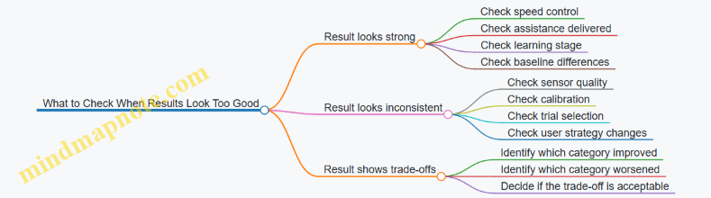
Interpreting results is mostly about fairness: fairness of comparisons, fairness of measurement, and fairness of claims. If you keep those three in view, your conclusions will match what the data can actually support.
10. Safety, Risk Management, and User Protection
10.1 Common Failure Modes and How They Manifest During Use
Exoskeleton walking suits fail in predictable ways because they combine mechanical parts, sensors, and control logic. The tricky part is that a “failure” often looks like a normal walking problem until you notice the pattern.
Actuator and Transmission Issues
Actuators can under-deliver torque, deliver it at the wrong time, or add unwanted resistance.
- Weak or delayed assistance: The user feels like they are “pushing through” the suit. Steps may shorten because the suit stops helping before the foot is planted. Example: during level walking, the user reports that assistance feels strongest for the first few steps, then fades.
- Timing mismatch: Assistance arrives during swing instead of stance. The user may experience toe drag or a sudden push that makes them stumble forward. Example: the suit helps too early, and the user compensates by leaning back.
- Backlash or looseness: Small jerks appear at joint transitions. Example: at each step, the knee support “clicks” and the user’s cadence becomes uneven.
- Over-resistance: The suit fights the user’s motion. Example: when the user tries to slow down, the suit keeps applying resistance, forcing longer, stiffer steps.
Sensor Dropouts and Misreadings
Sensors rarely fail completely; more often they drift, saturate, or intermittently disconnect.
- IMU dropout or reset: The suit suddenly changes its sense of orientation. Manifestation: the user feels a brief loss of smoothness, then the suit “re-centers” and walking becomes choppy for a few steps. Example: turning left feels fine until the suit abruptly corrects posture.
- Encoder glitches: Joint angle readings jump. Manifestation: the controller commands a correction that the user didn’t ask for. Example: ankle assistance spikes when the foot is still on the ground.
- Force sensor saturation: The suit can’t interpret load correctly. Manifestation: stance detection becomes unreliable, so assistance toggles too often. Example: the suit alternates between helping and not helping every other step.
- Calibration drift: The suit’s mapping between sensors and body joints becomes slightly wrong. Manifestation: the user’s alignment feels “off” even though the suit is still strapped correctly. Example: the user develops hip discomfort after a session because the suit’s assumed joint center is shifted.
Control Logic and Gait-Phase Errors
Even with good sensors, phase detection and switching can be wrong.
- Wrong gait phase classification: The suit applies stance torque during swing or vice versa. Example: during a step over a small obstacle, the suit treats the obstacle clearance as stance and resists the leg lifting.
- Assist-as-needed threshold errors: Assistance triggers too easily or not at all. Example: the suit helps when the user is merely shifting weight, causing a “pull” that makes the user overcorrect.
- State machine stuck: The suit keeps repeating the same internal state. Manifestation: repeated hesitation at the same point in the step cycle. Example: every time the user initiates walking, the suit delays assistance for several seconds.
Safety System and Fault Handling Problems
Safety features are designed to stop harm, but they can also create confusing behavior.
- Overly sensitive fault detection: The suit pauses frequently. Example: a minor cable movement triggers a stop, and the user must restart repeatedly.
- Fault not detected: The suit continues operating despite a problem. Manifestation: gradual worsening rather than an immediate stop. Example: assistance becomes less predictable over time as a sensor degrades.
- Emergency stop behavior: Sudden loss of support can destabilize the user. Example: if the suit drops torque instantly during a mid-stance correction, the user may need a handrail to recover.
Mechanical Fit, Interface, and Skin-Related Failures
Poor fit can look like a control problem.
- Pressure hotspots: The suit concentrates load at one spot. Manifestation: discomfort appears early and increases with each step. Example: a strap shift during walking creates a burning sensation at the same location.
- Slippage at liners or cuffs: Relative motion changes sensor readings and joint alignment. Example: the knee brace slowly migrates, and assistance becomes mis-timed.
- Loose fasteners: Micro-movement changes alignment. Example: the user hears a rattle and then notices the suit “fights” their knee extension.
Mind Map: Common Failure Modes and Their Manifestations
Case Study: Intermittent Assistance That Feels Like “It’s There, Then It Isn’t”
A user reports that assistance is helpful for the first minute, then becomes inconsistent. During observation, the suit pauses briefly without a full stop. The likely chain is sensor dropout causing stance detection to toggle, which triggers fault handling that reduces assistance rather than shutting down. The practical check is to verify cable strain relief and connector seating, then repeat the walk while watching for repeated micro-pauses tied to the same step phase.
Case Study: Toe Drag During Turns
During turning, the user experiences toe drag only when rotating. The suit may be misclassifying phase during lateral weight transfer, or the ankle assistance timing may be shifted by slippage at the cuff. A useful indicator is whether the toe drag correlates with a strap movement or with a consistent step phase during the turn. Fixing fit first prevents chasing a control explanation for a mechanical cause.
10.2 Fall Prevention Practices and Supervision Requirements
Fall prevention for exoskeleton walking suits is a system job, not a “be careful” job. The goal is to reduce the chance of a stumble, stop the suit from making a bad situation worse, and ensure a human is present when the user needs help.
Supervision Levels That Match Risk
Supervision should scale with the user’s current ability and the environment. A practical approach is to define three levels:
- Level 1: Standby supervision when the user can walk the planned route with minimal cueing. The supervisor stays close enough to intervene within a few steps.
- Level 2: Active supervision when the user needs frequent cueing, has inconsistent gait, or is learning a new mode like stairs or uneven surfaces. The supervisor positions to support balance and prevent a fall.
- Level 3: Assisted supervision when the user cannot reliably recover from a misstep. A second person may be needed for physical support while the primary supervisor monitors the suit.
Example: In a clinic hallway, a Level 1 session might be short, straight walking on a flat surface. A Level 2 session might include turning and speed changes. A Level 3 session might be first-time sit-to-stand practice.
Pre-Walk Checks That Prevent “Small Failures”
Most falls start with avoidable setup issues. Before each session, verify:
- Fit and alignment: straps secure without pinching, joint axes roughly match the user’s joints, and the suit does not shift during a test step.
- Sole and foot interface: shoes are stable, footplates are seated correctly, and there is no excessive play that could cause unexpected toe drag.
- Assist mode selection: the intended mode matches the task, and the user knows what changes when the mode changes.
- Emergency stop access: the user and supervisor can reach the stop quickly without stepping into the user’s path.
- Environment readiness: clear floor hazards, adequate lighting, and a route that avoids sudden transitions like rugs or thresholds.
Example: If a user’s shoe laces loosen, toe clearance can degrade. A quick pre-walk “heel-to-toe wiggle test” on the shoe and foot interface can catch that before the first assisted step.
During-Walk Practices That Reduce Recovery Time
When a misstep happens, the time to stabilize matters. Use practices that shorten the recovery loop:
- Keep a consistent walking corridor so the user does not drift into obstacles during turns.
- Use short, specific cues tied to observable events, like “pause” when the foot is off the ground or “hold” when the user is leaning.
- Watch the earliest warning signs: foot scuffing, uneven step timing, sudden trunk stiffening, or repeated near-misses at the same point.
- Avoid sudden user actions like abrupt stopping unless the control system supports it safely.
Example: If the user repeatedly scuffs the toe near the end of a session, the supervisor can reduce walking duration, adjust assistance intensity, and check fatigue-related changes rather than pushing through.
Supervision Positioning and Communication
Supervisors should position themselves to support balance without interfering with the suit’s motion.
- Side support for balance: stand slightly behind and to the side where you can catch a lateral loss of stability.
- Front awareness: keep the path clear and monitor where the feet will land, especially during turns.
- Clear handoff rules: decide who controls the emergency stop and who provides physical support.
Communication should be simple and consistent. Agree on a small set of commands before the session, such as “stop,” “hold,” and “reset,” and use them the same way every time.
What to Do When a Fall Risk Event Occurs
A fall risk event can be a stumble, a loss of balance, or a suit behavior that does not match the user’s intent. The response should be structured:
- Stop the walking task if the user’s balance is compromised or if the suit is not tracking the intended gait.
- Stabilize the user before attempting to resume assistance.
- Check the cause: fit shift, foot interface slip, fatigue, or incorrect mode.
- Reset safely: re-calibrate or re-fit if needed, then restart with a reduced challenge.
Example: During a turn, the user’s foot lands slightly off-target and the trunk leans. The supervisor calls “stop,” supports the user’s torso, and pauses suit assistance. After stabilizing, they check whether the footplate seated correctly and whether the turn speed was too high.
Mind Map: Fall Prevention and Supervision
Example Scenarios with Clear Decisions
Scenario 1: Toe Scuffing Appears The user starts scuffing near the same point. The supervisor stops the task, checks shoe seating and footplate alignment, reduces walking duration, and restarts in a simpler mode.
Scenario 2: Sudden Trunk Lean During Turning The supervisor calls “stop,” supports the user’s torso, and prevents the user from continuing the turn. After stabilization, they verify that the suit mode matches turning practice and that the user’s stance width is appropriate.
Scenario 3: User Requests to Continue After a Near-Miss The supervisor does not treat the near-miss as “fine.” They pause, assess fatigue and footing consistency, and decide whether to end the session or restart with reduced challenge.
Practical Rules That Keep Everyone Grounded
Supervision is effective when it is predictable. Use rules like these:
- If balance is uncertain, stop before you correct.
- If the suit behavior seems wrong, check setup before changing everything.
- If the user is learning, reduce task complexity rather than increasing assistance intensity.
These practices keep the system stable, the user safe, and the team aligned on what “good” looks like during walking.
10.3 Skin Injury Prevention and Pressure Reassessment Schedules
Skin injury risk in walking suits comes from two predictable sources: sustained pressure that reduces blood flow, and shear forces that rub the skin during motion. The goal of prevention is not “never get red,” but to keep pressure and friction within tolerable limits and to catch problems early—before they become painful or persistent.
Pressure Injury Basics You Can Act On
Start with a simple rule: pressure is time-dependent. A spot that looks acceptable for a few minutes can become a problem after an hour, especially if the user is sweating or the liner is slightly misaligned. Shear is the second rule: if the skin is dragged relative to the liner during gait, redness can appear even when average pressure seems moderate.
Practical implication: you need both a fit check and a schedule. Fit checks catch alignment issues; schedules catch time-related changes.
Fit and Interface Practices That Reduce Risk
Use a consistent donning routine so the liner ends up in the same place every session. For example, align the liner seams with anatomical landmarks, then tighten straps in a cross pattern rather than pulling one side until it “feels right.” If the suit has adjustable cuffs, set them to a snug baseline first, then fine-tune after a short walk.
Pressure hotspots usually cluster at bony prominences and along strap paths. Common examples include the tibial area near the shin, the lateral knee region, the malleoli around the ankles, and the iliac crest region at the hip. Treat these as “check first” zones rather than waiting for discomfort.
A quick self-check after donning: ask the user to perform gentle knee bends and ankle flexion while standing still. If any area shifts relative to the skin, you likely have shear. Reduce shear by improving liner placement, using anti-slip layers where appropriate, and avoiding over-tightening that causes the liner to buckle.
Pressure Reassessment Schedules That Match Real Sessions
Use a two-layer schedule: an early check for donning errors and a later check for time effects. The exact timing depends on session length and intensity, but the structure should stay consistent.
Baseline schedule for typical training sessions (30–60 minutes):
- At 5 minutes: Inspect strap lines and bony points. Look for early redness, whitening, or uneven marks.
- At 15 minutes: Re-check any area that showed early color change. Confirm the user can feel normal sensation.
- At 30 minutes: Perform a full interface scan. Pay attention to areas that experience repeated loading during walking.
- At session end: Inspect again, then document findings immediately.
Extended sessions (60–120 minutes):
- At 5 minutes and 15 minutes as above.
- Every 30 minutes thereafter: Do a targeted scan of hotspots plus any new red areas.
- At session end: Full scan and documentation.
High-intensity or new-program sessions:
If the user is doing stairs, longer bouts, or a new assistance mode, shorten the early checks. Use 2 minutes and 10 minutes for the first two inspections, then follow the standard schedule.
What to Look for During Reassessment
Redness is not the only signal. Use a simple observation set:
- Color change: persistent redness, blotching, or a pattern matching strap placement.
- Texture and temperature: warmth can indicate irritation; coolness can indicate reduced circulation.
- Sensation changes: numbness, tingling, burning, or “hot spots” that appear during walking.
- Skin integrity: any blistering, cracking, or open areas are stop conditions.
If the user reports discomfort, treat it as data. Stop the session, loosen to a safe baseline, and re-check alignment before continuing.
Decision Rules for Stopping and Adjusting
Use clear thresholds so the schedule actually prevents injury.
- Stop immediately if there is open skin, blistering, sharp pain, or rapidly worsening sensation.
- Pause and adjust if redness appears in the same hotspot across two checks, or if redness spreads beyond the strap path.
- Continue with caution only if color change is mild, sensation is normal, and the area does not worsen at the next scheduled check.
After adjustment, restart with a short “test walk” (about 3–5 minutes) and re-check at the next scheduled time.
Documentation That Makes Future Sessions Safer
Record what you can reproduce: where the issue was, what the user felt, and what you changed. A useful log entry includes:
- Session date and duration
- Suit configuration and assistance mode
- Donning time and reassessment times
- Hotspot locations and skin observations
- Strap tension changes or liner repositioning
- Outcome at session end
This turns “it felt fine last time” into a trackable pattern.
Mind Map: Skin Injury Prevention and Pressure Reassessment
Example: A Realistic Session with Reassessment
A user trains for 45 minutes. At 5 minutes, the clinician notices mild redness along the strap line over the lateral shin. At 15 minutes, the redness is slightly darker but sensation is intact. The clinician pauses, loosens the strap to the baseline setting, repositions the liner seam, and performs a 4-minute test walk. At 30 minutes, the redness is reduced and remains confined to the strap path. The session ends with a full scan showing no blistering, and the log notes the strap repositioning as the effective change.
This approach prevents the “wait and see” pattern that turns a manageable irritation into a session-ending injury.
10.4 Emergency Procedures and Safe Shutdown Protocols
A walking suit should fail in a way that keeps the user stable and reduces the chance of skin injury. Emergency procedures are not just “press a button and hope”; they are a sequence that quickly removes assistance forces, prevents runaway motion, and makes the system safe to approach.
Emergency Priorities
- Stop motion that could destabilize the user. Assistance should disengage fast enough that the user can regain their own balance.
- Remove or limit stored energy. Motors, brakes, and power electronics should move to a safe state.
- Make the suit safe to touch. Reduce risk of pinch points, hot components, and unexpected re-engagement.
- Preserve evidence for troubleshooting. Record what happened so the next session can be safer.
Emergency Stop Triggers
Use multiple triggers so the user does not need perfect timing.
- User-accessible stop button on the controller or suit.
- Loss of key signals such as gait-phase estimate confidence dropping below a threshold.
- Actuator fault detection like motor current spikes, encoder disagreement, or unexpected torque commands.
- Communication loss between controller and motor drives.
Example: If the suit detects that hip torque commands do not match measured joint motion, it should stop assistance and switch to a passive mode rather than continuing to “push harder.”
Safe Shutdown States
Define states so every component agrees on what “safe” means.
- Assistance Off: control outputs go to zero torque or guidance limits.
- Hold or Passive: either brakes engage (if designed for it) or the suit becomes compliant.
- Power Down: motor drive enable lines are disabled; high-voltage rails are shut down.
- User-Approach Safe: fans stop, but temperature monitoring remains active until components cool.
Step-By-Step Actions During Use
If the user feels unstable or hears an unusual mechanical sound:
- Press the emergency stop or use the designated stop gesture if available.
- Adopt a stable stance: pause with feet planted, then sit if a seat is nearby.
- Keep hands clear of moving joints while the suit transitions to Assistance Off.
- Wait for confirmation from the controller indicator that the system is in a safe state.
Example: During a hallway walk, the user notices the knee assistance feels “late.” Pressing stop should remove torque commands immediately, allowing the user to take a controlled step or sit.
If the suit stops unexpectedly:
- Do not restart immediately. Treat it as a safety event.
- Check footing and environment for obstacles or slippery surfaces.
- Verify fit and alignment at the most likely interfaces (thigh and shank cuffs) before attempting a reset.
Caregiver and Clinician Actions
Caregivers often need a clear rule: approach only after motion is disabled.
- Confirm the suit is not applying assistance. Look for the Assistance Off indicator.
- Support the user first, then inspect. Stabilize the user before adjusting straps.
- Inspect for pinch or pressure points at the last known contact locations.
- Avoid repeated resets. If faults persist, the session should end.
Example: If a caregiver sees redness forming under a cuff, they should stop further attempts to resume and document the time and location.
Verification and Reset Rules
A reset should be allowed only when the system can prove it is safe.
- Confirm stop state: controller reports Assistance Off and motor drives disabled.
- Check thermal and power limits: do not restart if thermal sensors indicate overheating.
- Inspect mechanical constraints: ensure nothing is caught in linkages or straps.
- Review fault logs: identify whether the trigger was sensor, actuator, or power related.
Reset guidance example:
- If the fault is temporary communication loss, a single reset may be allowed.
- If the fault is actuator overcurrent or encoder mismatch, do not reset without a full inspection.
Common Scenarios with Concrete Responses
Unexpected Leg Swing
- Trigger: joint motion diverges from commanded assistance.
- Response: emergency stop, then wait for passive mode; check for loose cuffs or obstruction.
Skin Pressure Alarm
- Trigger: pressure sensor indicates sustained high load.
- Response: Assistance Off, reposition the liner/cuff, and verify that the suit is aligned with the joint center.
Battery or Thermal Limit Reached
- Trigger: power management reduces output or disables drives.
- Response: stop walking when assistance reduces, sit or hold support, then power down if instructed by the system.
Controller Reboot Mid-Session
- Trigger: software restart.
- Response: treat as Assistance Off until the controller completes initialization checks; do not resume until indicators confirm readiness.
Documentation That Helps the Next Session
Record four items every time: time, trigger type, user position (standing, seated, supported), and what changed right before the event (strap adjustment, surface change, fatigue level). This keeps troubleshooting grounded in facts rather than memory.
A good emergency protocol is boring in the best way: it tells everyone exactly what to do, in what order, and what “safe” looks like before anyone tries to continue walking.
11. Practical Deployment Scenarios and Setup Checklists
11.1 Home Use Setup and Daily Routine Integration
Home use works best when the suit becomes part of a repeatable routine rather than a special event. The goal is to reduce setup time, prevent avoidable errors, and keep the user’s skin and joints happy.
Home Setup Checklist
Start with a “one-time” setup that you can repeat without thinking.
- Choose a consistent walking space. Use a clear path with stable flooring, good lighting, and a wall or sturdy counter nearby for light support. If you use a walker or cane, keep it in the same spot.
- Set up a staging area. Place the suit components, charger, and any straps/liners where you can reach them without bending awkwardly. A small mat under the staging area helps keep liners clean.
- Mark alignment points. Use removable tape or washable markers on the floor to indicate where the user should stand for donning and where the first steps should begin.
- Prepare a “skin check” station. Keep a mirror, mild cleanser/wipes, and a simple log sheet where you can inspect pressure areas before and after use.
- Confirm emergency access. Ensure the user or caregiver can quickly reach the power switch and any manual release points without stepping over cables.
Donning and Doffing Routine
A consistent order prevents missed straps and reduces the chance of uneven pressure.
- Inspect first. Check liners for wrinkles, tears, or debris. Look for redness from prior sessions.
- Don in a repeatable sequence. Start with the base layer/liners, then attach the frame components in the same order each time.
- Tighten by “snug then settle.” Apply initial snug tension, then do a short standing test to let the fit settle before final adjustments.
- Verify joint alignment. Confirm that the suit’s joint axes line up with the user’s knee/hip motion. If alignment feels off, stop and adjust before walking.
- Doff without yanking. Release straps gradually and support the frame while removing it. This reduces friction and skin irritation.
Daily Routine Integration
Treat the suit like a tool used at a specific time, not something that competes with the day.
- Pick a predictable time window. Many users do better when they’re not rushed and when fatigue is lower. If mornings are hard, choose late morning or early afternoon.
- Use a short pre-walk warmup. Spend 3–5 minutes doing gentle standing weight shifts or assisted stepping without full assistance. This helps the user and suit “agree” on posture.
- Start with a low-assistance session. Begin with the simplest mode and short bouts. The first steps should feel controlled, not forced.
- Plan for rest breaks. Build in pauses for hydration and skin comfort. If the suit supports longer walking, breaks still matter because pressure and muscle effort change over time.
- End with a consistent post-walk check. Inspect pressure points, note any discomfort level, and record whether the session felt easier, harder, or about the same.
Example Home Session Plan
A practical session might look like this:
- 0–5 minutes: Skin check, donning, and a standing posture check.
- 5–10 minutes: Assisted warmup steps near the support surface.
- 10–20 minutes: Three walking bouts of 2–3 minutes with 1–2 minutes of rest.
- 20–25 minutes: Cooldown standing and gentle stretching while seated or supported.
- After: Skin inspection and quick log entry.
If the user reports new pain, the next session should reduce assistance or shorten walking time rather than “pushing through.”
Mind Map: Home Setup and Daily Routine
Common Mistakes and Fixes
- Skipping the standing “settle” step. If straps feel tight immediately but uncomfortable after a few minutes, repeat the settle step before walking.
- Changing the walking start position. If the user starts from a different spot each time, balance and step timing can vary. Use floor markers.
- Ignoring minor skin redness. Mild redness can be a signal to adjust pressure distribution or shorten the next session.
- Overextending the first session. Longer sessions often lead to worse fit tolerance. Short, repeatable bouts usually produce steadier progress.
11.2 Rehabilitation Clinic Workflows and Session Planning
A good clinic workflow makes the exoskeleton feel like part of the session, not the session’s boss. The goal is repeatable setup, predictable assistance, and clear handoff between staff members.
Session Planning Before the Patient Arrives
Start with a short plan that matches the patient’s day, not just the device’s capabilities.
- Confirm the session objective. Pick one primary target, such as “improve step symmetry during level walking” or “practice sit-to-stand with safe knee alignment.” Keep secondary goals small so staff can notice what changes.
- Review the last session notes. Look for patterns: skin redness hotspots, fatigue timing, and whether assistance felt too strong or too weak at specific gait speeds.
- Choose the environment and supports. Decide whether the session is in a parallel bar setup, with a walker, or on a treadmill. Plan the supervision level and who controls the safety harness.
- Pre-stage materials. Have liners, straps, pressure-check supplies, and spare fasteners ready. If you wait for a missing part mid-session, you lose both time and calibration confidence.
Mind Map: Pre-Session Planning
Intake, Safety Checks, and Fitting
Treat fitting as a sequence with checkpoints. If you skip a step, the device may still “work,” but the patient experience will be inconsistent.
- Baseline observation. Watch the patient walk without assistance for a few steps. Note foot clearance, trunk sway, and how quickly they fatigue.
- Skin and comfort screen. Check prior pressure areas and confirm liner fit. If the patient reports numbness or sharp discomfort, pause and adjust before powering the actuators.
- Alignment and joint mapping. Use the clinic’s standard alignment procedure for hip, knee, and ankle interfaces. A small misalignment can create a big mismatch between intended and delivered torque.
- Functional test at low assistance. Run a short “warm-up” sequence: stand, a few steps, and controlled turns if appropriate. Confirm that the suit responds smoothly to gait phase transitions.
Example: A Two-Stage Fitting Flow
A clinic fits the suit in two stages: first, mechanical alignment with the patient standing still; second, dynamic verification during slow walking. If the patient’s foot clearance improves during stage two, the staff logs the settings and proceeds. If not, they adjust ankle alignment and repeat the short test.
Session Structure That Works in Practice
A typical session balances preparation, practice, and evaluation. The timing below is a template; staff adjust based on fatigue and skin tolerance.
- Warm-up and comfort check (5–10 minutes). Confirm comfort after the first active steps. Re-check pressure points if the session starts with a new liner or strap configuration.
- Assisted practice block (15–25 minutes). Use a consistent walking task for most of the block. Change only one variable at a time, such as assistance level or walking speed.
- Skill focus block (10–15 minutes). Switch to a targeted challenge: sit-to-stand repetitions, step-over a low obstacle, or controlled turns.
- Cool-down and debrief (5–10 minutes). Reduce assistance and let the patient walk briefly without it, if clinically appropriate. Record what felt easier, what felt harder, and where discomfort appeared.
Mind Map: In-Session Flow
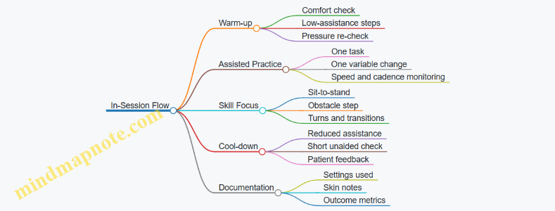
Staffing Roles and Handoffs
Clear roles prevent accidental changes to settings or safety procedures.
- Fitter. Owns alignment, strap tension, and pressure checks.
- Safety lead. Manages harness position, supervision, and immediate risk response.
- Control operator. Adjusts assistance parameters and logs settings.
- Clinician observer. Tracks gait quality and decides when to stop or modify the task.
A simple handoff script helps: “Objective is X. Current settings are Y. Safety plan is Z. Stop criteria are A.” Everyone repeats the stop criteria so the patient is protected even if the control operator is focused on the tablet.
Stop Criteria That Keep Sessions Productive
Stop the session or pause assistance when:
- The patient shows increasing compensations, such as worsening foot drag or sudden trunk leaning.
- Skin redness persists or grows after a brief rest.
- The patient reports pain that changes in intensity or location.
- The suit response becomes inconsistent, such as delayed phase transitions.
Example: Adjusting Without Restarting
If a patient’s step clearance drops halfway through the assisted block, staff first reduce walking speed slightly and confirm phase detection stability. If clearance improves, they keep the same assistance mode and continue. If not, they pause, re-check ankle interface comfort, and repeat the short warm-up test before resuming.
Documentation That Supports Next Sessions
Write notes that help the next person act quickly.
- Settings used. Assistance level, walking speed range, and any mode changes.
- What changed. “Step clearance improved after ankle alignment adjustment” is more useful than “patient did better.”
- Skin and comfort. Location, severity, and time to recover.
- Patient feedback. Specific sensations like “pressure at medial knee” or “effort felt higher during stance.”
Mind Map: Documentation
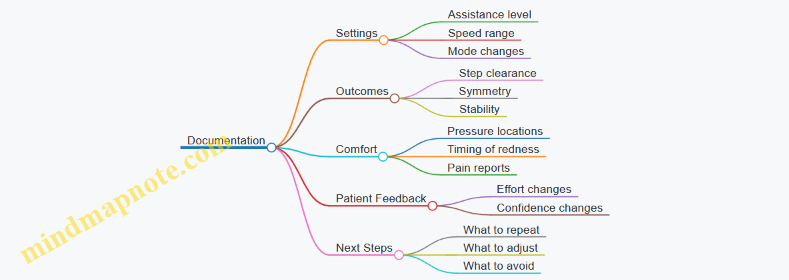
A well-run clinic session ends with a clear trail: what was attempted, what worked, and what needs adjustment. That trail is what turns each session into a controlled experiment rather than a fresh start.
11.3 Workplace Assistance for Mobility Demands
Workplaces add a different kind of complexity: schedules, crowded paths, uneven surfaces, and the need to keep moving even when the day is not going perfectly. A walking suit can help, but only if the setup matches the environment and the user’s routine.
Workplace Demand Mapping
Start by listing the mobility tasks the user actually performs. Then match each task to the suit’s most relevant assistance mode.
- Path walking: long corridors, doorways, and turns.
- Task transitions: reaching a workstation, stepping into a vehicle, or moving from a meeting room to a hallway.
- Surface changes: thresholds, ramps, mats, and outdoor patches.
- Time pressure: short windows between tasks.
A practical best practice is to run a “day-in-the-life” walk-through with the user and a supervisor. Use a simple checklist: where the user slows down, where they stop, and where they feel least stable. Those locations become the training targets.
Setup for Real-World Navigation
Workplace walking is mostly about consistency. The suit should behave predictably at the same points in the day.
- Mark repeatable waypoints: identify the same turning points, entry thresholds, and workstation approach lines.
- Standardize starting posture: begin each session with the same stance and foot placement so the suit’s assistance engages at the right moment.
- Plan for “pause and resume”: many workplaces require stopping briefly. Practice short stops without forcing the user to hold awkward positions.
Example: In an office, the user walks from a desk to a printer area, stops at the printer, then turns back. Training should include the exact turn angle and the typical stop duration. If the user always pauses for about two seconds, practice that pause length so the suit’s assistance doesn’t feel like it “waits” or “pushes.”
Managing Crowds and Shared Space
Crowds change how much clearance the user has. The goal is not to make the suit “stronger,” but to make it easier to control.
- Use conservative assistance thresholds during crowded periods.
- Practice lateral avoidance: step planning matters when someone cuts across the path.
- Keep a buffer: if the user can’t maintain a safe distance, the workplace layout needs adjustment.
Example: In a warehouse aisle, a coworker may approach from the side. Train a routine where the user slows slightly, re-centers, and then continues. This reduces sudden corrections that can cause discomfort or missteps.
Handling Uneven Surfaces and Transitions
Workplaces rarely have perfect floors. The suit must support the user through small changes without surprising them.
- Thresholds and door sills: practice stepping over them at a consistent speed.
- Mats and cables: treat them as obstacles, not as “normal floor.”
- Ramps and slopes: use a controlled approach and avoid rushing.
Example: A hospital corridor may have a rubber mat near a supply room. During training, walk the mat repeatedly and note whether the user’s foot clearance changes. If clearance drops, adjust the suit’s swing support so the toe clears reliably without over-lifting.
Workstation Integration and Task-Specific Assistance
Assistance should match the task, not just the walking.
- Approach and alignment: practice stopping at the correct distance from a workstation so the user can reach without twisting.
- Sit-to-stand cycles: if the job includes frequent chair rises, train those transitions as a separate routine.
- Carrying and hand use: if the user carries items, practice with the same load and grip style.
Example: A lab technician may need to stand up from a stool, walk to a bench, and lean to place a sample. Training should include the bench approach and the lean posture so the suit supports the stance without fighting the user’s natural movement.
Scheduling, Fatigue, and Break Planning
Workplace days are long, and fatigue affects balance and timing.
- Use predictable breaks: schedule short pauses before the user’s stability declines.
- Monitor discomfort early: skin pressure and joint fatigue often show up before the user can explain it.
- Keep a “reset routine”: a consistent sequence for re-checking fit, posture, and comfort.
Example: If the user works a four-hour shift, plan a mid-shift reset that includes a quick pressure check and a brief walking drill in a low-traffic area. This prevents the day from turning into a series of small compensations.
Safety Roles and Communication
Safety works best when responsibilities are clear.
- User: follows the pre-use check and reports discomfort immediately.
- On-site helper or supervisor: knows how to create space and when to pause movement.
- Maintenance contact: handles charging, basic inspection, and reporting faults.
Case Study
A manufacturing floor includes a narrow aisle, a doorway threshold, and a mat near a packing station. The user trained on three routes: aisle-to-door, door-to-mat, and mat-to-packing station. During the first week, the user reported toe catching on the mat during rushed steps. The team reduced walking speed during mat crossings and adjusted swing support so toe clearance improved without increasing effort. After that, the user’s stop-and-go behavior became more consistent, and the supervisor reported fewer near-misses when coworkers approached from the side.
Practical Checklist for the First Workday
- Confirm fit and pressure comfort before leaving the break area.
- Walk the route once at a controlled pace, including the doorway threshold.
- Practice one short pause at the workstation approach point.
- Identify where the user will take the first break and what “reset” includes.
- Agree on a simple signal for “pause now” when space is unsafe.
11.4 Transport, Storage, and Pre-Use Inspection Procedures
Transporting and storing a walking suit is mostly about two things: keeping alignment predictable and preventing wear from turning into surprises. A good routine makes the suit behave the same way every time you put it on, even if the day starts with a different hallway, a different floor, or a different helper.
Transport Procedures That Preserve Alignment
Start with a plan for how the suit will be carried. Use a rigid or semi-rigid case that supports the frame at multiple points so the joints do not hang from cables or straps. If the suit uses removable batteries, remove them before moving the suit; it reduces weight and prevents accidental contact with charging pins.
Secure the frame so it cannot shift inside the case. Loose movement during transport can loosen fasteners and change how the limb interfaces sit on the user. A simple check is to gently try to move the frame by hand inside the case; if you can feel shifting, the case needs better padding or tie-down points.
Protect the cable runs and connectors. Route cables so they cannot be pinched by latches or pressed against hard edges. If the suit includes quick-connect plugs, keep them capped or covered when disconnected to reduce dust and skin-oil buildup.
Example: A clinic transports two suits in rolling carts. Each suit has a dedicated insert foam shape. The therapist places the suit so the hip and knee modules rest on the insert, then uses two straps to prevent side-to-side movement. The battery is stored separately in a labeled pocket.
Storage Conditions That Prevent Slow Damage
Store the suit in a dry, temperature-stable space. Moisture can affect sensors and cause corrosion on metal parts, while extreme heat can degrade battery performance and adhesives. Keep the suit off the floor when possible, using a shelf or rack.
Avoid storing the suit with joints under tension. If the suit uses straps to hold limbs in a particular position, loosen them for storage so the mechanism is not constantly loaded. For suits with adjustable components, set them to a neutral position that matches typical fitting ranges, then lock adjustments so they do not drift.
Keep liners and contact surfaces clean and dry before storage. If the suit has been used with sweat, wipe contact areas and allow them to air-dry fully before closing the case. Trapped moisture is the enemy of comfort and skin safety.
Example: After a session, the clinician wipes the thigh and shank interfaces, removes the liner if it is designed to be removable, and lets it dry on a rack. The suit goes into storage only after the contact surfaces feel dry to the touch.
Pre-Use Inspection Procedures That Catch Issues Early
A pre-use inspection should take minutes, not an hour, and it should be consistent. Use a checklist that covers mechanical integrity, electrical readiness, and fit-related wear.
1. Visual and Mechanical Check
- Inspect frame fasteners for looseness.
- Check that joint covers and protective guards are seated.
- Look for frayed cables, cracked insulation, or exposed wiring.
- Verify that footplates and any ankle or toe components move freely without grinding.
2. Connector and Cable Check
- Confirm connectors are clean and fully seated.
- Check cable strain reliefs are intact and not stretched.
- Ensure no cable is routed across a sharp edge.
3. Sensor and Actuator Readiness
- Power on and observe system status indicators.
- Run the suit’s built-in self-test if available.
- If the suit supports a calibration step, confirm it is due and that the last calibration date is logged.
4. Interface and Comfort Check
- Inspect liners for wrinkles, thinning, or tears.
- Check pressure-contact areas for hard spots or residue.
- Confirm straps and buckles hold securely and release smoothly.
5. Battery and Power Check
- Verify battery charge level meets the session length.
- Check battery contacts for dirt or discoloration.
- Confirm the battery is locked in place before moving the suit.
Example: During a clinic morning, a therapist notices a slight cable twist near the knee module. The suit is not used until the cable is re-routed and secured with the intended clips. The therapist logs the issue so maintenance can inspect the cable path later.
Mind Map: Transport, Storage, and Pre-Use Inspection
Quick Checklist You Can Actually Use
- Case supports the frame; nothing hangs from cables.
- Battery removed for transport; connectors protected.
- Stored dry; contact surfaces fully dry.
- Fasteners, guards, and foot components look intact.
- Cables are unfrayed, unpinched, and properly seated.
- Self-test passes; calibration is current.
- Liners and straps are clean, intact, and secure.
- Battery charge covers the session.
Example: A home-care aide follows the checklist in the same order each time. If any step fails, the suit is set aside with a note describing what was observed, so the next person does not waste time guessing.
12. Human Augmentation Boundaries and Ethical Use in Mobility
12.1 Distinguishing Medical Assistance From Augmentation Claims
Exoskeleton walking suits can be used to help people move, but the language around them matters. “Medical assistance” describes support aimed at treating a condition, improving function, or reducing impairment in a way that aligns with clinical goals. “Augmentation” describes enhancement beyond a person’s typical baseline, often framed as adding capability rather than addressing a limitation. The same hardware can be used in both contexts, so the distinction comes from the claim, the intended user outcome, and the evidence you would need to justify it.
What Counts as Medical Assistance
A medical assistance claim is tied to a health-related problem and a measurable functional improvement. The suit is presented as helping with mobility limitations caused by injury, disease, or disability. The key is that the target outcome is not “more” in general; it is “better” relative to a specific impairment.
Easy example: A clinic uses a suit to help a person with foot drop clear the ground during swing. The claim focuses on reducing trips and improving safe walking distance for that user group.
Practical test: If the claim would still make sense when the user’s baseline is reduced by a known impairment, it leans medical. If it instead assumes a healthy baseline and promises added performance, it leans augmentation.
What Counts as Augmentation
An augmentation claim emphasizes capability expansion. It may target speed, endurance, load-carrying, or reduced effort in ways that are not framed as restoring function after impairment. Even if the suit helps someone feel less tired, the claim becomes augmentation when the goal is framed as exceeding typical human performance rather than addressing a clinical limitation.
Easy example: A suit is described as enabling able-bodied users to walk longer distances with less fatigue than they normally can, without reference to a medical condition.
Practical test: If the claim’s primary audience is people without mobility impairments and the main outcome is “extra ability,” it leans augmentation.
The Claim-Outcome Link
Claims should match the outcome you can reasonably measure. Medical assistance claims usually specify functional targets such as gait safety, walking independence, or reduced effort for a defined impairment. Augmentation claims often specify performance targets such as higher step rate, longer duration, or greater load tolerance.
A helpful way to keep this straight is to write the claim as a single sentence with three parts: who it’s for, what limitation or baseline it addresses, and what outcome changes.
Example of a medical-style sentence: “For people with impaired ankle dorsiflexion, the suit assists swing-phase foot clearance to reduce tripping during community walking.”
Example of an augmentation-style sentence: “For healthy users, the suit increases walking endurance by reducing muscular effort during prolonged walking.”
Evidence Expectations
Medical assistance claims typically require evidence that the suit improves function for the relevant condition and that the improvement is clinically meaningful. That includes safety outcomes like skin integrity and fall risk, plus functional outcomes like step clearance or sit-to-stand success.
Augmentation claims typically require evidence that the suit improves performance metrics beyond typical baseline, often including comparisons to unaided walking under controlled conditions.
The same study design can serve either purpose, but the interpretation changes. If you measure reduced effort in a group with a specific impairment, you can justify medical assistance. If you measure increased capacity in a group without impairment and frame it as exceeding normal ability, you justify augmentation.
Mind Map: Distinguishing Claim Types
Case Examples That Stay Grounded
Case Study: Foot Clearance Support A rehabilitation program uses the suit to assist swing-phase motion for a person with neurological impairment. The program tracks reduced trips and improved walking consistency. The claim is medical because it addresses a specific mobility limitation and uses outcomes tied to safety and function.
Case Study: Longer Walk Without Fatigue A study recruits participants without mobility impairments and measures longer walking duration with lower perceived effort. The claim is augmentation because it targets performance capacity rather than restoring function after a defined impairment.
A Simple Checklist for Writers and Clinicians
- Name the user group: impairment-related or general baseline.
- State the limitation or baseline: what is being compensated for.
- Define the outcome: safety and functional improvement versus performance expansion.
- Match evidence to the claim: clinical relevance for medical, performance comparison for augmentation.
- Avoid mixed messaging: if you claim medical assistance, don’t center the narrative on “more capability” as the primary goal.
When the claim is precise, the suit’s role becomes clear. The hardware can be the same; the meaning comes from what problem it is meant to solve and how success is measured.
12.2 User Consent, Training Requirements, and Informed Use
User consent is not a signature at the end of a form. It is an ongoing agreement that the person understands what the suit will do, what it will not do, and what responsibilities come with wearing it.
Informed Consent That Actually Covers the Basics
Start with plain-language explanations of three topics: purpose, limits, and risks. Purpose means the specific assistance the suit provides, such as supporting knee extension during stance or helping foot clearance during swing. Limits means what the suit cannot guarantee, like preventing all falls or replacing physical therapy goals. Risks include skin pressure, fatigue from wearing a device, and loss of balance if the user ignores guidance.
A good consent process also clarifies who is responsible for what. The user is responsible for reporting discomfort, following training steps, and using the suit only in approved environments. The clinician or trainer is responsible for fitting accuracy, initial settings, and safety checks. The manufacturer or support team is responsible for documented procedures and maintenance guidance.
Example: A user agrees to use the suit for short indoor walks with a spotter. The consent should state that using it alone on stairs is not covered by the agreement, even if the user feels capable.
Training Requirements That Match Real Use
Training should be staged so the user earns each capability. The goal is not to “get comfortable fast,” but to build reliable habits that reduce surprises.
-
Fit and comfort training: The user learns how the suit should feel, what pressure points are acceptable, and how to stop use if pain appears. Practice includes tightening/loosening straps to a target feel and checking alignment marks.
-
Static control training: The user practices standing still while the suit holds posture assistance. This teaches the user to notice unusual sensations and to use an agreed stop command.
-
Assisted walking training: The user practices short steps with a trainer controlling speed and assistance level. The user learns how to initiate walking, how to pause, and how to recover from a stumble without grabbing random parts.
-
Task-specific training: Only after stable walking is mastered does the user practice sit-to-stand, turning, or uneven surfaces, each with explicit boundaries.
Example: If turning is part of the user’s goals, training should include turning at multiple speeds and directions, because turning changes joint timing and balance demands.
Informed Use Rules That Prevent “Accidental Experiments”
Informed use means the user knows the operational rules and why they exist. Rules should be written as actions, not warnings.
- Use the suit only in the environment it was trained for. If training was done in a hallway with hand support, the user should not switch to open spaces without supervision.
- Stop when the suit behavior changes. The user should recognize signs like unexpected assistance, delayed response, or new pressure sensations.
- Follow the supervision plan. If a spotter is required for the first weeks, the user should not treat “I feel fine today” as a permission slip.
- Maintain the agreed device checks. Pre-use checks include battery status, strap condition, and quick inspection for loose components.
Example: A user notices the suit is assisting more strongly than usual. In informed use, the correct action is to stop and request a settings check, not to “test it for a few more steps.”
Mind Map: Consent, Training, and Informed Use
Case Example: A Consent Conversation That Reduces Confusion
A trainer explains that the suit will help with knee support during stance and foot clearance during swing, but it will not prevent tripping over objects. The trainer then demonstrates the stop command and asks the user to repeat it while standing still. Next, the trainer runs a five-minute walking session with a fixed route and a clear end condition.
After the session, the trainer asks the user to state three things: the purpose of the suit for this plan, the rule for stopping, and the environment where it is allowed. If any answer is vague, training repeats before the user is cleared to walk without a spotter.
This approach treats consent as a skill the user demonstrates, not a document the user signs.
12.3 Privacy and Data Handling for Sensor-Driven Systems
Exoskeleton walking suits collect data because they need to know where the user is, what the user is doing, and how much assistance to apply. Privacy work starts by treating that data as personal health information, even when it seems harmless—like a time series of joint angles.
Data Inventory and Purpose Limits
Begin with a plain-language inventory of every data stream: inertial measurements, joint encoder readings, force/torque estimates, pressure maps from liners, battery status, and any logs from the controller. For each stream, write a single purpose statement such as “detect gait phase to time assistance” or “monitor pressure to prevent skin injury.” If a stream has no purpose, it should not be collected.
A practical best practice is to separate “control data” from “recording data.” Control data is used immediately to stabilize walking and can often be processed on-device without saving raw signals. Recording data is stored for clinical review or troubleshooting and should be minimized to what is actually needed.
Example: A clinic may only need step-level summaries (step count, average cadence, assistance level) rather than raw high-frequency sensor traces. Summaries reduce exposure while still supporting outcome tracking.
Data Minimization and Retention
Minimization means collecting fewer fields, at lower resolution, or for shorter durations. Retention means defining how long each category is kept and what happens afterward.
A useful rule of thumb: store raw sensor streams only when there is a specific reason, such as investigating a reported discomfort pattern. Otherwise, store derived metrics and keep raw data for a short window.
Example: After a training session, keep gait summaries for 12 months for longitudinal progress, but delete raw IMU and pressure traces after 30 days unless the user requests a review.
On-Device Processing and Access Control
Whenever possible, compute assistance decisions locally. That reduces the amount of sensitive data that ever leaves the suit. When data must be transferred—such as for clinician dashboards—use strict access control.
Access control should include authentication for staff accounts, role-based permissions (clinician vs. technician vs. admin), and audit logs that record who accessed what and when. Audit logs are not for blame; they are for accountability when something goes wrong.
Example: A technician can view device health logs but cannot view pressure maps tied to a specific user profile unless a clinician has granted permission for that session.
Consent, User Choice, and Transparency
Consent should be specific to data categories and actions. Users should know whether data is used for immediate operation only, stored for clinical review, or shared with caregivers or support staff.
Transparency also includes describing what is not collected. If the system does not record video or location, say so clearly in the user-facing documentation.
Example: A user may agree to store step summaries for therapy progress but decline storage of raw pressure traces. The system should still function and should not silently override the preference.
De-Identification That Actually Helps
De-identification is not the same as anonymization. Removing names from files is a start, but sensor data can still be identifying because it reflects a person’s movement patterns.
A more reliable approach is to separate identifiers from data at the storage layer. Use pseudonymous IDs for internal linkage and restrict re-identification to authorized workflows.
Example: Store gait summaries under a random study ID. Keep the mapping between study ID and user identity in a separate, access-restricted database used only for clinical follow-up.
Secure Storage, Transmission, and Backups
Data should be encrypted at rest and in transit. Encryption prevents casual exposure if a device is lost or a network is misconfigured.
Backups require the same protection as primary storage. If backups are less secure, they become the weak link.
Example: If a clinic backs up devices nightly, ensure the backup system uses the same encryption keys and access controls as the main storage.
Handling Logs, Diagnostics, and Error Reports
Logs often contain more information than people expect: timestamps, device identifiers, and sometimes user-linked session metadata. Treat logs as sensitive.
Best practice is to separate operational logs from user-linked clinical data. When sending error reports, include only what is needed to reproduce the issue, and avoid attaching raw sensor streams unless explicitly required.
Example: If a suit reports “sensor saturation during swing,” the error report can include summary statistics and calibration state without attaching full-resolution pressure traces.
Mind Map: Privacy and Data Handling
Case Example: Clinic Session Data Flow
A clinic session starts with on-device processing that computes gait phase and assistance timing. During the session, the suit may store only short-lived buffers needed for control stability. After the session ends, the system saves step summaries and session-level comfort indicators. Raw pressure traces are deleted automatically after the retention window unless a clinician flags the session for review.
If a user declines raw trace storage, the clinician still receives the summaries needed for progress tracking. If an error occurs, the technician receives a diagnostic package that includes device state and summary metrics, not full-resolution personal sensor streams.
This approach keeps the suit effective while reducing the amount of personal data that persists, travels, or sits around waiting for someone to look at it.
12.4 Appropriate Use Criteria and When Not to Use a Suit
Appropriate use criteria are less about “can the suit help?” and more about “can the suit help safely, with the user’s body and environment behaving predictably enough for the control system to do its job.” A good rule is to treat the suit like a powered assistive device that requires stable conditions, correct fit, and consistent user participation.
Core Eligibility Checks
Start with the basics: the user should be able to follow simple instructions, maintain a standing posture long enough for the suit to engage, and tolerate the physical sensations of straps and joint interfaces. If the user cannot reliably communicate discomfort or changes in sensation, the risk of skin injury and incorrect assistance increases.
Next, confirm that the user’s mobility goal matches the suit’s intended assistance. A device designed for overground walking assistance is not the right tool for tasks that require frequent rapid direction changes, aggressive turning, or complex multi-step maneuvers without supervision.
Finally, verify that the user’s gait deviations are within the suit’s typical operating envelope. For example, if the suit expects a certain hip-knee coordination pattern to time assistance, a user with severe, highly variable stepping patterns may receive assistance at the wrong moment.
When Not to Use a Suit
Avoid use when any of the following conditions are present:
- Unstable medical status during the session. If blood pressure is unstable, dizziness is present, or there is an acute pain flare that changes how the user bears weight, the suit’s assistance may amplify instability.
- Inability to maintain safe stance during engagement. If the user cannot stand with minimal support for the first seconds of assistance, the suit should not be activated.
- Significant skin integrity issues. Open wounds, severe irritation, or numbness that prevents the user from detecting pressure points are stop signs.
- Incorrect fit or unresolved alignment. If joint axes do not align with the user’s anatomy, the suit can create shear forces at the wrong locations.
- Uncontrolled environment. Slippery floors, uneven surfaces without supervision, cluttered walk paths, and poor lighting increase fall risk.
- Unreliable device readiness. If sensors are miscalibrated, the system reports repeated faults, or the user experiences unexpected assistance, stop and troubleshoot before continuing.
A practical mindset: if you cannot explain why the suit should behave correctly in the next 10 seconds, do not use it.
Decision Mind Map
Mind Map: Appropriate Use Criteria and When Not to Use a Suit
Example Scenarios with Clear Outcomes
Example: First-time session in a clinic hallway. The user can follow cues, stands with minimal support, and reports discomfort promptly. The floor is dry, lighting is good, and the suit passes pre-use checks. Outcome: use is appropriate, with supervision and a short engagement trial.
Example: User reports new dizziness mid-session. The user can still stand, but the symptom is new and changes how they distribute weight. Outcome: stop assistance immediately, reassess medically, and resume only when symptoms are stable.
Example: Skin redness after 15 minutes. The user notices burning at a strap edge and the clinician sees persistent redness. Outcome: stop, adjust fit and pressure distribution, and do not continue until the skin condition is resolved or cleared by the care team.
Example: Sensor fault during step timing. The suit intermittently mis-times assistance, causing the user to feel a push at the wrong moment. Outcome: stop use, re-check calibration and sensor connections, and only restart after the timing is consistent.
Example: Home use on a wet kitchen tile. The user wants to practice walking, but the surface is slick and the path includes obstacles. Outcome: do not use; choose a safer route or reschedule.
Practical “Stop Now” Rules
Use a short list that everyone involved can apply without debate:
- Stop if the user cannot safely stand during engagement.
- Stop if assistance feels clearly wrong in timing or direction.
- Stop if new pain, numbness, or pressure hotspots appear.
- Stop if faults repeat or sensors lose reliable readings.
- Stop if the environment changes to increase slip or trip risk.
These rules keep the focus on immediate safety rather than interpreting what “might be happening.” The suit can be helpful, but only when the conditions for predictable, controlled assistance are met.