Future Ultrafast Laser Applications in Smart Industry
1. Introduction to Ultrafast Lasers in Smart Industry
1.1 Fundamentals of Ultrafast Laser Technology
Ultrafast lasers produce pulses of light with durations typically in the femtosecond (10⁻¹⁵ seconds) to picosecond (10⁻¹² seconds) range. These extremely short pulses allow energy to be delivered to a material in a very brief time, concentrating power and enabling precise interactions with matter.
Key Concepts
- Pulse Duration: The length of time each laser pulse lasts. Ultrafast lasers operate in femtoseconds to picoseconds, much shorter than traditional continuous wave or nanosecond lasers.
- Repetition Rate: How often pulses are emitted, usually measured in kilohertz (kHz) to megahertz (MHz).
- Peak Power: The maximum power during a pulse, which can be very high due to the short pulse duration, even if average power is moderate.
- Wavelength: The color or photon energy of the laser light, which affects absorption and interaction with materials.
How Ultrafast Lasers Work
Ultrafast lasers typically use mode-locking techniques to generate a train of short pulses. Mode-locking synchronizes the phases of different frequency modes within the laser cavity, causing constructive interference at regular intervals and producing pulses much shorter than the cavity round-trip time.
Mind Map: Basic Components of an Ultrafast Laser
Interaction with Materials
Because pulses are so short, energy is deposited faster than heat can diffuse, minimizing thermal damage. This leads to “cold” ablation, where material removal occurs with limited melting or collateral damage. This precision is valuable for micro- and nano-scale processing.
Example: Ultrafast Laser Micromachining
A femtosecond laser pulse can create micro-holes in a metal foil with diameters of a few micrometers and minimal heat-affected zones. This contrasts with longer pulse lasers, which tend to melt surrounding areas, causing deformation.
Pulse Energy and Average Power
The energy per pulse (measured in microjoules to millijoules) and the repetition rate together determine the average power. For example, a 1 mJ pulse at 1 kHz repetition rate yields 1 watt average power. Adjusting these parameters affects processing speed and quality.
Mind Map: Laser Parameters and Their Effects
Types of Ultrafast Lasers
- Ti:Sapphire Lasers: Tunable around 800 nm, widely used for research and industrial applications.
- Fiber Lasers: Compact, robust, often operating near 1 µm wavelength.
- Ytterbium Lasers: High average power, suitable for industrial micromachining.
Example: Fiber Laser in Industry
A fiber-based ultrafast laser can be integrated into a manufacturing line for cutting thin polymer films with high throughput and minimal thermal damage.
Practical Considerations
- Beam Quality: High spatial coherence and low divergence improve focusability and precision.
- Pulse Shaping: Tailoring pulse temporal profile can optimize interaction with specific materials.
- Dispersion Management: Necessary to maintain short pulses after traveling through optical components.
Mind Map: Practical Elements in Ultrafast Laser Setup
Summary Example: Laser Parameter Selection for Glass Micromachining
To machine glass without cracking, a femtosecond laser with pulse duration around 300 fs, wavelength near 1030 nm, pulse energy of a few microjoules, and repetition rate of 100 kHz can be used. The short pulses reduce heat diffusion, and the wavelength is well absorbed by glass, enabling precise ablation.
This section covered the essential technical aspects of ultrafast lasers, their operation, and how their unique properties enable precise material processing. Understanding these fundamentals is crucial before exploring specific applications in smart industry.
1.2 Characteristics and Advantages of Ultrafast Lasers
Ultrafast lasers produce pulses of light with durations in the femtosecond (10^-15 seconds) to picosecond (10^-12 seconds) range. This extremely short pulse duration distinguishes them from conventional lasers, which typically emit continuous or nanosecond pulses. The brevity of these pulses leads to unique interactions with materials, enabling precision and control not achievable with longer pulses.
Key Characteristics
-
Pulse Duration: Ultrafast lasers emit pulses typically between 10 fs and a few picoseconds. This short duration confines energy delivery to a very brief time window.
-
High Peak Power: Despite moderate average power, ultrafast lasers achieve very high peak powers because energy is concentrated into ultrashort pulses.
-
Low Thermal Impact: The rapid energy delivery limits heat diffusion into the surrounding material, reducing thermal damage.
-
Nonlinear Optical Effects: The high peak intensities enable nonlinear interactions such as multiphoton absorption, which are crucial for processing transparent or delicate materials.
-
Precise Material Removal: The short pulses cause material to ablate before heat can spread, allowing for clean cuts and minimal collateral damage.
-
Wavelength Versatility: Ultrafast lasers can operate at various wavelengths, including infrared, visible, and ultraviolet, enabling compatibility with different materials.
Advantages in Industrial Applications
-
Micromachining Precision: The ability to remove material with sub-micron accuracy makes ultrafast lasers ideal for microelectronics, medical devices, and microfluidics.
-
Minimal Heat-Affected Zone (HAZ): Reduced thermal diffusion preserves material properties near the processing site, important for sensitive substrates.
-
Processing of Transparent Materials: Nonlinear absorption allows direct structuring inside transparent materials like glass without surface damage.
-
Reduced Post-Processing: Clean ablation minimizes the need for secondary finishing steps, saving time and cost.
-
Versatility Across Materials: Metals, semiconductors, polymers, and biological tissues can be processed effectively.
-
High Repetition Rates: Modern ultrafast lasers can operate at MHz frequencies, increasing throughput without sacrificing quality.
Mind Map: Characteristics of Ultrafast Lasers
Mind Map: Advantages in Industry
Examples
-
Example 1: Microelectronics Fabrication In semiconductor manufacturing, ultrafast lasers create microvias and fine circuit patterns without damaging underlying layers. The low thermal impact prevents warping or diffusion of dopants.
-
Example 2: Medical Device Manufacturing Ultrafast lasers cut stents and catheters with smooth edges, reducing the risk of tissue irritation. The precision reduces material waste and improves device reliability.
-
Example 3: Glass Internal Structuring Using multiphoton absorption, ultrafast lasers write waveguides inside glass substrates. This internal modification is impossible with longer pulse lasers that damage surfaces.
-
Example 4: Polymer Surface Texturing Ultrafast pulses create micro- and nano-scale textures on polymer surfaces to improve adhesion or control wettability, without melting or burning the material.
In summary, ultrafast lasers combine extremely short pulse durations with high peak power to deliver precise, low-damage processing across a wide range of materials. Their characteristics enable applications where traditional lasers fall short, especially when fine detail and material integrity are critical.
1.3 Overview of Smart Industry and Industry 4.0 Integration
Smart Industry refers to the use of advanced digital technologies to improve manufacturing and industrial processes. It emphasizes automation, data exchange, and real-time decision-making to enhance efficiency, flexibility, and quality. Industry 4.0 is the term commonly used to describe this transformation, focusing on the integration of cyber-physical systems, the Internet of Things (IoT), and cloud computing within industrial environments.
At its core, Industry 4.0 connects machines, sensors, and software to create intelligent networks that monitor and control production processes autonomously. This integration enables factories to respond quickly to changes, reduce downtime, and optimize resource use.
Key Components of Smart Industry and Industry 4.0
How Ultrafast Lasers Fit Into Smart Industry
Ultrafast lasers contribute to Smart Industry by enabling precise, high-speed manufacturing processes that can be integrated into automated production lines. Their ability to process materials with minimal thermal damage suits the demands of flexible and high-quality manufacturing.
For example, an ultrafast laser system equipped with sensors can adjust pulse parameters in real time based on feedback from the material surface, ensuring consistent quality without manual intervention.
Example: Integration of Ultrafast Laser Micromachining in a Smart Factory
- Setup: A production line includes an ultrafast laser station connected to a central control system.
- Sensors: Optical and acoustic sensors monitor the laser-material interaction.
- Data Flow: Sensor data is sent to a cloud-based analytics platform.
- Feedback: The system adjusts laser parameters (pulse energy, repetition rate) automatically.
- Outcome: Reduced defects, faster throughput, and less material waste.
Mind Map: Industry 4.0 Integration with Ultrafast Lasers
Practical Considerations
- Interoperability: Ultrafast laser systems must communicate effectively with other factory equipment. Standard communication protocols like OPC UA help achieve this.
- Scalability: Systems should allow for easy addition of new laser stations or sensors without disrupting existing workflows.
- Data Security: Protecting sensitive production data is essential, especially when cloud services are involved.
Example: Smart Biofabrication Line Using Ultrafast Lasers
In a biofabrication facility, ultrafast lasers perform precise polymerization to create scaffolds. Integrated sensors monitor temperature and laser stability. Data is fed into a control system that adjusts laser parameters to maintain scaffold integrity. Operators access real-time data via tablets, enabling quick responses to any anomalies.
This setup demonstrates how ultrafast lasers, combined with Industry 4.0 principles, support complex manufacturing tasks requiring precision and adaptability.
In summary, Smart Industry and Industry 4.0 integration provide a framework where ultrafast lasers can operate not just as standalone tools but as intelligent, connected components within a dynamic manufacturing ecosystem.
1.4 Best Practices for Selecting Ultrafast Laser Systems
Selecting an ultrafast laser system is a critical step that shapes the success of your application in smart industry. The choice depends on a balance of technical specifications, operational requirements, and practical constraints. This section outlines best practices to guide this selection process, supported by clear examples and mind maps to visualize key considerations.
Understanding Core Laser Parameters
Before choosing a system, it’s essential to understand the primary laser parameters and how they influence your process:
- Pulse Duration: Typically in femtoseconds (fs) to picoseconds (ps). Shorter pulses reduce heat-affected zones but may require more precise control.
- Wavelength: Determines material interaction. Common wavelengths include near-infrared (800-1064 nm), visible, and ultraviolet.
- Repetition Rate: Number of pulses per second. Higher rates increase throughput but can cause thermal accumulation.
- Pulse Energy: Energy per pulse affects ablation depth and feature size.
- Average Power: Overall power output, balancing speed and thermal load.
Mind Map: Core Laser Parameters
Matching Laser Specifications to Application Needs
Identify the material and process goals first. For example, if you need to micromachine transparent materials like glass, a UV wavelength with femtosecond pulses is often preferred to minimize nonlinear effects. For metals, near-IR wavelengths with picosecond pulses may suffice.
Example: A manufacturer fabricating microfluidic channels in glass chose a 350 fs, 1030 nm laser with a 500 kHz repetition rate. This combination allowed precise ablation with minimal cracking.
Mind Map: Application-Driven Selection
Considering System Stability and Reliability
Operational stability is vital for consistent results. Look for lasers with low pulse-to-pulse energy variation and stable beam pointing. Maintenance intervals and ease of servicing also matter.
Example: A biofabrication lab selected a laser system with an integrated beam stabilization module, reducing downtime and improving scaffold reproducibility.
Beam Quality and Delivery Options
Beam quality (often expressed as M²) affects focusability and feature resolution. A near-diffraction-limited beam (M² close to 1) is ideal for high-precision work. Also, consider delivery methods: free-space optics, fiber delivery, or integrated scanning heads.
Example: In semiconductor dicing, a fiber-delivered ultrafast laser with M² = 1.1 enabled tight focusing through a scanner, increasing cutting precision.
Mind Map: System Performance Factors
Integration and Control Features
Check compatibility with existing automation and control systems. Features like software interfaces, synchronization capabilities, and remote diagnostics can streamline integration into smart manufacturing lines.
Example: An automotive parts manufacturer chose a laser with a programmable interface that synced with their robotic arm, enabling automated marking without manual intervention.
Cost Considerations
Balance initial investment with operational costs. Higher power or more complex lasers may cost more upfront but reduce processing time or improve yield. Factor in consumables, maintenance, and potential downtime.
Example: A startup opted for a slightly lower power laser with a longer maintenance interval, accepting slower throughput but reducing total cost of ownership.
Mind Map: Selection Decision Factors
Summary Checklist for Selecting an Ultrafast Laser System
- Define material and process requirements clearly.
- Match pulse duration and wavelength to material interaction.
- Consider repetition rate and pulse energy for throughput and precision.
- Evaluate beam quality and delivery options.
- Assess system stability and maintenance needs.
- Ensure compatibility with automation and control systems.
- Balance cost against performance and operational expenses.
Following these practices helps avoid common pitfalls like over-specifying a laser, which can inflate costs unnecessarily, or under-specifying, which may limit process capability. Clear understanding and careful matching of laser features to application needs lead to efficient, reliable, and precise ultrafast laser processing in smart industry.
1.5 Case Study: Implementing Ultrafast Lasers in a Smart Factory Setup
In this case study, we explore how a mid-sized electronics manufacturer integrated ultrafast laser technology into their smart factory environment to improve precision micromachining and reduce production cycle times.
Background
The company specialized in producing microelectronic components requiring fine feature sizes and minimal thermal damage. Traditional laser systems caused heat-affected zones that compromised product quality. They decided to adopt ultrafast lasers due to their ability to ablate materials with minimal collateral damage.
Implementation Steps
-
Assessment and Planning: The team evaluated existing workflows to identify bottlenecks and processes that would benefit from ultrafast laser integration. They prioritized PCB drilling and micro-cutting.
-
System Selection: They chose a femtosecond laser system with adjustable pulse duration and repetition rate to tailor processing parameters for different materials.
-
Integration with Automation: The laser was mounted on a robotic arm for flexible positioning. The system was connected to the factory’s Manufacturing Execution System (MES) for real-time process control.
-
Process Development: Engineers developed laser parameters for various substrates, balancing speed and quality. They ran test batches to validate settings.
-
Training and Safety: Operators received hands-on training covering laser operation, safety protocols, and maintenance.
-
Quality Control: Inline inspection systems were installed to monitor laser-processed parts, feeding data back to adjust parameters dynamically.
Mind Map: Ultrafast Laser Integration Workflow
Example: PCB Micro-Drilling
Before ultrafast laser adoption, mechanical drilling caused microcracks and burrs on PCBs, leading to rework rates of 8%. After switching to femtosecond laser drilling:
- Burr formation was eliminated due to cold ablation.
- Drilling speed increased by 25%, reducing cycle time.
- Rework rates dropped to below 1.5%.
The laser parameters were set to 300 fs pulse duration, 500 kHz repetition rate, and optimized fluence to balance throughput and quality.
Mind Map: Process Parameter Optimization
Lessons Learned
- Early involvement of cross-functional teams (engineering, production, quality) streamlined integration.
- Real-time data feedback from inline inspection was crucial to maintain consistent quality.
- Operator training reduced downtime caused by incorrect handling.
- Modular robotic mounting allowed flexible use of the laser across multiple stations.
Summary
Integrating ultrafast lasers into a smart factory requires careful planning, process development, and system connectivity. This case shows that with appropriate parameter tuning and automation integration, ultrafast lasers can significantly improve manufacturing precision and efficiency while reducing defects.
2. Quantum Materials Processing with Ultrafast Lasers
2.1 Introduction to Quantum Materials and Their Properties
Quantum materials are a class of materials whose electronic, magnetic, or optical properties cannot be fully explained without considering quantum mechanical effects. Unlike classical materials, where bulk properties dominate behavior, quantum materials exhibit phenomena that arise from the collective behavior of electrons and their interactions at atomic or subatomic scales.
At the core, quantum materials often display unusual electronic states such as superconductivity, topological order, or strong electron correlations. These states emerge from the quantum nature of electrons, including their wave-like behavior, spin, and entanglement.
Key Categories of Quantum Materials
- Topological Insulators: Materials that behave as insulators in their interior but conduct electricity on their surfaces or edges due to protected quantum states.
- Superconductors: Materials that conduct electricity without resistance below a critical temperature, enabled by Cooper pair formation.
- Quantum Spin Liquids: Systems where electron spins remain disordered even at very low temperatures, defying conventional magnetic order.
- Strongly Correlated Electron Systems: Materials where electron-electron interactions dominate, leading to complex phases like Mott insulators.
Mind Map: Quantum Materials Overview
Why Quantum Effects Matter
In classical materials, electrons are often treated as independent particles moving through a lattice. Quantum materials require considering electron wavefunctions, spin states, and interactions that lead to emergent properties. For example, in topological insulators, the surface conduction channels are protected by the material’s symmetry and topology, making them robust against defects.
Example: Topological Insulators
Bismuth selenide (Bi2Se3) is a well-known topological insulator. Its bulk resists electrical conduction, but its surface hosts conducting states that are immune to scattering by non-magnetic impurities. This property arises because of the material’s spin-orbit coupling and time-reversal symmetry.
Example: High-Temperature Superconductors
Copper oxide-based ceramics, known as cuprates, exhibit superconductivity at temperatures higher than traditional superconductors. Their behavior stems from strong electron correlations and layered crystal structures, which influence how electrons pair and move without resistance.
Mind Map: Properties of Quantum Materials
Structural and Dimensional Considerations
Quantum materials often have unique crystal structures or reduced dimensionality, such as 2D layers or nanostructures, which enhance quantum effects. For instance, graphene, a single layer of carbon atoms, exhibits Dirac fermions and exceptional electron mobility due to its two-dimensional lattice.
Example: Graphene
Graphene’s electrons behave as if they have no mass, moving at high speeds with linear energy-momentum relations. This leads to unusual quantum Hall effects and high electrical conductivity.
Summary
Quantum materials are defined by properties that require quantum mechanics for explanation. Their unique electronic, magnetic, and optical behaviors stem from electron interactions, symmetry, and structure. Understanding these properties is essential for applying ultrafast lasers to manipulate and process these materials effectively.
2.2 Ultrafast Laser-Matter Interaction Mechanisms in Quantum Materials
Ultrafast laser-matter interaction in quantum materials is a complex process governed by the extremely short pulse durations, typically in the femtosecond (10^-15 s) range, and the unique electronic and structural properties of these materials. Understanding these interactions requires examining how ultrafast laser pulses deposit energy, induce electronic excitation, and trigger structural changes on timescales shorter than typical thermal diffusion or lattice relaxation.
Key Interaction Mechanisms
-
Nonlinear Absorption: Quantum materials often exhibit nonlinear optical responses due to their electronic band structures. When an ultrafast laser pulse hits the material, multiphoton absorption or tunneling ionization can occur, allowing electrons to be excited across band gaps that are otherwise inaccessible with single-photon absorption.
-
Carrier Dynamics: The excited electrons and holes generated by the laser pulse evolve rapidly. Their relaxation pathways include electron-electron scattering, electron-phonon coupling, and recombination. These processes influence how energy transfers from the electronic system to the lattice.
-
Coherent Phonon Generation: Ultrafast pulses can impulsively drive lattice vibrations, creating coherent phonons. These collective oscillations can transiently modify the material’s properties, such as altering band structures or inducing phase transitions.
-
Phase Transitions: In some quantum materials, ultrafast excitation can trigger nonthermal phase transitions. These transitions occur before the lattice heats up significantly, driven by changes in electronic structure rather than thermal effects.
-
Material Ablation and Modification: At higher fluences, ultrafast lasers can remove material via ablation or induce permanent modifications such as defect creation, amorphization, or nanostructuring.
Mind Map: Ultrafast Laser-Matter Interaction in Quantum Materials
Example 1: Multiphoton Absorption in Topological Insulators
Topological insulators have an insulating bulk but conductive surface states protected by topology. When irradiated with ultrafast laser pulses, multiphoton absorption can excite electrons from the valence band to surface states, altering conductivity temporarily. This effect enables ultrafast switching of surface currents without heating the bulk, useful for fast electronic devices.
Example 2: Coherent Phonon Control in Transition Metal Dichalcogenides (TMDs)
TMDs like MoS2 exhibit strong electron-phonon coupling. Ultrafast laser pulses can generate coherent phonons that modulate the bandgap on femtosecond timescales. This modulation can be tracked by pump-probe spectroscopy and used to control optical properties dynamically.
Example 3: Nonthermal Phase Transition in Vanadium Dioxide (VO2)
VO2 undergoes an insulator-to-metal phase transition near room temperature. Ultrafast laser pulses can induce this transition within picoseconds by disrupting the electronic order before the lattice heats up. This rapid switching is exploited in ultrafast optical modulators.
Mind Map: Carrier Dynamics and Energy Transfer
Example 4: Ultrafast Laser-Induced Defect Formation in Graphene
Graphene’s two-dimensional structure is sensitive to ultrafast laser pulses. At moderate fluences, pulses can create defects by breaking carbon bonds without significant heating. These defects modify electrical and mechanical properties, enabling tailored material behavior.
Summary
Ultrafast laser interactions with quantum materials involve rapid electronic excitation followed by energy redistribution and structural changes. The interplay between nonlinear absorption, carrier dynamics, coherent lattice vibrations, and phase transitions defines the material response. Practical applications rely on controlling these mechanisms through laser parameters such as pulse duration, fluence, and wavelength. Understanding these processes enables precise manipulation of quantum materials for advanced manufacturing and device fabrication.
2.3 Techniques for Precision Nanostructuring of Quantum Materials
Nanostructuring quantum materials with ultrafast lasers requires a careful balance between precision, control, and material response. The goal is to create features on the nanometer scale that can alter electronic, optical, or mechanical properties without damaging the material’s intrinsic qualities. This section covers the main techniques used, supported by practical examples and mind maps to clarify their components and workflows.
Key Techniques Overview
- Femtosecond Laser Ablation: Using ultrashort pulses to remove material with minimal heat diffusion.
- Two-Photon Polymerization (TPP): A nonlinear absorption process enabling 3D nanostructures.
- Laser-Induced Periodic Surface Structures (LIPSS): Self-organized patterns formed by interference effects.
- Multiphoton Ionization and Excitation: Precise excitation to modify material properties.
- Near-Field Enhancement Methods: Using plasmonic tips or nanoparticles to focus laser energy below the diffraction limit.
Femtosecond Laser Ablation
This technique uses pulses typically shorter than 1 picosecond to ablate material with minimal thermal damage. The ultrafast pulse duration confines energy deposition to timescales shorter than heat conduction, allowing for clean, precise removal.
Best Practice: Optimize pulse energy and repetition rate to avoid collateral damage. For example, when structuring graphene layers, pulse energies just above the ablation threshold produce clean edges without substrate damage.
Example: Creating nanometer-scale trenches on a topological insulator to define quantum confinement regions. Adjusting the pulse duration and focus spot size controls trench width down to 100 nm.
Mind Map: Femtosecond Laser Ablation
Two-Photon Polymerization (TPP)
TPP exploits nonlinear absorption where two photons simultaneously excite a photopolymerizable resin, enabling 3D nanostructure fabrication with sub-100 nm resolution. Though often used in biofabrication, it applies to quantum materials when combined with functionalized polymers or hybrid composites.
Best Practice: Use high numerical aperture objectives and control laser power to confine polymerization volume tightly. Calibration with test patterns helps define exposure parameters.
Example: Fabricating photonic crystal lattices embedded with quantum dots for controlled light-matter interaction.
Mind Map: Two-Photon Polymerization
Laser-Induced Periodic Surface Structures (LIPSS)
LIPSS form when interference between the incident laser beam and surface-scattered waves creates periodic energy deposition patterns. These patterns can be controlled to produce nanogratings or ripples on quantum materials.
Best Practice: Adjust polarization, angle of incidence, and pulse number to tune periodicity and orientation. Use single or multiple pulse trains depending on desired structure depth.
Example: Generating nanoripple patterns on transition metal dichalcogenides (TMDs) to modify electronic band structure.
Mind Map: LIPSS Formation
Multiphoton Ionization and Excitation
Ultrafast lasers can induce multiphoton processes that selectively excite or ionize atoms in quantum materials, enabling localized modification without bulk damage.
Best Practice: Fine-tune pulse energy and wavelength to target specific electronic transitions. Use pulse shaping to control excitation pathways.
Example: Writing conductive pathways in insulating quantum films by localized ionization.
Mind Map: Multiphoton Processes
Near-Field Enhancement Methods
By coupling ultrafast laser pulses with plasmonic structures or scanning near-field optical microscopy (SNOM) tips, energy can be concentrated below the diffraction limit, enabling nanostructuring at scales down to tens of nanometers.
Best Practice: Align plasmonic resonances with laser wavelength and maintain stable tip-sample distance for reproducibility.
Example: Patterning quantum wells with sub-50 nm features using a gold nanoparticle-enhanced near-field setup.
Mind Map: Near-Field Enhancement
Each technique offers unique advantages and challenges. Combining them or tailoring parameters to specific quantum materials enables precise control over nanoscale features. The examples provided illustrate how adjusting laser parameters and setups can achieve desired outcomes while preserving material integrity.
2.4 Best Practices in Laser Parameter Optimization for Quantum Materials
Optimizing laser parameters for quantum materials processing is a careful balancing act. The goal is to achieve precise modification or structuring without damaging the delicate quantum properties. This section outlines key parameters and practical approaches to tuning them effectively.
Key Laser Parameters
- Pulse Duration: Typically in the femtosecond to picosecond range. Shorter pulses reduce heat diffusion, minimizing thermal damage.
- Pulse Energy: Controls the amount of energy delivered per pulse. Needs to be high enough to induce the desired effect but low enough to avoid ablation or unwanted phase changes.
- Repetition Rate: Determines how frequently pulses hit the material. High repetition rates can cause heat accumulation.
- Wavelength: Influences absorption characteristics; quantum materials often have wavelength-dependent responses.
- Beam Spot Size and Focus: Affects spatial resolution and energy density.
Best Practices Mind Map
Pulse Duration
Short pulses limit thermal diffusion, which is critical for preserving quantum coherence. For example, femtosecond pulses can ablate material before heat spreads, enabling clean nanostructures. However, too short pulses may cause nonlinear effects that alter material properties unpredictably. Testing a range from 100 fs to a few ps often helps find the sweet spot.
Pulse Energy
Pulse energy must be carefully calibrated. Starting with low energy pulses avoids crossing damage thresholds. For instance, when fabricating quantum dots in a semiconductor matrix, incremental increases in pulse energy allow observation of changes in size and morphology without destroying the host material. Monitoring surface morphology and optical properties after each adjustment is essential.
Repetition Rate
High repetition rates speed processing but risk heat accumulation. For quantum materials sensitive to temperature, a repetition rate of a few kHz is often optimal. If higher rates are needed, incorporating pauses or active cooling can prevent thermal damage. For example, processing graphene layers at 10 kHz without cooling led to unwanted oxidation, which was mitigated by reducing the rate to 1 kHz.
Wavelength
Choosing a wavelength that aligns with the material’s absorption peaks increases efficiency and precision. Quantum materials like transition metal dichalcogenides have specific absorption bands; using a laser tuned to these bands maximizes energy coupling. In one case, switching from 800 nm to 1030 nm improved the quality of laser-induced defects used for quantum emitters.
Beam Spot Size and Focus
Smaller spot sizes increase energy density, allowing finer features but raising the risk of damage. Adjusting focus position slightly above or below the surface can control energy deposition depth. Beam shaping techniques, such as using spatial light modulators, enable complex patterning without changing hardware.
Example: Optimizing Parameters for Quantum Dot Fabrication
- Start with 200 fs pulses at 1 kHz repetition rate.
- Set pulse energy just below ablation threshold.
- Use 800 nm wavelength matching the material’s bandgap absorption.
- Focus beam to a 1 µm spot size.
- Incrementally increase pulse energy while monitoring photoluminescence.
- Adjust repetition rate to prevent heat buildup.
This approach yielded uniform quantum dots with minimal defects.
Monitoring and Feedback
Real-time monitoring using optical emission spectroscopy or thermal imaging helps detect onset of damage or unwanted phase changes. Post-process characterization with microscopy and spectroscopy confirms parameter effectiveness.
Summary Mind Map
In summary, optimizing laser parameters for quantum materials processing requires systematic experimentation, careful monitoring, and an understanding of material-specific responses. The process is iterative but guided by clear principles to protect quantum properties while achieving desired modifications.
2.5 Example: Fabrication of Quantum Dots Using Ultrafast Laser Pulses
Quantum dots (QDs) are semiconductor nanocrystals with size-dependent optical and electronic properties. Fabricating them with ultrafast lasers involves precise control over laser parameters to induce localized material modification without damaging the surrounding matrix. This example focuses on how femtosecond laser pulses can be used to create quantum dots within a host material, such as glass or a semiconductor substrate.
Process Overview
The fabrication process typically involves focusing ultrafast laser pulses into the bulk of a transparent material. The high peak intensity of femtosecond pulses causes nonlinear absorption, leading to localized energy deposition and material restructuring at the nanoscale. This restructuring can produce quantum dots by inducing phase changes or nanocluster formation.
Key Steps
- Material Selection: Choose a host material compatible with laser-induced modification, often silica glass doped with metal ions or semiconductor wafers.
- Laser Parameter Setup: Set pulse duration (typically 100-300 fs), repetition rate, pulse energy, and focusing conditions.
- Focusing and Scanning: Use a high numerical aperture objective to tightly focus the beam inside the material; scan the laser spot to create arrays or patterns of quantum dots.
- Post-Processing: Sometimes thermal annealing is applied to stabilize and enhance quantum dot formation.
Mind Map: Fabrication Workflow
Laser Parameter Considerations
- Pulse Duration: Short pulses minimize heat diffusion, reducing collateral damage.
- Pulse Energy: Must exceed the nonlinear absorption threshold but avoid excessive energy that causes cracking.
- Repetition Rate: Influences heat accumulation; lower rates reduce thermal effects.
- Wavelength: Typically near-infrared for deep penetration in transparent materials.
Example: Fabrication in Silica Glass Doped with Germanium
- Setup: A femtosecond laser with 800 nm wavelength, 150 fs pulse duration, 1 kHz repetition rate.
- Focusing: A 0.65 NA objective focuses pulses 200 microns below the glass surface.
- Pulse Energy: Adjusted to 0.5 µJ per pulse, above the modification threshold.
- Scanning: The sample moves at 50 µm/s to create a line of modified regions.
- Result: Formation of germanium nanoclusters acting as quantum dots, confirmed by photoluminescence measurements.
Mind Map: Parameter Effects on Quantum Dot Formation
Best Practices
- Calibration: Begin with low pulse energy and gradually increase while monitoring material response.
- Monitoring: Use in-situ microscopy or photoluminescence to verify quantum dot formation.
- Environment: Perform fabrication in clean, vibration-free conditions to maintain focus stability.
- Post-Processing: Apply controlled annealing (e.g., 500°C for 1 hour) to improve quantum dot crystallinity.
Practical Example: Creating Quantum Dot Arrays for Optical Devices
A research team fabricated arrays of quantum dots inside a doped glass substrate to serve as active elements in photonic circuits. By adjusting the laser pulse energy and scanning pattern, they controlled the size and spacing of the dots. The resulting arrays exhibited uniform emission spectra, demonstrating the method’s precision.
Mind Map: Application Example
This example shows how ultrafast laser pulses can be harnessed to fabricate quantum dots with spatial precision and tunable properties, integrating best practices such as parameter optimization, real-time monitoring, and post-processing to achieve reliable results.
2.6 Quality Control and Characterization Methods Post-Processing
After ultrafast laser processing of quantum materials, ensuring the quality and integrity of the fabricated structures is crucial. The unique properties of quantum materials demand precise characterization to confirm that the laser treatment achieved the desired modifications without unintended damage.
Key Quality Control Objectives
- Verify structural integrity and morphology
- Confirm chemical composition and phase changes
- Assess optical and electronic properties
- Detect defects or unwanted alterations
Common Characterization Techniques
1. Microscopy Methods
- Scanning Electron Microscopy (SEM): Provides high-resolution images of surface morphology and nanostructures created by ultrafast lasers. Useful for detecting surface roughness, cracks, or ablation patterns.
- Transmission Electron Microscopy (TEM): Offers insight into internal structures at atomic scales, revealing defects or lattice changes induced by laser processing.
- Atomic Force Microscopy (AFM): Measures surface topography and roughness with nanometer precision, important for evaluating surface modifications.
2. Spectroscopy Techniques
- Raman Spectroscopy: Detects vibrational modes of materials, useful for identifying phase transitions or stress induced by laser pulses.
- Photoluminescence (PL) Spectroscopy: Measures light emission from quantum materials, indicating changes in electronic states or defect levels.
- X-ray Photoelectron Spectroscopy (XPS): Analyzes surface chemical composition and bonding states, revealing any chemical alterations.
3. Electrical and Optical Testing
- Four-Point Probe Measurements: Determines electrical conductivity changes after laser processing.
- Ellipsometry: Measures thin film thickness and optical constants, helpful for assessing laser-induced modifications.
Mind Map: Quality Control Methods
Best Practices in Quality Control
- Combine multiple techniques: No single method captures all relevant information. For example, SEM reveals morphology but not chemical changes; pairing it with XPS provides a fuller picture.
- Establish baseline measurements: Characterize materials before laser processing to identify changes accurately.
- Use statistical sampling: Test multiple sites or samples to account for process variability.
- Calibrate instruments regularly: Ensures measurement accuracy and repeatability.
Example: Quality Control in Ultrafast Laser Fabrication of Quantum Dots
A research team used ultrafast laser pulses to create quantum dots on a semiconductor substrate. Post-processing, they applied SEM to confirm dot size and distribution, Raman spectroscopy to verify crystal phase integrity, and photoluminescence to assess optical emission properties. The combination revealed that while morphology met design specs, slight phase shifts occurred, prompting adjustment of laser parameters.
Mind Map: Example Workflow for Quantum Dot Quality Control
Troubleshooting Common Issues
- Unexpected surface roughness: Use AFM to quantify roughness and adjust laser fluence or pulse duration.
- Chemical contamination: XPS can detect residues; improve cleaning protocols or laser environment.
- Defect-induced quenching: Photoluminescence drop may signal defects; refine laser scanning speed or overlap.
Summary
Quality control after ultrafast laser processing of quantum materials involves a toolbox of microscopy, spectroscopy, and electrical/optical tests. Applying these methods thoughtfully and in combination ensures that the processed materials meet the stringent requirements of smart industry applications.
3. Ultrafast Laser Techniques in Biofabrication
3.1 Principles of Biofabrication and Ultrafast Laser Role
Biofabrication refers to the process of creating complex biological structures through the controlled assembly of living cells, biomaterials, and bioactive molecules. It aims to replicate or restore biological functions by constructing tissues or organs layer by layer or through other spatially controlled methods. Ultrafast lasers, with pulse durations in the femtosecond to picosecond range, have become valuable tools in biofabrication due to their precision and minimal thermal impact.
Core Principles of Biofabrication
- Cell Viability: Maintaining living cells’ health during and after fabrication is crucial. Mechanical stress, heat, and chemical exposure must be minimized.
- Spatial Resolution: The ability to position cells and biomaterials with micrometer or submicrometer accuracy affects the functionality of the fabricated tissue.
- Material Compatibility: Biomaterials must support cell attachment, proliferation, and differentiation.
- Structural Complexity: Replicating the hierarchical architecture of tissues requires precise control over fabrication techniques.
Role of Ultrafast Lasers in Biofabrication
Ultrafast lasers contribute primarily through their ability to induce nonlinear optical effects, enabling high-resolution processing without damaging surrounding material. Their short pulses confine energy deposition to extremely small volumes, reducing heat diffusion and collateral damage.
Key applications include:
- Two-Photon Polymerization (2PP): Using femtosecond lasers to polymerize photosensitive resins with submicron precision, creating scaffolds that mimic extracellular matrices.
- Laser-Induced Forward Transfer (LIFT): Transferring biological material droplets with high spatial control, useful for printing cells or biomolecules.
- Micromachining: Creating microchannels or patterns on biomaterials for guiding cell growth or nutrient flow.
Mind Map: Biofabrication Principles and Ultrafast Laser Roles
Example 1: Two-Photon Polymerization Scaffold Fabrication
In this example, a femtosecond laser is focused inside a photosensitive hydrogel. The nonlinear absorption causes polymerization only at the focal point, allowing the creation of 3D microstructures layer by layer. The resulting scaffold has pores and channels sized to support cell migration and nutrient flow. The ultrafast laser’s precision prevents damage to encapsulated cells or surrounding material.
Example 2: Laser-Induced Forward Transfer of Cells
LIFT uses a pulsed ultrafast laser to generate a localized pressure that propels a small volume of cell suspension from a donor substrate to a receiving substrate. This technique allows precise placement of cells without direct contact or nozzle clogging, preserving cell viability. It is particularly useful for printing heterogeneous cell populations in defined patterns.
Mind Map: Ultrafast Laser Techniques in Biofabrication Examples
In summary, ultrafast lasers enable biofabrication methods that require high spatial resolution and gentle interaction with biological materials. Their ability to induce localized effects without widespread thermal damage makes them well suited for constructing complex biological structures with living cells and biomaterials.
3.2 Laser-Induced Forward Transfer (LIFT) for Biological Materials
Laser-Induced Forward Transfer (LIFT) is a direct-write technique used to deposit biological materials with high spatial precision. It works by using a pulsed laser to transfer a small volume of material from a donor substrate to a receiver substrate without physical contact. This method is particularly useful for biofabrication because it preserves the viability and functionality of delicate biological components such as cells, proteins, and biomolecules.
How LIFT Works for Biological Materials
The process begins with a transparent donor substrate coated with a thin layer of the biological material, often suspended in a hydrogel or other biocompatible medium. A pulsed laser beam is focused through the transparent substrate onto the interface between the donor and the biological layer. The laser pulse causes rapid localized vaporization or photomechanical effects that propel a tiny droplet of the biological material forward onto the receiving substrate.
This transfer is contactless, reducing contamination and mechanical stress on the biological material. The receiver substrate can be a culture dish, scaffold, or any surface prepared for further processing or growth.
Mind Map: LIFT Process Steps
Key Parameters Affecting LIFT
- Laser Pulse Energy: Controls the volume and velocity of the transferred droplet. Too high energy can damage cells; too low may result in incomplete transfer.
- Pulse Duration: Ultrafast pulses (picosecond to femtosecond) reduce thermal damage and improve resolution.
- Donor Layer Thickness: Influences droplet size and transfer efficiency.
- Gap Distance: The space between donor and receiver affects droplet trajectory and spreading.
Mind Map: Parameters Influencing LIFT
Best Practices for Biological LIFT
- Use ultrafast laser pulses to minimize heat diffusion and preserve cell viability.
- Optimize donor layer preparation to ensure uniform thickness and homogeneity.
- Maintain sterile conditions to avoid contamination during transfer.
- Calibrate laser energy carefully for each biological material type.
- Use receiver substrates coated with adhesion molecules or extracellular matrix components to promote cell attachment post-transfer.
Example: Printing Live Cells with LIFT
Researchers have successfully printed live fibroblast cells using LIFT. The donor substrate was coated with a thin hydrogel layer containing suspended cells. A femtosecond laser pulse was focused to transfer droplets containing a small number of cells onto a culture dish. Post-transfer viability tests showed over 90% cell survival, and the cells adhered and proliferated normally on the receiver surface.
This example highlights how LIFT can precisely deposit living cells while maintaining their function, which is critical for tissue engineering and regenerative medicine.
Mind Map: Example Workflow for Cell Printing
Challenges and Considerations
- Ensuring uniform cell distribution in the donor layer can be difficult.
- Controlling droplet size and placement requires precise laser and mechanical alignment.
- Some cell types may be more sensitive to laser-induced stress.
- The receiver substrate must support cell survival and function after transfer.
Summary
LIFT offers a versatile and precise method for depositing biological materials in biofabrication. By carefully controlling laser parameters and substrate preparation, it is possible to transfer viable cells and biomolecules with minimal damage. This technique integrates well into smart manufacturing environments where precision and repeatability are essential.
3.3 Two-Photon Polymerization for Scaffold Fabrication
Two-photon polymerization (TPP) is a laser-based additive manufacturing technique that uses ultrafast lasers to create highly precise three-dimensional microstructures. It relies on the simultaneous absorption of two photons by a photosensitive resin, triggering polymerization only at the focal point of the laser. This localized reaction allows for fabrication of scaffolds with sub-micron resolution, making TPP especially suitable for biofabrication where fine structural control is essential.
How Two-Photon Polymerization Works
- Laser Source: Typically, a femtosecond pulsed laser operating in the near-infrared range (around 700–900 nm) is used.
- Photosensitive Resin: The resin contains photoinitiators that absorb two photons simultaneously to start polymerization.
- Focal Volume: Polymerization occurs only within the tiny focal volume where photon density is high enough for two-photon absorption.
- Scanning: The laser beam or sample stage moves in three dimensions to build the scaffold layer by layer.
This process contrasts with single-photon polymerization, where polymerization happens throughout the light path, limiting resolution.
Mind Map: Key Elements of Two-Photon Polymerization
Best Practices in Scaffold Fabrication Using TPP
-
Resin Selection: Choose resins with high two-photon absorption cross-section photoinitiators to reduce required laser power and minimize thermal damage.
-
Laser Parameter Optimization: Adjust pulse energy, repetition rate, and scanning speed to balance polymerization efficiency and resolution. Excessive power can cause over-polymerization and loss of detail.
-
Voxel Control: The voxel (volume pixel) size depends on laser focus and power. Fine-tuning these parameters allows control over scaffold porosity and mechanical strength.
-
Scanning Strategy: Employ strategies such as hatching and slicing with optimized layer thickness to ensure structural integrity without excessive fabrication time.
-
Post-Processing: After fabrication, washing unpolymerized resin thoroughly prevents clogging of scaffold pores and preserves intended architecture.
Example: Fabricating a Microvascular Scaffold
A research team aimed to create a scaffold mimicking microvascular networks for tissue engineering. Using TPP, they fabricated a lattice with interconnected channels approximately 10 microns in diameter. The resin was a biocompatible polyethylene glycol diacrylate (PEGDA) with a two-photon initiator.
- Laser Settings: 780 nm wavelength, 100 fs pulse duration, 80 MHz repetition rate, 15 mW average power at the focus.
- Scanning: A layer thickness of 1 micron and hatching distance of 0.5 microns were used.
- Outcome: The scaffold exhibited high fidelity to the CAD design, with smooth channel walls and mechanical stability sufficient for cell seeding.
This example highlights how precise control of laser parameters and resin choice enables fabrication of complex, functional scaffolds.
Mind Map: Scaffold Fabrication Workflow
Additional Example: Gradient Porosity Scaffold
In another case, a scaffold with gradient porosity was fabricated to mimic natural tissue stiffness variations. By varying laser power and scanning speed during fabrication, the voxel size changed, creating regions with different densities.
- Lower power and faster scanning produced finer, more porous structures.
- Higher power and slower scanning yielded denser, stiffer areas.
This approach demonstrates how TPP can tailor mechanical properties spatially within a single scaffold, important for guiding cell behavior.
Summary
Two-photon polymerization offers unmatched precision for scaffold fabrication in biofabrication. Its ability to polymerize resin only at the laser focus enables complex 3D microstructures with sub-micron resolution. Careful selection of resin, laser parameters, and scanning strategies is essential to produce scaffolds that meet mechanical and biological requirements. Practical examples show how TPP scaffolds can replicate natural tissue architectures and properties, making it a valuable tool in smart industry biofabrication.
3.4 Best Practices for Maintaining Cell Viability During Laser Processing
Maintaining cell viability during ultrafast laser biofabrication is a balancing act between achieving precision and minimizing damage to living cells. The goal is to use laser parameters and processing conditions that allow for effective manipulation or structuring without compromising cell health. Here are key best practices, supported by examples and mind maps, to guide this process.
Understanding the Challenges
Ultrafast lasers deliver energy in extremely short pulses, which reduces heat diffusion but can still cause localized damage through photomechanical effects, plasma formation, or photochemical reactions. Cells are sensitive to these effects, so controlling exposure and environment is critical.
Mind Map: Factors Affecting Cell Viability During Laser Processing
Optimize Laser Parameters
-
Pulse Duration: Ultrafast lasers typically operate in femtosecond to picosecond ranges. Shorter pulses reduce thermal diffusion, limiting heat damage. However, extremely short pulses can increase nonlinear effects that may harm cells. Selecting a pulse duration that balances these effects is essential.
-
Pulse Energy: Use the minimum pulse energy necessary to achieve the desired effect. Higher energies increase the risk of cell membrane rupture or DNA damage. For example, in two-photon polymerization, pulse energies around a few nanojoules are often sufficient.
-
Repetition Rate: High repetition rates can lead to heat accumulation. Lower repetition rates or burst modes help cells dissipate heat between pulses.
-
Wavelength: Near-infrared wavelengths (~700-1100 nm) penetrate biological tissues better and cause less photodamage compared to UV light.
Example: In a study fabricating micro-scaffolds, reducing pulse energy from 10 nJ to 5 nJ while maintaining pulse duration at 150 fs improved cell survival rates by 20%.
Control Environmental Conditions
-
Temperature: Keep the processing environment close to physiological temperature (37°C). Cooling or heating stages can help maintain stable conditions.
-
Medium Composition: Use cell culture media or hydrogels that provide nutrients and buffer pH during processing.
-
Oxygen Levels: Hypoxic conditions can reduce oxidative stress induced by laser exposure.
Example: During laser-induced forward transfer (LIFT) of cells, maintaining the receiving substrate in a nutrient-rich hydrogel improved post-transfer viability by reducing mechanical stress.
Fine-Tune Processing Techniques
-
Scanning Speed: Faster scanning reduces dwell time per cell, limiting exposure. However, too fast may reduce precision.
-
Focus Position: Positioning the laser focus slightly above or below the cell layer can minimize direct damage while still achieving the desired effect.
-
Exposure Time: Limit the total exposure time by optimizing process parameters and using automated control.
Example: When patterning cells on a substrate, increasing scanning speed from 0.5 mm/s to 2 mm/s reduced cell death by 15% without compromising pattern resolution.
Post-Processing Care
-
Nutrient Supply: Immediately after laser processing, provide fresh culture media to support recovery.
-
Waste Removal: Remove debris and dead cells to prevent toxic buildup.
-
Recovery Time: Allow cells time to repair sub-lethal damage before further manipulation.
Example: After laser micro-patterning, incubating cells for 24 hours in supplemented media improved adhesion and proliferation compared to immediate downstream processing.
Mind Map: Workflow for Maintaining Cell Viability
Summary
Maintaining cell viability during ultrafast laser processing requires careful control of laser settings, environmental factors, and post-processing conditions. By minimizing energy input, controlling exposure, and supporting cells before and after processing, it is possible to achieve precise biofabrication without sacrificing cell health. Concrete examples show that small adjustments in parameters like pulse energy and scanning speed can have measurable impacts on viability, underscoring the importance of tailored protocols for each application.
3.5 Example: Creating Vascularized Tissue Constructs Using Ultrafast Lasers
Creating vascularized tissue constructs using ultrafast lasers involves precise fabrication techniques that enable the formation of microchannels mimicking natural blood vessels. These channels support nutrient and oxygen transport, which is critical for the viability of engineered tissues. The process typically combines ultrafast laser micromachining with biofabrication methods such as two-photon polymerization or laser-induced forward transfer.
Mind Map: Key Steps in Creating Vascularized Tissue Constructs
Scaffold Fabrication
The first step is choosing a biocompatible material that supports cell growth and can be processed by ultrafast lasers. Common materials include hydrogels like gelatin methacrylate (GelMA) or synthetic polymers such as polyethylene glycol diacrylate (PEGDA). Ultrafast lasers enable high-resolution patterning of these materials without significant thermal damage, preserving their biological properties.
Microchannel Formation
Ultrafast laser pulses create microchannels by selectively removing or polymerizing material with sub-micron precision. The laser parameters—pulse duration, energy, repetition rate—are optimized to control channel size and shape. For example, two-photon polymerization uses focused femtosecond pulses to solidify photoresist in 3D, forming intricate vascular networks.
Mind Map: Laser Parameters Affecting Microchannel Fabrication
Cell Seeding
Once the scaffold with microchannels is fabricated, endothelial cells are seeded into the channels to form a lining similar to natural blood vessels. Supporting cells, such as pericytes or smooth muscle cells, may be added to enhance vessel stability. The ultrafast laser process ensures channel smoothness and geometry conducive to cell attachment and proliferation.
Perfusion and Culture
The construct is connected to a perfusion system that circulates nutrient-rich media through the channels. This dynamic environment promotes cell survival and maturation. Monitoring techniques, such as live/dead staining and microscopy, assess cell viability and vessel formation over time.
Quality Assessment
Imaging methods like confocal microscopy and optical coherence tomography visualize the vascular network in 3D. Functional tests measure permeability and flow characteristics to confirm that the channels support physiological functions.
Example Workflow
- Prepare a GelMA hydrogel precursor solution.
- Use two-photon polymerization with a femtosecond laser (800 nm wavelength, 100 fs pulse duration) to fabricate a 3D scaffold with interconnected microchannels of 50-100 µm diameter.
- Rinse and remove unpolymerized material.
- Seed human umbilical vein endothelial cells (HUVECs) into the channels.
- Culture under perfusion at 1 mL/min flow rate.
- Monitor cell growth and vessel formation over 7 days.
This workflow highlights how ultrafast lasers enable precise control over scaffold architecture, which is essential for creating functional vascularized tissues.
Mind Map: Example Workflow Summary
Overall, ultrafast lasers provide the spatial precision and minimal thermal impact necessary for engineering vascularized tissue constructs. The combination of laser processing and biological techniques results in scaffolds that support cell growth and mimic natural tissue functions.
3.6 Integration of Ultrafast Laser Biofabrication into Smart Manufacturing Lines
Integrating ultrafast laser biofabrication into smart manufacturing lines involves combining precise laser-based fabrication techniques with automated, data-driven production systems. This integration aims to improve throughput, reproducibility, and quality control in biofabrication processes such as tissue engineering, scaffold creation, and cell patterning.
Key Components of Integration
- Ultrafast Laser Systems: Provide high-precision, localized processing with minimal thermal damage.
- Automation and Robotics: Handle material loading, positioning, and post-processing steps.
- Process Monitoring: Use sensors and imaging to track fabrication quality in real time.
- Data Management: Collect and analyze process data for feedback and optimization.
- Environmental Control: Maintain sterile and controlled conditions for biological materials.
Mind Map: Integration Overview
Workflow Example: Scaffold Fabrication Line
- Material Preparation: Polymer or hydrogel substrates are prepared and loaded onto automated trays.
- Laser Processing: Ultrafast laser system performs two-photon polymerization or laser-induced forward transfer to create microstructures.
- In-Process Monitoring: Cameras and sensors verify feature dimensions and detect defects.
- Post-Processing: Automated washing and curing stations finalize scaffold properties.
- Quality Inspection: High-resolution imaging confirms scaffold integrity.
- Data Logging: All process parameters and inspection results are stored for traceability.
Mind Map: Scaffold Fabrication Workflow
Best Practices
- Synchronize Laser and Automation Timing: Ensure laser pulses and robotic movements are tightly coordinated to avoid misalignment.
- Maintain Environmental Stability: Biological materials are sensitive; control temperature and humidity to prevent degradation.
- Implement Real-Time Feedback: Use sensor data to adjust laser parameters on the fly, maintaining consistent fabrication quality.
- Standardize Material Handling: Automate loading and unloading to reduce contamination and variability.
- Use Modular System Design: Facilitate maintenance and upgrades by designing the manufacturing line in interchangeable modules.
Example: Automated Cell Patterning
A smart manufacturing line uses ultrafast laser pulses to pattern extracellular matrix proteins on a substrate, guiding cell attachment. Robotic arms position substrates under the laser, while optical sensors verify pattern accuracy. After laser patterning, automated incubators maintain cell cultures. Data from each step is logged, enabling process optimization and repeatability.
Mind Map: Automated Cell Patterning
Integrating ultrafast laser biofabrication into smart manufacturing lines requires careful coordination of laser technology, automation, and process control. Each element must work together to maintain the delicate balance needed for biological material processing while achieving industrial-scale efficiency and quality.
4. Next Wave Manufacturing Enabled by Ultrafast Lasers
4.1 Overview of Next Wave Manufacturing Concepts
Next Wave Manufacturing refers to a set of advanced production methods that integrate precision, flexibility, and efficiency to meet the evolving demands of modern industry. It builds on established manufacturing techniques but emphasizes tighter integration of digital tools, automation, and novel processing technologies like ultrafast lasers. The goal is to produce complex, high-quality components with minimal waste and faster turnaround times.
At its core, Next Wave Manufacturing is about combining multiple technologies and processes to create a seamless production environment. This includes additive and subtractive manufacturing, real-time process monitoring, and adaptive control systems. Ultrafast lasers play a key role by enabling precise material modification at micro and nano scales without significant thermal damage.
Here is a mind map summarizing the main components of Next Wave Manufacturing:
The integration of ultrafast lasers allows for high-precision micromachining, surface structuring, and material modification that are difficult or impossible with traditional tools. For example, ultrafast laser pulses can create microchannels in glass for lab-on-a-chip devices or texture metal surfaces to improve adhesion or reduce friction.
Next Wave Manufacturing also emphasizes hybrid processes, where additive and subtractive methods are combined. A typical example is using ultrafast laser machining to finish parts produced by 3D printing, removing surface irregularities and achieving tighter tolerances.
Automation is another pillar. Robotic arms equipped with ultrafast lasers can perform complex tasks repeatedly with high accuracy. Real-time monitoring systems track parameters like laser power, pulse duration, and material response, feeding data back to control units that adjust settings on the fly to maintain quality.
Consider the following mind map focused on process control within Next Wave Manufacturing:
An example illustrating these concepts is the production of microelectronic components. Ultrafast lasers can drill precise holes and pattern surfaces without damaging sensitive substrates. Automated systems monitor the process, detecting any deviations and correcting parameters instantly to avoid defects.
Another example is in aerospace manufacturing, where lightweight metal alloys require careful machining. Ultrafast lasers can cut and texture these materials with minimal heat-affected zones, preserving mechanical properties. Integration with robotic handling and inline inspection ensures consistent quality.
In summary, Next Wave Manufacturing is a multifaceted approach that leverages ultrafast laser technology alongside automation, real-time control, and hybrid processes. It focuses on precision, adaptability, and efficiency, enabling production of complex parts with high quality and reduced waste.
4.2 Ultrafast Laser Micromachining for High-Precision Components
Ultrafast laser micromachining uses extremely short laser pulses—typically in the femtosecond to picosecond range—to remove material with high precision and minimal thermal damage. This makes it ideal for manufacturing components where tight tolerances and fine features are critical. The short pulse duration limits heat diffusion, reducing the heat-affected zone and preventing deformation or microcracking.
Key Advantages of Ultrafast Laser Micromachining
- Minimal Thermal Effects: Ultrafast pulses deposit energy faster than heat can diffuse, leading to precise ablation without melting.
- High Spatial Resolution: The small focal spot size and nonlinear absorption allow machining features down to sub-micron scales.
- Versatility: Works on metals, semiconductors, dielectrics, and polymers.
- Non-contact Process: Reduces mechanical stress and contamination.
Typical Applications
- Microfluidic channel fabrication
- Precision drilling of cooling holes in turbine blades
- Patterning of semiconductor wafers
- Surface texturing for improved adhesion or wettability
Mind Map: Ultrafast Laser Micromachining Process Overview
Process Parameters and Their Effects
- Pulse Energy: Controls the amount of material removed per pulse. Too low, no ablation; too high, excessive damage.
- Repetition Rate: Higher rates increase throughput but can cause heat accumulation.
- Scan Speed: Determines overlap between pulses; affects edge quality and uniformity.
- Focus Position: Precise focusing is essential for consistent feature size.
Example: Drilling Microholes in Titanium Alloy
Titanium alloys are common in aerospace for their strength-to-weight ratio but are difficult to machine conventionally. Using a femtosecond laser with 300 fs pulses at 1030 nm wavelength, microholes of 50 µm diameter and 200 µm depth can be drilled with taper angles below 2°. The process involves:
- Setting pulse energy just above the ablation threshold (~1 µJ)
- Using a repetition rate of 100 kHz to balance speed and heat
- Scanning in a spiral pattern to control hole shape
This method produces holes with smooth walls and minimal recast layer, which is critical for fatigue resistance.
Mind Map: Parameter Optimization for Micromachining
Surface Texturing for Functional Components
Ultrafast lasers can create micro- and nano-scale textures that modify surface properties. For example, creating periodic ripples (laser-induced periodic surface structures, LIPSS) on stainless steel can improve hydrophobicity or increase friction.
Best Practice: Use pulse energies slightly above the threshold and moderate scan speeds to promote uniform ripple formation without damaging the substrate.
Example: A 1 mm² area textured with 800 nm wavelength, 200 fs pulses at 50 kHz repetition rate, scanned at 1 mm/s, produces consistent LIPSS with spacing around 700 nm.
Challenges and Solutions
- Heat Accumulation: Using burst modes or lower repetition rates can mitigate this.
- Debris Removal: Employing assist gases or vacuum environments helps maintain surface quality.
- Focus Drift: Automated focus tracking systems maintain consistent machining depth.
Mind Map: Challenges and Mitigation
In summary, ultrafast laser micromachining offers a precise and flexible approach to manufacturing high-precision components. Understanding and controlling process parameters is key to achieving desired feature quality and throughput. Practical examples, such as microhole drilling in titanium and surface texturing on stainless steel, illustrate how these principles apply in real-world scenarios.
4.3 Additive Manufacturing and Laser-Assisted Hybrid Processes
Additive manufacturing (AM), commonly known as 3D printing, builds parts layer by layer from digital models. When combined with ultrafast laser technology, it opens pathways for hybrid processes that enhance precision, material properties, and manufacturing speed. This section explores how ultrafast lasers integrate with additive manufacturing and hybrid processes, highlighting practical examples and best practices.
Overview of Additive Manufacturing and Laser-Assisted Hybrid Processes
Additive manufacturing covers a range of techniques such as selective laser melting (SLM), stereolithography (SLA), and fused deposition modeling (FDM). Ultrafast lasers, with pulse durations in the femtosecond to picosecond range, bring unique capabilities to these methods. They can precisely modify surfaces, sinter powders, or assist in post-processing without significant heat-affected zones.
Hybrid processes combine additive manufacturing with subtractive or surface modification steps, often enabled by ultrafast lasers, to improve part quality or functionality. For example, a part may be 3D printed and then laser-micromachined to achieve tight tolerances or enhanced surface textures.
Mind Map: Key Elements of Additive Manufacturing and Ultrafast Laser Hybrid Processes
Ultrafast Laser Roles in Additive Manufacturing
-
Powder Bed Fusion Enhancement: Ultrafast lasers can selectively sinter or melt powders with minimal heat diffusion, reducing residual stresses and distortion. Their short pulses allow fine control over melt pool dynamics.
-
Surface Modification: After printing, ultrafast lasers can texture surfaces to improve adhesion, reduce friction, or create hydrophobic/hydrophilic patterns. This is especially useful for biomedical implants.
-
Micro-Machining and Finishing: Ultrafast lasers remove excess material or refine features without mechanical contact, preserving delicate geometries.
-
In-Situ Monitoring and Repair: Integrated laser systems can detect defects during printing and perform localized repairs, enhancing yield.
Example: Hybrid Manufacturing of a Turbine Blade
A turbine blade is first produced using selective laser melting with metal powders. Post-printing, an ultrafast laser micromachining step refines cooling channels and removes surface oxides. This hybrid approach achieves complex internal geometries and smooth surfaces critical for aerodynamic performance.
Best Practices for Combining Ultrafast Lasers with Additive Manufacturing
-
Material Compatibility: Understand how the laser interacts with the specific powder or polymer to avoid unwanted phase changes.
-
Process Parameter Matching: Align laser pulse energy, repetition rate, and scanning speed with the layer thickness and material properties.
-
Thermal Management: Use ultrafast lasers to minimize heat input, preserving microstructure and reducing warping.
-
Calibration and Alignment: Ensure precise positioning between additive and laser systems to maintain dimensional accuracy.
-
Iterative Testing: Employ small-scale trials to optimize hybrid process sequences before full production.
Mind Map: Best Practices Workflow
Example: Biofabrication Scaffold with Laser-Assisted Surface Patterning
A polymer scaffold is 3D printed using vat photopolymerization. An ultrafast laser then patterns microgrooves on the surface to guide cell growth. The laser’s precision avoids damaging the scaffold’s bulk structure while creating functional topographies.
Summary
Ultrafast lasers complement additive manufacturing by enabling precise material processing steps that are difficult or impossible with conventional methods. Hybrid processes leverage the strengths of both technologies to produce parts with superior quality and tailored functionalities. Careful integration and parameter control are essential to realize these benefits in smart industry applications.
4.4 Best Practices in Process Monitoring and Automation
Process monitoring and automation are essential for achieving consistent quality and efficiency in ultrafast laser manufacturing. The complexity of laser-material interactions and the precision required make real-time observation and control indispensable. Below, we outline key best practices, illustrated with examples and mind maps to clarify concepts.
Key Elements of Process Monitoring
- Parameter Tracking: Continuously measuring laser parameters such as pulse energy, repetition rate, and beam quality.
- Environmental Monitoring: Recording ambient conditions like temperature, humidity, and vibration that can affect laser stability.
- Material Response Observation: Using sensors to detect changes in the workpiece, such as plasma emission, temperature, or surface morphology.
- Feedback Loops: Implementing control systems that adjust laser parameters based on sensor data to maintain process stability.
Mind Map: Process Monitoring Components
Automation in Ultrafast Laser Processing
Automation reduces human error and increases throughput. It involves integrating hardware and software to control laser operation, material handling, and quality inspection.
- Automated Alignment: Systems that use cameras and actuators to maintain beam focus and positioning.
- Robotic Handling: Robots that load and unload workpieces, enabling continuous operation.
- Process Sequencing: Software that manages the order of operations and synchronizes laser firing with material movement.
- Data Logging: Recording process data for traceability and analysis.
Mind Map: Automation Components
Best Practices
-
Select Appropriate Sensors: Choose sensors that provide relevant, high-resolution data without interfering with the laser process. For example, photodiodes for plasma detection or thermal cameras for temperature mapping.
-
Implement Real-Time Feedback: Use sensor data to adjust laser parameters on the fly. In ultrafast laser drilling, monitoring plasma emission intensity can indicate when to reduce pulse energy to avoid over-processing.
-
Calibrate Regularly: Ensure sensors and actuators are calibrated to maintain accuracy. A misaligned beam position sensor can cause defects unnoticed until final inspection.
-
Integrate Data Systems: Centralize data collection to enable comprehensive process analysis. Automated logging of laser parameters alongside environmental data helps identify root causes of variability.
-
Use Modular Automation: Design automation systems in modules to simplify maintenance and upgrades. For example, separate robotic handling from laser control allows independent troubleshooting.
-
Prioritize Safety: Automation should include safety interlocks and emergency stops. Automated alignment systems must detect obstructions to prevent damage.
Example: Automated Ultrafast Laser Micromachining
A manufacturer uses an ultrafast laser to create microchannels on semiconductor wafers. The system includes:
- A thermal camera monitoring surface temperature to prevent overheating.
- Photodiodes detecting plasma emission to confirm material removal.
- Robotic arms loading wafers and positioning them under the laser.
- Software that adjusts pulse energy based on plasma intensity.
- Data logging for every processed wafer, including environmental conditions.
This setup reduces defects by 30% and increases throughput by 25% compared to manual operation.
Mind Map: Example System Workflow
In summary, effective process monitoring and automation in ultrafast laser applications rely on selecting the right sensors, establishing real-time feedback, maintaining calibration, integrating data, modular system design, and embedding safety measures. These practices help maintain precision, reduce waste, and improve overall manufacturing reliability.
4.5 Example: Ultrafast Laser Processing for Microelectronics Packaging
Microelectronics packaging involves enclosing semiconductor devices to protect them and facilitate electrical connections. Ultrafast laser processing has become a valuable tool in this field due to its precision and minimal thermal impact. This example explores how ultrafast lasers are used to improve microelectronics packaging, focusing on key processes, benefits, and practical considerations.
Key Processes in Ultrafast Laser Microelectronics Packaging
- Laser Ablation for Via Formation: Creating microvias (tiny holes) in substrates or interposers to enable electrical connections between layers.
- Surface Texturing: Modifying surfaces to improve adhesion of conductive or insulating layers.
- Laser Direct Writing: Patterning fine conductive traces or circuit elements without masks.
- Dicing and Singulation: Cutting semiconductor wafers into individual chips with minimal damage.
Mind Map: Ultrafast Laser Applications in Microelectronics Packaging
Practical Example: Microvia Drilling in Organic Substrates
In advanced packaging, organic substrates like polyimide are common. Ultrafast laser pulses (femtosecond to picosecond range) can drill microvias with diameters as small as 10 microns. The short pulse duration confines energy deposition, reducing thermal damage and preventing delamination.
Best Practice: Optimize pulse energy and repetition rate to balance drilling speed and quality. For instance, using a 10 ps pulse at 1064 nm wavelength with a repetition rate around 100 kHz can achieve clean vias without substrate cracking.
Surface Texturing for Improved Adhesion
Ultrafast lasers can create controlled surface roughness on copper or dielectric layers. This roughness enhances mechanical interlocking and bonding strength for subsequent layers like solder masks or conductive adhesives.
Example: Raster scanning a femtosecond laser beam over a copper pad with a pulse energy of 0.5 µJ and a spot size of 10 µm can produce uniform microstructures that increase surface area by up to 30%, improving adhesion.
Mind Map: Parameter Optimization for Surface Texturing
Laser Direct Writing for Circuit Patterning
Ultrafast lasers enable maskless patterning of conductive inks or thin metal films. This flexibility allows rapid prototyping and customization.
Example: Using a 1 ps laser at 532 nm to selectively ablate unwanted metal areas on a flexible substrate can produce circuit traces with widths below 20 microns. This method reduces chemical waste compared to traditional etching.
Dicing and Singulation
Ultrafast laser dicing minimizes mechanical stress and kerf width, reducing chip damage and increasing yield.
Example: A picosecond laser with a wavelength of 355 nm can cut silicon wafers with kerf widths under 30 microns and negligible chipping. Adjusting pulse overlap and scan speed is critical to avoid heat accumulation.
Mind Map: Ultrafast Laser Dicing Parameters
Summary of Best Practices
- Carefully select pulse duration and energy to minimize heat affected zones.
- Use appropriate wavelengths depending on material absorption.
- Optimize scanning parameters to balance speed and quality.
- Integrate real-time monitoring to detect defects during processing.
Ultrafast laser processing offers precise, flexible, and clean methods for microelectronics packaging tasks. Its ability to handle delicate materials with minimal collateral damage makes it a practical choice in modern manufacturing environments.
4.6 Case Study: Smart Assembly Lines Using Laser-Based Manufacturing
Smart assembly lines integrate ultrafast laser technology to enhance precision, speed, and flexibility in manufacturing processes. This case study examines how laser-based manufacturing fits into a smart assembly line, focusing on practical implementation, workflow, and outcomes.
Overview of the Assembly Line Setup
The assembly line under consideration produces microelectronic components requiring precise cutting, welding, and surface texturing. Ultrafast lasers are employed at multiple stages to replace traditional mechanical or slower laser methods. The key goals are to reduce cycle time, improve product quality, and enable rapid reconfiguration.
Key Components and Laser Roles
- Ultrafast Laser Cutting: Used for high-precision separation of delicate substrates without thermal damage.
- Laser Welding: Joins micro-scale parts with minimal heat-affected zones.
- Surface Texturing: Creates microstructures to improve adhesion or electrical contact.
Workflow Integration
The laser stations are integrated with robotic arms and conveyor systems controlled by a central manufacturing execution system (MES). Sensors provide real-time feedback on laser parameters and part positioning.
Mind Map: Smart Assembly Line with Ultrafast Lasers
Example: Ultrafast Laser Cutting Station
At the cutting station, a femtosecond laser system operates at 500 kHz pulse repetition rate. The laser beam is directed by galvo mirrors to trace cutting paths on thin silicon wafers. The ultrafast pulses vaporize material with minimal heat diffusion, preventing cracks or warping.
Best practices include:
- Calibrating laser fluence to just above the ablation threshold to avoid excess material damage.
- Using high-precision motion control to maintain consistent cut quality.
- Implementing in-line optical coherence tomography (OCT) for depth monitoring.
Example: Laser Welding Station
The welding station uses picosecond pulses to join metal contacts on microchips. The short pulse duration confines heat to the weld zone, reducing thermal stress.
Key points:
- Synchronizing laser pulses with robotic positioning ensures accurate weld placement.
- Adjusting pulse energy and overlap controls weld strength and morphology.
- Real-time monitoring with photodiodes detects plasma emission as a quality indicator.
Mind Map: Laser Welding Process Control
Surface Texturing for Functionalization
Surface texturing uses ultrafast lasers to create microgrooves and patterns enhancing adhesion or electrical contact. For example, laser-induced periodic surface structures (LIPSS) improve bonding in multilayer assemblies.
Best practices:
- Selecting laser polarization and scanning speed to control pattern periodicity.
- Using pulse bursts to tailor surface morphology.
- Verifying texture uniformity with scanning electron microscopy (SEM).
Integration Challenges and Solutions
- Thermal Management: Despite ultrafast pulses, cumulative heating can occur at high repetition rates. Cooling systems and optimized duty cycles mitigate this.
- Alignment Precision: Robotic arms and vision systems ensure laser spots hit exact locations, critical for micro-scale features.
- Data Synchronization: MES coordinates laser parameters with part tracking to maintain traceability.
Outcome Metrics
- Cycle time reduced by 30% compared to mechanical methods.
- Defect rates dropped by 40% due to precise laser control.
- Flexibility improved, allowing quick changeover between product variants.
This case study illustrates how ultrafast lasers, when integrated thoughtfully, can enhance smart assembly lines by combining precision, speed, and adaptability.
5. Process Optimization and Control in Ultrafast Laser Applications
5.1 Key Parameters Influencing Ultrafast Laser Processing
Ultrafast laser processing relies on a set of parameters that directly affect the quality, precision, and efficiency of the operation. Understanding these parameters helps in tailoring the process to specific materials and desired outcomes. Below is a detailed overview of the most critical parameters, supported by mind maps and examples.
Pulse Duration
Pulse duration refers to the length of time each laser pulse lasts, typically measured in femtoseconds (fs) or picoseconds (ps). Ultrafast lasers operate in the femtosecond to picosecond range, enabling precise energy delivery before heat can diffuse into the material.
- Shorter pulses reduce thermal damage and improve precision.
- Longer pulses may increase heat-affected zones.
Example: In micromachining silicon wafers, a 300 fs pulse produces cleaner edges with minimal melting compared to a 10 ps pulse, which can cause unwanted thermal effects.
Pulse Energy
Pulse energy is the amount of energy contained in each laser pulse, usually expressed in microjoules (µJ) or millijoules (mJ). It determines how much material can be ablated or modified per pulse.
- Too low energy results in incomplete processing.
- Excessive energy can cause cracking or unwanted material removal.
Example: When processing thin polymer films, pulse energies around 1 µJ are sufficient to create precise cuts without burning, whereas energies above 10 µJ may cause charring.
Repetition Rate
Repetition rate is the number of pulses emitted per second, measured in kilohertz (kHz) or megahertz (MHz). It affects processing speed and thermal accumulation.
- Higher repetition rates increase throughput but risk heat buildup.
- Lower rates reduce heat but slow down production.
Example: In biofabrication, a repetition rate of 100 kHz balances speed and cell viability, while 1 MHz can cause overheating and cell damage.
Wavelength
The laser wavelength determines absorption characteristics in different materials. Ultrafast lasers commonly operate in near-infrared (NIR), visible, or ultraviolet (UV) ranges.
- Materials absorb some wavelengths better, affecting efficiency.
- Shorter wavelengths generally allow finer resolution.
Example: Metals absorb 1030 nm (NIR) well for ablation, but transparent polymers require UV wavelengths (around 355 nm) for effective processing.
Beam Quality and Spot Size
Beam quality describes how close the laser beam is to an ideal Gaussian profile, influencing focusability and spot size.
- Smaller spot sizes yield higher precision.
- Poor beam quality leads to uneven energy distribution.
Example: A beam with M² close to 1 can focus to a 2 µm spot, enabling micro-drilling, while an M² of 2 results in a 4 µm spot and less precise cuts.
Scanning Speed and Strategy
Scanning speed is the rate at which the laser beam moves over the material surface.
- Faster speeds reduce heat accumulation but may require higher pulse energy.
- Slower speeds increase interaction time, risking thermal damage.
Example: For surface texturing metals, a scanning speed of 100 mm/s with 200 fs pulses creates uniform patterns, while slower speeds cause melting.
Polarization
Laser polarization affects the interaction with anisotropic materials and can influence ablation patterns.
- Linear polarization is common for uniform ablation.
- Circular or elliptical polarization can reduce directional effects.
Example: In processing graphene layers, linear polarization creates directional ripples, whereas circular polarization produces more isotropic features.
Mind Map: Key Parameters Influencing Ultrafast Laser Processing
Mind Map: Effects of Parameter Variation on Processing Outcomes
Concrete Example: Optimizing Parameters for Ultrafast Laser Micromachining of Titanium
- Pulse Duration: 350 fs to limit heat diffusion.
- Pulse Energy: 5 µJ to exceed ablation threshold without cracking.
- Repetition Rate: 200 kHz to balance speed and thermal load.
- Wavelength: 1030 nm for good titanium absorption.
- Beam Quality: M² ~1.2 for tight focus.
- Scanning Speed: 50 mm/s to ensure uniform material removal.
- Polarization: Linear to control groove orientation.
This combination yields clean microchannels with minimal recast layers, suitable for biomedical implants.
In summary, controlling these parameters allows precise tailoring of ultrafast laser processes. Each parameter interacts with others, so optimization often requires iterative testing and monitoring. The examples and mind maps here provide a foundation for understanding how to approach this task systematically.
5.2 Real-Time Monitoring Techniques and Feedback Systems
Real-time monitoring and feedback systems are essential for maintaining precision and consistency in ultrafast laser processing. These systems provide immediate data on the laser-material interaction, enabling adjustments that prevent defects and optimize output quality. The goal is to detect deviations early and respond quickly, minimizing waste and downtime.
Key Monitoring Techniques
-
Optical Emission Spectroscopy (OES): Captures light emitted from the plasma or ablation plume during laser processing. Changes in emission intensity or wavelength can indicate variations in material removal or process stability.
-
Inline Imaging: High-speed cameras or microscopes observe the processing zone. This visual feedback helps detect surface changes, melt pool dynamics, or debris formation.
-
Acoustic Emission Sensors: Detect sound waves generated by laser-material interaction. Variations in acoustic signals can signal changes in ablation quality or onset of defects.
-
Photodiode Sensors: Measure back-reflected or scattered laser light. Sudden changes in signal intensity can indicate surface irregularities or focus drift.
-
Thermal Imaging: Infrared cameras monitor temperature distribution on the workpiece, helping to avoid overheating or thermal damage.
-
Interferometry: Measures surface topology changes in real time, useful for precision depth control.
Feedback System Components
-
Signal Acquisition: Sensors collect raw data continuously during processing.
-
Data Processing: Algorithms analyze sensor data to identify deviations from set parameters.
-
Control Unit: Receives processed data and adjusts laser parameters such as pulse energy, repetition rate, or focus position.
-
User Interface: Displays real-time status and alerts operators to intervene if necessary.
Mind Map: Real-Time Monitoring Techniques
Mind Map: Feedback System Workflow
Example 1: Inline Imaging in Ultrafast Laser Micromachining
A manufacturer uses a high-speed camera to monitor the laser ablation zone on semiconductor wafers. The camera feeds images to a processing unit that detects irregularities like unexpected debris or incomplete cuts. When the system identifies an anomaly, it adjusts the laser pulse energy or pauses the process for operator review. This reduces scrap rates and improves yield without slowing production.
Example 2: Acoustic Emission Feedback in Laser Drilling
During ultrafast laser drilling of metal components, acoustic sensors pick up sound signatures associated with clean hole formation. If the acoustic pattern changes, indicating potential cracking or excessive melting, the control system lowers the pulse energy or modifies the repetition rate. This feedback loop helps maintain hole quality and prevents costly rework.
Example 3: Photodiode-Based Focus Monitoring
In precision surface texturing, photodiodes measure the intensity of back-reflected laser light. A sudden drop in signal suggests the laser focus has shifted due to thermal lensing or mechanical drift. The system automatically adjusts the focal position to maintain consistent processing depth, ensuring uniform texture patterns.
Summary
Real-time monitoring and feedback systems combine multiple sensor inputs with control algorithms to maintain process stability in ultrafast laser applications. Selecting appropriate sensors depends on the material, process type, and required precision. Integrating these systems reduces defects, increases throughput, and supports consistent quality in smart industry environments.
5.3 Data-Driven Process Optimization Strategies
Data-driven process optimization in ultrafast laser applications means using collected data to systematically improve laser parameters and outcomes. The goal is to reduce trial-and-error and base decisions on measurable evidence. This approach relies on gathering relevant data, analyzing it, and applying insights to refine the process.
Key Components of Data-Driven Process Optimization
- Data Collection: Capturing parameters such as pulse duration, energy, repetition rate, scanning speed, and environmental conditions.
- Data Storage: Organizing data in accessible formats for analysis, often using databases or cloud platforms.
- Data Analysis: Applying statistical methods, visualization, and modeling to identify relationships and trends.
- Feedback Loop: Using analysis results to adjust laser settings and process steps.
Mind Map: Data-Driven Process Optimization Strategies
Example: Optimizing Micromachining Parameters
A manufacturer wants to optimize the laser parameters for drilling micro-holes in a semiconductor wafer. They collect data on pulse energy, repetition rate, and scanning speed, along with the resulting hole diameter and heat-affected zone (HAZ) size.
Using regression analysis, they find that increasing pulse energy reduces drilling time but enlarges the HAZ. Scanning speed inversely affects hole diameter precision. By plotting these relationships, they identify a parameter window that balances speed and quality.
They implement a feedback loop where process data is continuously collected and analyzed, allowing real-time adjustments to maintain optimal conditions.
Mind Map: Example Workflow for Parameter Optimization
Statistical Techniques in Optimization
- Design of Experiments (DoE): Structured approach to vary parameters systematically and observe effects.
- Response Surface Methodology (RSM): Builds models to understand the relationship between parameters and outcomes.
- Regression Analysis: Quantifies the strength and form of relationships.
Example: Using DoE for Surface Texturing
In surface texturing with ultrafast lasers, DoE helps determine how pulse overlap, energy, and scanning speed affect surface roughness and wettability. By testing combinations in a planned matrix, the operator identifies the most influential factors and their optimal levels.
Visualization for Insight
Graphs and heat maps help translate raw data into actionable insights. For instance, a heat map showing surface roughness across pulse energy and scanning speed can quickly reveal optimal zones.
Mind Map: Visualization Techniques
Implementing Feedback Loops
A feedback loop involves measuring process outputs and feeding that information back to control systems. For ultrafast laser processing, sensors might monitor temperature or acoustic emissions to detect deviations. The system then adjusts laser parameters automatically or alerts operators.
Example: Closed-Loop Control in Laser Drilling
A system measures the plasma emission during drilling. If emission intensity indicates excessive energy input, the system reduces pulse energy to avoid damage. This real-time adjustment improves consistency and reduces scrap rates.
Summary
Data-driven optimization is about turning measured information into better laser processing decisions. It combines careful data collection, analysis, visualization, and feedback to refine parameters. By using structured approaches like DoE and continuous monitoring, ultrafast laser processes become more predictable, efficient, and reliable.
5.4 Best Practices for Minimizing Thermal and Mechanical Damage
Minimizing thermal and mechanical damage during ultrafast laser processing is essential to maintain material integrity and achieve precise results. The ultrafast nature of the pulses helps reduce heat diffusion, but improper settings or handling can still cause unwanted effects. This section outlines best practices to control and limit these damages.
Understanding Thermal and Mechanical Damage
Thermal damage occurs when heat accumulates beyond a material’s tolerance, causing melting, cracking, or changes in microstructure. Mechanical damage arises from stress waves, shock, or rapid expansion leading to fractures or delamination.
Key Factors Influencing Damage
- Pulse Duration: Shorter pulses reduce heat diffusion but may increase peak power, which can cause mechanical stress.
- Repetition Rate: High repetition rates can lead to heat buildup.
- Fluence (Energy Density): Excessive fluence causes ablation or melting.
- Spot Size and Overlap: Improper overlap can cause uneven heating.
- Material Properties: Thermal conductivity, absorption, and mechanical strength vary.
Best Practices Mind Map
Laser Parameter Optimization
- Pulse Duration: Use pulses in the femtosecond to low picosecond range to confine energy deposition. For example, switching from 10 ps to 300 fs pulses can reduce heat-affected zones significantly.
- Repetition Rate: Lower repetition rates (e.g., 100 kHz instead of 1 MHz) allow heat to dissipate between pulses. For instance, in polymer processing, reducing repetition rate prevented melting and deformation.
- Fluence: Operate just above the ablation threshold. For silicon, this might mean tuning fluence to 0.2 J/cm² rather than 0.5 J/cm² to avoid cracking.
Beam Delivery Control
- Spot Size: Keep the beam focused but avoid too small a spot that increases peak intensity excessively.
- Overlap: Maintain overlap between pulses typically between 30% and 70%. Excessive overlap leads to heat accumulation; too little causes uneven processing.
Process Environment
- Using inert gases like nitrogen or argon can prevent oxidation, which otherwise exacerbates thermal damage.
- Cooling the substrate or workpiece with chilled stages or air jets helps dissipate heat rapidly.
Monitoring and Feedback
- Implementing infrared cameras or pyrometers can detect temperature spikes.
- Acoustic sensors can pick up stress waves indicating mechanical damage onset.
Material Preparation
- Cleaning surfaces removes contaminants that absorb laser energy unevenly.
- Applying protective coatings can shield sensitive layers during processing.
Example: Ultrafast Laser Micromachining of Glass
In a project machining microchannels in borosilicate glass, operators initially used 1 MHz repetition rate and 0.4 J/cm² fluence, resulting in cracks around channels. Adjusting to 200 kHz and 0.25 J/cm² fluence, combined with nitrogen gas flow and substrate cooling, eliminated cracks and reduced heat-affected zones by 60%. Spot size was kept at 20 µm with 50% overlap.
Summary
Controlling thermal and mechanical damage in ultrafast laser processing is a balancing act involving laser parameters, beam delivery, environment, and material handling. Careful tuning and monitoring prevent defects and improve process reliability.
5.5 Example: Closed-Loop Control in Ultrafast Laser Drilling
Closed-loop control in ultrafast laser drilling refers to a feedback system that continuously monitors the drilling process and adjusts laser parameters in real time to ensure precision and consistency. This approach counters variability in material properties, laser fluctuations, and environmental conditions, which can otherwise cause defects or inconsistent hole quality.
Mind Map: Closed-Loop Control System Components
How Closed-Loop Control Works in Ultrafast Laser Drilling
-
Sensing: Sensors detect signals related to the drilling process, such as plasma emission intensity, acoustic waves generated by material ablation, or temperature changes.
-
Data Processing: The sensor signals are processed to extract meaningful parameters like hole depth, diameter, or quality indicators.
-
Decision Making: Control algorithms compare measured parameters against target values.
-
Adjustment: If deviations are detected, the system modifies laser parameters — for example, adjusting pulse energy or repetition rate — to correct the process.
-
Iteration: This cycle repeats continuously during drilling.
Example Scenario: Drilling Micro-Holes in a Semiconductor Wafer
-
Challenge: Semiconductor wafers have slight thickness variations and heterogeneous layers, causing inconsistent hole depth when using fixed laser settings.
-
Implementation:
- An optical sensor monitors plasma emission intensity during each laser pulse.
- A PID controller uses this intensity as a proxy for ablation rate.
- If plasma intensity drops below a threshold, indicating insufficient ablation, the system increases pulse energy slightly.
- Conversely, if plasma intensity spikes, pulse energy is reduced to avoid over-drilling.
-
Outcome: The system maintains consistent hole depth across the wafer, reducing scrap rates and improving yield.
Mind Map: Example Feedback Loop for Micro-Hole Drilling
Additional Example: Acoustic Monitoring for Drilling Through Composite Materials
Composite materials can generate distinct acoustic signals during laser ablation. By placing a microphone or piezoelectric sensor near the drilling site, the system captures acoustic emissions.
- The control algorithm analyzes frequency and amplitude patterns to detect when the laser has fully penetrated the material.
- Upon detecting breakthrough, the system stops or reduces laser pulses to prevent damage to underlying layers.
This method prevents over-processing and enhances precision in layered materials.
Mind Map: Acoustic-Based Closed-Loop Control
Best Practices in Implementing Closed-Loop Control
-
Sensor Selection: Choose sensors with fast response times and sensitivity appropriate for the material and laser parameters.
-
Signal Filtering: Implement noise reduction techniques to avoid false feedback signals.
-
Calibration: Regularly calibrate sensors and control algorithms against known standards.
-
Latency Minimization: Ensure data acquisition and processing are fast enough to allow real-time adjustments within the laser pulse repetition period.
-
Robust Algorithms: Use control algorithms that can handle nonlinearities and uncertainties in the process.
Summary
Closed-loop control in ultrafast laser drilling improves precision by continuously monitoring process signals and adjusting laser parameters in real time. Practical examples include plasma emission monitoring for semiconductor drilling and acoustic sensing for composites. Effective implementation requires careful sensor choice, fast data processing, and robust control algorithms to maintain consistent quality and reduce defects.
5.6 Integration of AI and Machine Learning for Process Enhancement
Integration of AI and Machine Learning for Process Enhancement
Ultrafast laser processing involves complex interactions between laser parameters, material properties, and environmental conditions. These variables create a multidimensional space where traditional trial-and-error optimization can be slow and inefficient. AI and machine learning (ML) offer tools to analyze large datasets from laser operations, identify patterns, and suggest parameter adjustments to improve outcomes such as precision, throughput, and material integrity.
Core Concepts
Machine learning models can be trained on historical process data to predict results based on input parameters. Common approaches include supervised learning for regression and classification tasks, and reinforcement learning for adaptive control.
- Supervised learning: Uses labeled data to map laser parameters (pulse duration, energy, repetition rate) to output quality metrics (surface roughness, feature size).
- Reinforcement learning: Continuously adjusts parameters in real-time to optimize a reward function, such as minimizing defects.
Mind Map: AI/ML Integration in Ultrafast Laser Processing
Example: Predicting Surface Quality
A manufacturer collects data on laser pulse energy, scan speed, and focus position alongside measured surface roughness after processing. Using supervised learning, a regression model is trained to predict surface roughness from these parameters. Once trained, the model can recommend parameter sets that minimize roughness, reducing the need for extensive physical testing.
Mind Map: Predictive Modeling Workflow
Example: Closed-Loop Control with Reinforcement Learning
In a laser drilling application, sensors monitor hole diameter and heat-affected zone size in real-time. A reinforcement learning agent adjusts pulse energy and repetition rate to keep these metrics within target ranges. The system learns from each cycle, improving control accuracy without human intervention.
Mind Map: Reinforcement Learning Control Loop
Data Quality and Challenges
Effective AI/ML integration depends on high-quality data. Noise, sensor drift, and inconsistent labeling can degrade model performance. Best practices include regular calibration, data normalization, and incorporating domain knowledge to select relevant features.
Best Practices Summary
- Collect comprehensive datasets covering a wide range of operating conditions.
- Use feature engineering to highlight meaningful process variables.
- Validate models rigorously to avoid overfitting.
- Implement real-time monitoring to enable closed-loop feedback.
- Retrain models periodically to adapt to system changes.
Example: Feature Engineering for Laser Processing
Instead of raw pulse energy alone, combining pulse energy with scan speed to create an energy density feature can improve model accuracy. This reflects the physical reality that energy delivered per unit area affects material response more directly.
In summary, AI and machine learning provide structured ways to handle the complexity of ultrafast laser processing. By leveraging data-driven models and adaptive control, manufacturers can enhance precision and efficiency while reducing trial-and-error experimentation.
6. Material-Specific Ultrafast Laser Processing Techniques
6.1 Processing of Metals and Alloys
Ultrafast lasers have become a valuable tool for processing metals and alloys due to their ability to deliver extremely short pulses—typically in the femtosecond to picosecond range—that minimize heat diffusion and thermal damage. This precision enables high-quality micromachining, surface structuring, and alloy modification with minimal impact on the surrounding material.
Key Aspects of Ultrafast Laser Processing for Metals and Alloys
- Minimal Heat-Affected Zone (HAZ): The ultrashort pulse duration confines energy deposition to a very small volume, reducing thermal diffusion and preventing melting or warping.
- Nonlinear Absorption: Metals typically reflect much of the laser energy, but ultrafast pulses can induce multiphoton absorption, allowing efficient energy coupling even in reflective materials.
- Precision Ablation: Material removal occurs via rapid vaporization and plasma formation, enabling clean cuts and fine features.
- Surface Modification: Ultrafast lasers can create micro- and nano-scale surface textures that improve properties like adhesion, wettability, or friction.
Typical Applications
- Micromachining of metal parts for electronics, aerospace, and automotive industries.
- Surface texturing to enhance bonding or reduce wear.
- Alloy microstructuring to tailor mechanical or optical properties.
Mind Map: Ultrafast Laser Processing of Metals and Alloys
Laser Parameters and Their Effects
- Pulse Energy: Controls the amount of material removed per pulse. Too low energy results in inefficient ablation; too high can cause unwanted melting or debris.
- Repetition Rate: Higher repetition rates increase processing speed but can lead to heat accumulation if not managed.
- Wavelength: Common wavelengths for metal processing are near-infrared (e.g., 1030 nm) and green (e.g., 515 nm). Shorter wavelengths often improve absorption.
- Focus Spot Size: Smaller spots yield higher precision but require more scanning passes for larger areas.
Example: Micromachining Stainless Steel
Using a 300 fs laser at 1030 nm wavelength with pulse energies around 10 µJ and a repetition rate of 200 kHz, engineers can create microchannels with widths below 20 microns. By carefully adjusting scanning speed and hatch spacing, the process avoids heat accumulation, resulting in clean edges without burrs.
Surface Texturing Techniques
Ultrafast lasers can create periodic surface structures known as Laser-Induced Periodic Surface Structures (LIPSS). These nanostructures influence surface properties:
- Hydrophobicity: Textured surfaces repel water, useful for anti-corrosion coatings.
- Friction Control: Micro- and nano-textures can reduce or increase friction depending on design.
- Adhesion Enhancement: Textures improve bonding in coatings or adhesives.
Example: Enhancing Adhesion on Titanium Alloy
By applying a series of femtosecond pulses with controlled overlap, a uniform LIPSS pattern forms on Ti-6Al-4V alloy. This increases surface roughness at the nanoscale, improving paint adhesion without chemical primers.
Alloy-Specific Considerations
- Steels: High reflectivity and thermal conductivity require careful pulse energy tuning. Ultrafast lasers reduce oxidation compared to longer pulses.
- Aluminum Alloys: Highly reflective and prone to melting; ultrafast pulses enable clean ablation with minimal recast layers.
- Titanium Alloys: Beneficial for medical implants; ultrafast lasers can create porous surfaces to promote osseointegration.
- Copper and Brass: Very reflective and conductive; shorter wavelengths and higher peak powers improve absorption.
Best Practices for Processing Metals and Alloys
- Optimize Pulse Parameters: Start with low pulse energy and increase gradually while monitoring surface quality.
- Control Scan Speed and Overlap: Balance between processing speed and heat accumulation.
- Use Appropriate Wavelengths: Green or UV wavelengths often improve absorption in reflective metals.
- Implement Real-Time Monitoring: Use cameras or sensors to detect process deviations.
- Post-Processing Cleaning: Remove debris and oxides using ultrasonic cleaning or chemical baths.
Example: Ultrafast Laser Cutting of Aerospace-Grade Titanium
In aerospace manufacturing, titanium alloys require precise cutting with minimal thermal damage. Using a 500 fs laser at 515 nm wavelength, operators achieve cuts with less than 10 µm kerf width and negligible HAZ. The process involves scanning the beam along the cut path at 100 mm/s with pulse energies of 15 µJ and a repetition rate of 150 kHz. Post-cut inspection confirms high edge quality and no microcracks.
Summary
Ultrafast laser processing of metals and alloys offers precision and control unmatched by longer pulse lasers. Understanding material-specific responses and optimizing laser parameters are key to achieving desired outcomes. Whether micromachining stainless steel or texturing titanium surfaces, ultrafast lasers provide a versatile platform for smart industry manufacturing needs.
6.2 Ultrafast Laser Processing of Semiconductors
Ultrafast lasers—typically delivering pulses in the femtosecond to picosecond range—have become essential tools in semiconductor processing. Their ability to deposit energy in extremely short bursts allows precise modification of semiconductor materials with minimal thermal damage. This precision is critical for fabricating micro- and nanoscale features in devices such as transistors, photonic components, and sensors.
Key Processing Mechanisms
Ultrafast laser interaction with semiconductors involves nonlinear absorption processes. Because pulse durations are shorter than thermal diffusion times, energy is confined to a small volume before heat can spread. This leads to clean ablation, localized melting, or structural modification without affecting surrounding material.
- Multiphoton Absorption: Enables processing of wide-bandgap semiconductors by simultaneous absorption of multiple photons.
- Avalanche Ionization: Free carriers generated by initial absorption can absorb more photons, amplifying energy deposition.
- Nonthermal Ablation: Material removal occurs before significant heating, reducing collateral damage.
Typical Applications
- Doping and Defect Engineering: Ultrafast lasers can locally modify doping profiles by inducing defects or activating dopants without high-temperature annealing.
- Waveguide Fabrication: Direct writing of optical waveguides inside semiconductor substrates by inducing refractive index changes.
- Surface Texturing: Creating micro- and nanostructures to improve light absorption or reduce reflection.
- Thin Film Patterning: Precise removal or modification of thin semiconductor layers for device structuring.
Best Practices for Ultrafast Laser Processing of Semiconductors
- Pulse Duration Selection: Shorter pulses (femtoseconds) minimize heat-affected zones; picosecond pulses may be preferred for some material responses.
- Wavelength Choice: Near-infrared wavelengths are common, but frequency conversion can target specific absorption bands.
- Fluence Control: Operating just above ablation threshold ensures clean material removal without excessive damage.
- Repetition Rate Management: Balancing throughput and heat accumulation avoids unwanted thermal effects.
- Beam Shaping: Using spatial light modulators or diffractive optics to tailor beam profiles for uniform processing.
Example: Fabrication of Silicon Photonic Waveguides
A common use of ultrafast lasers in semiconductors is writing waveguides inside silicon substrates. The process involves focusing femtosecond pulses below the surface to induce localized refractive index changes. By scanning the laser focus along a predefined path, a buried waveguide is formed.
- Step 1: Choose a pulse duration around 200 fs and a wavelength near 1030 nm.
- Step 2: Adjust pulse energy to slightly exceed the modification threshold.
- Step 3: Use a high numerical aperture objective to focus the beam 50–100 microns below the surface.
- Step 4: Scan the beam at a speed that balances modification depth and quality.
The result is a low-loss waveguide suitable for integrated photonic circuits. This method avoids complex lithography and etching steps.
Mind Map: Ultrafast Laser Processing of Semiconductors
Example: Surface Texturing of Gallium Arsenide (GaAs) for Enhanced Photodetector Performance
GaAs photodetectors benefit from surface texturing that increases light absorption. Ultrafast lasers can create micro- and nanostructures on GaAs surfaces without introducing thermal damage that would degrade electronic properties.
- Process: Use picosecond pulses at 1064 nm with fluence slightly above ablation threshold.
- Pattern: Raster scan the beam to form periodic surface ripples (laser-induced periodic surface structures, LIPSS).
- Outcome: Enhanced surface area and light trapping improve detector sensitivity.
Mind Map: Surface Texturing Process
Challenges and Considerations
- Material Damage Thresholds: Semiconductors vary widely; precise calibration is necessary.
- Surface Quality: Post-processing cleaning or annealing may be required to remove debris or repair defects.
- Thermal Effects: Even with ultrafast pulses, cumulative heating can occur at high repetition rates.
- Process Repeatability: Maintaining consistent laser parameters and environmental conditions is critical.
In summary, ultrafast laser processing offers semiconductor manufacturers a flexible, precise tool for structuring and modifying materials. Understanding the interaction mechanisms and carefully controlling processing parameters enables high-quality results across a range of applications.
6.3 Polymers and Composite Materials
Ultrafast laser processing of polymers and composite materials requires a careful balance between precision and material response. Polymers, being organic and often thermally sensitive, react differently than metals or ceramics when exposed to ultrafast pulses. Composites add complexity due to their heterogeneous nature, combining polymers with fibers or fillers that have distinct optical and thermal properties.
Key Considerations in Processing Polymers and Composites
- Absorption Characteristics: Polymers generally have lower absorption in the near-infrared range, where many ultrafast lasers operate. This often necessitates wavelength tuning or the use of harmonics to enhance absorption.
- Thermal Effects: Although ultrafast pulses minimize heat diffusion, some polymers can still experience localized melting or degradation if parameters are not optimized.
- Mechanical Properties: The laser parameters must avoid inducing microcracks or delamination in composites.
- Surface Morphology: Laser processing can create micro- and nano-scale surface textures that influence adhesion, wettability, or optical properties.
Mind Map: Ultrafast Laser Processing of Polymers and Composites
Processing Techniques and Best Practices
-
Wavelength Selection: Many polymers absorb better in the ultraviolet (UV) or visible spectrum. Using frequency-doubled or tripled ultrafast lasers (e.g., 515 nm or 343 nm) can improve ablation efficiency and reduce thermal load.
-
Pulse Duration and Repetition Rate: Shorter pulses (sub-200 fs) reduce heat-affected zones. Lower repetition rates prevent heat accumulation, which is critical for thermally sensitive polymers.
-
Beam Delivery and Focus: Tight focusing allows for high precision but increases intensity, which can cause unwanted damage. Adjusting spot size and overlap helps balance precision and material integrity.
-
Atmosphere Control: Processing in inert gases or vacuum can reduce oxidation or contamination, especially for composites with reactive fibers.
-
Post-Processing: Cleaning steps such as ultrasonic baths or plasma treatments remove debris and improve surface quality.
Example 1: Fabrication of Microfluidic Channels in Polymethyl Methacrylate (PMMA)
PMMA is a common polymer for microfluidics due to its optical clarity and biocompatibility. Using a 343 nm ultrafast laser with pulse durations around 300 fs and repetition rates near 100 kHz, clean ablation of microchannels is achievable without cracking.
- Best Practice: Employ a scanning speed that balances ablation rate and heat accumulation, typically around 1 mm/s.
- Result: Channels with smooth walls and minimal debris, suitable for fluid flow and optical inspection.
Example 2: Surface Texturing of Carbon Fiber Reinforced Polymer (CFRP) for Adhesion Enhancement
CFRP composites are widely used in aerospace and automotive industries. Laser texturing can improve bonding strength by increasing surface roughness.
- Approach: Use a 515 nm ultrafast laser with moderate fluence and a hatch pattern scan.
- Best Practice: Control pulse overlap to avoid fiber damage and delamination.
- Outcome: Enhanced mechanical interlocking and improved adhesive joint strength.
Mind Map: Example Workflow for Polymer Microchannel Fabrication
Common Challenges and Solutions
-
Thermal Damage: Even with ultrafast pulses, improper parameter selection can cause melting or discoloration. Solution: reduce pulse energy or increase scanning speed.
-
Delamination in Composites: High peak intensities may separate fibers from the matrix. Solution: optimize fluence and use multi-pass low-energy scans.
-
Debris and Recast Layers: Residual material can affect surface quality. Solution: incorporate gas flow or post-processing cleaning.
-
Non-Uniform Ablation: Variations in composite constituents lead to uneven processing. Solution: adjust laser parameters dynamically or segment processing by material zones.
Ultrafast laser processing of polymers and composites offers precision and versatility but demands careful parameter control and understanding of material responses. Through examples and structured approaches, it is possible to achieve functional modifications and manufacturing outcomes that meet stringent industrial requirements.
6.4 Processing of Transparent and Dielectric Materials
Transparent and dielectric materials, such as glass, quartz, sapphire, and certain ceramics, present unique challenges and opportunities when processed with ultrafast lasers. Their optical transparency in the visible and near-infrared ranges means that traditional continuous-wave or long-pulse lasers often fail to induce localized modifications without damaging surrounding areas. Ultrafast lasers, with pulse durations in the femtosecond to picosecond range, enable precise energy delivery that confines interaction to the focal volume, minimizing collateral damage.
Key Interaction Mechanisms
- Nonlinear Absorption: Since transparent materials do not absorb light linearly at typical laser wavelengths, ultrafast pulses induce multiphoton absorption or avalanche ionization only at the focal point where intensity is highest.
- Localized Plasma Formation: The nonlinear absorption leads to plasma creation confined to the focal volume, enabling micro-explosions or structural changes without affecting adjacent material.
- Refractive Index Modification: Controlled energy deposition can alter the refractive index locally, useful for waveguide writing and photonic device fabrication.
Common Processing Techniques
- Internal Structuring: By focusing inside the bulk, ultrafast lasers create modifications such as voids, nanogratings, or refractive index changes without surface damage.
- Surface Ablation: Short pulses enable clean, precise removal of material with minimal heat-affected zones.
- Waveguide Writing: Direct laser writing forms optical waveguides by locally increasing refractive index.
Best Practices Mind Map
Example 1: Internal Waveguide Fabrication in Fused Silica
Using a femtosecond laser at 1030 nm with pulse durations around 300 fs, a tightly focused beam is scanned inside fused silica to locally increase the refractive index. The process requires pulse energies just above the modification threshold, typically in the range of a few microjoules. The scanning speed and repetition rate are adjusted to avoid heat accumulation that could cause cracks. The result is a buried optical waveguide suitable for integrated photonic circuits.
Example 2: Surface Micro-Structuring of Sapphire
Ultrafast laser pulses (around 200 fs) at 800 nm can ablate sapphire surfaces with micron-scale precision. By controlling pulse energy and overlap, microchannels or textured surfaces are created for applications like microfluidics or enhanced adhesion. The short pulses limit thermal diffusion, preventing cracks and preserving optical clarity.
Example 3: Nanograting Formation in Quartz
When ultrafast pulses are focused inside quartz, self-organized nanogratings form perpendicular to the laser polarization. These periodic structures alter birefringence and are useful in optical data storage or polarization control. Achieving uniform nanogratings requires stable laser parameters and precise polarization control.
Mind Map: Challenges and Solutions
Summary
Processing transparent and dielectric materials with ultrafast lasers hinges on exploiting nonlinear absorption to achieve highly localized modifications. Success depends on careful tuning of laser parameters, precise focusing, and environmental control. The techniques enable applications ranging from photonic device fabrication to microfluidic structuring, all while maintaining the integrity of the surrounding material.
6.5 Best Practices for Material Preparation and Post-Processing
Material preparation and post-processing are critical steps in ultrafast laser applications. Proper handling before and after laser treatment ensures the quality, precision, and reliability of the final product. This section outlines practical guidelines and examples to optimize these stages.
Material Preparation
-
Surface Cleanliness
- Remove contaminants such as oils, dust, and oxides. Even microscopic residues can affect laser absorption and processing quality.
- Use solvents like isopropyl alcohol or acetone for cleaning, followed by drying with compressed air.
-
Surface Flatness and Roughness
- A flat and smooth surface promotes uniform laser interaction.
- Mechanical polishing or chemical etching can reduce surface roughness.
- Example: Polishing semiconductor wafers to nanometer-scale roughness before laser patterning improves feature resolution.
-
Material Conditioning
- Pre-heating or annealing certain materials can reduce internal stresses and improve laser response.
- Example: Annealing glass substrates before laser micromachining reduces crack formation.
-
Fixture and Mounting
- Secure materials firmly to avoid movement during laser processing.
- Use fixtures that minimize thermal conduction away from the target area to maintain consistent processing conditions.
-
Environmental Control
- Control humidity and temperature in the processing environment to prevent condensation or thermal drift.
Post-Processing
-
Debris Removal
- Laser processing can generate debris or redeposited material.
- Use ultrasonic cleaning, solvent rinsing, or gentle air blow-off to clear residues.
- Example: After ultrafast laser cutting of metals, ultrasonic baths in ethanol remove micro-particles without damaging the cut edges.
-
Surface Treatment
- Post-laser surface oxidation or roughness may require smoothing.
- Techniques include chemical etching, plasma treatment, or light polishing.
-
Thermal Treatment
- Some materials benefit from post-laser annealing to relieve stresses or improve crystallinity.
- Example: Laser-processed ceramics often undergo controlled heat treatment to restore mechanical strength.
-
Inspection and Quality Control
- Use microscopy, profilometry, or spectroscopy to verify dimensions and surface quality.
- Early detection of defects allows timely adjustments.
-
Protective Coatings
- Apply coatings to protect laser-processed surfaces from oxidation or wear.
- Example: Thin oxide layers can be grown on laser-textured metals to enhance corrosion resistance.
Mind Map: Material Preparation
Mind Map: Post-Processing
Example: Ultrafast Laser Surface Texturing on Titanium Alloy
Before laser texturing, the titanium surface was cleaned with acetone and dried with compressed air to remove oils from machining. The sample was then mounted on a fixture minimizing heat dissipation to maintain consistent laser-material interaction. After laser texturing, the sample underwent ultrasonic cleaning in ethanol to remove debris. A mild acid etch smoothed micro-roughness, followed by annealing at 400°C to relieve residual stresses. Final inspection with scanning electron microscopy confirmed uniform texture and absence of cracks. A thin oxide coating was applied to improve corrosion resistance.
This sequence ensured high-quality surface features with enhanced durability, demonstrating the importance of preparation and post-processing steps.
Following these practices reduces defects, improves reproducibility, and extends component life. The key is to treat material preparation and post-processing as integral parts of the laser workflow rather than afterthoughts.
6.6 Example: Ultrafast Laser Surface Texturing for Enhanced Adhesion
Ultrafast laser surface texturing is a precise method to modify material surfaces at micro- and nanoscale levels, improving adhesion properties without altering the bulk material. This technique uses femtosecond or picosecond laser pulses to create controlled patterns that increase surface roughness and surface energy, which in turn enhances bonding strength for coatings, adhesives, or subsequent layers.
Why Surface Texturing Matters for Adhesion
Adhesion depends heavily on surface characteristics. Smooth surfaces often lead to weak bonding because of limited mechanical interlocking and low surface energy. By introducing textures such as grooves, dimples, or spikes, the effective surface area increases, and mechanical anchoring points form. Additionally, laser texturing can modify surface chemistry, sometimes increasing wettability, which also supports better adhesion.
Process Overview
- Material Selection: Metals, polymers, ceramics, and composites can be textured, but laser parameters must be tailored accordingly.
- Laser Parameter Setup: Pulse duration, repetition rate, fluence, scanning speed, and pattern design are adjusted to achieve desired surface features.
- Pattern Design: Common textures include linear grooves, crosshatch patterns, dimples, and hierarchical structures combining micro- and nanoscale features.
- Post-Processing: Cleaning or chemical treatments may follow to remove debris or further enhance surface chemistry.
Mind Map: Key Factors in Ultrafast Laser Surface Texturing
Example: Enhancing Adhesion on Aluminum Alloy for Coating Applications
Context: Aluminum alloys are widely used in automotive and aerospace industries. Coatings applied to aluminum surfaces often suffer from poor adhesion due to the naturally smooth oxide layer.
Approach: Ultrafast laser pulses (pulse duration ~300 fs) were used to create a crosshatch pattern of grooves spaced 20 micrometers apart. The laser fluence was set just above the ablation threshold to avoid thermal damage.
Outcome: The textured surface showed a 3x increase in surface roughness (Ra) compared to untreated aluminum. Adhesion tests with epoxy coatings demonstrated a 40% increase in peel strength. Microscopic analysis confirmed mechanical interlocking between the coating and textured surface.
Mind Map: Example Workflow for Aluminum Surface Texturing
Additional Example: Polymer Surface Texturing for Medical Device Adhesion
Polymers often have low surface energy, making adhesion challenging. Using ultrafast laser texturing, micro-dimple arrays were created on a polyethylene surface. The laser parameters were tuned to avoid melting, preserving polymer integrity. The textured surface improved wettability, leading to better bonding with hydrogel coatings used in wound dressings.
Mind Map: Polymer Texturing for Adhesion
Practical Considerations and Best Practices
- Parameter Optimization: Start with conservative laser fluence and gradually increase to avoid unwanted thermal effects.
- Pattern Selection: Choose patterns based on the application; for example, grooves for directional adhesion, dimples for isotropic bonding.
- Material-Specific Adjustments: Metals and polymers respond differently; polymers require more delicate control to prevent melting.
- Surface Cleanliness: Post-texturing cleaning ensures removal of debris that could interfere with adhesion.
- Testing: Always validate adhesion improvements with standardized mechanical tests such as peel, shear, or tensile tests.
Ultrafast laser surface texturing offers a flexible and precise way to enhance adhesion across a variety of materials. Its ability to create tailored surface features without bulk damage makes it a valuable tool in smart manufacturing processes.
7. Safety, Maintenance, and Operational Best Practices
7.1 Safety Protocols for Ultrafast Laser Operation
Ultrafast lasers operate with extremely short pulses and high peak powers, which create unique safety challenges. Unlike continuous-wave lasers, these lasers can cause damage through mechanisms that are less intuitive, such as multiphoton absorption and nonlinear effects. Establishing clear safety protocols is essential to protect operators, equipment, and the environment.
Understanding the Hazards
- Optical Hazards: The intense, focused beams can cause eye and skin injuries. Even reflections from shiny surfaces can be dangerous.
- Electrical Hazards: Ultrafast laser systems often require high-voltage power supplies.
- Chemical Hazards: Some laser processes generate hazardous fumes or particles.
- Mechanical Hazards: Moving parts in laser systems or automated setups pose injury risks.
Core Safety Protocols
-
Access Control and Signage
- Restrict laser operation areas to authorized personnel.
- Use clear, visible warning signs indicating laser class and hazards.
-
Personal Protective Equipment (PPE)
- Use laser safety goggles rated for the specific wavelength and pulse duration.
- Wear protective clothing to cover exposed skin.
-
Beam Path Management
- Enclose beam paths wherever possible.
- Avoid placing reflective objects near the beam.
- Use beam stops and barriers designed to absorb ultrafast pulses.
-
Training and Procedures
- Provide comprehensive training on laser operation and emergency response.
- Implement standard operating procedures (SOPs) covering setup, alignment, and shutdown.
-
Emergency Preparedness
- Equip the area with emergency shut-off switches.
- Maintain clear evacuation routes.
-
Environmental Controls
- Ensure proper ventilation to handle fumes or particulates.
- Monitor ambient conditions to prevent equipment malfunction.
Example: Implementing a Safety Check Before Operation
- Confirm all personnel in the area are authorized and wearing appropriate PPE.
- Verify beam path enclosures are intact and aligned.
- Check that warning signs are visible and illuminated if necessary.
- Test emergency stop buttons.
- Review SOP checklist for the specific laser system.
Mind Map: Safety Protocols Overview
Example: PPE Selection for a 1030 nm Ultrafast Laser
- Select goggles with optical density (OD) of at least 6 at 1030 nm.
- Confirm goggles are rated for femtosecond pulse durations.
- Use gloves and lab coats to protect skin from accidental exposure.
Mind Map: PPE Considerations
Aligning Beam Paths Safely
Ultrafast lasers often require precise alignment, which can tempt operators to remove beam enclosures. To minimize risk:
- Use low-power alignment beams or continuous-wave lasers at safe power levels.
- Employ remote viewing tools or cameras.
- Never place any body part in the beam path during operation.
Example: Safe Alignment Procedure
- Switch to low-power alignment mode.
- Put on appropriate PPE.
- Use beam viewers or cards designed for ultrafast pulses.
- Confirm beam path is clear before increasing power.
Mind Map: Beam Path Safety
Electrical and Mechanical Safety
- Regularly inspect power cables and connectors.
- Ensure grounding of all equipment.
- Lock out power during maintenance.
- Guard moving parts and interlock doors.
Example: Lockout Procedure
- Power down laser system.
- Disconnect main power supply.
- Attach lockout tag.
- Verify no residual energy remains.
Summary
Safety with ultrafast lasers depends on understanding their unique hazards and implementing layered controls: engineering (enclosures), administrative (training, SOPs), and PPE. Regular checks, clear communication, and a culture of caution keep operations smooth and injury-free.
7.2 Maintenance Procedures for Laser Systems
Maintaining ultrafast laser systems is essential to ensure consistent performance, extend equipment lifespan, and avoid costly downtime. Maintenance is not just about cleaning optics or replacing parts; it involves a structured approach to monitoring, preventive care, and timely interventions.
Key Maintenance Areas
- Optical Components: Lenses, mirrors, beam splitters, and windows require regular inspection and cleaning. Dust, fingerprints, or coating degradation can reduce beam quality or cause damage.
- Cooling Systems: Proper temperature control is critical. Cooling units, whether water or air-based, must be checked for leaks, blockages, and fluid quality.
- Electrical and Control Systems: Power supplies, controllers, and cabling need periodic testing to prevent unexpected failures.
- Mechanical Parts: Moving stages, mounts, and alignment mechanisms should be lubricated and checked for wear.
- Laser Source: The gain medium and pump diodes (if applicable) have finite lifetimes and require monitoring.
Routine Maintenance Schedule
| Frequency | Task Description |
|---|---|
| Daily | Visual inspection of optics and cooling system |
| Weekly | Clean optics with appropriate solvents and tools |
| Monthly | Check alignment and beam profile |
| Quarterly | Inspect electrical connections and mechanical parts |
| Annually | Replace consumables and perform system calibration |
Cleaning Optics: Best Practices
- Use lint-free wipes and isopropyl alcohol or manufacturer-recommended solvents.
- Avoid touching optical surfaces with bare hands.
- Clean in a dust-free environment.
- Inspect optics under a bright light to detect residues or scratches.
Cooling System Maintenance
- Check coolant levels and top up with recommended fluids.
- Inspect hoses and fittings for leaks or cracks.
- Clean or replace filters regularly.
- Verify temperature sensors and alarms are operational.
Alignment Checks
- Use beam profilers or cameras to verify beam shape and position.
- Adjust mirrors and lenses carefully to maintain beam path.
- Document alignment parameters to track deviations over time.
Example: Cleaning and Aligning a Ti:Sapphire Laser
- Power down and unplug the laser system.
- Wear gloves and use compressed air to remove loose dust from optics.
- Gently clean mirrors and lenses with optical-grade wipes and solvent.
- Inspect the pump diode area for dust or debris.
- Power on and use a beam profiler to check beam shape.
- Adjust alignment screws on mirrors to center and shape the beam.
- Record final settings for future reference.
Troubleshooting Common Issues
- Beam Power Drop: Check for dirty optics or misalignment.
- Overheating: Inspect cooling system for blockages or leaks.
- Unstable Beam: Verify mechanical mounts and vibration isolation.
- Error Codes on Controller: Consult system manual for diagnostics; check electrical connections.
Mind Map: Maintenance Workflow
Mind Map: Cleaning Optics
Mind Map: Cooling System Maintenance
Regular maintenance reduces unexpected failures and keeps ultrafast laser systems running efficiently. Clear documentation and adherence to schedules help operators catch issues early and maintain optimal performance. The goal is steady, reliable operation rather than last-minute fixes.
7.3 Environmental Considerations and Waste Management
Ultrafast laser processing in smart industry offers precision and efficiency, but it also comes with environmental responsibilities. Managing waste and minimizing environmental impact are essential parts of operating these systems sustainably and safely.
Environmental Impact Factors
Ultrafast lasers generate various forms of waste and emissions during operation. These include:
- Particulate Matter: Vaporized material can condense into fine particles.
- Chemical Byproducts: Depending on the material, laser ablation may release gases or residues.
- Energy Consumption: High-power lasers consume significant electricity.
- Cooling Fluids and Consumables: Some systems use liquids or gases that require proper disposal.
Understanding these factors helps in designing effective waste management strategies.
Waste Management Strategies
Proper waste management involves several steps:
- Capture and Filtration: Use of fume extractors and HEPA filters to trap particulates and gases.
- Segregation: Separating hazardous from non-hazardous waste to simplify disposal.
- Recycling and Reuse: Recovering materials when possible, such as metal particles.
- Safe Disposal: Following regulations for hazardous waste, including chemical residues.
Mind Map: Environmental Considerations in Ultrafast Laser Processing
Example: Managing Particulate Emissions in Laser Micromachining
In a facility using ultrafast lasers for micromachining metals, vaporized metal particles can accumulate in the air. Installing a dedicated fume extraction system with activated carbon and HEPA filters reduces airborne contaminants. Regular filter replacement and monitoring ensure the system remains effective. This setup prevents particulate buildup, protecting both workers and the environment.
Energy Efficiency Considerations
While ultrafast lasers are energy-intensive, optimizing operational parameters can reduce consumption. For example, adjusting pulse repetition rates and minimizing idle times lowers electricity use without compromising output quality. Using energy-efficient cooling systems also contributes to reducing the overall environmental footprint.
Mind Map: Waste Management Workflow
Example: Handling Chemical Residues from Polymer Processing
When ultrafast lasers process polymers, volatile organic compounds (VOCs) may be released. Capturing these emissions requires chemical scrubbers integrated into the exhaust system. The collected residues are treated as hazardous waste and disposed of according to environmental regulations. Staff are trained to handle these materials safely, minimizing exposure risks.
Summary
Environmental considerations in ultrafast laser applications revolve around controlling emissions, managing waste, and reducing energy use. Implementing robust filtration, proper waste segregation, and energy-efficient practices ensures compliance and supports sustainable operations. Clear documentation and staff training complete the cycle, making environmental responsibility a practical part of daily workflows.
7.4 Training and Skill Development for Operators
Training and skill development for operators working with ultrafast lasers is essential to ensure safe, efficient, and high-quality processing. Operators must understand both the technical aspects of the laser systems and the practical considerations of their daily use. This section covers key areas of training, structured learning paths, and examples that illustrate effective skill-building.
Core Areas of Training
- Laser Fundamentals: Operators should grasp basic laser physics, pulse characteristics, and how ultrafast lasers differ from other laser types.
- System Operation: Hands-on training with the specific laser equipment, including setup, calibration, and parameter adjustment.
- Safety Procedures: Comprehensive instruction on laser safety standards, protective equipment, and emergency protocols.
- Process Understanding: Knowledge of how laser parameters affect materials and outcomes.
- Maintenance Basics: Routine checks and minor troubleshooting to maintain system performance.
- Data Interpretation: Reading and interpreting monitoring data and quality metrics.
Mind Map: Training Components for Ultrafast Laser Operators
Structured Learning Path
- Theoretical Introduction: Classroom or e-learning sessions covering laser basics and safety.
- Simulation and Virtual Training: Software tools that simulate laser operation and material interaction.
- Supervised Hands-On Practice: Working under experienced operators to perform real tasks.
- Assessment and Certification: Testing knowledge and practical skills before independent operation.
- Continuous Learning: Regular refresher courses and updates on system upgrades.
Example: Training Scenario for a New Operator
A new operator begins with a two-day classroom session explaining ultrafast laser principles and safety rules. Next, they use a simulation platform to practice adjusting pulse duration and energy without risk. Under supervision, the operator sets up the laser for micromachining a metal sample, learning to optimize parameters for clean cuts. After passing a practical test, the operator performs routine maintenance tasks and learns to interpret monitoring feedback to detect deviations. This phased approach builds confidence and competence gradually.
Mind Map: Skill Development Process
Best Practices in Training
- Use real-world examples and case studies to connect theory with practice.
- Encourage questions and hands-on experimentation within safe limits.
- Document training progress and tailor follow-up sessions to individual needs.
- Include cross-training on related equipment to build versatile operators.
- Emphasize the importance of safety at every stage.
Example: Addressing Common Operator Challenges
Operators often struggle with selecting optimal laser parameters for new materials. Training that includes comparative exercises—processing different materials with varying pulse energies and durations—helps build intuition. For instance, machining a polymer sample at different settings and observing the results teaches how to avoid thermal damage. This practical exposure reduces trial-and-error in production.
Mind Map: Common Challenges and Training Responses
In summary, effective training for ultrafast laser operators combines theoretical knowledge, practical experience, safety awareness, and ongoing skill development. Structured programs with clear milestones and real-world examples help operators become proficient and confident, contributing to consistent manufacturing quality and workplace safety.
7.5 Example: Implementing a Safety Management System in a Laser Facility
Implementing a Safety Management System (SMS) in a laser facility is essential to protect personnel, equipment, and processes from the unique hazards posed by ultrafast lasers. This example outlines the key components and practical steps involved in establishing an effective SMS tailored to ultrafast laser operations.
Key Components of a Laser Facility Safety Management System
Step 1: Conduct a Thorough Risk Assessment
Start by identifying all hazards related to ultrafast laser use. These include optical hazards (eye and skin exposure), electrical risks, fire hazards from laser-induced sparks, and chemical risks from materials processed. Evaluate the likelihood and severity of each hazard.
Example: In a facility processing quantum materials, the risk of laser reflection causing eye injury is high. To mitigate this, install beam enclosures and require laser safety eyewear rated for the specific wavelength.
Step 2: Develop Clear Safety Policies and Procedures
Policies should define who is authorized to operate lasers, specify required personal protective equipment (PPE), and outline safe operating procedures. Emergency response plans must address laser-related injuries, fires, and equipment failures.
Example: A procedure might mandate a two-person rule during high-power laser operation to ensure immediate assistance if an accident occurs.
Step 3: Implement Comprehensive Training Programs
Training must cover laser physics basics, hazard recognition, safe operation, and emergency protocols. Include hands-on sessions and assessments to confirm understanding.
Example: New operators undergo a certification process that includes simulated emergency drills, ensuring they can respond appropriately to a laser injury.
Step 4: Establish Equipment Safety Measures
Regular maintenance schedules prevent malfunction. Safety interlocks and beam shutters should be tested frequently. Ensure all laser systems have clear warning signs and controlled access.
Example: A maintenance log is kept for each laser system, documenting calibration, interlock tests, and repairs.
Step 5: Set Up Incident Reporting and Investigation
Create a non-punitive reporting culture. All incidents, even near-misses, must be logged and analyzed to identify root causes and prevent recurrence.
Example: After a minor skin burn incident, investigation revealed a lapse in PPE use. The SMS was updated to include mandatory PPE checks before operation.
Step 6: Promote Continuous Improvement
Schedule regular safety audits and encourage feedback from operators. Use audit results to update policies and training.
Example: Quarterly audits revealed inconsistent use of eyewear. Additional signage and spot checks were introduced.
Mind Map: Laser Facility Safety Management System Implementation
Practical Example: Implementing SMS in a Mid-Sized Ultrafast Laser Facility
Context: A facility uses ultrafast lasers for biofabrication and quantum materials processing. The laser room is accessed by multiple operators and researchers.
Actions Taken:
- Conducted a detailed risk assessment identifying optical, electrical, and chemical hazards.
- Developed a laser safety manual with clear operating procedures and emergency contacts.
- Instituted mandatory training and certification for all laser users.
- Installed beam enclosures, interlocks, and emergency stop buttons.
- Created an incident logbook and encouraged reporting of all safety concerns.
- Performed monthly audits and held quarterly safety meetings.
Outcome: The facility saw a reduction in laser-related incidents and improved operator confidence. The SMS fostered a culture of safety without hindering productivity.
Summary
Implementing a Safety Management System in a laser facility requires structured risk assessment, clear policies, thorough training, reliable equipment safeguards, effective incident management, and ongoing improvement. Using concrete examples and mind maps helps clarify the process and supports practical adoption.
7.6 Troubleshooting Common Operational Issues
Ultrafast laser systems are complex machines that combine optics, electronics, and software. When something goes wrong, pinpointing the cause can be tricky. This section breaks down common operational issues, their causes, and practical steps to resolve them. Mind maps are included to organize troubleshooting paths clearly.
Issue 1: Laser Output Power Fluctuations
Symptoms: Output power varies unpredictably during operation, causing inconsistent processing results.
Common Causes:
- Misalignment of optical components
- Contamination on optics (mirrors, lenses)
- Instability in power supply or cooling system
- Degradation of laser gain medium
Troubleshooting Steps:
- Inspect and clean all optical surfaces carefully using recommended solvents and lint-free wipes.
- Check beam alignment using alignment tools or apertures; realign if necessary.
- Verify power supply voltage stability and cooling system performance.
- Review maintenance logs for laser medium replacement schedule.
Example: A manufacturer noticed inconsistent micro-machining depth. Cleaning the beam delivery optics restored stable power and consistent results.
Issue 2: Beam Quality Degradation
Symptoms: The laser beam profile becomes distorted, showing hotspots or irregular shapes.
Common Causes:
- Damage or dirt on beam-shaping optics
- Thermal lensing effects due to overheating
- Misalignment of beam delivery components
Troubleshooting Steps:
- Inspect beam-shaping optics for damage or contamination.
- Ensure cooling systems are functioning to prevent thermal lensing.
- Use beam profilers to assess beam shape and adjust alignment accordingly.
Example: In a biofabrication setup, distorted beams caused uneven polymerization. Replacing a scratched lens improved beam quality and fabrication precision.
Issue 3: Pulse Duration or Repetition Rate Instability
Symptoms: Variability in pulse width or frequency leads to inconsistent material processing.
Common Causes:
- Electronic control system faults
- Environmental vibrations or temperature fluctuations
- Faulty mode-locking components
Troubleshooting Steps:
- Check electronic control units for error codes or malfunctions.
- Isolate the laser system from vibrations and maintain stable ambient temperature.
- Inspect and replace mode-locking elements if worn or damaged.
Example: A semiconductor processing line experienced pulse jitter. Installing vibration dampers and recalibrating mode-locking stabilized pulses.
Issue 4: Unexpected Material Damage or Poor Processing Quality
Symptoms: Processed parts show cracks, excessive melting, or incomplete features.
Common Causes:
- Incorrect laser parameters (power, speed, focus)
- Material contamination or improper preparation
- Inadequate beam focus or spot size
Troubleshooting Steps:
- Review and adjust laser parameters based on material specifications.
- Ensure materials are clean and properly prepared before processing.
- Verify focus settings and spot size using calibration targets.
Example: Excessive cracking in metal parts was traced to too high pulse energy; reducing power and increasing scan speed improved outcomes.
Issue 5: System Communication or Software Errors
Symptoms: Laser control software crashes, commands fail, or data transfer is interrupted.
Common Causes:
- Network or hardware connection problems
- Software bugs or outdated firmware
- Incompatible system updates
Troubleshooting Steps:
- Check all cables, connectors, and network settings.
- Restart software and hardware components.
- Verify firmware and software versions; update if necessary following manufacturer guidelines.
Example: A smart factory station lost communication intermittently; replacing a faulty Ethernet cable resolved the issue.
Issue 6: Cooling System Failures
Symptoms: Laser overheats, triggering shutdowns or reducing output power.
Common Causes:
- Blocked coolant flow or leaks
- Pump or fan failure
- Insufficient coolant levels
Troubleshooting Steps:
- Inspect coolant lines for blockages or leaks.
- Test pump and fans for proper operation.
- Check coolant reservoir levels and refill with recommended fluids.
Example: A laser system shut down repeatedly during long runs; cleaning clogged coolant filters restored normal operation.
Summary
When troubleshooting ultrafast laser systems, start by isolating the symptom, then systematically check optics, electronics, environment, and software. Document findings and corrective actions to build a knowledge base for future issues. This approach minimizes downtime and keeps production steady.
Remember, a clean optic is often the simplest fix, and a stable environment is a silent partner in laser performance.
8. Quality Assurance and Standards in Ultrafast Laser Manufacturing
8.1 Industry Standards Relevant to Ultrafast Laser Processing
Ultrafast laser processing operates at the intersection of precision engineering, materials science, and industrial manufacturing. To ensure consistency, safety, and quality, several industry standards guide the design, operation, and output of ultrafast laser systems. These standards cover everything from laser safety to process validation and product quality.
Key Standards Categories
- Laser Safety Standards: These define the requirements for safe operation, including protective equipment, hazard classification, and exposure limits.
- Process and Quality Standards: Standards that specify how to validate and control laser processing to meet quality benchmarks.
- Material and Product Standards: Guidelines on how laser-processed materials and components should meet industry-specific requirements.
- Environmental and Operational Standards: Covering the environmental impact and operational protocols for laser systems.
Mind Map: Overview of Industry Standards for Ultrafast Laser Processing
Laser Safety Standards
IEC 60825-1 is the international standard that classifies lasers based on their potential hazard. It defines laser classes from 1 (safe under all conditions) to 4 (highly hazardous). Ultrafast lasers typically fall into Class 3B or 4 due to their high peak powers, requiring strict safety measures.
ANSI Z136.1 is the American counterpart, providing detailed guidelines on protective eyewear, controlled access, and signage. Compliance with these standards is non-negotiable, as ultrafast pulses can cause eye and skin damage even with brief exposure.
Example: A manufacturing facility using a femtosecond laser for micromachining installs interlocked doors and provides wavelength-specific goggles to all operators, following ANSI Z136.1 recommendations.
Process and Quality Standards
ISO 9001 sets the framework for quality management systems. While not laser-specific, it mandates documented procedures, process control, and continuous improvement, which are essential for consistent ultrafast laser processing.
ASTM F3004 is a more specialized standard addressing laser processing of materials. It outlines parameters for process validation, including pulse duration, energy density, and repetition rate, ensuring reproducibility.
Example: A company fabricating quantum dot arrays documents laser parameters and inspection results as per ISO 9001 and ASTM F3004, enabling traceability and quality assurance.
Material and Product Standards
Certain industries impose additional standards on laser-processed products. For instance, ISO 13485 governs medical device manufacturing, requiring that laser biofabrication processes meet strict biocompatibility and sterility criteria.
In microelectronics, MIL-STD-883 specifies test methods for microelectronic devices, including those involving laser micromachining.
Example: A biofabrication lab uses ultrafast lasers to create scaffolds for implants, ensuring all processes comply with ISO 13485 to meet regulatory approval.
Environmental and Operational Standards
ISO 14001 addresses environmental management, encouraging manufacturers to minimize waste and energy consumption during laser processing.
Occupational safety regulations, such as those from OSHA, require proper ventilation to handle fumes and particulates generated during laser-material interaction.
Example: An ultrafast laser cutting facility installs fume extraction systems and monitors emissions to comply with ISO 14001 and OSHA standards.
Mind Map: Laser Safety Standards Breakdown
Mind Map: Process Quality Control in Ultrafast Laser Processing
Summary
Understanding and applying relevant industry standards is essential for safe, reliable, and high-quality ultrafast laser processing. These standards provide a common language and framework that help manufacturers meet regulatory requirements and customer expectations. Integrating safety, process control, material compliance, and environmental considerations ensures that ultrafast laser technology fulfills its potential in smart industry applications.
8.2 Inspection and Metrology Techniques
Inspection and metrology are critical steps in ultrafast laser manufacturing to ensure that the processed parts meet specifications and function as intended. These techniques measure dimensions, surface quality, and structural integrity, providing feedback for process control and quality assurance.
Key Inspection and Metrology Techniques
-
Optical Microscopy: A basic but essential tool for visual inspection of surface features, defects, and microstructures. It offers quick, non-destructive examination at magnifications typically up to 1000x.
-
Scanning Electron Microscopy (SEM): Provides high-resolution images of surface topography and composition. SEM is useful for detailed inspection of nanostructures created by ultrafast lasers.
-
Atomic Force Microscopy (AFM): Measures surface roughness and texture at the nanometer scale by scanning a fine probe over the surface.
-
Confocal Laser Scanning Microscopy: Offers 3D surface profiling and depth measurements with high precision, suitable for transparent or layered materials.
-
White Light Interferometry (WLI): A non-contact optical method that measures surface roughness and step heights with sub-nanometer vertical resolution.
-
X-ray Diffraction (XRD): Used to analyze crystalline structure changes induced by laser processing, such as phase transformations or strain.
-
Coordinate Measuring Machines (CMM): Mechanical or optical systems that measure the physical geometry of parts with high accuracy, useful for dimensional verification.
-
Laser Scanning Confocal Profilometry: Combines laser scanning with confocal microscopy to generate detailed 3D surface maps.
-
Spectroscopic Techniques: Raman and photoluminescence spectroscopy can assess material composition and detect defects or stress.
Mind Map: Inspection Techniques Overview
Practical Examples
Example 1: Surface Roughness Measurement After Laser Texturing A manufacturer uses white light interferometry to measure surface roughness on metal parts processed by ultrafast laser texturing. The technique reveals nanometer-scale variations that affect adhesion properties. By comparing roughness data before and after process adjustments, the team optimizes laser parameters to achieve consistent surface quality.
Example 2: Dimensional Verification of Microchannels In microfluidic device fabrication, coordinate measuring machines verify the width and depth of laser-etched channels. Optical CMMs provide fast, non-contact measurements, ensuring channels meet design tolerances critical for fluid flow control.
Example 3: Nanostructure Inspection Using SEM A research lab fabricates quantum dots with ultrafast lasers. SEM imaging confirms the size and uniformity of the nanostructures, helping to correlate laser settings with material properties.
Best Practices
-
Choose inspection methods that match the scale and nature of the features produced. For example, use AFM or SEM for nanometer-scale structures but optical microscopy for larger features.
-
Combine multiple techniques for comprehensive analysis. Surface morphology, roughness, and crystalline structure often require different tools.
-
Implement inline inspection where possible to reduce production downtime and catch defects early.
-
Calibrate instruments regularly and maintain traceability to standards to ensure measurement accuracy.
-
Document inspection results systematically to support quality control and process improvement.
Mind Map: Best Practices in Inspection
Inspection and metrology form the backbone of quality assurance in ultrafast laser processing. They provide objective data that guide process adjustments and ensure that the final products meet the demanding standards of smart industry applications.
8.3 Best Practices for Documentation and Traceability
Documentation and traceability are cornerstones of quality assurance in ultrafast laser manufacturing. They ensure that every step of the process is recorded, verifiable, and repeatable, which is crucial for troubleshooting, compliance, and continuous improvement.
Why Documentation and Traceability Matter
Documentation captures the “what,” “when,” “how,” and “who” of laser processing steps. Traceability links these records to specific batches, components, or materials. Together, they create a clear audit trail that supports accountability and quality control.
Key Elements of Effective Documentation and Traceability
- Process Parameters: Record laser settings such as pulse duration, energy, repetition rate, and scanning speed.
- Material Information: Document material type, batch number, supplier details, and pre-processing conditions.
- Operator Details: Note the personnel responsible for setup, operation, and inspection.
- Equipment Status: Include calibration records, maintenance logs, and any deviations or faults.
- Environmental Conditions: Temperature, humidity, and cleanliness can affect results and should be logged.
- Inspection Results: Capture measurements, defect reports, and acceptance criteria.
Best Practices Mind Map
Practical Examples
Example 1: Tracking a Laser Micromachining Batch A manufacturer processes a batch of semiconductor wafers using ultrafast lasers. Each wafer is tagged with a unique ID linked to a digital record. The record includes laser parameters, operator ID, machine calibration status, and environmental conditions during processing. When a defect is found in a finished device, the team reviews the traceability records and identifies a calibration drift that occurred mid-batch. This allows targeted rework and prevents a full batch recall.
Example 2: Documenting Biofabrication Scaffold Production In biofabrication, maintaining cell viability is critical. Operators log laser pulse energy, exposure time, and scaffold material lot numbers. They also record cell culture conditions and post-fabrication viability test results. This documentation helps correlate processing parameters with biological outcomes, enabling process refinement.
Tips for Maintaining Clear Documentation
- Use standardized templates or digital forms to ensure consistency.
- Automate data capture where possible to reduce human error.
- Link documentation directly to physical components via barcodes or RFID.
- Regularly audit records to ensure completeness and accuracy.
- Train staff on the importance of thorough documentation.
Traceability Mind Map
Example: Implementing Traceability in a Smart Industry Setting
A smart factory integrates ultrafast laser stations with a Manufacturing Execution System (MES). Each processed part receives a barcode scanned at every stage. Laser parameters and inspection results automatically upload to the MES. Operators can retrieve the full history of any part instantly, improving response time to quality issues and supporting regulatory compliance.
In summary, clear, detailed documentation combined with robust traceability systems forms the backbone of quality assurance in ultrafast laser manufacturing. They reduce risk, enhance process control, and provide a reliable record for audits and continuous improvement.
8.4 Example: Quality Control Workflow in Ultrafast Laser-Based Production
Quality control (QC) in ultrafast laser manufacturing is essential to ensure that the processed components meet precise specifications without defects. The workflow typically involves multiple stages, from initial setup to final inspection, each designed to catch errors early and maintain consistent output.
Step 1: Pre-Processing Setup and Calibration
Before production starts, the laser system must be calibrated. This includes verifying pulse duration, energy, beam focus, and alignment. Calibration ensures the laser interacts with the material as intended.
- Mind map: Pre-Processing Setup
Example: In a semiconductor wafer micromachining process, a technician measures the pulse energy using a calibrated energy meter and adjusts the beam focus to achieve the target spot size of 10 microns.
Step 2: In-Process Monitoring
During laser processing, real-time monitoring is crucial. Sensors track parameters such as laser power stability, temperature, and material response (e.g., plasma emission or acoustic signals).
- Mind map: In-Process Monitoring
Example: Acoustic sensors detect changes in the sound signature during laser ablation of a polymer, signaling potential deviations in material removal rate.
Step 3: Post-Processing Inspection
Once the laser processing is complete, the product undergoes inspection to verify dimensional accuracy, surface quality, and absence of defects like cracks or recast layers.
- Mind map: Post-Processing Inspection
Example: A 3D profilometer scans a laser-processed metal surface to confirm that the groove depth matches the design within a tolerance of ±2 microns.
Step 4: Data Analysis and Feedback
Inspection data is analyzed to identify trends or anomalies. This feedback loop helps adjust laser parameters or maintenance schedules to improve process stability.
- Mind map: Data Analysis and Feedback
Example: Control charts reveal a gradual increase in surface roughness over several batches, prompting a scheduled cleaning of the laser optics.
Step 5: Documentation and Traceability
All QC data and process parameters are documented for traceability. This supports quality audits and helps identify root causes if defects arise later.
- Mind map: Documentation and Traceability
Example: Each processed batch is tagged with a unique ID linked to a database containing laser settings, inspection reports, and operator comments.
Summary Workflow Mind Map
This structured approach ensures that ultrafast laser-based production maintains high precision and repeatability. By integrating monitoring and feedback at every stage, manufacturers can catch deviations early and keep quality consistent across batches.
8.5 Statistical Process Control and Yield Improvement
Statistical Process Control (SPC) is a methodical approach to monitoring and controlling manufacturing processes through data analysis. In ultrafast laser manufacturing, SPC helps identify variations that could affect yield, enabling timely interventions to maintain product quality and consistency.
Understanding SPC in Ultrafast Laser Processing
SPC relies on collecting process data—such as laser power, pulse duration, and scanning speed—and analyzing it using control charts. These charts track whether the process stays within predefined control limits, which represent acceptable variation ranges.
Mind Map: Core Components of SPC
- Statistical Process Control
  - Data Collection
    - Laser Parameters
    - Environmental Conditions
    - Output Measurements
  - Control Charts
    - X-bar Chart (Mean)
    - R Chart (Range)
    - P Chart (Proportion Defective)
  - Process Capability
    - Cp, Cpk Indices
  - Corrective Actions
    - Adjust Laser Settings
    - Maintenance
    - Operator Training
Control Charts and Their Use
Control charts are the backbone of SPC. For ultrafast laser applications, the most common types include:
- X-bar Chart: Monitors the average value of a process parameter over time. For example, tracking the average pulse energy every hour.
- R Chart: Observes the range or variability within sample sets, such as variation in spot size across multiple laser shots.
- P Chart: Used when the output is classified as defective or non-defective, like the percentage of parts with surface defects.
By plotting these charts, operators can spot trends or sudden shifts indicating process drift or equipment issues.
Process Capability and Yield
Process capability indices (Cp and Cpk) quantify how well the process fits within specification limits. A higher Cp or Cpk means the process consistently produces parts within tolerance, directly impacting yield.
For example, if the desired laser spot diameter is 10 microns ± 1 micron, a Cp of 1.33 or higher suggests the laser system can reliably produce within this range. If the Cp is low, it signals the need for process improvements.
Example: Applying SPC to Ultrafast Laser Drilling
Consider a production line drilling micro-holes in semiconductor wafers using an ultrafast laser. The key parameters monitored are pulse energy and hole diameter.
- Data is collected every 30 minutes for pulse energy and hole diameter.
- X-bar and R charts are created for both parameters.
- Over time, the charts reveal a gradual increase in hole diameter variability.
- Investigation finds slight misalignment in the focusing optics.
- Corrective maintenance is performed, restoring process stability and improving yield from 92% to 98%.
This example shows how SPC can catch subtle process shifts before they cause significant defects.
Mind Map: Steps for Yield Improvement Using SPC
- Yield Improvement
  - Data Analysis
    - Identify Variation Sources
    - Monitor Critical Parameters
  - Process Adjustment
    - Laser Parameter Tuning
    - Equipment Calibration
  - Training
    - Operator Awareness
    - Standard Operating Procedures
  - Feedback Loop
    - Continuous Monitoring
    - Documentation
Best Practices for SPC Implementation
- Define Critical Parameters Clearly: Focus on parameters that directly affect product quality.
- Collect Data Consistently: Use automated sensors and data logging to reduce human error.
- Set Realistic Control Limits: Base limits on historical data and engineering tolerances.
- Train Personnel: Ensure operators understand SPC charts and can respond appropriately.
- Use Software Tools: Leverage SPC software for real-time monitoring and alerts.
Example: Yield Improvement in Ultrafast Laser Surface Texturing
A manufacturer textures metal surfaces with ultrafast lasers to improve adhesion. Initial yield is 85% due to inconsistent texture depth.
- SPC charts reveal that laser pulse energy fluctuates beyond control limits during peak production hours.
- Root cause analysis points to temperature-induced power supply instability.
- Installing temperature control and stabilizing power supply reduces variation.
- Yield improves to 95%, reducing rework and scrap costs.
Summary
SPC provides a structured framework to monitor ultrafast laser processes, detect deviations, and guide corrective actions. When applied thoughtfully, it supports yield improvement by maintaining process stability and minimizing defects. The combination of clear data collection, appropriate control charts, and responsive process adjustments forms the foundation for reliable ultrafast laser manufacturing.
8.6 Certification Processes for Laser-Processed Components
Certification Processes for Laser-Processed Components
Certification ensures that laser-processed components meet required standards for quality, safety, and performance. This process is essential for industries where precision and reliability are non-negotiable, such as aerospace, medical devices, and electronics.
Key Steps in Certification
Certification typically follows a structured path involving documentation, testing, inspection, and compliance verification. Each step confirms that the component adheres to predefined criteria.
Documentation
Before any physical testing, thorough documentation is compiled. This includes laser parameters (pulse duration, energy, repetition rate), material batch information, and processing environment details. Traceability is crucial; every component must be linked to its production data.
Example: A manufacturer producing ultrafast laser-cut semiconductor wafers records laser fluence and scanning speed for each batch. This data is stored alongside wafer IDs to track quality issues back to specific process runs.
Testing
Testing verifies the component’s physical and functional properties. Mechanical tests might include tensile strength or hardness, depending on the material and application. Optical inspections check for surface quality, microcracks, or unwanted modifications.
Example: For laser-processed medical stents, functional testing involves fatigue tests to simulate blood vessel conditions, ensuring the laser process hasn’t compromised durability.
Inspection
Inspection often combines visual checks with advanced microscopy and non-destructive testing (NDT) methods like ultrasonic or X-ray imaging. These detect subsurface defects invisible to the naked eye.
Example: In aerospace, laser-drilled cooling holes in turbine blades undergo X-ray computed tomography to confirm hole geometry and absence of internal cracks.
Compliance
The final step is confirming that all results meet relevant standards. These may be international (ISO, ASTM), industry-specific, or customer-driven. Compliance also involves ensuring that the entire process chain—from laser setup to post-processing—follows documented procedures.
Example: An electronics manufacturer certifies laser-processed circuit boards according to IPC standards, validating solderability and electrical performance.
Mind Map: Detailed Certification Workflow
Best Practices
- Maintain detailed and organized records for every component.
- Use calibrated and validated testing equipment.
- Implement cross-functional reviews involving engineering, quality, and production teams.
- Regularly audit processes to ensure ongoing compliance.
Example Case: Certification of Ultrafast Laser-Textured Cutting Tools
A cutting tool manufacturer applies ultrafast laser surface texturing to improve wear resistance. To certify these tools:
- They document laser parameters and texture patterns.
- Mechanical tests compare wear rates between textured and non-textured tools.
- Surface inspections confirm uniform texture and absence of cracks.
- Compliance with ISO tool standards is verified.
- Certification reports include test data and process traceability.
This comprehensive approach assures customers that the laser process adds value without compromising tool integrity.
In summary, certification of laser-processed components is a multi-step process that demands rigorous documentation, thorough testing, and strict adherence to standards. Clear records and methodical verification help build confidence in ultrafast laser manufacturing outcomes.
9. Integration of Ultrafast Lasers into Smart Industry Systems
9.1 Automation and Robotics in Laser Processing
Automation and robotics have become essential components in ultrafast laser processing, especially within smart industry environments. Their integration improves precision, repeatability, and throughput while reducing human error and exposure to potentially hazardous conditions.
Key Roles of Automation and Robotics in Laser Processing
- Positioning and Handling: Robots accurately position workpieces and manipulate them during laser processing, ensuring consistent alignment and minimizing setup time.
- Process Control: Automated systems adjust laser parameters in real-time based on sensor feedback, maintaining quality and adapting to material variations.
- Multi-axis Movement: Robotic arms provide complex, multi-degree-of-freedom movement, enabling intricate laser paths and 3D structuring.
- Material Loading and Unloading: Automation handles the transfer of materials to and from the laser station, streamlining production flow.
Mind Map: Automation and Robotics in Ultrafast Laser Processing
Example 1: Robotic Arm for Micro-Machining
A six-axis robotic arm equipped with an ultrafast laser head can perform complex micromachining on curved surfaces. The robot’s flexibility allows the laser to maintain optimal focus and angle, producing consistent features on non-flat geometries. This setup reduces the need for multiple fixtures and manual repositioning.
Best Practices in Automation Integration
- Calibration: Regular calibration of robotic positioning ensures that laser focus and path accuracy remain within tight tolerances.
- Synchronization: Coordinating laser pulses with robotic movement prevents overlap or gaps in processing.
- Sensor Use: Incorporating cameras or laser displacement sensors helps verify part placement and detect deviations.
- Modular Design: Designing automation systems in modules allows easier maintenance and upgrades.
Mind Map: Best Practices for Automation

Example 2: Automated Quality Inspection
After laser processing, an automated vision system mounted on a robotic arm inspects the part for defects such as cracks or incomplete cuts. This immediate feedback allows the system to flag or remove defective parts without human intervention, maintaining production quality.
Challenges and Solutions
- Complex Path Programming: Programming robotic paths for intricate laser patterns can be time-consuming. Using offline programming software and simulation tools helps reduce trial-and-error on the shop floor.
- Thermal Effects: Although ultrafast lasers minimize heat, robotic components near the laser path must be shielded or cooled to prevent damage.
- Safety Integration: Automated systems must include safety interlocks and emergency stops to protect operators and equipment.
Mind Map: Challenges and Solutions
Example 3: Conveyor-Based Laser Processing Line
In a production line, parts move on a conveyor through a laser processing station. Sensors detect part presence and trigger the laser and robotic positioning system to perform cutting or marking. This setup maximizes throughput and reduces manual handling.
Automation and robotics in ultrafast laser processing combine to create precise, efficient, and safe manufacturing environments. Understanding their roles, best practices, and challenges helps in designing systems that meet the demands of smart industry applications.
9.2 Communication Protocols and Data Integration
In smart industry environments where ultrafast lasers operate, communication protocols and data integration form the backbone of efficient and reliable system performance. These protocols govern how devices exchange information, coordinate actions, and maintain synchronization. Data integration ensures that the information generated by laser systems is accessible, interpretable, and actionable across different platforms and stakeholders.
Communication Protocols Overview
Communication protocols define the rules and conventions for data exchange between devices. In laser manufacturing, protocols must handle real-time control commands, status updates, sensor data, and error reporting. The choice of protocol depends on factors such as latency requirements, network topology, device compatibility, and security.
Common protocols in ultrafast laser environments include:
- Ethernet/IP: Widely used in industrial automation, it supports real-time data exchange and is compatible with many programmable logic controllers (PLCs).
- PROFINET: An industrial Ethernet standard optimized for deterministic communication, often used in factory automation.
- Modbus TCP/IP: A simple and robust protocol for transmitting data between devices, useful for integrating legacy equipment.
- OPC UA (Open Platform Communications Unified Architecture): A platform-independent protocol designed for secure and reliable data exchange, supporting complex data models.
- CAN bus: Common in embedded systems, useful for device-level communication with low latency.
Each protocol has strengths and trade-offs. For example, OPC UA excels in interoperability and security but may introduce more overhead compared to Modbus TCP/IP.
Data Integration Challenges
Integrating data from ultrafast laser systems into broader smart industry platforms involves:
- Data format standardization: Laser systems may output data in proprietary formats. Converting these into standardized formats (e.g., XML, JSON) facilitates integration.
- Synchronization: Ensuring timestamps and event sequences align across devices to maintain data coherence.
- Volume and velocity: Ultrafast lasers generate large volumes of data quickly, requiring efficient data handling strategies.
- Security: Protecting sensitive data during transmission and storage.
Mind Map: Communication Protocols in Ultrafast Laser Systems
Mind Map: Data Integration Considerations

Example: Integrating an Ultrafast Laser into a Smart Factory Network
Consider a scenario where an ultrafast laser micromachining station is part of a smart factory floor. The laser controller communicates with the factory’s central control system using OPC UA. The laser outputs process parameters, status updates, and quality inspection data.
- The laser controller formats data in OPC UA-compliant structures.
- The factory system polls the laser for status every second and subscribes to event notifications for errors.
- Quality data is timestamped and sent to a database for traceability.
- A Modbus TCP/IP interface connects legacy temperature sensors monitoring the laser’s cooling system.
This setup allows seamless data flow, enabling real-time monitoring and historical analysis.
Best Practices
- Choose protocols that match system requirements: Balance real-time needs with complexity and compatibility.
- Standardize data formats early: This reduces integration overhead and errors.
- Implement robust timestamping: Accurate synchronization supports troubleshooting and quality control.
- Secure communication channels: Use encryption and authentication to protect data.
- Test interoperability: Verify that all devices communicate correctly before deployment.
In summary, communication protocols and data integration are essential for connecting ultrafast laser systems to the broader smart industry ecosystem. Understanding the strengths of various protocols and addressing integration challenges ensures reliable and efficient operation.
9.3 Best Practices for System Interoperability
System interoperability in ultrafast laser applications means ensuring that different machines, software, and control systems communicate and work together smoothly. This is essential in smart industry environments, where laser systems often need to integrate with robotics, sensors, data analytics platforms, and manufacturing execution systems (MES). Achieving interoperability reduces downtime, improves process consistency, and simplifies maintenance.
Key Elements of System Interoperability
- Communication Protocols: Standardized languages and formats for data exchange.
- Data Formats: Consistent structuring of data to avoid misinterpretation.
- Hardware Compatibility: Physical and electrical interfaces that support connection.
- Software Integration: APIs and middleware that enable different software components to interact.
- Security Measures: Ensuring data integrity and access control during communication.
Best Practices for System Interoperability
-
Adopt Industry-Standard Protocols Use widely accepted protocols such as OPC UA (Open Platform Communications Unified Architecture), MQTT (Message Queuing Telemetry Transport), or Modbus. These protocols are designed for industrial environments and support reliable, real-time data exchange.
-
Define Clear Data Schemas Agree on data formats and structures early in the design phase. For example, specifying JSON or XML schemas for sensor data ensures that all systems interpret the information consistently.
-
Implement Modular Software Architecture Design software components as modular units with well-defined interfaces. This allows easier updates and replacements without disrupting the whole system.
-
Use Middleware for Bridging Systems Middleware can translate between different protocols or data formats. For instance, a middleware layer might convert proprietary laser control commands into a standard protocol understood by the factory’s MES.
-
Test Interoperability Early and Often Conduct integration tests during development to catch incompatibilities before deployment. Simulate data exchanges and control commands between systems to verify behavior.
-
Document Interfaces and Protocols Thoroughly Maintain clear documentation of communication interfaces, data formats, and expected behaviors. This helps engineers troubleshoot and onboard new components.
-
Plan for Scalability and Flexibility Design systems to accommodate future additions or changes without major rewiring or software rewrites.
-
Secure Data Transmission Use encryption and authentication to protect data integrity and prevent unauthorized access.
Example: Integrating an Ultrafast Laser Station with a Smart Factory MES
- The laser station uses a proprietary control system.
- The MES requires real-time status updates and job completion signals.
- A middleware component translates proprietary commands into OPC UA messages.
- Data such as laser power, pulse duration, and job ID are formatted in JSON.
- The MES sends job parameters to the laser station through the middleware.
- The laser station reports back process metrics and error codes.
- Security protocols ensure only authorized systems communicate.
Mind Map: System Interoperability Components
Mind Map: Steps to Achieve Interoperability
Example: Best Practice in Action — Laser and Robotic Arm Coordination
In a manufacturing cell, an ultrafast laser performs precise cutting while a robotic arm handles material positioning. Both systems use separate control units. To synchronize:
- Both controllers communicate over OPC UA.
- The laser control system publishes its status and readiness.
- The robotic arm subscribes to these updates and moves material accordingly.
- A shared time-stamping mechanism ensures commands are executed in the correct sequence.
- Middleware handles any protocol translation.
This setup prevents collisions and optimizes cycle time, demonstrating how interoperability directly impacts operational efficiency.
In summary, system interoperability in ultrafast laser applications is about clear communication, consistent data handling, and robust integration. Following these best practices helps create manufacturing environments that are reliable, adaptable, and easier to maintain.
9.4 Example: Networked Ultrafast Laser Stations in a Smart Factory
In a smart factory setting, networked ultrafast laser stations form a critical backbone for precision manufacturing tasks. These stations are interconnected through a digital communication system, allowing seamless data exchange, coordinated workflows, and centralized control. This example focuses on how such a network operates, the benefits it brings, and practical considerations for implementation.
Network Architecture and Workflow
A typical networked ultrafast laser system consists of multiple laser stations, each equipped with its own laser source, beam delivery optics, motion control, and sensors. These stations connect to a central Manufacturing Execution System (MES) or a dedicated laser control server. The MES schedules jobs, monitors performance, and collects data for quality assurance.
Each station receives job instructions from the MES, including laser parameters, processing patterns, and timing. Sensors on the stations provide real-time feedback on laser power, beam alignment, and environmental factors. This feedback loop enables dynamic adjustments to maintain process stability.
Example: Coordinated Microfabrication
Consider a smart factory producing microfluidic devices. Three ultrafast laser stations are networked to handle different fabrication steps:
- Station 1: Laser ablation to create microchannels on polymer substrates.
- Station 2: Surface texturing to enhance bonding.
- Station 3: Precision drilling for inlet/outlet holes.
The MES assigns batches to each station based on workload and device specifications. As Station 1 completes channel ablation, it signals the MES, which then queues the same batch for Station 2. This handoff is automatic, reducing idle time and manual intervention.
Sensors detect slight deviations in laser power at Station 2. The system compensates by adjusting pulse energy in real-time, ensuring consistent surface texture. Station 3 uses positional feedback to align drilling precisely with the microchannels, verified by onboard cameras.
Communication Protocols
Reliable communication is essential. Common protocols include Ethernet/IP, PROFINET, or OPC UA, chosen for their industrial robustness and real-time capabilities. The network supports:
- Job dispatch and acknowledgment
- Status updates
- Alarm and error reporting
- Data logging
Best Practices
- Standardized Interfaces: Use uniform communication interfaces across stations to simplify integration.
- Modular Design: Design stations as modular units to allow easy replacement or upgrades without disrupting the network.
- Redundancy: Implement network redundancy to avoid single points of failure.
- Data Synchronization: Ensure time-stamped data logging for traceability and quality control.
- Security: Protect network access to prevent unauthorized control or data breaches.
Practical Considerations
- Latency: Keep communication latency low to support real-time adjustments.
- Calibration: Regularly calibrate stations to maintain alignment and laser parameters.
- Operator Interface: Provide clear dashboards showing station status, job progress, and alerts.
Summary Mindmap
This example illustrates how networked ultrafast laser stations can work together efficiently in a smart factory. The integration of hardware, software, and communication protocols enables precise, automated manufacturing with continuous quality oversight.
9.5 Cybersecurity Considerations for Laser Manufacturing Systems
Ultrafast laser manufacturing systems are increasingly integrated into smart industry environments, where connectivity and automation are standard. This connectivity introduces cybersecurity risks that can impact not only data integrity but also physical safety and production quality. Addressing cybersecurity in laser manufacturing systems requires a clear understanding of potential vulnerabilities and practical measures to mitigate them.
Key Cybersecurity Concerns
- Unauthorized Access: Laser systems connected to networks can be targeted by unauthorized users aiming to disrupt operations or steal intellectual property.
- Data Integrity: Manipulation of process parameters or production data can degrade product quality or cause equipment damage.
- Operational Disruption: Malware or ransomware attacks can halt production lines, leading to costly downtime.
- Safety Risks: Compromised control systems may cause unsafe laser operation, risking personnel and equipment.
Mind Map: Cybersecurity Threats in Laser Manufacturing

Best Practices for Cybersecurity
-
Network Segmentation: Separate laser control networks from general corporate or internet networks. This limits exposure if one segment is compromised.
-
Access Control: Implement role-based access with strong authentication methods. Avoid default passwords and regularly update credentials.
-
Regular Software Updates: Keep laser control software, firmware, and associated systems up to date with security patches.
-
Monitoring and Logging: Continuously monitor network traffic and system logs to detect unusual activity early.
-
Physical Security: Restrict physical access to laser equipment and control consoles to authorized personnel only.
-
Incident Response Planning: Develop clear procedures for responding to cybersecurity incidents, including communication and recovery steps.
Mind Map: Cybersecurity Best Practices
Example: Preventing Parameter Tampering in Ultrafast Laser Systems
A manufacturing facility experienced unexplained quality issues traced back to unauthorized changes in laser pulse duration settings. Investigation revealed that an operator’s credentials were compromised due to a weak password. To address this, the facility implemented multi-factor authentication and role-based access, ensuring only qualified engineers could adjust critical parameters. Additionally, all parameter changes were logged and monitored in real time. This approach prevented further tampering and improved traceability.
Example: Network Segmentation to Protect Laser Control Systems
In another case, a company integrated its laser manufacturing equipment into the corporate network without segmentation. A malware infection spread from a compromised employee workstation to the laser control system, causing production downtime. Afterward, the company restructured its network to isolate manufacturing systems behind dedicated firewalls and VLANs. This segmentation limited lateral movement of threats and enhanced overall security.
Mind Map: Incident Response Workflow
Summary
Cybersecurity in ultrafast laser manufacturing systems is not just about protecting data but also ensuring safe and reliable operation. Practical steps like network segmentation, strict access controls, and continuous monitoring reduce risk. Real-world examples show that simple oversights, such as weak passwords or flat networks, can lead to significant problems. A structured incident response plan ensures that when issues arise, they are managed efficiently to minimize impact.
9.6 Maintenance and Remote Diagnostics
Maintaining ultrafast laser systems in a smart industry environment requires a structured approach that balances routine care with the ability to diagnose issues remotely. This section covers key maintenance tasks, the role of remote diagnostics, and practical examples to illustrate effective practices.
Routine Maintenance Tasks
Regular maintenance ensures the laser system operates reliably and safely. Key tasks include:
- Optical Component Cleaning: Dust and debris on lenses or mirrors degrade beam quality. Use lint-free wipes and appropriate solvents to clean surfaces without scratching.
- Cooling System Checks: Ultrafast lasers generate heat that must be managed. Inspect coolant levels, tubing integrity, and pump operation to prevent overheating.
- Alignment Verification: Misalignment can reduce efficiency and damage components. Periodically verify beam path alignment using alignment tools.
- Electrical Connections: Loose or corroded connections can cause intermittent faults. Inspect connectors and tighten or replace as needed.
- Software Updates: Control software updates often include bug fixes and performance improvements. Schedule updates during planned downtime.
Remote Diagnostics Overview
Remote diagnostics allow technicians to monitor and troubleshoot laser systems without being physically present. This capability reduces downtime and speeds up problem resolution.
Key elements of remote diagnostics include:
- Sensor Data Collection: Temperature, power output, beam profile, and vibration sensors feed real-time data.
- Error Log Access: Remote viewing of system logs helps identify fault patterns.
- Control System Interface: Secure remote access to control software enables parameter adjustments.
- Alert Systems: Automated alerts notify operators of deviations or faults.
Mind Map: Maintenance and Remote Diagnostics Components
Practical Examples
Example 1: Remote Alignment Correction A manufacturing plant noticed a gradual drop in laser cutting precision. Remote diagnostics showed a slight beam misalignment caused by thermal expansion. Using the control interface, technicians adjusted mirror positions remotely, restoring performance without halting production.
Example 2: Predictive Maintenance Alerts Sensors monitoring coolant temperature and flow rate detected abnormal fluctuations. The system sent an alert before the cooling pump failed. Maintenance staff replaced the pump during scheduled downtime, avoiding unexpected shutdown.
Example 3: Fault Isolation via Logs An intermittent power drop triggered an error code. Remote access to logs revealed a pattern linked to a faulty electrical connector. The issue was confirmed and fixed on-site promptly, minimizing disruption.
Best Practices for Maintenance and Remote Diagnostics
- Schedule Regular Inspections: Prevent issues by adhering to maintenance intervals.
- Use Secure Remote Access: Protect systems with strong authentication and encrypted connections.
- Train Staff on Diagnostic Tools: Ensure operators can interpret sensor data and logs.
- Document All Maintenance Activities: Maintain records for compliance and trend analysis.
- Combine Remote and On-Site Efforts: Use remote diagnostics to guide targeted physical interventions.
Mind Map: Best Practices
In summary, combining routine maintenance with remote diagnostics creates a robust framework for keeping ultrafast laser systems operational and efficient. Clear protocols and practical tools enable quick responses to issues, reducing downtime and supporting smart industry goals.
10. Case Studies of Ultrafast Laser Applications in Industry
10.1 Quantum Materials Device Fabrication in Electronics
Quantum materials, such as topological insulators, graphene, and transition metal dichalcogenides (TMDs), have unique electronic properties that make them promising for next-generation electronic devices. Ultrafast lasers play a crucial role in fabricating these devices by enabling precise, localized processing without damaging the delicate quantum structures.
Key Steps in Ultrafast Laser Fabrication of Quantum Devices
- Material Preparation: High-quality quantum materials are synthesized or exfoliated onto substrates. Clean surfaces and uniform thickness are essential.
- Patterning and Structuring: Ultrafast lasers create nanoscale patterns by ablation or modification, defining device features such as channels, contacts, or quantum dots.
- Doping and Defect Engineering: Controlled laser pulses introduce defects or dopants to tailor electronic properties.
- Interconnect Formation: Laser-assisted metallization or welding forms electrical connections.
- Post-Processing and Characterization: Devices undergo cleaning, inspection, and testing to ensure functionality.
Mind Map: Quantum Materials Device Fabrication Workflow
Example 1: Graphene Channel Patterning
In one application, ultrafast lasers are used to pattern graphene sheets into transistor channels. The femtosecond pulses ablate unwanted graphene areas with minimal heat diffusion, preserving the material’s electronic properties. By adjusting pulse energy and repetition rate, engineers achieve clean edges and precise dimensions down to a few hundred nanometers.
Best practice here involves calibrating laser parameters on test samples before actual device fabrication. This avoids overexposure, which can create defects that degrade carrier mobility.
Example 2: Defect Engineering in TMDs
Transition metal dichalcogenides like MoS2 can have their electronic band structure tuned by introducing defects. Ultrafast lasers provide a way to create these defects selectively. Short pulses induce localized lattice distortions without damaging the overall crystal.
A practical approach is to scan the laser beam in a controlled pattern, varying pulse fluence to achieve desired defect densities. Real-time monitoring of photoluminescence helps verify the modification extent.
Mind Map: Ultrafast Laser Parameters Affecting Quantum Material Processing
Example 3: Laser-Assisted Metallization for Contacts
Forming electrical contacts on quantum materials requires precise deposition or welding of metal layers. Ultrafast lasers can locally heat metal films to promote adhesion and reduce contact resistance without affecting the underlying quantum layer.
A common method involves depositing a thin metal film, then using a tightly focused femtosecond laser to sinter or weld the metal selectively. This avoids global heating and preserves the quantum device’s integrity.
Best Practices Summary
- Always start with thorough material characterization to understand baseline properties.
- Use test runs to optimize laser parameters for each material and device design.
- Employ real-time monitoring techniques such as optical microscopy or photoluminescence to guide processing.
- Maintain cleanroom conditions to prevent contamination during fabrication.
- Combine laser processing with complementary techniques like chemical doping or lithography when necessary.
Ultrafast laser processing offers a flexible, precise approach to fabricating quantum material devices. Its ability to localize energy deposition minimizes collateral damage, which is vital for preserving the delicate electronic properties that define these materials.
10.2 Biofabrication for Medical Implants and Prosthetics
Biofabrication using ultrafast lasers offers precise control over material structuring, which is essential for medical implants and prosthetics. The ability to manipulate biomaterials at micro- and nano-scales enables the creation of complex geometries and surface textures that improve integration with biological tissues.
Key Areas in Ultrafast Laser Biofabrication for Implants and Prosthetics
- Material Processing: Ultrafast lasers can process polymers, hydrogels, ceramics, and metals commonly used in implants.
- Microstructuring: Creating surface patterns to enhance cell adhesion and reduce rejection.
- 3D Scaffold Fabrication: Building porous structures that mimic natural tissue architecture.
- Sterilization: Using laser pulses to sterilize implants without damaging material properties.
Mind Map: Ultrafast Laser Biofabrication Components
Material Processing and Structuring
Ultrafast lasers operate with pulse durations in the femtosecond to picosecond range, allowing energy delivery faster than thermal diffusion times. This minimizes heat-affected zones, preserving the integrity of sensitive biomaterials. For example, two-photon polymerization (2PP) uses focused femtosecond pulses to polymerize photosensitive resins voxel by voxel, enabling 3D microstructures with sub-micron resolution.
Example: A polymer scaffold designed for bone tissue engineering was fabricated using 2PP. The scaffold featured interconnected pores of 50–200 micrometers, facilitating nutrient flow and cell migration. The ultrafast laser allowed precise control of pore size and shape, which is difficult to achieve with traditional manufacturing.
Surface Texturing for Improved Integration
Surface roughness and patterning influence how cells attach and grow on implants. Ultrafast laser micromachining can create micro- and nano-scale textures that promote osteointegration or reduce bacterial colonization.
Example: Titanium implants were treated with femtosecond laser pulses to generate a hierarchical surface pattern combining microgrooves and nanostructures. This treatment improved bone cell adhesion and accelerated healing compared to untreated surfaces.
Laser-Induced Forward Transfer (LIFT) in Biofabrication
LIFT uses ultrafast laser pulses to transfer small volumes of biomaterial from a donor to a receiver substrate. This technique allows precise placement of cells, proteins, or bioinks without direct contact.
Example: Using LIFT, researchers printed layers of living cells onto a biodegradable scaffold, creating a layered tissue construct. The laser parameters were optimized to maintain cell viability above 90%, demonstrating the method’s suitability for delicate biological materials.
Sterilization and Post-Processing
Ultrafast lasers can sterilize implant surfaces by disrupting microbial DNA without raising temperatures enough to damage the implant. This reduces the need for chemical sterilants that may leave residues.
Example: A ceramic hip implant was exposed to femtosecond laser pulses, achieving sterilization verified by microbial culture tests. The process preserved the implant’s mechanical properties and surface finish.
Mind Map: Workflow for Ultrafast Laser Biofabrication of Implants
Quality Control and Best Practices
- Parameter Calibration: Regularly calibrate laser power, pulse duration, and focus to maintain consistent feature sizes.
- Material Preparation: Ensure biomaterials are free of contaminants and properly prepared to respond predictably to laser processing.
- Process Monitoring: Use in-situ imaging or spectroscopy to detect deviations during fabrication.
- Cell Viability Maintenance: When working with living cells, optimize laser fluence and exposure time to minimize damage.
Example: Fabrication of a Customized Prosthetic Finger Joint
A prosthetic finger joint was fabricated by combining ultrafast laser micromachining and 2PP. The joint’s polymer components were structured to include microchannels for lubrication and textured surfaces to mimic cartilage. The laser process allowed customization to the patient’s anatomy based on 3D scans, resulting in improved mobility and comfort.
In summary, ultrafast laser biofabrication provides tools to create medical implants and prosthetics with tailored microstructures, enhanced biocompatibility, and precise geometries. The integration of laser techniques into biofabrication workflows requires attention to material properties, laser parameters, and validation methods to ensure functional and safe medical devices.
10.3 Ultrafast Laser Micromachining in Aerospace Components
Ultrafast laser micromachining has become a valuable tool in aerospace manufacturing due to its precision and minimal thermal impact. Aerospace components often require intricate features, tight tolerances, and materials that are difficult to machine with conventional methods. Ultrafast lasers, delivering pulses in the femtosecond to picosecond range, enable clean ablation with reduced heat-affected zones, preserving material properties critical for aerospace applications.
Key Applications in Aerospace Micromachining
- Cooling Channels in Turbine Blades: Ultrafast lasers create microchannels for advanced cooling techniques, improving blade lifespan and efficiency.
- Surface Texturing for Adhesion: Laser texturing enhances bonding surfaces for coatings or composite layers.
- Micro-hole Drilling: Precise holes for fuel injectors or sensors with diameters down to tens of microns.
- Cutting and Shaping of Hard Materials: Machining ceramics, titanium alloys, and composites used in aerospace structures.
Mind Map: Ultrafast Laser Micromachining Applications
Ultrafast Laser Micromachining
├── Cooling Channels
│   ├── Microchannel Geometry
│   ├── Heat Dissipation
│   └── Material Integrity
├── Surface Texturing
│   ├── Adhesion Improvement
│   ├── Coating Preparation
│   └── Friction Control
├── Micro-hole Drilling
│   ├── Diameter Precision
│   ├── Aspect Ratio
│   └── Hole Quality
└── Cutting and Shaping
    ├── Hard Materials
    ├── Complex Geometries
    └── Minimal Thermal Damage
Best Practices in Aerospace Micromachining
- Parameter Optimization: Adjust pulse energy, repetition rate, and scanning speed to balance ablation rate and surface quality.
- Material-Specific Settings: Different alloys and composites respond uniquely; testing is essential.
- Minimizing Heat-Affected Zones: Use ultrafast pulses to avoid microcracks and preserve mechanical strength.
- Post-Processing Inspection: Employ microscopy and non-destructive testing to verify feature accuracy and detect defects.
Example: Microchannel Fabrication in Nickel-Based Superalloys
Nickel-based superalloys are common in turbine blades due to their high-temperature strength. Creating cooling channels inside these blades requires micromachining with minimal thermal distortion. Using a femtosecond laser with pulse durations around 300 fs and repetition rates near 500 kHz, engineers achieved microchannels approximately 100 microns wide and several millimeters long. The process involved scanning the laser focus along predefined paths inside the alloy, removing material layer by layer. Post-machining analysis showed smooth channel walls and no detectable microcracks, confirming the process preserved the alloy’s integrity.
Mind Map: Process Parameters for Microchannel Fabrication
Process Parameters
├── Pulse Duration
│   └── 100-500 fs
├── Repetition Rate
│   └── 100-1000 kHz
├── Pulse Energy
│   └── Low to Moderate (μJ range)
├── Scanning Speed
│   └── 0.1-1 m/s
└── Focus Position
    └── Controlled Depth
Example: Surface Texturing for Composite Bonding
Composite materials in aerospace require strong adhesion between layers. Ultrafast laser texturing creates micro- and nano-scale patterns that increase surface area and mechanical interlocking. In one case, a picosecond laser was used to produce a grid pattern on carbon fiber reinforced polymer (CFRP) panels. The laser parameters were tuned to avoid fiber damage while roughening the matrix surface. Adhesion tests showed a 30% increase in bonding strength compared to untreated surfaces.
Mind Map: Surface Texturing Effects
Surface Texturing
├── Increased Surface Area
├── Mechanical Interlocking
├── Improved Adhesion
├── Controlled Roughness
└── Fiber Integrity Preservation
Challenges and Solutions
- Material Heterogeneity: Aerospace composites combine fibers and matrices with different optical properties. Solution: Tailor laser parameters and use real-time monitoring to adapt processing.
- Feature Repeatability: Maintaining consistent microfeatures across batches is critical. Solution: Implement closed-loop control systems and precise beam delivery.
- Thermal Management: Even ultrafast lasers can cause heat buildup in dense parts. Solution: Use burst modes or pulse trains with cooling intervals.
Example: Micro-hole Drilling in Titanium Alloys
Titanium alloys are favored for their strength-to-weight ratio but are difficult to machine conventionally. Using a picosecond laser, engineers drilled holes with diameters as small as 50 microns for sensor integration. The process involved a multi-pass approach with low pulse energy to avoid recast layers and burrs. The resulting holes exhibited smooth edges and high dimensional accuracy.
Mind Map: Micro-hole Drilling Considerations
Micro-hole Drilling
├── Hole Diameter
├── Aspect Ratio
├── Edge Quality
├── Recast Layer Minimization
└── Multi-pass Processing
In summary, ultrafast laser micromachining offers aerospace manufacturing a precise, flexible, and low-damage method to produce complex microfeatures. Success depends on careful parameter selection, understanding material responses, and integrating quality control. The examples above illustrate how this technology addresses specific aerospace challenges with practical solutions.
10.4 Smart Packaging and Labeling with Laser Technology
Smart packaging and labeling have become essential in industries where traceability, security, and customization are priorities. Ultrafast lasers offer precise, non-contact methods to mark, engrave, and texture packaging materials without damaging the substrate or compromising product integrity.
Applications of Ultrafast Lasers in Packaging
- Product Identification: Serial numbers, batch codes, and expiration dates can be engraved with high resolution and permanence.
- Anti-Counterfeiting: Complex micro-patterns and QR codes created by ultrafast lasers are difficult to replicate, enhancing security.
- Branding and Aesthetics: Fine logos and decorative elements can be added without inks or adhesives.
- Functional Texturing: Surface modifications can improve grip, reduce glare, or control wettability.
Materials Commonly Processed
- Plastics (PET, PE, PP)
- Glass
- Metals (aluminum foils, cans)
- Paper and cardboard
Advantages of Ultrafast Laser Marking for Packaging
- Minimal heat affected zone reduces risk of warping or melting.
- High-speed processing suitable for production lines.
- Environmentally friendly: no inks or solvents.
- Permanent marks resistant to abrasion and chemicals.
Mind Map: Key Aspects of Ultrafast Laser Packaging
Best Practices in Smart Packaging Laser Processing
-
Material-Specific Parameter Tuning: Adjust pulse energy, repetition rate, and scanning speed to match the absorption and thermal properties of the packaging material.
-
Surface Preparation: Clean and dry surfaces ensure consistent marking quality. Some materials may require pre-treatment to enhance laser absorption.
-
Marking Design Optimization: Use vector-based designs for crisp edges; avoid overly dense patterns that can cause heat accumulation.
-
Integration with Production Lines: Synchronize laser marking with conveyor speeds and product positioning systems to maintain throughput.
-
Quality Control: Implement inline vision systems to verify mark readability and positioning.
Example 1: Serial Number Marking on PET Bottles
A beverage manufacturer uses an ultrafast laser to mark expiration dates and batch codes on PET bottles. The laser parameters are set to create shallow engravings that do not affect bottle integrity or appearance. The process runs inline at 120 bottles per minute. The marks withstand washing and transportation without fading.
Mind Map: Serial Number Marking Workflow
Example 2: Anti-Counterfeiting Micro-Patterns on Aluminum Foil
An electronics packaging company applies micro-textures on aluminum foil seals using ultrafast lasers. The patterns are invisible to the naked eye but detectable with microscopes or specialized scanners. This adds a layer of security without changing the foil’s appearance or flexibility.
Example 3: Decorative Logo Engraving on Glass Containers
A cosmetics brand uses ultrafast laser engraving to add detailed logos on glass jars. The laser creates frosted effects by modifying the surface microstructure without cracking the glass. This method replaces traditional etching chemicals, reducing environmental impact.
Mind Map: Laser Parameters and Effects on Packaging Materials
In summary, ultrafast lasers provide versatile tools for smart packaging and labeling. Their precision and adaptability allow manufacturers to meet stringent quality and security requirements while maintaining production efficiency. The examples above illustrate how careful parameter selection and process integration lead to successful applications across different materials and industries.
10.5 Example: Ultrafast Laser Processing in Automotive Manufacturing
Ultrafast laser processing has found multiple practical applications in automotive manufacturing, where precision, speed, and minimal thermal impact are critical. This section explores how ultrafast lasers contribute to various manufacturing steps, supported by clear examples and mind maps to organize the key concepts.
Applications Overview Mind Map
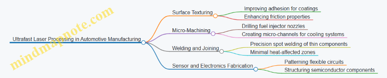
Surface Texturing for Improved Adhesion
One common use of ultrafast lasers is surface texturing to improve paint, adhesive, or coating adhesion on automotive parts. Traditional mechanical roughening can introduce contaminants or stress. Ultrafast lasers create micro- and nano-scale textures without significant heat buildup, preserving the base material’s properties.
Example: Laser texturing aluminum car body panels before painting enhances paint bonding. The laser pulses create uniform microgrooves that increase surface area and mechanical interlocking. This reduces paint peeling and improves corrosion resistance.
Best Practice: Optimize pulse energy and scanning speed to avoid melting or cracking. Use real-time monitoring to ensure consistent texture depth.
Micro-Machining of Fuel Injector Nozzles
Fuel injectors require extremely precise micro-holes to control fuel flow accurately. Ultrafast lasers can drill these holes with diameters in the tens of microns, maintaining sharp edges and minimal taper.
Example: A manufacturer uses femtosecond laser pulses to drill injector nozzles in stainless steel. The ultrafast pulses vaporize material with minimal heat diffusion, preventing deformation.
Best Practice: Employ multi-pass drilling with controlled overlap to achieve desired hole geometry. Use high-precision positioning stages to maintain alignment.
Welding and Joining Thin Components
Ultrafast lasers enable spot welding of thin metal sheets used in automotive frames and electronics. The short pulse duration confines heat to the weld zone, reducing distortion and residual stress.
Example: Welding aluminum battery casing components for electric vehicles. The laser creates strong welds without compromising battery integrity.
Best Practice: Adjust pulse duration and repetition rate to balance penetration depth and thermal load. Use shielding gas to prevent oxidation.
Sensor and Electronics Fabrication
Automotive sensors and flexible electronics benefit from ultrafast laser patterning. The lasers can ablate thin films or create microstructures on semiconductor substrates without damaging underlying layers.
Example: Patterning conductive traces on flexible polymer substrates for tire pressure sensors.
Best Practice: Calibrate laser fluence to selectively remove material without substrate damage. Integrate inline inspection to verify pattern fidelity.
Process Integration Mind Map
Summary
Ultrafast laser processing in automotive manufacturing addresses challenges where precision and minimal thermal impact are essential. From surface texturing to micro-machining and welding, the technology enables high-quality, repeatable results. Successful implementation depends on careful parameter optimization, integration with motion and monitoring systems, and adherence to best practices tailored to each application.
10.6 Lessons Learned and Best Practices from Industrial Deployments
Industrial use of ultrafast lasers has grown steadily, and with that growth comes a wealth of practical knowledge. This section summarizes key lessons and best practices gathered from real-world deployments, focusing on what works, what to avoid, and how to get the most consistent results.
Process Stability is King
Maintaining consistent laser parameters is crucial. Small fluctuations in pulse energy, repetition rate, or beam quality can cause significant variations in output quality. For example, a semiconductor manufacturer found that a 2% drop in pulse energy led to unacceptable defects in quantum dot arrays. Regular calibration and environmental controls (temperature, humidity) help keep parameters steady.
Material Preparation Matters
Surface cleanliness and preparation directly affect laser interaction. In aerospace micromachining, parts with residual oils or dust led to inconsistent ablation and surface roughness. Implementing standardized cleaning protocols before laser processing reduced defects by 15%. This is especially true for biofabrication, where contamination can compromise cell viability.
Optimize Before Automating
Automation is tempting but should come after process parameters are well understood. One electronics packaging line rushed into automating laser drilling before fully stabilizing the process, resulting in high rework rates. Taking time to map out optimal parameters and process windows first reduces costly adjustments later.
Real-Time Monitoring and Feedback Are Essential
Closed-loop control systems that adjust laser parameters on the fly improve yield and reduce scrap. For instance, a biofabrication facility used inline imaging to detect deviations in scaffold geometry, adjusting pulse energy in real time. This approach requires investment but pays off in consistency.
Understand Thermal Effects Even with Ultrafast Pulses
Despite ultrafast lasers minimizing heat-affected zones, some thermal accumulation can occur at high repetition rates. A polymer processing plant noticed microcracking when operating above certain pulse frequencies. Balancing speed and thermal load is key; sometimes slower is better.
Training and Cross-Disciplinary Teams Improve Outcomes
Operators with a mix of laser physics, materials science, and manufacturing knowledge produce better results. One biofabrication company found that pairing laser engineers with biologists shortened troubleshooting times and improved cell viability outcomes. Regular training and knowledge sharing are vital.
Documentation and Traceability Prevent Repetitive Errors
Keeping detailed records of laser parameters, material batches, and environmental conditions helps identify root causes when issues arise. A smart packaging line that implemented digital logs reduced downtime by quickly tracing faults back to specific parameter shifts.
Tailor Post-Processing to Laser Effects
Post-processing steps such as cleaning, annealing, or coating must consider laser-induced changes. For example, ultrafast laser texturing on metals sometimes leaves micro debris requiring ultrasonic cleaning to ensure adhesion of subsequent coatings.
Safety Protocols Should Match Laser Complexity
Ultrafast lasers often operate at high peak powers and can produce invisible radiation. Facilities that underestimated safety requirements faced near misses. Proper eyewear, interlocks, and training tailored to ultrafast laser hazards are non-negotiable.
Examples in Practice
-
Quantum Dot Fabrication: A manufacturer standardized laser pulse duration and energy, reducing size variability by 20%. They implemented inline photoluminescence monitoring to maintain quality.
-
Biofabrication Scaffold Production: By optimizing laser scanning speed and power, a tissue engineering firm improved scaffold porosity control, enhancing nutrient flow.
-
Microelectronics Packaging: A packaging line integrated real-time vision systems to detect misalignment during laser drilling, cutting defect rates in half.
In summary, successful industrial deployment of ultrafast lasers hinges on understanding and controlling the interplay between laser parameters, materials, environment, and human factors. Consistent monitoring, thorough preparation, and clear documentation form the backbone of reliable processes. These lessons, drawn from diverse applications, provide a solid foundation for anyone working with ultrafast laser technology in smart industry.