Personal Drone Utility Handbook
1. Safety Foundations for Consumer Drone Operations
1.1 Understanding Core Safety Responsibilities Before Flight
Before you lift off, safety isn’t a checklist you complete once. It’s a set of responsibilities you actively manage every time you fly, because drones combine moving parts, radio links, and real-world consequences. Your job is to prevent harm to people, property, and yourself, even when everything seems to be working.
What You Are Responsible For
You’re responsible for three categories of risk: the drone’s physical behavior, the information it collects, and the way you operate it.
- Physical behavior includes thrust, rotor wash, drop risk, and unexpected motion from wind or sensor errors. A drone that “should” hover can still drift when GPS reception is weak or when the wind changes.
- Information includes what your camera or sensors capture and how you handle it. Even if your intent is harmless, filming someone’s private area can create real problems.
- Operation includes your decisions: where you stand, how you approach obstacles, and whether you keep the drone within your ability to control it.
A practical way to think about it: if the drone did something boringly wrong—drift, lose stability, or land hard—would it still be unlikely to cause harm?
The Safety Mindset That Prevents Most Mistakes
Start with the assumption that conditions can change faster than you can react. Wind gusts, GPS multipath, and people walking into your space are common examples. Your responsibilities before flight are therefore about creating a buffer: space around the drone, clarity about what you’re doing, and a plan for what happens if things go sideways.
Use this simple rule: plan for the worst likely failure, not the rarest dramatic one. For example, “loss of link” is more common than “mysterious software apocalypse,” and it’s something you can prepare for.
Preflight Responsibility Workflow
A good preflight workflow turns safety into a sequence you can repeat.
- Confirm the environment: Identify people, pets, vehicles, and bystanders. If you can’t clearly see your surroundings, you’re not ready to fly.
- Confirm the airspace rules: Make sure you’re allowed to fly where you are and that you understand any local restrictions that apply to your exact location.
- Confirm the drone’s readiness: Check battery condition, propeller integrity, firmware status, and that sensors are behaving normally.
- Confirm your control plan: Decide where the drone will go if it drifts, and where you will stand so you can react quickly.
- Confirm your emergency plan: Know how you’ll respond to a flyaway, a sudden descent, or a loss of control.
If any step fails, you pause. Safety is not a “keep going and hope” activity.
Clear Boundaries for People and Property
Your safest boundary is the one that keeps the drone away from people and fragile items. That means you should not treat “it’s only a short flight” as a safety argument.
Consider a roof inspection near a driveway. Even if the drone is small, rotor wash can kick up dust, and a sudden drift can place the drone over a parked car or a person standing nearby. A responsible operator chooses a takeoff and landing area that doesn’t require stepping into the drone’s path.
A helpful example: if you’re filming eaves, position yourself so the drone’s initial climb is away from the sidewalk. That way, if something goes wrong in the first seconds, the likely outcome is still less harmful.
Privacy Responsibilities While You Fly
Privacy isn’t only about legality; it’s about minimizing unnecessary capture. Before flight, decide what you need to record and what you don’t.
- Frame so you avoid windows, backyards, and areas where people are likely to be identifiable.
- Keep the drone’s camera pointed at the task area, not at bystanders.
- If you must pass near private property, plan your route to reduce time spent capturing beyond what you need.
A practical example: when checking a fence line, fly a path that keeps the camera aimed at the fence and ground features rather than panning across neighboring yards.
Mind Map: Core Safety Responsibilities Before Flight
Example: A Safe First Flight for Roof Inspection
You arrive at a house for a quick roof check. You choose a takeoff spot in the yard with clear space in front of you and no people nearby. You verify the drone’s battery and propellers, then confirm the camera angle so it points at the roof area rather than the street. Before takeoff, you mentally rehearse what you’ll do if the drone drifts toward the driveway: you’ll move your stance to maintain control and avoid stepping into the drone’s path. You also set expectations for yourself—if wind picks up or you lose stable positioning, you stop and reassess.
That’s the core idea: safety responsibilities before flight are about reducing the chance that a normal mistake becomes a harmful event.
1.2 Preflight Checks for Airframe, Battery, Propellers, and Firmware
A good preflight is less about “hoping it works” and more about catching the small problems that turn into big ones. Use a consistent order so you don’t skip steps when you’re in a hurry.
Airframe Checks for Structural Integrity
Start with the frame because it’s the foundation for everything else.
- Look for cracks, dents, and loose parts. Check arms, landing gear, and the underside where drops and impacts usually show up. If a screw backs out once, it can back out again.
- Inspect mounts and covers. Make sure the camera mount is firmly seated and the gimbal cover (if used) is removed before flight. A slightly mis-seated mount can cause blurry footage and unstable control.
- Verify landing gear and prop guards. If you use guards, confirm they’re aligned and not rubbing the prop tips. Rubbing creates extra vibration and reduces control accuracy.
Example: After transporting the drone in a bag, do a quick “shake test” by gently holding the body and checking for rattles. If you hear movement near a motor or camera mount, stop and tighten or reseat before powering on.
Propeller Checks for Balance and Safety
Propellers are the most common failure point, and they also affect stability immediately.
- Confirm correct prop type and orientation. Many drones use different left/right props. Swapping them can prevent proper thrust and cause erratic behavior.
- Check for chips, bends, and wear. Even small nicks can unbalance the rotor. Replace props that show cracks at the blade root or along the leading edge.
- Ensure tight mounting. Props should be snug on the motor shaft. If your drone uses a locking mechanism, verify it clicks or locks fully.
- Check for debris. Remove tape, grass, dust, or dried mud from blade surfaces and motor housings.
Example: If you notice a prop blade looks slightly “whiter” at the tip than the others, that can indicate abrasion. Replace the set rather than mixing old and new blades.
Battery Checks for Capacity and Safe Power Delivery
Batteries can fail quietly until they fail loudly. Your job is to catch warning signs early.
- Inspect the battery casing. Look for swelling, punctures, frayed wires, or loose connectors. Any damage means “do not fly.”
- Confirm seating and connector condition. The battery should click firmly into place. If the connector feels loose or shows discoloration, clean gently and re-seat.
- Check charge level and temperature. Fly when the battery is within the manufacturer’s operating range. Cold batteries may sag under load; hot batteries may trigger protection.
- Review recent battery behavior. If the battery previously dropped from a higher percentage to a low percentage quickly, treat it as suspect and consider retiring it.
Example: If you charged the battery and it sat in a warm car, let it cool to room temperature before flight. A “full” battery that’s too hot can still behave like it’s half full.
Firmware Checks for Correct Behavior
Firmware issues often show up as odd sensor behavior, mismatched app settings, or unexpected prompts.
- Verify you’re on the expected firmware version. Use the app to confirm the drone and controller firmware match the intended setup.
- Update only when you can finish the process. If an update starts, don’t interrupt it mid-way. A half-updated system can lead to calibration prompts or degraded performance.
- Check for required post-update steps. Some updates require recalibration or gimbal checks. Follow the in-app prompts before your first flight.
- Confirm settings are consistent. Review camera mode, flight mode defaults, and safety options like return-to-home altitude.
Example: After a firmware update on 2026-03-05, do one short test hover in an open area. If the drone behaves normally, you can proceed to your planned task.
Mind Map: Preflight Workflow
A Practical Preflight Sequence You Can Memorize
- Airframe first: confirm nothing is loose or cracked.
- Props next: verify correct, undamaged, and clean blades.
- Battery last before power-up: inspect and seat properly.
- Firmware and settings: confirm version and safety defaults in the app.
Example: If you discover a prop chip after you already powered on, power down and replace. Starting a flight with a questionable prop is like starting a roof inspection with a missing flashlight—technically possible, practically unhelpful.
1.3 Risk Assessment for People, Property, and Bystander Safety
Risk assessment is the part where you decide, before takeoff, what could go wrong and what you will do about it. For consumer drones, the goal is not to eliminate risk entirely; it’s to keep the remaining risk at a level you can manage with clear actions.
Foundations for Thinking About Risk
Start with three buckets: people, property, and bystanders. “People” are you and your direct team. “Property” includes your own items and anything you’re responsible for during the flight. “Bystanders” are anyone else who might be affected even if they never look up.
Then use a simple equation: Risk = Likelihood × Severity. Likelihood asks how often a problem could happen in your specific situation. Severity asks what the worst realistic outcome would be if it did happen. A low-likelihood, high-severity event still deserves attention—especially when the “severity” involves injury.
Step 1: Identify Hazards in Your Specific Area
Walk the site like you’re inspecting it for obstacles and surprises. Common hazards include:
- People proximity: kids, pets, and people who may step into your flight path.
- Vertical obstacles: trees, poles, antennas, and roof edges that can clip rotors.
- Horizontal obstacles: fences, clotheslines, power cords, and parked vehicles.
- Surface hazards: gravel, wet grass, sand, and uneven ground that can cause unstable takeoff or landing.
- RF and signal issues: crowded areas, heavy interference, or weak line-of-sight.
- Environmental factors: wind gusts, rain, glare, and temperature effects on batteries.
A useful trick: imagine the drone drifting 10–20 feet in the wrong direction. If that drift would put it near people or fragile property, you need more distance or a different launch point.
Step 2: Estimate Likelihood and Severity
Likelihood changes with your choices. Flying closer to obstacles increases likelihood of contact. Flying in gusty wind increases likelihood of loss of control. Flying with a low battery increases likelihood of forced landings.
Severity depends on what the drone could hit and how fast it would be moving. A slow hover near a wall is less severe than a fast descent toward a person. A drone striking a parked car is different from striking a head-height area.
Use a practical severity scale:
- Low: minor damage to the drone, no realistic injury risk.
- Medium: likely property damage, injury unlikely but possible.
- High: plausible injury to a person or meaningful damage to critical property.
If you can’t confidently classify severity, assume it’s higher than you want. That conservatism is cheaper than repairs.
Step 3: Apply Controls That Reduce Risk
Controls come in layers. Prefer the earliest layer that solves the problem.
- Distance and positioning: Increase separation from bystanders and fragile property. Choose a launch spot that keeps the drone’s “out-of-control” drift away from people.
- Speed and altitude discipline: Keep movements smooth and avoid aggressive maneuvers near obstacles. Higher altitude can help clearance, but it can also reduce your ability to react quickly if something goes wrong.
- Operational limits: Set conservative maximum distances and altitudes in your app if available. Plan your flight so you can land with margin.
- People management: Assign a spotter when you’re operating near others. The spotter’s job is to watch the drone’s path and the crowd, not to chat.
- Preplanned abort actions: Decide in advance what “stop” means. For example: if wind increases, you land immediately rather than “finishing one more pass.”
Step 4: Confirm Readiness Before Takeoff
A readiness check prevents the classic mistake: assessing risk in theory, then launching with a different reality.
Confirm:
- You have a clear landing zone with no loose debris.
- You can maintain line-of-sight to the drone.
- You’ve checked battery level and expected flight time.
- You’ve verified the controller link and GPS status.
- You know where you will land if you lose the planned route.
Mind Map: Risk Assessment
Example: Roof Inspection Near a Driveway
You plan a low pass to capture roof flashing details. The driveway has two cars parked and a neighbor’s child playing near the gate.
- Hazards: bystander proximity, vehicle as fragile property, and a fence line that could force a drift into the yard.
- Likelihood: medium, because you’ll fly low and close to obstacles.
- Severity: high if the drone drifts into head-height space.
Controls: You move the launch point farther from the gate, extend the buffer zone, and ask a spotter to keep the child behind the line. You also set a conservative maximum altitude and plan a direct landing if wind increases. The result is a flight that still captures the needed angles, but with fewer “oops” opportunities.
Example: Thermal Check in Light Wind
You’re doing a short thermal sweep at night. The yard is open, but there’s a walkway where neighbors might pass.
- Hazards: bystander movement and reduced visibility.
- Likelihood: low-to-medium, because the area is open but people could enter the walkway.
- Severity: medium, since the drone is moving slowly and you can keep it higher than head level.
Controls: You choose a time when foot traffic is unlikely, keep the drone’s path away from the walkway, and maintain a clear abort plan. You also avoid hovering directly above the walkway even if the camera view is tempting.
Quick Preflight Decision Rule
If you can’t explain, in one sentence, how you will keep the drone away from people and fragile property if something goes wrong, you’re not ready to fly yet.
1.4 Safe Takeoff Landing and Ground Handling Practices
Safe takeoff and landing are less about heroics and more about repeatable habits. The goal is simple: keep the drone predictable, keep people and property protected, and keep your own attention where it matters—on the aircraft.
Ground Handling Before You Lift Off
Start with a “hands-on” routine that prevents surprises. Place the drone on level ground, away from loose gravel, tall grass, and anything that can snag a propeller. If you’re on a driveway or patio, do a quick sweep for small stones and debris; one pebble can become a propeller wobble.
Use a consistent orientation marker. For example, pick a visual cue on the drone body (like a front arm or landing leg) and always treat that as the “front.” When you move the drone by hand, keep props clear and avoid spinning them. If the drone has a gimbal camera, keep it from swinging into the ground by ensuring the drone is stable before powering on.
Pre-Takeoff Checks That Actually Affect Safety
Before takeoff, confirm three categories: aircraft readiness, environment, and your control setup.
-
Aircraft readiness: verify battery level, propeller condition, and that the drone reports normal status. If you see warnings about sensors or compass, don’t treat them as “minor.” Fix the cause first.
-
Environment: check wind at ground level by watching nearby leaves or light flags. If the drone is already being pushed around while stationary, it will be worse in the air.
-
Control setup: ensure the return-to-home setting is sensible for your location and that you can see the drone’s orientation clearly on the screen.
A practical example: if you’re inspecting a roof edge, stand so the drone’s front stays oriented toward you. That makes it easier to interpret left-right inputs during the first seconds of flight.
Takeoff Technique for Predictable Control
Takeoff is where many incidents begin because the drone is transitioning from “still” to “responsive.” Use a slow, deliberate lift. Apply gentle throttle until the drone becomes fully airborne, then pause briefly to confirm stability.
Keep your first movement small. Instead of immediately flying forward, rise to a safe hover height and confirm that:
- The drone holds position without drifting rapidly.
- The camera view matches the drone’s orientation.
- You can stop and hover again without overshooting.
If the drone drifts, land and reassess. Common causes include wind, uneven ground, or sensor calibration issues. Don’t try to “fight” drift with aggressive control inputs; that often makes the drone harder to stabilize.
Managing People, Pets, and Obstacles
Treat people and pets as moving obstacles with unpredictable paths. Establish a “no-walk zone” around your takeoff and landing spot. If you’re working near a yard, ask someone to stay behind you, not beside you, so you can keep the drone’s front orientation consistent.
For pets, the safest approach is simple: don’t launch while they’re actively curious. Wait until they’re inside or securely restrained. A dog that runs toward the drone can cause a sudden stop, a prop strike, or a panic grab.
Obstacles deserve different handling than people. For example, trees and power lines require lateral clearance, but they also affect wind turbulence. If you must operate near structures, increase your hover height and keep your first forward movement away from the most turbulent side.
Landing Technique That Prevents Damage
Landing should be as controlled as takeoff. Begin by slowing your descent early. If you wait too long and then drop quickly, you increase the chance of a hard landing or prop wash disturbance.
Choose a landing spot that is clean and level. If you’re landing on grass, avoid thick patches that can catch landing legs or create uneven contact. If you’re landing on a surface with dust or sand, expect more debris around the props and plan to land with extra care.
A helpful habit: land with a slight hover pause just above the ground. Confirm the drone is centered over the landing area, then lower gently.
Using Return-to-Home and Auto-Landing Carefully
Return-to-home and auto-landing can be useful, but they’re not a substitute for good setup. Before relying on them, verify that the drone’s programmed altitude clears nearby obstacles. If the route back would cross trees, buildings, or power lines, you should not treat return-to-home as “safe by default.”
For auto-landing, ensure the landing area remains clear. If someone walks into the landing zone while the drone is descending, the safest action is to intervene according to your drone’s control options and safety guidance.
Mind Map: Safe Takeoff Landing and Ground Handling
Example: Roof Inspection Launch and Recovery
You’re about to inspect a roof edge from the driveway. You place the drone on a clear patch of concrete, confirm the front orientation marker, and power on. You check wind by watching a nearby plant and verify the drone reports normal status. You lift slowly to a hover height that clears the roofline, pause to confirm stable position, then move laterally toward the inspection area.
When finished, you return to the original landing spot. You descend early, hover briefly to confirm centering, and lower gently. If you notice drift during the approach, you stop the descent, re-center, and only then continue. This keeps the landing predictable even when the wind is doing its own thing.
1.5 Emergency Procedures for Flyaway, Loss of Link, and Crash Response
Emergencies usually start as small surprises: a sudden drift, a controller warning, or a brief video freeze. The goal is to reduce decision time and keep actions consistent, so you don’t have to “think hard” while your drone is doing something unexpected.
Build a Default Decision Ladder
When something goes wrong, your brain wants to improvise. Instead, use a simple ladder:
- Stabilize first: keep the drone’s attitude under control and avoid aggressive stick inputs.
- Stop the escalation: reduce speed and stop moving toward hazards.
- Use the drone’s safety mode: let built-in behaviors handle the next step.
- Recover or secure: regain control if possible, otherwise prioritize people and property.
A good habit is to rehearse this ladder on the ground with the controller powered on, so the steps feel familiar.
Flyaway Procedures That Minimize Damage
A flyaway is often caused by GPS issues, compass interference, or a control signal problem. Treat it as a control-and-position problem, not a “panic problem.”
Immediate actions
- Release aggressive inputs: center sticks to stop unintended commands.
- Check orientation: confirm which way the drone is facing so you don’t fight the wrong direction.
- Switch to Return to Home if available: if the drone has a reliable home point and the app shows it, initiate Return to Home.
- If Return to Home is unsafe: for example, it would cross through a window or power line, cancel it and attempt a controlled landing.
Example: You’re inspecting a roof edge and the drone begins drifting sideways over a driveway. You center the sticks, confirm the drone’s heading on the screen, and trigger Return to Home. If the path would pass near a parked car, you cancel Return to Home and command a gentle descent while maintaining a safe lateral position.
Advanced detail that matters
- If the drone is already moving away, trying to “pull it back” with full stick deflection can worsen the situation by creating oscillations.
- If the app shows poor GPS quality, expect Return to Home to be less precise. In that case, prioritize a controlled landing over a perfect return.
Loss of Link Procedures That Reduce Uncertainty
Loss of link means you can’t reliably command the drone. The best move depends on what the drone is set to do when the signal drops.
Before you fly
- Confirm the Failsafe behavior in your app settings: typical options include hover, Return to Home, or land.
- Verify the Return to Home altitude is high enough to clear obstacles, but not so high that it risks ceiling-level hazards.
During loss of link
- Do not chase: walking quickly after the drone can put you in the flight path and doesn’t restore control.
- Watch the drone’s behavior: if it is climbing to Return to Home, keep people clear and stand to the side.
- If it is descending or landing: keep your distance and be ready to move away from the landing zone.
Example: While flying near tall trees, the video feed freezes and the controller warns of link loss. The drone begins a programmed Return to Home climb. You stop moving, keep bystanders behind you, and wait for the drone to reach the planned altitude before it turns back.
If you regain link
- Resume control smoothly. Avoid sudden reversals; the drone may have drifted during the outage.
- If the drone is near an obstacle, prioritize a stable hover or immediate landing rather than continuing the original task.
Crash Response That Protects People and Preserves Evidence
A crash can be minor (prop strike, hard landing) or severe (battery damage, fire risk). Treat it as a safety event first.
Immediate actions
- Approach carefully: if the drone is still powered, keep your hands away from the prop area.
- Turn off power if safe: power down the controller, then the drone if you can do so without reaching into danger.
- Check for heat or smoke: if you see swelling, hissing, or smoke, keep distance and wait.
After the scene is safe
- Inspect the battery: do not puncture or squeeze it.
- Document what you can: note the time, location, weather, and what the drone was doing right before impact.
- Inspect props and motors: bent props are often the first visible cause, but motor damage can also be present.
Example: The drone clips a gutter and drops. You keep your distance, power down, and check the battery for heat. After confirming it’s safe, you photograph the damage, note the wind at the time, and replace the prop before testing again.
Mind Map for Emergency Actions
Emergency Procedures Mind Map
Practical Preflight Checks That Prevent Most Emergencies
Most “emergencies” are preventable with two minutes of setup: verify failsafe behavior, confirm Return to Home altitude, and ensure home point is correct. Then, during flight, keep a clear line of sight to the drone’s general position so you can react early instead of late.
2. Legal and Administrative Requirements for Everyday Use
2.1 Determining Where You Can Fly Based on Location and Airspace
Before you power on the drone, you need a simple answer to one question: “Is this location allowed for the kind of flight I’m planning?” The trick is that “allowed” depends on both where you are and what airspace rules apply there, which can change by country, region, and even specific zones.
Start with Your Location Facts
Begin by collecting the basics you can verify on the ground.
- Exact takeoff point: Use a map pin or note the address and nearest cross street.
- Planned flight area: Roof edge, yard perimeter, or a corridor along a fence line.
- Altitude you intend to use: Many restrictions are altitude-based, so guesswork is risky.
- Time of operation: Some areas restrict flights during events or at certain hours.
Example: You want to inspect a roof. You take off from the driveway, but the drone’s camera path might extend over the neighbor’s yard. Your “location” is not just your driveway; it’s the whole area your flight will cover.
Understand Airspace Categories in Plain Language
Airspace is usually organized into layers with different rules. You don’t need to memorize every category name, but you should recognize the common patterns.
- Controlled airspace: Often requires authorization or communication with air traffic services.
- Restricted or prohibited areas: Entry may be forbidden or tightly limited.
- Temporary flight restrictions: Short-term limits can appear for emergencies, events, or operations.
- Uncontrolled or general areas: Rules still apply, but they’re typically less complex.
A useful mental model: if the airspace is “managed,” you may need permission; if it’s “restricted,” you may need to avoid it entirely.
Check for Local Restrictions That Override “General Rules”
Even if your general area seems fine, local overlays can change the outcome.
- No-fly zones near airports and heliports: These are often the most common hard stops.
- Military or sensitive facilities: Some areas are restricted regardless of altitude.
- Crowd and event zones: Restrictions may apply even when the airspace itself is otherwise normal.
- Government buildings and critical infrastructure: Rules can be stricter than you’d expect.
Example: Your neighborhood is outside an airport boundary, so you assume it’s okay. Then you notice a stadium event zone covering the same direction you plan to fly. The drone might be legal in one direction and not the other.
Use a Stepwise Verification Workflow
Treat airspace checking like a checklist, not a vibe.
- Locate your takeoff point on a map.
- Mark your intended flight footprint (where the drone will go).
- Identify the airspace type covering that footprint.
- Confirm altitude limits for your specific operation.
- Look for temporary restrictions active at your planned time.
- Verify operational permissions if required (authorization, remote ID rules, or communication requirements).
- Recheck before takeoff in case conditions changed.
Example: You plan a thermal check at dusk. You verify the airspace at 5:30, but you start the flight at 6:10. If a temporary restriction begins at 6:00, your earlier check is no longer enough.
Translate Airspace Rules into Practical Flight Boundaries
Once you know what’s allowed, convert it into boundaries you can actually fly.
- Define a “safe box”: A polygon or rectangle that stays within permitted airspace.
- Set altitude ceilings: Use a hard cap in the drone app if available.
- Plan return paths: Ensure your route back to the takeoff point remains inside the allowed area.
- Avoid “just in case” drift: Wind and GPS error can push the drone beyond your intended boundary.
Example: For a perimeter patrol, you set a route along the property line. If the permitted area ends 20 meters short of the line, you shorten the route and keep a buffer so the drone doesn’t drift into the edge case.
Mind Map: Where You Can Fly
Where You Can Fly Mind Map
Common Mistakes and How to Avoid Them
- Checking only the takeoff point: The drone’s path matters.
- Assuming altitude alone determines legality: Some zones restrict regardless of height.
- Ignoring temporary restrictions: They can start and end quickly.
- Not planning for drift: A “legal” route can become illegal if the drone wanders.
Example: You fly straight out for a roof photo. The return path is slightly different due to wind, and the drone crosses into a nearby restricted corridor. The fix is to plan both outbound and inbound routes within the permitted footprint.
Quick Self-Test Before You Launch
If you can answer these in one minute, you’re ready to proceed.
- Where exactly am I taking off?
- What area will the drone actually cover?
- What altitude ceiling am I using?
- Are there temporary restrictions at my planned time?
- Does my return path stay inside the allowed area?
When those answers are clear, you’ve done the boring part correctly—the part that keeps the rest of the operation straightforward.
2.2 Understanding Remote Pilot Requirements and Training Options
Remote pilot requirements are mostly about two things: proving you understand safe operation, and ensuring you can follow rules even when the drone is behaving like a stubborn shopping cart. The exact steps depend on your country and sometimes your specific drone weight and use case, but the logic stays consistent.
Foundational Concepts You Must Know First
Start by separating three roles that often get mixed up:
- Remote pilot: the person who actually controls the aircraft during flight.
- Operator: the person who has overall responsibility for how the flight is conducted.
- Observer: a spotter who helps with visual scanning and situational awareness.
In many everyday scenarios, one person fills multiple roles, but the responsibilities still exist. If you’re the one flying, you’re typically the remote pilot.
Next, understand that requirements usually hinge on:
- Where you fly (airspace class, controlled vs. uncontrolled areas, and local restrictions).
- What you do (recreational vs. commercial-like activities, and whether you’re collecting data for compensation).
- How you fly (line of sight vs. beyond visual line of sight, altitude limits, and proximity to people).
- What you fly (aircraft weight category and whether it’s considered a “toy” or an aircraft for regulatory purposes).
A practical way to keep this straight is to treat each flight as a checklist item: location, purpose, flight mode, and aircraft category.
Training Options and What They Actually Cover
Training options generally fall into three buckets. You can choose based on your comfort level and how often you plan to fly.
Option 1: Self-Study with Exam
This is common when you already understand basic aviation concepts and want a structured path to a test. The training typically covers:
- Airspace awareness and common restriction types.
- Weather basics that affect control and visibility.
- Risk management around people, property, and emergency scenarios.
- Operational procedures like preflight checks and lost-link behavior.
Example: You plan roof inspections on weekends. You study airspace rules, practice interpreting restriction zones, and take the exam. On flight day, you can explain why you chose a particular takeoff point and how you’ll stop if wind pushes you toward a neighbor’s yard.
Option 2: Instructor-Led Course
Instructor-led training helps when you want guided practice and feedback. It often includes scenario walkthroughs and sometimes simulator-style exercises.
What you gain is not just knowledge, but the ability to apply it under time pressure. You learn to:
- Identify hazards quickly.
- Decide when to delay or cancel.
- Communicate roles if you have an observer.
Example: You’re new to drones and frequently fly near your property line. In class, you practice scanning patterns and learn a simple rule: if you can’t maintain clear visual contact with the aircraft and its flight path, you don’t continue.
Option 3: Practical Training with Supervised Flights
Some programs include supervised flight sessions. This is where you confirm that your “I think I can” becomes “I can.” You typically practice:
- Smooth takeoff and landing.
- Stable hover and controlled movement.
- Emergency procedures like returning to home and handling abnormal behavior.
Example: During supervised practice, you discover that your first attempt at a consistent inspection altitude is too high or too low. You adjust your workflow so the camera captures usable detail without forcing risky maneuvers.
How Requirements Map to Real Flights
Use a simple decision flow before you even think about cameras or thermal settings.
Mind Map: Remote Pilot Requirements Workflow
Common Gaps That Cause Trouble
Even careful people miss predictable details. The most frequent gaps are:
- Assuming the same rules apply everywhere. Requirements can change by country and sometimes by region.
- Confusing “I’m just doing it for myself” with “it’s automatically exempt.” Purpose matters.
- Treating training as a one-time event. You still need to follow procedures every flight, not just on exam day.
- Ignoring observer and visual scanning practices. A drone can be small and fast, and your eyes are not a tracking system.
Example: You hold a remote pilot credential but plan a flight in a restricted area because you relied on a familiar route. The credential doesn’t override airspace restrictions; it just means you know how to comply.
A Practical Readiness Checklist
Before choosing training, confirm you can answer these questions:
- What is your country’s remote pilot requirement for your drone category?
- Does your intended use count as recreational or work-like activity?
- Do you plan to fly near people or over property boundaries?
- Will you need an observer, and do you understand their role?
- Are you comfortable with emergency procedures like return-to-home and landing safely?
If you can’t answer one of these, that’s not a failure. It’s a sign you should pick a training option that fills the specific gap—because the goal is not passing paperwork, it’s flying in a way that stays within the rules.
2.3 Managing Registration, Marking, and Documentation
Consumer drones are usually simple to fly, but the paperwork side is where people get tripped up. This section explains what to register, what to mark, and what to document so you can prove what you did and fly again without guesswork.
Registration Essentials for Personal UAV Use
Registration is the step that ties you to the aircraft in the eyes of the regulator. In practice, you’ll create an account, provide your details, and link the drone to that account. Many systems issue a unique identifier that must be displayed on the aircraft.
A practical approach is to register before your first “real” job. For example, if you plan to inspect a roof on Saturday, register the drone on Wednesday and print or apply the identifier by Thursday. That way, you’re not trying to solve admin problems while the battery is already charged.
Keep a short checklist:
- Confirm the drone model and serial number match what you registered.
- Save your registration confirmation and identifier details.
- Verify whether the identifier must be on the outside of the drone or can be stored digitally.
Marking Requirements and How to Do Them Cleanly
Marking is the physical or electronic display of the identifier. If your drone requires a visible mark, apply it where it won’t be damaged by prop wash, cleaning, or minor scrapes. A common mistake is placing the label on a curved surface where it peels after a few flights.
Use a label strategy that survives real life:
- Choose a location with flat surface area.
- Use durable adhesive and avoid covering vents or sensors.
- Ensure the identifier is readable without removing parts.
Example: You buy a new drone, register it, and receive an identifier. You apply a small label on the underside arm where it won’t interfere with landing. After the first week, you check it in good light and confirm it still reads correctly.
Documentation That Actually Helps During Real Work
Documentation is more than “keeping receipts.” It’s a record that supports safe operation, troubleshooting, and compliance. Build a folder structure that mirrors your tasks: one for registration, one for flight logs, and one for maintenance.
Include these items:
- Registration confirmation and identifier details.
- Proof of remote pilot training or eligibility, if applicable.
- A basic flight log: date, location, drone used, purpose, and any incidents.
- Maintenance notes: battery replacements, firmware updates, and repairs.
A simple flight log template prevents vague memories. For roof inspections, add what you were checking. For example: “Captured eave close-ups; suspected flashing gap; repeated pass after wind gust.” That single sentence tells you why you flew again.
Integrated Workflow from Setup to Evidence
Treat the process like a loop: register once, mark correctly, then document each flight so you can reconstruct what happened.
- Register the drone and save confirmation.
- Apply the identifier mark and verify readability.
- Before each session, confirm the drone matches the identifier.
- During the flight, record the purpose and any anomalies.
- After the flight, store media and update the log.
If you ever need to explain your actions, your documentation should answer three questions quickly: what drone, who operated it, and what you were doing.
Mind Map: Registration, Marking, and Documentation
Example: Roof Inspection Admin Done Before Flight
On May 1, you register a drone and save the confirmation email. On May 2, you apply the identifier label to the underside arm and verify it reads clearly in daylight. On May 3, you run a short preflight check and confirm the drone you’re using is the one you registered.
During the inspection, you note the purpose in your log: “Check flashing around chimney; capture overlapping close-ups.” After a gust causes slight blur, you record “Second pass at lower speed” and then store the new media in the roof folder. When you review later, your notes tell you why there are two sets of images and which one to use for the final report.
Example: Handling a Marking Issue Without Panic
If the label starts peeling, don’t keep flying “until it’s fixed.” Stop, replace the mark, and update your documentation with the date of the correction. In your flight log, add a brief note such as “Identifier mark reapplied; no flights between correction and verification.” That keeps your record consistent and avoids confusion later.
2.4 Privacy and Data Handling for Cameras and Sensors
Privacy isn’t just about whether you can fly; it’s about what your drone records, how long you keep it, and who can access it afterward. Consumer UAVs often capture more than you intend: wide establishing shots, audio from video clips, and location metadata embedded in files. Treat every flight like it will be reviewed later by someone who wasn’t there.
What Your Drone Actually Collects
Start with a simple inventory of data types:
- Visual data: Photos and video from the camera and gimbal.
- Thermal data: Temperature imagery that can reveal patterns even when visible light is unhelpful.
- Location data: Many apps embed GPS coordinates in media files.
- Operational logs: Flight records, route traces, and sometimes device identifiers.
- Audio: Some drones record sound with video.
A practical example: you film your roof edge to check flashing, but the camera’s wide view also captures a neighbor’s driveway and a parked car. Even if you never “mean” to record them, the file still contains it.
Privacy by Design Before You Lift Off
Privacy-friendly habits begin before takeoff:
- Choose framing intentionally. Use the live camera view to confirm what enters the frame. If a window or yard is visible, adjust your route or altitude.
- Plan for cropping. If you know you’ll need close detail, fly closer rather than wide. That reduces the amount of unrelated background you must later manage.
- Limit unnecessary recording. If your task is a short inspection, avoid long hover footage that captures more than needed.
- Use privacy-respecting settings. Turn off features you don’t need, such as unnecessary overlays or any option that stores extra data you won’t use.
A quick rule: if you wouldn’t want the same footage shared publicly, don’t capture it casually.
Data Minimization and Retention
Data minimization means keeping only what you need for the task. Retention means deciding how long you keep it.
- Keep task-critical files: the specific images that show the issue, the measurement reference, or the thermal anomaly.
- Delete or archive the rest: wide shots that include neighbors, repeated takes, and test footage.
- Set a review window: for example, review the day’s media the same evening, then delete the obvious “not useful” clips.
Example workflow for roof inspection: after the flight, you select 20 close-up photos of vents and flashing. You delete the 3-minute establishing video that includes the street and adjacent property. You keep the selected photos in a folder labeled with the inspection date, then remove the rest from the device.
Access Control and Sharing Boundaries
Your privacy risk increases when files leave your control. Keep these boundaries clear:
- Use device locks on the controller and phone/tablet.
- Restrict shared accounts. If multiple people use the same phone, separate photo libraries or user profiles.
- Share only what’s needed. When sending images to a contractor, export cropped versions that exclude unrelated areas.
- Avoid forwarding raw files when a trimmed export works.
Example: you email thermal images to a technician. Instead of sending the original file with embedded GPS, export a version without location metadata and crop to the roof section only.
Metadata and Location Awareness
Location metadata can be helpful for your own organization, but it can expose more than you expect. Many media files can include GPS coordinates and timestamps.
- For personal records, keep metadata if it helps you match findings to a specific place.
- For sharing, consider removing location data and cropping to the relevant area.
A concrete check: open a photo’s details on your phone. If it shows a map pin for your home, assume the same pin will travel with the file unless you remove it.
Mind Map: Privacy and Data Handling Flow
Example: Privacy-Safe Thermal Check
You suspect a heat-loss issue near a basement window. You fly at an angle that keeps the camera pointed at your exterior wall and avoids the neighbor’s yard. After landing, you review the thermal clips and select only the frames showing the window area. You crop out any adjacent property and export a shareable image without location details. Finally, you delete the original wide thermal clip from the device storage.
Example: Evidence Without Over-Collection
For security patrol, you want to confirm whether a gate was left open. You record short passes rather than long loops, and you avoid capturing faces or license plates when possible by keeping the camera oriented toward the gate area. If you need evidence, you export a clip trimmed to the relevant time window and share it only with household members who need it.
Practical Checklist for Privacy-Respectful Handling
- Confirm what appears in the frame before takeoff.
- Capture close, task-relevant angles.
- Review media the same day and delete what you don’t need.
- Crop before sharing.
- Remove location metadata when sending files outside your household.
- Lock devices and limit who can access your media library.
Privacy handling is mostly boring work: careful framing, quick review, and disciplined file management. That’s the point—your drone should be useful without turning your neighborhood into an accidental archive.
2.5 Operating Near People, Vehicles, and Private Property Boundaries
Operating near people and vehicles is where “it should be fine” stops being a useful plan. The goal is simple: prevent contact, prevent surprise, and keep your drone’s behavior predictable. This section turns that goal into practical steps you can repeat.
Core Principle: Predictable Motion Beats Perfect Control
A consumer drone can be precise in calm conditions, but it is not a magic wand. Treat every flight near people or property lines as if someone might step into your path, a door might open, or a vehicle might roll forward. Your job is to set up the flight so the drone can’t easily cause harm even when the world changes.
People: Build a Buffer and a Communication Habit
Start with a physical buffer. If you can’t maintain a clear distance where the drone would not reach a person if it drifted, don’t fly. Use a “stand-off” mindset: you should be able to abort immediately and still keep the drone away from anyone on the ground.
Before takeoff, do a quick ground check: identify where people are likely to move—walkways, driveways, gates, and the side of the house where someone might come out with a trash bin. Then choose a flight pattern that keeps the drone’s path away from those zones.
A simple communication habit helps: tell people what you’re doing and what you need from them. For example, “I’m going to hover for a minute near the driveway; please stay behind the porch line.” This reduces sudden movement and makes it easier to pause without confusion.
Vehicles: Treat Doors, Wheels, and Wind as Moving Targets
Vehicles add two hazards: sudden motion and airflow. A car door can open without warning, and wind turbulence near a vehicle can push the drone off its intended line.
Practical setup:
- Keep the drone high enough that it won’t be affected by door-level turbulence, but not so high that you lose visual confirmation.
- Avoid flying directly over vehicles. If you must capture an angle, approach from the side and keep the drone’s travel path outside the vehicle’s immediate space.
- Plan for the driver’s actions. If someone is in the vehicle, assume they may start moving or exit.
Example: You want to inspect a roof edge above a parked car. Instead of flying straight over the car, fly a parallel line from the driveway side, then rotate the camera downward while maintaining lateral distance. If the car shifts or a person approaches, you can back out without crossing over the vehicle.
Private Property Boundaries: Respect the Line and the Context
A boundary is not just a legal concept; it’s also a practical one. Even if you can technically see over a fence, you should assume you might capture images of areas you don’t intend to document.
Use three layers of boundary thinking:
- Physical boundary: keep the drone’s flight path inside your intended area.
- Visual boundary: avoid framing that includes neighboring yards, windows, or private entrances.
- Operational boundary: plan your route so you can stop and retreat without drifting toward the line.
Mind the “edge effect.” GPS drift, wind gusts, and control inputs can nudge the drone toward the boundary. The fix is not complicated: increase your buffer distance near fences and gates, and avoid hovering right at the edge of your comfort zone.
Risk Controls: Altitude, Speed, and Abort Readiness
Near people and boundaries, your settings should reduce surprises.
- Altitude control: fly at an altitude where you can maintain clear visual contact and where a sudden correction won’t swing the drone toward people.
- Speed control: use slower movement when transitioning between positions. Fast lateral moves near boundaries are where “oops” happens.
- Abort readiness: know your immediate landing or retreat point before you take off. If you lose situational awareness, you should be able to stop the mission quickly.
Mind Map: Operating Near People, Vehicles, and Boundaries
Example: Roof Inspection Without Crossing the Line
You’re inspecting a gutter section near a shared driveway. You plan a route that stays on your side of the boundary and keeps the camera pointed down at the target area. You start with a short hover to confirm framing, then move laterally in small increments while watching for wind drift. If a neighbor steps outside, you pause, raise slightly if needed to maintain clearance, and retreat to your preplanned landing point. The photos you capture focus on the roof surface, not the neighbor’s yard or windows.
Example: Thermal Check Near a Patio
Thermal imaging can reveal more than you expect because it shows heat patterns across surfaces. Before flying, you decide which surfaces you will capture and which you will avoid. You keep the drone’s position far enough from the patio that it cannot drift into the seating area, and you avoid camera angles that include private doors or windows. If someone appears in the frame, you stop and recompose from a safer position rather than continuing.
Quick Checklist Before You Fly
- Buffer distance is large enough for drift and immediate retreat.
- Flight path avoids walkways, gates, and vehicle space.
- Camera framing avoids neighboring private areas.
- You can pause, back out, and land without crossing the boundary.
- You’ve communicated your intent to anyone nearby.
3. Choosing a Consumer UAV for Utility Work
3.1 Matching Drone Features to Roof Inspection and Survey Needs
A roof inspection drone is only as useful as the features that match the job. Start by separating “what you need to see” from “how you need to measure,” then map those needs to camera, flight, and workflow capabilities. If you skip that step, you end up with great footage of the wrong details—or measurements that look precise but aren’t repeatable.
Foundational Requirements for Roof Work
Roof inspection usually has two goals: visual documentation and defect triage. Visual documentation means capturing clear, consistent images of edges, penetrations, and transitions. Defect triage means spotting patterns like missing shingles, lifted flashing, clogged gutters, or water staining.
Survey work adds a third goal: measurement consistency. You may not need survey-grade accuracy, but you do need repeatable geometry—consistent overlap, stable camera settings, and a way to reference locations.
A practical way to decide is to ask three questions before you buy or configure anything:
- Detail: Can the camera resolve small features at the distances you’ll fly?
- Coverage: Can you capture the whole area without constant repositioning?
- Consistency: Can you reproduce the same view later for “before and after” comparisons?
Camera Features That Actually Matter
Resolution and Lens Behavior
Higher resolution helps, but it doesn’t fix poor distance or glare. For roof work, prioritize a camera that can focus reliably at the distances you’ll use. If your drone supports multiple camera modes, choose the one that keeps exposure stable across the flight.
A common mistake is flying too high “to get everything,” then discovering that ridge details and flashing edges become soft. For close inspection, you want a camera that stays sharp when you approach and when you tilt the gimbal.
Gimbal Control and Angle Discipline
A 3-axis gimbal keeps images steady, but your technique matters more than people expect. For roof inspection, you’ll often need oblique angles to see under eaves and around vents. The feature to look for is smooth gimbal control with predictable tilt limits, so you can frame edges without sudden jumps.
Example: If you’re checking a chimney base, aim for a consistent angle across multiple passes. If the gimbal snaps between angles, you’ll lose the ability to compare images later.
Exposure and White Balance Stability
Auto exposure can change brightness between frames, which makes it harder to compare staining or material differences. Look for settings that let you lock exposure or at least reduce variability. If your drone offers manual control, use it for inspection flights.
Example: When photographing water staining on a north-facing slope, keep exposure consistent so the “darker” areas remain darker across the set.
Flight and Imaging Features for Coverage
Waypoints and Pattern Coverage
Roof geometry is repetitive: ridges, valleys, and repeating shingle lines. Pattern coverage helps you avoid gaps. If your drone supports waypoint flights or grid-like coverage, it can reduce missed areas.
However, automated paths can still fail if you don’t set altitude and overlap correctly. Use the feature for consistency, not for thinking on your behalf.
Speed, Wind Handling, and Stability
Slow, stable flight improves image sharpness and overlap quality. Wind tolerance matters because roof edges create turbulence. A drone that holds position well lets you keep the camera angle steady while you work along eaves and corners.
Example: On a breezy day, you may need to reduce speed and increase your buffer from the roof edge. The “best” drone is the one that stays controllable when you’re close to the structure.
Obstacle Sensing and Its Limits
Obstacle sensing can prevent collisions, but it can also distract you with unexpected braking near textured surfaces like shingles. Treat obstacle sensing as a safety net, not a planning tool. Plan your path with margins, then let sensing help when you misjudge.
Survey-Relevant Features for Measurement
Overlap Capability and Repeatability
For photogrammetry-style survey outputs, overlap is the difference between “a model” and “a pile of blurry guesses.” The key features are camera stability, predictable flight paths, and the ability to maintain consistent altitude.
If you can’t reliably repeat the same flight parameters, your survey comparisons will be unreliable.
Example: If you’re measuring a roof after repairs, record the same flight altitude, gimbal angle range, and path style. Even without perfect survey accuracy, consistent capture makes comparisons meaningful.
File Management and Metadata
Survey and inspection both benefit from organized media. Look for workflows that preserve original files and keep timestamps and location data intact. If your app compresses or renames files unpredictably, you’ll spend time untangling sets instead of reviewing details.
Mind Map: Matching Features to Roof Tasks
Example: Choosing Features for Three Common Roof Tasks
Task 1: Shingle Condition Check
Prioritize sharp close detail, stable gimbal tilt, and exposure consistency. A drone that holds position well lets you hover near ridge lines without turning the image into a motion blur festival.
Task 2: Flashing and Penetration Inspection
Prioritize smooth oblique angles and predictable framing. You’ll often need to see around corners and under edges, so gimbal control and stable flight matter more than raw resolution.
Task 3: Roof Area Measurement for Repair Planning
Prioritize repeatable flight paths, consistent altitude, and overlap-friendly capture. Also prioritize file organization so you can match the “before” set to the “after” set without guessing.
When you match features to the actual job—detail, coverage, and repeatability—you get images you can trust and measurements you can explain. That’s the whole trick: the drone isn’t the hero; it’s the tool that behaves predictably while you do the thinking.
3.2 Camera and Gimbal Requirements for Close Range Detail
Close-range roof and property work is mostly about getting the right pixels on the right surfaces, with minimal distortion and repeatable framing. A consumer drone camera can do this well, but only if you match the camera and gimbal behavior to the task.
What Close Range Detail Actually Requires
Start with three constraints: distance, angle, and stability. At close range, small changes in distance can shift focus and scale, while angle changes can stretch shingles, gutters, or fence boards. Stability matters because fine texture turns into blur fast when the drone is moving or the gimbal is fighting wind.
A practical rule: plan for a consistent “capture distance” where you can keep the drone steady and the camera settings predictable. If you can’t repeat the distance, you can’t compare images later.
Camera Resolution and Lens Behavior
Resolution helps, but lens behavior decides whether that resolution becomes useful detail. Look for a camera that supports sharp stills and has a sensor size that doesn’t turn every shadow into mush. For roof inspection, you want readable edges around flashing, vents, and seams.
Also consider distortion. Wide lenses reduce the need to fly far away, but they can curve straight lines near the edges of the frame. That’s not a deal-breaker; it just means you should capture with a framing strategy that keeps critical features near the center.
Focus and Exposure Control
Close work often includes high-contrast transitions: bright sky behind dark gutters, or sunlit shingles next to shaded valleys. If the camera uses automatic exposure aggressively, the same spot can look different between flights.
Prefer workflows that let you lock or stabilize exposure and focus behavior. If your drone supports manual or semi-manual camera settings, use them. If not, reduce variability by shooting at similar times of day and by keeping the feature roughly the same size in the frame.
Example: When photographing a roof vent, take a first pass at a safe hover distance, confirm the vent edges are crisp, then capture the full set without changing altitude. If the vent looks washed out, adjust exposure and repeat the set rather than mixing settings across images.
Gimbal Stabilization for Texture and Edges
A gimbal’s job is to keep the camera orientation steady while the drone moves. For close range detail, you care about two things: how smoothly it tracks your commanded angle and how well it resists wind-induced micro-movements.
Choose a gimbal that supports stable pitch control and predictable behavior when you tilt downward. If the gimbal lags behind your input, you’ll overshoot angles and end up with inconsistent framing across a roof section.
A good technique is to use slow, deliberate gimbal angle changes and to pause briefly before capturing. That pause lets the gimbal settle and reduces the “almost sharp” problem.
Frame Planning for Minimal Distortion
Instead of trying to capture everything in one dramatic shot, plan overlapping image sets. Keep the subject near the center of the lens when possible, then move laterally in controlled steps.
Mind the horizon and vertical lines. If you’re documenting a gutter run, keep the gutter roughly horizontal in the frame. If it tilts, you’ll introduce perspective changes that make later comparisons harder.
Practical Capture Checklist
Use this checklist as a repeatable routine:
- Distance: Pick a capture distance you can maintain and note it mentally by “drone height above the feature.”
- Angle: Keep the camera angle consistent for a given roof zone.
- Stability: Pause after any gimbal or position change before shooting.
- Centering: Place critical edges near the center of the frame to reduce distortion effects.
- Exposure Consistency: Avoid mixing auto-exposure wildly across the same feature.
Mind Map: Camera and Gimbal Requirements for Close Range Detail
Example: Roof Vent Documentation Set
- Fly to your chosen capture distance and hold position.
- Tilt the gimbal to a consistent angle where the vent fills a similar portion of the frame.
- Take 3–5 stills of the vent edges and surrounding flashing.
- Move laterally to the next adjacent section, keeping the vent near the center again.
- If the flashing edges are not crisp, adjust exposure or shooting settings and redo that section rather than continuing with mixed quality.
This approach produces images that are comparable across the whole roof zone, which is the real goal of “close range detail.”
3.3 Sensor Selection for Thermal Checks and Night Use
Thermal checks at night are mostly about matching the sensor to the job, then matching the job to the environment. A good selection starts with three questions: What temperature contrast do you expect? How far will you be? And do you need identification detail or just “something is different”? Answer those, and the rest becomes straightforward.
Foundational Concepts for Thermal Selection
Thermal cameras measure long-wave infrared radiation and convert it into a temperature estimate. The camera’s usefulness depends on more than resolution. Emissivity assumptions, lens focus, atmospheric effects, and how you interpret color palettes all affect results.
Begin with expected contrast. A roof leak often shows up as a slightly warmer or cooler area depending on whether the roof surface is drying or actively wet. A security patrol scene may show people as warmer than background, but only if the background is not also warmed by sun, vehicles, or indoor lights.
Next, consider distance and field of view. A sensor with higher pixel count helps, but only if the target occupies enough pixels. If your target is small relative to the frame, you can end up with a “confetti of pixels” problem: the camera sees something, but you can’t confidently interpret it.
Finally, decide whether you need absolute temperature accuracy or relative comparison. For household diagnostics, relative comparisons between areas in the same shot are usually more reliable than chasing a single “true” number.
Night Use Requirements That Change the Choice
Night use changes the selection because visible light is gone, so you rely on thermal contrast and lens performance. You also need stable framing: thermal images can look sharp while the drone is actually drifting, which blurs the target over time.
Look for a sensor that supports manual focus or at least reliable focusing behavior at your typical distances. If the camera hunts focus in low contrast scenes, your inspection becomes a guessing game.
Also check whether the thermal output supports a usable display mode for your controller and app. Some modes emphasize contrast at the cost of detail, which is fine for “find the anomaly” but not for “document the anomaly.”
Sensor Specs That Matter in Practice
Resolution and pixel pitch: Higher resolution improves target separation, especially for small roof penetrations or narrow leaks. Pixel pitch affects sensitivity, but the practical takeaway is simple: if your target is small, prioritize enough resolution to keep it large in the frame.
Thermal sensitivity and noise behavior: Better sensitivity helps when the temperature difference is small. In real homes, you often compare “slightly different” areas, so noise that smears edges can hide the boundary between wet and dry.
Lens choice and focus range: A wider lens gives context, while a narrower lens helps with small targets. For roof checks, a medium lens is often a balanced starting point; for perimeter checks, you may prefer a wider view to keep the scene understandable.
Frame rate and motion handling: Drones move. If the thermal stream updates slowly, you may lose the ability to track a moving person or to keep a static target centered while you capture evidence.
Measurement features: Some cameras offer spot meters, area averaging, and palettes. For household use, area averaging can reduce the impact of a single hot pixel or a tiny reflective artifact.
Selection Workflow for Common Tasks
Start by defining the task type.
- Roof inspection: You usually want relative comparison across roof zones. Choose a thermal sensor that can resolve small features like vents, flashing edges, and likely leak paths. Plan to capture multiple overlapping passes so you can compare the same area under consistent framing.
- Security patrol: You want detection and identification cues. Choose a sensor that maintains clarity at your typical patrol distance and supports a display mode that preserves edges rather than only maximizing contrast.
- Thermal checks for equipment: You often need to see hot spots on surfaces. Choose a sensor with good sensitivity and a lens that keeps the equipment large enough in frame.
Then set your capture strategy.
- Capture baseline: one frame of a “normal” area near the target.
- Capture target: one or more frames centered on the suspected issue.
- Capture context: one frame that shows the target’s location relative to roof edges, walls, or pathways.
This three-part set makes later interpretation much less error-prone.
Mind Map: Sensor Selection for Thermal Checks and Night Use
Example: Choosing a Sensor Setup for a Roof Leak Check
Imagine you suspect a leak near a roof penetration. You’re flying at a distance where the penetration occupies about a quarter of the frame width. If the thermal resolution is too low, the penetration becomes a blob and the boundary between warm and cool roof zones is unclear.
Select a thermal sensor and lens so the penetration and surrounding shingles occupy enough pixels for edge definition. During capture, take a baseline frame on a nearby dry section, then a target frame centered on the penetration, then a context frame showing the area relative to the eave. If the “warm” region only appears in one frame, repeat with overlapping passes to confirm it’s not a focus or framing artifact.
Example: Choosing a Sensor Setup for Night Perimeter Monitoring
For perimeter monitoring, you often need to detect a person at a distance while keeping the scene readable. A wider lens helps you maintain context, but you still need enough thermal detail so a person’s shape doesn’t merge into background noise.
Use a display mode that preserves edges. Capture a baseline frame of the driveway or fence line, then capture a target frame while keeping the subject centered. If you can’t distinguish the subject boundary, adjust your approach by changing distance or flight path rather than relying on palette changes alone.
3.4 Battery Capacity, Range, and Endurance for Typical Tasks
Battery capacity is usually measured in watt-hours (Wh) or milliamp-hours (mAh). Range is how far you can travel before you must turn back, while endurance is how long you can keep flying while still maintaining a safe margin. For consumer UAVs, the practical answer is rarely “how many kilometers,” but “how many minutes of useful work” for a specific mission profile.
Foundational Concepts That Predict Real Flight Time
Start with three inputs: battery capacity, power draw, and reserve policy. Power draw changes with wind, throttle, payload, and how often you stop-and-go. A drone that hovers gently for roof photos may use far less power than one that climbs, fights gusts, and accelerates between shots.
A simple way to estimate endurance is to treat the battery as a limited energy budget. If your battery is 100 Wh and your drone averages 40 W during a task, you get about 2.5 hours in theory. In practice, you’ll use only part of the battery due to voltage sag, battery protection limits, and the need to land with margin. That’s why two flights with the same battery can differ by 30–50% when one includes headwind and frequent climbs.
Typical Power Draw Patterns for Common Utility Work
Roof inspection often includes low-speed forward motion, controlled altitude changes, and camera stabilization. Expect moderate average draw with occasional spikes during takeoff and repositioning.
Land surveying and mapping usually require steady movement and consistent overlap. If you fly a grid or waypoint pattern, power draw becomes more predictable because throttle changes are smaller.
Security patrol adds variability: longer loiter times, more frequent yaw adjustments, and sometimes night lighting or thermal operation. Thermal cameras can increase power use, and colder nights can reduce battery output until the pack warms.
Thermal checks are often short but sensitive to distance. You may need to hold position longer for image clarity, which increases hover time and can raise average draw.
Household tasks like gutter checks or fence inspections tend to be stop-and-go. Each repositioning maneuver costs energy, so endurance depends heavily on how efficiently you move between viewpoints.
Range Versus Endurance for Turnback Planning
Range is constrained by both link quality and energy. Energy usually limits you first, but link can become the limiting factor when you fly behind structures or along long driveways. A practical workflow is to plan a “turnback point” based on energy, then confirm that your control link and video feed remain stable at that distance.
Use a reserve rule that matches your mission risk. For example, if you want a calm landing with margin, you might plan to return when the battery reaches 30–40% remaining usable capacity. If you routinely fly in windier conditions, reduce the usable portion further.
A Systematic Method for Estimating Minutes per Task
- Define the mission profile: hover-heavy, steady translation, or stop-and-go.
- Estimate average power draw: use prior flights as your baseline, not the spec sheet.
- Apply usable energy: account for battery protection and reserve.
- Add a reposition buffer: include extra time for re-shots when images are blurry or angles are wrong.
- Convert to minutes: endurance estimate should be expressed as a planning number, not a promise.
A useful mental model: if your drone’s “hover minutes” are known, then add overhead for movement. Movement overhead is larger when you climb frequently or fly into wind.
Mind Map: Battery Planning Logic
Worked Example: Roof Inspection Session
Assume your drone’s battery is rated for about 30 minutes of typical mixed use. For a roof inspection, you plan a short takeoff, a slow approach, and several steady passes at one altitude. If your last two similar flights averaged 22 minutes of “work time” before landing, then your planning number might be 18–20 minutes for a new session, because you’ll likely need extra repositioning for valleys, vents, and flashing.
Now apply a reserve policy. If you land with 30% remaining usable capacity, and your last flight used 70% of usable energy for 22 minutes, then 18 minutes corresponds to roughly 60–65% of usable energy. That keeps you inside the margin even if a gust forces a slower, higher-power hover while you reframe.
Worked Example: Thermal Check with Short Hover
Thermal checks often require holding a stable angle to avoid smearing and to keep the target at a consistent distance. Suppose your drone’s thermal mode reduces endurance by 15–25% compared to visible-only flights. If you normally get 20 minutes for exterior inspection, you might plan 14–16 minutes for thermal capture, then add a small buffer for one re-check if the first frame is too noisy or the emissivity assumptions are off for the surface.
Practical Rules That Keep Planning Honest
- Treat “spec endurance” as a best-case hover scenario, not your mission time.
- Plan around average draw, not peak draw; peaks matter for safety margins, but averages determine minutes.
- Wind changes endurance more than it changes range; a headwind increases power draw even when distance seems manageable.
- If you need more images, reduce repositioning distance by grouping shots into fewer viewpoints.
Endurance planning is the part of drone work where math meets reality. The goal is not perfect prediction; it’s consistent turnback decisions that leave you enough energy to land calmly, even when the roof has one more vent than you expected.
3.5 Controller, App Workflow, and File Management Setup
A good controller and app workflow is less about fancy menus and more about repeatable habits. The goal is simple: you should be able to start a task, capture the right media, and find it again later without guessing.
Controller Setup for Predictable Control
Begin with a controller configuration that matches how you actually fly. Update firmware before your first session, then verify basic controls: gimbal tilt, camera shutter, record start/stop, return-to-home behavior, and any custom buttons. If your drone supports multiple flight modes, choose one “default” mode for utility work and keep it consistent.
A practical example: for roof inspection, set gimbal tilt to a fixed range you can reach quickly, and map a button to switch between photo and video if you use both. For land measurement, prioritize stable hover and slow yaw; map a “slow” or “precision” control profile if your app offers it.
App Workflow from Preflight to Capture
Treat the app as a checklist runner. Before takeoff, confirm three things: the correct camera mode (photo vs. video), the storage status, and the media format. Then confirm your flight plan method: manual flight for close detail, or an automated pattern for consistent coverage.
During capture, keep your workflow tight:
- Start with a short “test frame” at the intended distance.
- Adjust exposure and focus settings until the test frame looks correct.
- Only then begin the full pass.
For thermal checks, the workflow changes slightly. You still do a test capture, but you also confirm emissivity settings if your model allows it, and you avoid mixing sunlit and shaded areas in the same comparison set.
File Management That Survives Real Life
Most lost drone media comes from naming chaos, not from missing files. Use a folder structure that mirrors your tasks, and use consistent naming rules.
A simple system works well:
- Top-level folders by task type: Roof, Survey, Patrol, Thermal, Household.
- Subfolders by date and location: 2026-03-15_Roof_ElmSt.
- Inside each subfolder, separate media by capture type: Photos, Video, Thermal, Notes.
When you export or copy files, keep the original structure. If your app creates thumbnails or sidecar files, export them too so metadata stays attached.
Media Naming and Metadata Discipline
Name files with enough detail to answer three questions later: what it is, where it was, and which pass it came from. A practical pattern is:
- Task_Location_Pass_Sequence
Example: Roof_ElmSt_Pass2_014.
If your app auto-names files, you can still impose order by renaming at the folder level and by keeping pass numbers in your notes. The key is that your future self can reconstruct the session without opening every image.
Mind Map: Controller, App Workflow, and File Management
Example Workflow for a Roof Inspection Session
Set up a folder: Roof/2026-03-15_Roof_ElmSt. Create subfolders Photos and Notes. In the app, confirm photo mode and the resolution you want, then do a test frame from the first safe vantage point. Adjust exposure until shingles show texture without blown highlights.
Fly Pass 1 for wide coverage, then Pass 2 for eaves and penetrations. After landing, copy the Photos folder to your computer without flattening it. In Notes, write three lines per pass: vantage points used, any glare issues, and which areas need recheck. When you review later, you can jump straight to the correct pass folder.
Example Workflow for Thermal Checks
Create Thermal/2026-03-15_Thermal_BackYard. Keep Thermal images separate from visible-light photos so you don’t mix comparisons. Capture a short sequence of thermal frames at the same distance and angle for each target area. If the app supports it, keep the same palette and temperature range across the session.
After landing, export the Thermal folder and rename it if needed to match your notes. In Notes, record which areas were shaded, which were sunlit, and the approximate time window. That small record prevents “why does this look different?” confusion later.
Quick Setup Checklist You Can Reuse
- Controller: firmware updated, camera and gimbal controls mapped, default flight mode chosen.
- App: camera mode correct, storage confirmed, media format set.
- Capture: test frame first, then execute pass.
- Files: task folder created, date/location subfolder used, media categories separated.
- Notes: pass numbers and key issues recorded immediately after landing.
4. Setup, Calibration, and Workflow for Reliable Results
4.1 Initial Setup for Accounts, Updates, and Regional Settings
Before you fly for real, you want your drone to behave the same way every time. That starts with accounts, then firmware and app updates, then regional settings that control where the drone thinks it is allowed to operate. Treat this as a one-time setup you repeat only when you change phones, controllers, or drone models.
Accounts and Device Pairing
Create or sign into the drone’s required account on the phone or tablet you will use in the field. Use the same account across the controller and phone so the app can sync flight records and settings. If the app asks for permissions like location access, grant them; otherwise, you may see confusing “no GPS” messages even when the sky is clear.
Pair the controller to the mobile device first, then power on the drone. Confirm the app shows the correct drone model and that the controller battery and link quality indicators update normally. A quick sanity check: open the camera preview and verify you can take a photo or start recording without errors. If the preview stutters, fix that before you proceed to updates.
Updates That Actually Matter
Updates come in two flavors: firmware for the drone and software for the app. Update both, but do it in a controlled way.
- Charge batteries to at least 50% before updating.
- Connect to a stable Wi‑Fi network.
- Update the drone firmware first, then the app.
- Reboot the drone and controller after updates.
After updating, check the app’s “About” or “Device” screen to confirm the versions match what the update process reported. If the app offers optional downloads like language packs or additional maps, install only what you need for your region.
A practical example: if you updated the app but not the drone firmware, you might see menus that don’t match the drone’s behavior. You’ll waste time troubleshooting settings that are simply out of sync.
Regional Settings and Location Behavior
Regional settings affect geofencing, map display, units, and sometimes how the app interprets local rules. Set them deliberately.
- Country or region: Choose the country where you will fly most often.
- Units: Use metric or imperial based on your comfort, but keep it consistent across the app and any notes you record.
- Time zone and date format: Set the correct time zone so flight logs and media timestamps line up with your real-world schedule.
If the app uses a “home point” or “takeoff location” concept, ensure it is set correctly. A common mistake is leaving the home point from a previous test location, which can make later maps and overlays look wrong.
Use a date like 2026-03-01 when the app asks for a “first use” or “initial configuration” date; it helps keep logs consistent with your own records.
Mind Map: Setup Flow and What to Verify
Example: A Clean Setup in 20 Minutes
Start with a fully charged controller and a partially charged drone battery. Sign into the account, then pair the controller to your phone. Open the camera preview and take one photo to confirm basic operation.
Next, update the drone firmware. Wait for the update to finish, then reboot the drone and controller. Update the app, then reopen it and check the device version screen.
Finally, set regional settings: choose your country, select units, and confirm the time zone. Do one short “settings-only” test: check that the map overlay appears and that the app logs a timestamp when you capture a test photo.
Quick Checklist for Field Readiness
- Account signed in and permissions granted
- Controller-phone pairing stable
- Drone firmware and app updated
- Versions verified in the device screen
- Country/region, units, and time zone set
- Home point or takeoff location concept correct
- Camera preview and capture confirmed
When these items are done, the rest of the handbook becomes much easier: your later settings for camera, flight paths, and thermal capture will behave predictably instead of fighting mismatched software and regional assumptions.
4.2 Calibration Procedures for Compass, IMU, and Gimbal
Calibration is the part of drone ownership that feels like paperwork—until you realize it prevents your drone from “helpfully” pointing the wrong way. The goal is simple: align the drone’s sensors and camera stabilization with the real world so your flight paths and images behave predictably.
Foundations: What Each Calibration Fixes
Compass calibration corrects the drone’s sense of direction. If it’s off, headings can drift, and waypoint routes may look like they were drawn by a sleep-deprived artist.
IMU calibration aligns the drone’s internal motion sensors so it can estimate attitude and movement accurately. If it’s off, you’ll see unstable hovering, oscillations, or control inputs that feel “twitchy.”
Gimbal calibration aligns the camera stabilizer so the horizon stays level and the camera responds smoothly to stick or app commands. If it’s off, you’ll get unwanted roll/pitch offsets or jerky motion during tracking.
Mind Map: Calibration Workflow
Compass Calibration Procedures
When to calibrate: do it when you move to a new area, after long transport, or whenever the app requests it due to compass interference. If you recently parked near a steel fence, a car with strong electrical systems, or a tool chest full of magnets, assume the compass has learned the wrong lesson.
Where to calibrate: pick open ground away from metal structures, rebar, vehicles, and power lines. If you can see a lot of metal, you’re probably too close.
How to calibrate: place the drone on level ground, power on, and follow the on-screen rotation prompts. Rotate the drone slowly through the required orientations without spinning it like a coin. The app usually indicates progress; if it fails, stop, move farther from interference, and try again.
Example: You arrive at a driveway after traveling. The app shows a compass warning. You walk 20–30 meters away from the garage door and metal gate, place the drone on grass, and run the calibration. Afterward, the heading indicator stops “wandering” when you face the same direction.
IMU Calibration Procedures
When to calibrate: run IMU calibration after a crash, after replacing parts that affect the frame, or when the app reports IMU-related errors. If the drone has been stored in a way that could introduce unusual stress or if you notice persistent instability, treat IMU calibration as the first diagnostic step.
Where to calibrate: use a truly level surface. A garage floor with a slight slope can be enough to cause a “successful” calibration that is still wrong.
How to calibrate: start the IMU calibration and keep the drone perfectly still. Don’t touch it, don’t let people walk nearby if the surface vibrates, and avoid calibrating on a surface that flexes.
Example: During a windy day, you land on a concrete slab near a vibrating washing machine. The IMU calibration completes, but the hover still feels uneven. You repeat the calibration on a stable section of floor away from vibration, and the drone holds position more smoothly.
Gimbal Calibration Procedures
Gimbal calibration is less about sensors that guide flight and more about keeping your camera aligned. Even small misalignment can ruin roof inspection photos because edges stop looking straight.
When to calibrate: do it when the horizon is consistently tilted, when the gimbal reports an error, or after you’ve handled the camera module.
How to calibrate: power on the drone and let the gimbal settle for a moment before starting. Keep the drone stationary during the calibration sequence. After calibration, perform a short test: pan left and right, then tilt up and down, and confirm the horizon stays level.
Example: After transporting the drone in a tight case, your thermal and visible images show a slight roll. You run gimbal calibration, then take a quick shot of a flat wall. The wall edges appear level, and camera motion feels smooth rather than “stepped.”
Verification and Troubleshooting Without Guesswork
After each calibration, verify with simple checks:
- Compass: face a fixed direction and observe heading stability. If it still drifts, move farther from interference and repeat.
- IMU: perform a low, controlled hover in a safe area. Look for smooth corrections rather than constant micro-oscillation.
- Gimbal: check horizon level and smooth pan/tilt response.
If multiple calibrations are needed, don’t keep repeating blindly. Identify the environment first: metal proximity, strong magnets, uneven surfaces, or vibration are the usual culprits.
Practical Calibration Checklist
- Charge batteries and power on.
- Choose a clean, open, low-interference spot.
- Calibrate compass using on-screen prompts.
- Calibrate IMU on a level, stable surface.
- Calibrate gimbal and run a short motion test.
- Perform a brief verification hover and camera check.
Calibration is not a ritual; it’s a controlled alignment process. When you treat it like one—same environment, same surface quality, same careful handling—your drone becomes far more predictable, and your images stop fighting you.
4.3 Camera Settings for Sharp Images and Consistent Exposure
Sharp images come from two things working together: focus that lands where you want, and exposure that stays predictable from shot to shot. In roof inspection and close-range tasks, inconsistency is usually caused by changing light, shifting camera angle, or letting the camera decide exposure differently each frame.
Foundations for Consistent Results
Start by choosing a capture style that matches your workflow.
- Use manual exposure when possible so the camera does not “help” by changing brightness mid-run.
- Use a fixed focal length or zoom position so framing stays comparable across the set.
- Keep camera orientation consistent so the same surfaces receive similar lighting and geometry.
A practical rule: if you plan to compare images later, treat exposure like a measurement instrument, not a creative setting.
Focus That Actually Stays Put
Most consumer drones use autofocus, but autofocus can hunt when contrast is low or when you move quickly. For roof edges, gutters, and vents, contrast can be uneven.
- Prefer single-shot focus rather than continuous focus when your drone’s motion is steady.
- Aim focus at the dominant feature you care about, such as a shingle seam or flashing edge, not the sky.
- Avoid focusing through glare by adjusting angle slightly until reflections reduce.
Example: When photographing a chimney cap, point the camera so the cap fills most of the frame, tap to focus on the cap surface, then begin your slow pass. If the camera keeps changing focus, reduce speed and increase distance slightly.
Exposure Strategy That Doesn’t Drift
Exposure is controlled by shutter speed, ISO, and aperture. Many drones use a fixed aperture, so you mainly manage shutter and ISO.
- Use a shutter speed fast enough to reduce blur from vibration and motion. If you see soft edges at the same distance, your shutter is likely too slow.
- Keep ISO as low as practical to reduce noise, especially in shadows under eaves.
- Lock exposure settings once you find a good baseline.
A simple baseline workflow:
- Hover at your target distance.
- Point at a mid-tone surface, like a roof plane that is neither fully shaded nor fully sunlit.
- Adjust shutter and ISO until the image looks neither washed out nor muddy.
- Lock exposure and continue the run.
White Balance and Color Consistency
Auto white balance can shift between frames when the camera sees different mixes of sky and roof. For documentation, consistency matters.
- Use a fixed white balance when the lighting is stable.
- If lighting changes during the run, capture separate sets rather than mixing them.
Example: If you start in sun and end in shade, do one pass for the sunlit section and a second pass for the shaded section. Later, you can compare within each set without color shifts confusing the eye.
Metering and Highlight Control
Cameras often expose for highlights, but the exact behavior varies. Roofs include bright surfaces and dark valleys, so metering can swing.
- Expose for highlights when you need to see texture in shingles and flashing.
- Watch the brightest areas such as metal flashing edges; if they clip, reduce exposure.
Practical check: zoom in on the preview and look for flat, featureless bright regions. If they appear, lower ISO or shutter exposure until texture returns.
Resolution, Frame Rate, and Image Mode
For still documentation, prioritize image modes that preserve detail.
- Use the highest practical photo resolution for close inspection.
- Avoid mixing photo and video settings within the same documentation run unless you have a reason.
- If you must use video, capture at a stable frame rate and extract stills consistently.
Example: For gutter inspections, take a photo set at your inspection distance, then a second set at a slightly higher angle. Do not rely on a single video clip for measurements unless you can confirm sharpness.
Mind Map: Camera Settings for Sharp Images
Example Settings Workflow for Roof Inspection
Use these as starting points, then adjust based on your preview.
- Distance: hover at the planned inspection distance.
- Focus: tap on the shingle seam or flashing edge.
- Exposure: set shutter fast enough to keep edges crisp; lower ISO if highlights clip.
- White balance: set fixed white balance for the run.
- Capture: take overlapping frames with the same orientation.
Example: On a partly shaded roof, do one set in full sun with locked exposure and fixed white balance, then reposition and repeat in shade. This keeps brightness and color comparable inside each set, which makes later review faster and less error-prone.
Quick Troubleshooting Checklist
- Images look soft: increase shutter speed, slow the pass, and confirm focus landed on the feature.
- Images look noisy: lower ISO and ensure exposure is not underpowered.
- Images look washed out: reduce exposure to protect highlights.
- Colors shift between frames: lock white balance and keep lighting conditions consistent within a set.
When you treat camera settings as part of the measurement process, your images become easier to trust. The drone still flies, but your documentation stops changing its mind.
4.4 Flight Planning Tools for Waypoints and Consistent Coverage
Consistent coverage is what turns “I flew around the roof” into “I can compare this corner to last month’s photos.” Waypoint tools help by repeating a path, keeping altitude steadier, and reducing the amount of manual piloting you have to do while you’re also watching the camera.
Core Idea of Waypoint Planning
Waypoint planning means you define a route as a sequence of points, then let the drone fly that route while you control camera behavior. The practical win is repeatability: if you use the same waypoint pattern and camera settings, you can re-check the same areas later with fewer surprises.
Start with three decisions before touching any app screen:
- Coverage goal: inspection photos, thermal sampling, or mapping-style overlap.
- Camera goal: straight-down documentation, angled detail, or both.
- Safety margin: a buffer from trees, power lines, walls, and people.
Choosing a Pattern That Matches the Task
Different patterns solve different problems.
- Grid pattern works well for broad coverage where you want uniform overlap.
- Lawnmower pattern is a grid optimized for efficient back-and-forth passes.
- Perimeter plus interior is ideal for roof edges and valleys, then the field of shingles.
A simple rule: if you need consistent spacing between image rows, use a grid or lawnmower. If you need strong edge documentation, use perimeter first.
Waypoint Tool Workflow in Plain Steps
Most apps follow the same logic even if the buttons look different.
- Set the mission area: choose the approximate boundary you want covered.
- Set altitude: pick a height that gives usable detail without forcing the drone too close to obstacles.
- Set speed: slower usually improves image sharpness, especially when the drone is also moving the gimbal.
- Set camera trigger behavior: either time-based capture or distance-based capture.
- Review the route: check for sharp turns, tight corners, and any segment that crosses near obstacles.
- Run a short test: fly the mission in a safe area or at reduced altitude if the app allows.
- Execute the full mission: keep an eye on battery and wind, not just the map.
Camera Triggering for Consistent Overlap
Two common triggering methods matter for coverage quality.
- Time-based capture: the drone takes photos every X seconds. If speed changes, overlap changes.
- Distance-based capture: the drone takes photos every Y meters. If speed changes slightly, overlap stays more consistent.
For roof inspection, distance-based capture is usually easier to trust because you care about spacing between shots more than the exact timing.
Mind Map: Waypoint Planning for Coverage
Example: Roof Inspection Mission Using Waypoints
Imagine a single-story roof with a chimney and a dormer. You want edge detail and then the main field.
- Perimeter pass: set a mission that traces the roof edge at a conservative altitude so the drone stays clear of gutters and nearby trees.
- Interior lawnmower: add a second mission that covers the main roof area in parallel rows.
- Camera angle: use a slightly angled gimbal for eaves and a more top-down view for shingles.
- Triggering: choose distance-based capture so each row has consistent spacing.
- Re-check points: include a few extra waypoints near the chimney and dormer where details tend to fail first.
If the first pass shows blur near the edges, reduce speed and re-run only the perimeter mission rather than repeating the entire roof.
Example: Thermal Checks with Waypoint-Like Sampling
Thermal work is less about dense coverage and more about consistent viewpoints.
- Use a small set of fixed points near likely moisture or heat-loss areas: attic vents, exterior wall corners, and around plumbing penetrations.
- Keep the distance and angle consistent by placing waypoints at those points.
- Capture thermal images at each waypoint, then move to the next point only after the camera stabilizes.
This approach prevents the common mistake of “wandering around until it looks interesting,” which makes comparisons harder.
Advanced Details That Prevent Frustrating Missions
- Turn radius matters: tight corners can cause the drone to slow or drift, which changes photo spacing. If your route has sharp turns, soften them by adding intermediate waypoints.
- Altitude consistency beats altitude perfection: a mission that holds a steady altitude usually produces better comparability than one that tries to hug every roof contour.
- Obstacle clearance is not optional: if a segment passes near a tree branch, the mission may still “work” but you’ll lose confidence in the results.
A good waypoint plan ends with a simple question: “If I run this again next time, will I get the same coverage?” If the answer is yes, you’re planning like a utility operator, not like a tourist.
4.5 Organizing Media, Naming Files, and Building Inspection Sets
Good results don’t just come from a steady flight. They also come from being able to find the right image five minutes later—or five weeks later—without playing detective. This section turns your media into a usable inspection package by standardizing how files are named, how folders are structured, and how you bundle evidence into inspection sets.
Core Principles for Media Organization
Start with three rules: consistency, traceability, and minimal friction.
- Consistency means every flight follows the same naming pattern and folder layout.
- Traceability means you can tell what the drone saw, where it was, and when it was captured.
- Minimal friction means the system works even when you’re tired, the battery is low, or the wind is rude.
A practical goal: after a flight, you should be able to locate the “roof east slope, close-up of flashing, morning light” images in under 30 seconds.
Folder Structure That Matches Real Work
Use a top-level folder per property and a second level per inspection type. Keep it simple enough that you can explain it to someone else.
Example folder layout:
Property_StreetName_UnitOrLotRoof_Inspection2026-03-01_InspectionSet_0012026-03-01_InspectionSet_002
Thermal_Checks2026-03-01_InspectionSet_001
Survey_Measurements2026-03-01_InspectionSet_001
The date in the inspection set folder name helps you keep chronological order without relying on memory.
File Naming That Survives Chaos
Most apps generate filenames like DJI_0123.JPG, which are fine for the camera but not for your future self. Rename files into a pattern that encodes the essentials.
Use this structure:
YYYY-MM-DD_PropertyCode_Task_ShotType_AltOrMode_Seq.ext
Where:
- PropertyCode is short, like
HBR-12. - Task is
ROOF,THERM,SURV, orPATROL. - ShotType is
WIDE,DETAIL,EAVE,RIDGE,FLASHING,PERIMETER, etc. - AltOrMode is
LOW,MID,HIGH, orTHERM. - Seq is a running number starting at 001 for each inspection set.
Example:
2026-03-01_HBR-12_ROOF_DETAIL_LOW_FLASHING_001.JPG2026-03-01_HBR-12_ROOF_DETAIL_LOW_FLASHING_002.JPG2026-03-01_HBR-12_THERM_DETAIL_THERM_WALL_001.JPG
Keep extensions consistent (.JPG for visible, .MP4 for video). If your drone outputs both RAW and JPG, pick one as the “primary” for inspection sets and store the other as “supporting.”
Building Inspection Sets That Tell a Story
An inspection set is a folder bundle that answers a specific question. For roof work, one set might be “Is the east flashing showing gaps?” For thermal checks, one set might be “Which areas show abnormal heat loss compared to baseline?”
A strong inspection set typically includes:
- Overview images that establish context (wide shots).
- Evidence images that show the suspected issue (close-ups).
- Reference images that confirm orientation and scale (corners, edges, known landmarks).
- Notes file with what you were checking and any constraints.
Use a consistent set folder naming convention:
YYYY-MM-DD_Task_InspectionTarget_SetNumber
Example:
2026-03-01_ROOF_EAST_SLOPE_001
Inside the set folder, use subfolders:
01_Overview02_Evidence03_References04_Video05_Notes
Notes File Template That Actually Helps
Create a single text file per set, such as NOTES.txt. Include only what you’ll need later:
- What you checked
- Weather and lighting constraints
- Any flight limitations (wind, battery swaps)
- What you want the viewer to notice
Example notes content:
- “Checked east slope flashing and penetrations. Wind gusts limited low passes. Evidence images focus on seam line and around vent boot.”
Mind Map: Media Organization Workflow
Example Workflow from Capture to Set
- You fly a roof pass on 2026-03-01 for property
HBR-12. - You create
Property_HBR-12/Roof_Inspection/2026-03-01_InspectionSet_001. - You rename each image into the naming pattern, resetting
Seqto 001 for the set. - You move images into subfolders: wide shots into
01_Overview, close-ups of flashing into02_Evidence, and corner/edge landmarks into03_References. - You add
NOTES.txtdescribing what you checked and any limitations. - You do a quick check: open the first file in
01_Overview, then jump to the first file in02_Evidence. If the story makes sense, the set is ready.
This workflow turns raw media into evidence you can use, not just images you happened to capture.
5. Roof Inspection with Consumer Drones
5.1 Planning Roof Coverage Routes for Shingles, Tiles, and Flashing
A good roof-inspection route is mostly about repeatability: you want the same surfaces to be photographed the same way every time, so you can compare sessions later. Start by deciding what you must prove—damage type, location, and extent—then design a route that captures those details with minimal wasted flights.
Step 1: Define Coverage Goals by Roof Feature
Shingles, tiles, and flashing fail in different patterns, so your route should reflect that.
- Shingles: focus on edges, penetrations, and transitions where wind-driven water sneaks in. Plan coverage for eaves, valleys, ridges, and around vents/chimneys.
- Tiles: focus on alignment and gaps. Tiles often show issues as shifted rows or missing pieces, so include overlapping shots that reveal row continuity.
- Flashing: focus on seams and terminations. Flashing problems are usually at junctions—where metal meets roof surface, wall, or chimney—so route lines should pass close enough to read the seam line.
Practical example: If you suspect a leak near a bathroom vent, your route should include multiple angles of that vent base and the surrounding shingle/tile field, not just a single top-down image.
Step 2: Choose a Route Pattern That Matches Roof Geometry
Use one primary pattern per roof plane, then add targeted passes for problem zones.
- Grid pattern works well for relatively uniform planes. It reduces the chance you miss a section because your coverage is systematic.
- Parallel strips work well for long slopes. They keep camera orientation consistent and make it easier to maintain overlap.
- Perimeter-first is useful when you need to establish context quickly. Capture eaves and edges first, then move inward.
Step 3: Set Coverage Rules for Overlap, Angle, and Distance
You’re aiming for images that are both readable and comparable.
- Overlap: plan enough overlap that you can re-check a spot without guessing. A simple rule is to ensure each new frame shows a portion of the previous frame’s surface.
- Angle: keep the camera angle consistent within a route plane. Top-down shots help with mapping, while oblique shots help with seam and edge visibility.
- Distance: stay far enough to avoid distortion and unsafe proximity, but close enough to see texture and seam lines. If flashing details are the priority, add a short “close pass” after the main route.
Example: For flashing, run the main strip route at a steady distance for context, then add a second pass that approaches the flashing line from two directions. Two directions matter because reflections and shadows can hide defects from one viewpoint.
Step 4: Build the Route from a Simple Roof Map
Before flying, sketch the roof into planes and label features. Even a quick hand sketch works because it forces you to define what “done” looks like.
- Divide the roof into planes separated by ridges/valleys.
- Mark feature clusters: vents, chimneys, skylights, dormers, and any suspected leak area.
- Assign each plane a primary pattern and each feature cluster a targeted pass.
Example: On a gable roof, use parallel strips on each side plane, then add a targeted pass around the chimney base that crosses the flashing termination line.
Step 5: Add Targeted Passes Without Breaking the System
Targeted passes are short, deliberate deviations. They should not turn into random flying.
- Penetrations: circle or arc around the penetration base so you capture the transition between roof surface and the penetration’s flashing.
- Valleys and ridges: include both sides of the line. Water pathways run along these features, so one-sided coverage can miss the real issue.
- Edges and eaves: capture the edge from slightly different angles to reveal lifted material or misalignment.
Step 6: Account for Lighting and Surface Behavior
Lighting changes what you can see.
- Shingles and tiles: texture can look uniform in harsh sun. If glare hides detail, adjust angle rather than abandoning the area.
- Flashing: metal often reflects the sky. Plan at least one shot where the camera is positioned so reflections don’t fully wash out the seam.
Example: If flashing looks like a bright mirror from your first pass, re-shoot that seam from a direction that shifts the reflection off the metal surface.
Step 7: Define “Coverage Complete” With a Checklist
A checklist prevents the classic “it looked fine in the moment” problem.
- Each roof plane has a complete primary pattern set.
- Each feature cluster has at least two angles when flashing or seams are involved.
- Valleys, ridges, and eaves have edge-aware shots.
- Notes are recorded for suspected issues with a clear reference to the photo set.
A simple workflow: capture primary coverage first, then do targeted passes only for features that need closer inspection. That keeps the route efficient and the results consistent.
5.2 Capturing High Detail Images of Eaves, Valleys, and Penetrations
High-detail roof images come from two things working together: stable framing and repeatable camera settings. Eaves, valleys, and penetrations each demand a slightly different approach because they create different angles, shadows, and surface textures.
Eaves
Eaves are long, shallow edges where the roof surface transitions to fascia and soffit. The goal is to capture the full line of the edge plus the first few inches of the roof plane so you can spot lifted shingles, cracked flashing, and debris trails.
Start by choosing a flight path that keeps the camera nearly parallel to the eave line. If you shoot too steeply from above, the image will compress the edge and hide small separations. If you shoot too low, you risk prop wash turbulence and you’ll get motion blur.
Use a two-pass method. Pass one is a wider sweep to confirm coverage of the entire eave run. Pass two is a slower, closer pass that overlaps the first by about one third. That overlap matters because you’ll later compare adjacent frames to confirm whether a suspected gap is real or just a shadow.
Concrete example: If your eave runs 30 feet, plan for multiple segments. Fly Segment A, then Segment B, keeping the camera angle consistent. When you review, you should be able to trace the eave line across frames without a hard jump in perspective.
Valleys
Valleys are internal corners where two roof planes meet. They collect water, so the details you want are often at the seam: damaged flashing, clogged debris, and shingle lifting along the crease.
Valleys punish sloppy angles. A camera that is not aligned with the valley line will produce glare and foreshortening, making the seam look smoother than it is. Aim to keep the lens axis close to the valley direction, then adjust altitude to maintain a consistent distance.
Use a “seam-first” capture pattern. First, capture a continuous set of images centered on the valley line from one end to the other. Second, capture a second set offset to one side by a small, consistent amount. Third, repeat on the other side. This three-set approach helps you distinguish a true seam issue from a surface texture that only appears problematic from one angle.
Concrete example: For a valley that runs from the ridge down to a gutter, start at the upper third. Capture down to the lower third, then reverse direction and capture again. If the same defect appears in both directions, it’s more likely to be a real feature.
Penetrations
Penetrations include vents, chimneys, skylights, and plumbing stacks. These are usually surrounded by flashing and sealants, and the failure points are typically at the edges where materials meet.
Penetrations require careful framing because they are small relative to the roof. The trick is to treat them like “targets” rather than scenery. Fly to a position where the penetration fills a meaningful portion of the frame, then capture a short sequence that rotates around it in small increments.
Use a ring capture. Keep the camera pointed at the penetration while you move laterally around it. Capture at least three angles: front, side, and back. If the penetration is irregular, add a fourth angle that targets the side most exposed to wind-driven rain.
Concrete example: For a roof vent, capture one sequence from the down-slope side where water would first contact the flashing, then repeat from the up-slope side. When you compare, you’re looking for edge lifting or cracking that shows up consistently at the same boundary.
Camera Settings and Lighting
For high detail, prioritize consistent exposure over dramatic contrast. Use a shutter speed that reduces blur during slow movement, and keep ISO as low as your lighting allows. If your drone supports it, lock exposure so the camera doesn’t “hunt” between frames.
Lighting is practical, not philosophical. Midday sun can create harsh glare on metal flashing and glossy shingles. Overcast conditions often produce more readable textures. If you must shoot in strong sun, angle the camera slightly so the seam is not directly reflecting the sun.
Overlap, Focus, and Motion Control
Overlap is your insurance policy. Aim for enough overlap that you can compare adjacent frames without guessing. Focus should be stable; if the camera offers manual focus or focus lock, use it to prevent shifting from roof texture to sky.
Motion control is the quiet hero. Fly slower near the roof edge and valleys, and avoid sudden lateral moves. If you see frames that look slightly smeared, reduce speed and increase distance slightly so the camera has an easier job.
Mind Map: High Detail Capture Workflow
Example: One Roof, Three Feature Types
Plan one short session that covers all three feature categories without changing your workflow mid-flight. Start with a wide sweep to locate each eave run and valley segment. Then switch to eave close passes, followed by valley seam-first sets. Finish with ring captures around each penetration. When you review, you should see a consistent visual style: similar distance, similar exposure, and clear boundaries where defects would actually be.
Quick Checklist Before You Leave the Area
Confirm you have: (1) continuous eave coverage with overlap, (2) valley seam images plus left and right offsets, and (3) penetration sequences from at least three angles. If any boundary looks ambiguous, capture one more short sequence rather than relying on a single frame.
5.3 Using Flight Altitude and Angle to Reduce Distortion
Distortion is what happens when the camera’s view is forced to “guess” geometry from a perspective that isn’t consistent. With roof inspection, you usually want two things at the same time: (1) images that look straight enough to read details like flashing edges and shingle laps, and (2) repeatable framing so you can compare “before and after” without playing detective.
Foundational Concepts: Perspective, Lens, and Distance
Perspective distortion comes from where the camera sits relative to the roof. If you shoot from far away at a steep angle, the near edge of the roof appears larger than the far edge. This is why a gutter line can look “warped” even when it isn’t.
Lens distortion is the camera’s optical behavior, often most noticeable at the widest field of view. Even if the roof is perfectly flat, wide-angle framing can bow straight lines.
Distance is your best friend. When you increase distance while keeping the camera angle consistent, perspective distortion shrinks. The tradeoff is that you must keep enough resolution on the area of interest.
Altitude: Choosing a Height That Balances Detail and Geometry
Start by deciding what you need to see. For roof inspection, common targets are: shingle edges, nail rows, flashing seams, and roof penetrations. Then choose an altitude that keeps those targets large enough in the frame.
A practical method is to use a “fill the frame” rule: raise or lower altitude until the smallest defect you care about occupies a noticeable portion of the image. If you’re checking for small gaps at flashing, you need more pixels on the seam than you would for broad coverage of the roof plane.
If your drone supports adjustable camera settings, avoid relying on digital zoom. Instead, adjust altitude and position so the camera can use its normal field of view. Digital zoom just enlarges pixels; it doesn’t fix geometry.
Angle: Keeping the Camera Perpendicular to the Surface
Angle distortion is the perspective problem in action. The closer the camera is to perpendicular to the roof surface, the less the roof “leans” in the image.
Use a simple target: aim the camera so the roof plane looks like a rectangle rather than a trapezoid. If the roof appears as a trapezoid, the camera is too oblique for accurate visual comparison.
When you can’t be perfectly perpendicular—because of obstacles, trees, or safety constraints—reduce the angle error by moving laterally. Sliding sideways to align with the roof plane often improves the view more than changing altitude alone.
A Systematic Workflow for Roof Coverage
- Pick a reference plane. Choose one roof section (for example, the main slope) and treat it as your “geometry zone.”
- Set a baseline altitude. Fly to a height where the smallest target detail is clearly visible.
- Establish a baseline angle. Tilt the camera so the roof section looks as close to rectangular as possible.
- Lock the framing pattern. Keep the same altitude and angle for a sequence of overlapping shots across that roof section.
- Only then adjust. If you must change altitude or angle, do it between shots that start a new sequence, not mid-sequence.
This approach prevents mixing different distortions in the same set of images, which makes later review much less annoying.
Examples: What Changes When You Change Altitude or Angle
Example: Too Low, Too Close You fly low near the eave and tilt the camera down sharply to see the gutter line. The gutter edge looks stretched, and the shingle tabs near the camera look larger than the tabs farther away. Fix: raise altitude slightly and reduce the tilt so the camera is closer to perpendicular to the roof plane.
Example: Too High, Not Enough Detail You fly high to reduce distortion, but the flashing seam becomes a thin line. Fix: lower altitude or move closer laterally while keeping the camera angle consistent.
Example: Correct Altitude, Wrong Angle You keep the same height but rotate the drone so the camera points across the roof rather than toward the roof plane. The roof edges converge and the seam thickness looks inconsistent. Fix: reposition to face the roof plane more directly, then resume the same framing pattern.
Mind Map: Altitude and Angle Controls
Quick Checks Before You Move On
Before you leave a roof section, do a fast visual audit: do straight edges look straight, and does the roof plane look like a consistent shape across adjacent images? If the answer is no, adjust altitude and angle together in a controlled way, then capture another short sequence. This is less time than it takes to argue with your own photos later.
5.4 Documenting Findings With Photo Sets and Measurement Notes
Good documentation turns “I think something is wrong” into “here is what I saw, where I saw it, and how I know.” The goal is not to write a novel; it’s to make your future self (and any helper) able to reproduce the same inspection logic.
Foundations of Photo Sets
A photo set is a grouped set of images that share a purpose. Instead of saving every frame, you build sets around inspection questions: “Is there lifting at the ridge?”, “Are there stains near the vent?”, or “Does the flashing show gaps?” Each set should include:
- A context image that shows where the feature sits on the roof.
- Detail images that capture the feature from multiple angles.
- A scale cue (consistent distance, or a visible reference like a roof edge line) so measurements make sense.
Example: If you’re checking a valley, your set might include one wide shot of the valley run, two close-ups of the suspected discoloration, and one shot showing the same area from a slightly different angle to confirm it’s not just shadow.
Measurement Notes That Stay Useful
Measurement notes should be short, specific, and tied to a photo set. Use a consistent template so you don’t have to remember what you meant later.
Include these fields:
- Location: roof side, approximate distance from a corner, or a landmark like “near bathroom vent.”
- Condition: what you observed (crack, gap, blistering, staining, missing fastener).
- Extent: approximate size using a simple unit (e.g., “about 8–10 cm long”) or a relative measure (“covers ~2 shingle courses”).
- Confidence: high/medium/low based on image clarity and angle.
- Action: recheck, monitor, or recommend service.
Example: “North slope, 1.5 m east of chimney base. Staining line along flashing edge. Extent ~20 cm. Confidence medium due to glare at one angle. Action: recheck with lower sun angle.”
Building a Systematic Workflow
Start with a feature list, then capture photo sets in the same order every time. That order matters because it reduces missed areas and makes comparisons easier.
- Mark the feature you’re investigating in your mind before you fly: ridge, eave, vent, valley, flashing, gutter line.
- Capture context first so you can orient later.
- Capture detail next, changing angle slightly rather than just moving closer.
- Record notes immediately while the location is still fresh.
- Recheck the same feature from one alternate angle if confidence is medium or low.
A practical trick: if you can’t describe the location in one sentence after landing, your photo set is probably missing a context image.
Mind Map: Documentation Structure
Naming and Grouping for Fast Retrieval
Use a naming pattern that sorts naturally. A simple approach is:
- RoofSide-Feature-Sequence-Date
Example: North-Ridge-03-2026-03-05.
If you prefer shorter names, keep the same meaning but drop the date from filenames and store the date in the folder name. Either way, your system should let you find “valley discoloration” without opening every image.
Example: One Feature, Complete Evidence
Feature: Suspected gap near vent flashing.
Photo Set:
- Context: vent area from above with roof edge visible.
- Detail 1: close-up of flashing edge, camera angled to reduce glare.
- Detail 2: same edge from a slightly offset position to confirm the gap.
- Scale cue: shot showing the vent diameter for rough proportion.
Measurement Notes:
- Location: “South slope, ~2 m from eave, left side of vent.”
- Condition: “Possible gap at flashing seam; slight discoloration around edge.”
- Extent: “Gap appears as a thin line, ~10–12 cm visible.”
- Confidence: “Medium; one angle obscured by shadow.”
- Action: “Recheck with a lower approach angle; if confirmed, recommend service.”
Advanced Detail Without Overcomplication
When you need more precision, don’t jump straight to complex measurements. First improve the documentation quality:
- Capture two angles of the same edge so you can separate true gaps from perspective.
- Keep distance consistent within a photo set so “extent” stays comparable.
- Note lighting conditions in one short phrase (e.g., “glare at 1/3 of frame”) so you understand why confidence is not high.
This approach keeps your notes grounded in what the images actually support, which is exactly what makes them reliable.
5.5 Common Roof Inspection Issues and How to Recheck Them
A good roof inspection is less about finding one dramatic flaw and more about confirming what you think you saw. Rechecking turns “maybe” into “documented,” and it also catches the classic drone problem: the camera angle that makes a harmless feature look suspicious.
Mind Map: Recheck Workflow for Roof Issues
How to Recheck: Step-by-Step Method
- Start with the original frame. Note the exact location cues you used: ridge line, valley edge, chimney base, or a specific shingle row. If you can’t describe where it is without pointing, you can’t recheck it reliably.
- Repeat the shot with a new angle. Move the drone laterally or change the yaw so the feature is seen from a different perspective. Many “cracks” are shadows, and many “missing pieces” are just seams.
- Control image quality. Recheck only after you confirm the image is sharp. If the drone was fighting wind or the camera shutter was too slow, the second attempt should be cleaner.
- Compare to nearby baseline areas. Look at adjacent shingles, flashing edges, and penetrations. If the same pattern appears on both sides of a suspected problem, it may be normal installation variation.
- Capture a context shot. Add one wider image that shows the issue in relation to roof edges and drainage paths. This helps you avoid mislabeling a problem that is actually on a different plane.
Missing or Lifted Shingles
What it looks like: edges that appear raised, gaps along a seam, or a patchy area where the pattern breaks.
Recheck approach:
- Take a low oblique angle shot to see whether the lifted edge casts a consistent shadow.
- Take a top-down shot to confirm the gap is real and not a perspective illusion.
- Compare to the same shingle row on the opposite side of the roof.
Example: If you see a “missing shingle” near a ridge, re-shoot from the ridge direction. If the gap disappears when viewed from above, it was likely a shadow line. If it remains, capture a context shot showing the gap relative to the nearest nail line or flashing edge.
Cracked or Split Flashing at Penetrations
What it looks like: dark lines around vents, chimneys, or plumbing stacks, often near the flashing skirt.
Recheck approach:
- Recheck with two angles: one parallel to the flashing edge and one perpendicular.
- Look for continuity: a true crack usually shows a consistent boundary across multiple frames.
- Capture the drainage direction context so you can judge whether water would be directed into the opening.
Example: Around a vent collar, a dark ring might be soot or staining. Recheck by shooting slightly lower and closer. If the dark ring thickens at the seam and aligns with a boundary line, it’s more likely a flashing issue than surface discoloration.
Ponding Water and Sagging Areas
What it looks like: irregular reflections, darker patches that don’t match shingle color, or a “dished” look.
Recheck approach:
- Recheck after a dry period if possible, because wet surfaces can exaggerate contrast.
- Use consistent altitude so the roof plane doesn’t distort your perception.
- Compare the suspected sag to roof valleys and gutters where water naturally collects.
Example: If a section near a valley looks darker, recheck from both sides of the valley. If the “darker patch” follows the valley line and matches the drainage path, it may be normal water staining. If it sits on a flat plane away from drainage, it deserves closer attention.
Clogged Gutters and Downspouts
What it looks like: overflowing streaks, debris lines, or water trails under eaves.
Recheck approach:
- Capture eave-to-ground context from a safe distance to see where water would flow.
- Recheck with a side view to confirm whether streaking aligns with a downspout location.
- Compare multiple sections of gutter run to avoid mistaking a single splash mark for a persistent overflow.
Example: You notice a streak under one eave corner. Recheck by photographing the gutter run upstream and downstream. If only one short segment shows staining and the rest looks clean, it may be a one-time event rather than a chronic clog.
Improper Sealant and Exposed Fasteners
What it looks like: small gaps at edges, uneven bead lines, or shiny nail heads.
Recheck approach:
- Recheck at higher magnification by adjusting distance and angle rather than relying on digital zoom.
- Use raking light conditions when possible; shadows reveal raised or missing sealant.
- Compare to similar joints elsewhere on the roof.
Example: If you suspect a failing sealant line along a flashing edge, recheck from a shallow angle so the bead’s thickness is visible. If the line looks uniform on adjacent joints, the issue may be localized and worth targeted repair.
Mind Map: Recheck Evidence Checklist
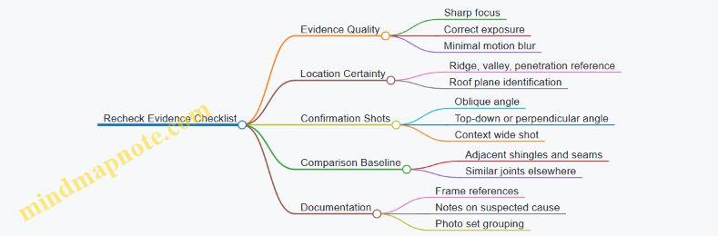
Practical Decision Rule for “Recheck or Escalate”
If the second pass confirms the same boundary, seam, or gap from a different angle, treat it as a real finding and document it with context. If the second pass turns the issue into a shadow, pattern variation, or inconsistent boundary, downgrade it to “uncertain” and recheck again only if it affects a drainage path or a critical penetration.
6. Land Surveying and Site Measurement for Home Use
6.1 Defining Survey Goals for Boundaries, Slopes, and Layout
A good survey starts with decisions, not with flying. Before you take off, define what “done” means for boundaries, slopes, and layout. Consumer drones can capture useful geometry, but your goals determine what data you must collect, how you should fly, and how you’ll interpret results.
1) Start with the Decision You Need
Write the outcome as a single sentence: “I need a plan that helps me decide X.” Examples:
- Boundaries: “I need a map showing where my fence line likely sits relative to known markers so I can plan a repair without guessing.”
- Slopes: “I need a slope profile to decide whether water will drain toward the house or away from it.”
- Layout: “I need a level reference to place a shed pad and confirm the corners are square.”
Then list the constraints that affect accuracy:
- Tolerance: how wrong can the result be and still be useful?
- Scale: are you mapping a small backyard or a wider site?
- Environment: trees, uneven ground, reflective surfaces, and narrow access paths.
2) Define Boundaries Goals Carefully
Boundary work is sensitive because “where the line is” may depend on legal records and survey monuments, not just what looks straight.
Set boundary goals in two layers:
- Geometric reference: where your drone-derived model places visible features (fence posts, corners, driveway edges).
- Legal alignment: how those features relate to boundary evidence you already have (existing monuments, recorded corner coordinates, or measured offsets).
A practical approach is to aim for “feature-to-reference” mapping rather than claiming the drone found the legal boundary. For example, you can produce a plan that shows fence posts relative to a known corner marker you measured on the ground.
3) Define Slope Goals with Measurement Meaning
Slopes are about gradients and drainage behavior, so define what you’ll compute.
Choose one of these slope goal types:
- Surface slope: how the ground tilts across a patch (useful for drainage).
- Elevation change: how much height difference exists between two points (useful for grading decisions).
- Cross-slope: how a driveway or walkway tilts sideways (useful for water runoff).
Example goal statement:
- “I need the elevation difference between the top of the driveway and the garage threshold, plus the slope across the driveway width.”
To make results interpretable, decide the sampling area. A slope over a tiny patch can be misleading if it sits on top of a local bump; a slope over a larger area can hide problems. Pick an area that matches the real drainage path you care about.
4) Define Layout Goals with Geometry and Level
Layout tasks require repeatable geometry: distances, angles, and level references.
Split layout goals into three measurable components:
- Plan geometry: corner positions, offsets from existing structures, and alignment to edges.
- Leveling: consistent elevation for a pad or base.
- Square and alignment: right angles and parallel lines.
Example goal statement:
- “I need to place a shed so its corners are 3.0 m from the fence line and the pad is level within 10 mm across the footprint.”
If your drone workflow produces relative elevations, you still need a ground reference point. Decide which point becomes your “zero” and how you’ll verify it with a simple ground check.
5) Mind Map for Survey Goal Definition
Mind Map: Defining Survey Goals
6) Translate Goals into Data Requirements
Once goals are clear, you can specify what to collect.
- For boundaries, prioritize consistent capture of corner features and any known reference points. If you can’t see a corner from the air due to trees, plan a ground measurement or choose an alternate vantage.
- For slopes, ensure the area is covered with overlap so the model doesn’t “smooth away” the very gradients you’re trying to measure.
- For layout, capture enough imagery to reconstruct corners and edges, then verify the final critical dimensions on the ground.
7) Example: One Yard, Three Goals
Imagine a backyard where you want to (1) repair a fence, (2) confirm drainage, and (3) place a small patio.
- Boundary goal: map fence posts relative to a known corner marker you measured with a tape.
- Slope goal: compute elevation change from the back corner to the downspout direction, using a drainage-relevant sampling area.
- Layout goal: set patio corners at fixed offsets from the house wall and confirm the pad level using one ground reference point.
Each goal points to different “done” criteria, so you avoid the common mistake of treating one flight as if it serves every purpose equally well.
6.2 Establishing Ground Control Points and Reference Markers
Ground control points (GCPs) and reference markers are the “anchors” that help your drone images line up with real-world measurements. Without them, you may still get a pretty model, but distances and boundaries can drift—sometimes by enough to matter when you’re marking a fence line or checking a slope.
Core Idea of Ground Control
A GCP is a clearly identifiable point on the ground with known coordinates in your chosen reference system. A reference marker is a point you can locate consistently to help validate or scale your results. In home surveying, you usually use a practical mix: a few GCPs for alignment and several check points to confirm accuracy.
What “Known” Means in Practice
“Known” can mean measured with a tape and compass for rough work, or measured with GNSS for higher confidence. For most household tasks, you can treat coordinates as relative to a local origin you define on site. The key is consistency: every measurement and every photo alignment step must use the same origin and units.
Choosing a Coordinate Approach
Start by deciding how you’ll express positions:
- Local grid: Pick an origin corner near the work area, then measure eastings and northings in meters or feet.
- GPS coordinates: Use the drone app or a GNSS receiver to record latitude and longitude.
Local grids are often easier for roof-adjacent yards because you can measure directly with a tape and keep everything in one unit system.
Selecting Ground Control Locations
Good GCPs are:
- Visible from multiple flight angles: Place them where the drone can see them from at least two directions.
- Spread out: Use corners and edges of the area you want to measure.
- Stable and unambiguous: Avoid spots that move, like loose gravel, tall grass, or freshly disturbed soil.
A typical home site might use 4 GCPs at the corners of a rectangular area plus 2 check points near the middle edges.
Building Markers That the Drone Can Actually See
Use markers that contrast with the ground and have a clear center.
- Target boards: Flat boards with a high-contrast pattern, placed on firm ground.
- Cross markers: A printed or painted cross with a defined center point.
- Temporary stakes with a visible top: Useful when you can’t place a board, but ensure the drone can see the top clearly.
Measure the center point of each marker, not the edge. If you use a board, mark the exact center with a small dot and keep that dot visible during measurement.
Measuring and Recording Ground Control Points
For each GCP, record:
- Point ID: Example GCP-1, GCP-2, etc.
- Coordinates: Easting and northing from your origin, or GPS coordinates.
- Marker description: Board size, orientation, and where the center is.
- Height reference: If you need elevations, record the marker center height above a known datum.
A simple workflow is: measure coordinates first, then place targets, then confirm visibility with a short hover test.
Example: Local Grid Setup for a Fence Line
- Choose an origin at the southwest corner of the fence area.
- Measure 12.0 m east to the southeast corner and 8.0 m north to the northwest corner.
- Set GCP-1 at the origin corner, GCP-2 at the southeast corner, GCP-3 at the northwest corner, and GCP-4 at the northeast corner.
- Add check points at the midpoint of the north and east edges.
When you later process images, the software uses the GCP coordinates to align the model, and the check points tell you whether the alignment is behaving.
Mind Map: Ground Control Workflow
Common Failure Modes and Fixes
- Markers placed too close together: The model may align but scale can wobble. Spread GCPs toward corners.
- Markers partially hidden: If a target is only visible in one flight direction, alignment weakens. Reposition or add a second viewing angle.
- Center point ambiguity: If you measure the edge instead of the center, you’ll introduce a systematic offset. Re-mark the center and re-measure.
- Inconsistent units or origin: Mixing feet and meters is a classic way to get “almost right” results. Write units on the field sheet and stick to them.
Practical Checklist Before You Fly
- You can name every marker center clearly.
- You have recorded coordinates for each GCP before processing.
- You have at least two check points that are not used as GCPs.
- You’ve confirmed visibility with a short test flight or camera preview.
With solid ground control, your later survey outputs become more than a visual record—they become measurements you can trust enough to act on.
6.3 Collecting Overlap Image Sets for Accurate Reconstruction
Accurate reconstruction starts long before you press “record.” Overlap image sets mean you capture the same features from multiple angles so the software can match points between photos. Think of it as giving the drone a consistent visual “fingerprint” to recognize, not just a pile of pictures.
Foundational Concepts That Make Overlap Work
Overlap types. Use two kinds of overlap: forward overlap (between consecutive frames along the flight path) and side overlap (between parallel flight lines). Forward overlap helps the system track motion across time; side overlap helps it connect neighboring strips.
Why overlap matters. Reconstruction algorithms need repeated views of edges, corners, and texture. A roof has plenty of such features—shingle edges, ridges, valleys, vents, and flashing—so it’s a good subject. A blank wall of paint is harder because there are fewer stable features to match.
Ground sampling distance. Your image resolution on the ground depends on altitude and camera settings. If you fly too high, features become too small to match reliably. If you fly too low, you may run out of battery or create excessive blur from vibration. The goal is consistent detail across the whole area.
Planning the Capture for Reliable Matches
Choose a flight pattern. For roof and yard measurement, a grid or parallel strips usually work best. Keep the camera facing downward with minimal yaw changes so the overlap stays predictable.
Set consistent speed and altitude. Sudden speed changes stretch the overlap unevenly. Uneven overlap forces the software to guess where features should appear, which increases mismatches.
Use a stable camera mode. Prefer manual exposure settings when lighting is consistent. Auto exposure can shift brightness between frames, making the same surface look different and reducing match quality.
Account for obstructions. Chimneys, trees, and skylights create “feature deserts” where the camera can’t see the same surfaces from all angles. Plan extra passes around these areas so the system still has enough shared views.
Practical Overlap Targets and How to Apply Them
A common starting point is about 70–85% forward overlap and about 60–80% side overlap for detailed reconstruction. Use these as a baseline, then adjust based on texture and motion.
- More overlap when texture is low. If the roof is uniform metal with few visible edges, increase overlap to give the matcher more chances.
- More overlap when wind is present. Wind causes micro-drift and slight angle changes. Extra overlap compensates for that by increasing the number of shared views.
- Less overlap when you’re already getting sharp, consistent detail. Too much overlap wastes time and can increase processing load without improving accuracy.
Step-by-Step Capture Workflow
- Start with a test strip. Fly one short strip over a representative section of the roof or site. Review sharpness and check that features remain crisp across the strip.
- Confirm overlap visually. Scrub through the photos and look for stable landmarks: ridge lines, vent bases, gutter corners, or fence posts.
- Adjust altitude before expanding coverage. If features look small or blurry, change altitude or speed rather than trying to “fix it later” with more photos.
- Fly parallel strips with consistent spacing. Maintain the same camera tilt and heading so side overlap stays within your target range.
- Add a perimeter pass. A boundary pass helps connect the outer edges where the reconstruction otherwise has fewer neighboring images.
- Include oblique angles when needed. For tall features like chimneys or dormers, add a short angled pass so those surfaces appear in multiple views.
Mind Map: Overlap Image Sets for Reconstruction
Example: Roof Coverage with Overlap That Actually Connects
Imagine you’re reconstructing a small roof section with vents and a skylight. You fly a first strip along the ridge, keeping altitude steady and speed moderate. After reviewing the strip, you notice that the vent edges are sharp and appear in many consecutive frames—good forward overlap.
Next, you fly a second strip parallel to the first, offset so the skylight frame and nearby shingles appear in both strips. That’s your side overlap doing its job. Then you add a short perimeter pass around the roof edges so the outer ridge and eaves aren’t left with only one neighboring strip.
Finally, you add an oblique pass aimed at the chimney and skylight faces. Without it, those vertical surfaces might only appear from one direction, leaving gaps in the reconstruction where the software can’t find enough matching points.
Example: When Overlap Isn’t the Problem
Suppose you captured plenty of images with high overlap, but the reconstruction looks “chunky,” with misaligned roof planes. Before increasing overlap again, check for blur and exposure shifts. If the photos show motion blur at the same time the drone drifted, the matcher can’t reliably identify corners. If brightness changes dramatically between frames, manual exposure or consistent lighting conditions can improve matching more than adding more overlap.
Overlap is a tool, not a magic spell. When overlap, sharpness, and consistent camera behavior line up, reconstruction becomes a straightforward consequence of good data.
6.4 Generating Maps and Interpreting Outputs for Practical Decisions
A map is only useful if it answers a question you actually have. In home surveying and roof-adjacent work, your questions usually fall into three buckets: “Where is it?”, “How big is it?”, and “What changed or needs attention?”. The workflow below turns overlapping drone imagery into practical outputs, then translates those outputs into decisions you can act on.
From Images to a Usable Map
Start with the raw capture plan, because mapping quality is mostly decided before you press record. Use consistent overlap so the software can match features between frames. Keep the camera orientation steady and avoid sudden yaw changes; your goal is predictable geometry, not artistic variety.
When you generate a map, you typically produce one or more of these:
- Orthomosaic: a top-down image corrected for perspective, useful for measuring distances and marking locations.
- 3D model or mesh: a surface representation, useful for visualizing slopes and roof geometry.
- Point cloud: the underlying measurement points, useful for checking density and alignment.
A practical rule: if you need measurements, prioritize the orthomosaic and the coordinate system it uses. If you need shape understanding, prioritize the 3D model.
Coordinate Systems and Scale That Don’t Lie
Most consumer workflows output something in an arbitrary coordinate frame unless you add reference. If you skip reference, the map may look convincing while being wrong in scale.
Use one of these approaches:
- Relative measurements: good for “compare A to B” tasks, like identifying which section of a roof is steeper.
- Scaled measurements: required for “how far” decisions, like estimating the length of a fence line.
- Georeferenced outputs: required when you need alignment to real-world coordinates, like matching a survey point to a property marker.
If your drone app offers ground control points or scaling tools, use them when accuracy matters. For example, if you know the distance between two known fence posts is 18.0 ft, you can scale the model so the orthomosaic distances become meaningful.
Interpreting Outputs Like a Skeptic
Interpreting a map is less about trusting colors and more about checking consistency.
First, verify alignment quality. Look for obvious mis-registrations: duplicated edges, warped roof lines, or features that “slide” between frames. A small amount of blur can be acceptable; systematic drift usually isn’t.
Next, check measurement plausibility. If the orthomosaic says a walkway is 2 ft wide but your eyes and tape measure say 4 ft, treat the output as suspect. Measurement errors often come from insufficient overlap, poor lighting contrast, or moving objects during capture.
Then, confirm coverage completeness. A map can be accurate where it has data and wrong where it doesn’t. For roof work, pay attention to valleys, eaves, and areas behind chimneys where the drone may have trouble seeing.
Practical Decisions Mapped to Output Types
Use the output that matches the decision.
- Roof inspection decisions: Use orthomosaic for locating features and building a “photo index” of problem areas. Use 3D model for slope cues and to understand where water likely collects.
- Land survey decisions: Use orthomosaic for distances and alignment to markers. Use point cloud density checks to ensure the model isn’t guessing in low-texture areas like bare soil.
- Security patrol decisions: Use orthomosaic for route planning and identifying entry points. Avoid relying on 3D shape alone for precise location claims.
A concrete example: you suspect a gutter section is misaligned. Generate an orthomosaic, mark the suspected segment, and measure the offset relative to a known straight reference like a fascia edge. Then cross-check with the 3D model to ensure the “offset” isn’t just a perspective artifact.
Mind Map: Generating Maps and Interpreting Outputs
Example Workflow for a Roof Measurement Decision
You want to estimate whether a roof section has a noticeable dip near a valley.
- Capture a grid that covers the valley and adjacent ridges with consistent overlap.
- Generate a 3D model and orthomosaic.
- Confirm alignment by checking that ridge lines and valley edges match across the model.
- Use the orthomosaic to mark the valley centerline and the two comparison points on either side.
- Use the 3D model to compare relative elevation along that centerline.
- Convert the result into a decision: if the dip is consistent across multiple points and not just one blurry patch, schedule a targeted inspection; if it appears only in a low-data area, re-capture that region.
This approach keeps you from treating a pretty map as a measurement instrument. You’re using the map to guide where to look, and using checks to decide whether the map is trustworthy enough to act on.
6.5 Verifying Measurements with Ground Checks and Error Review
Ground checks turn “looks right” into “is right.” When you measure a site with a consumer drone, you’re combining camera geometry, flight stability, positioning, and software assumptions. Verification is how you catch the parts that quietly disagree.
Core Idea of Ground Verification
Start with two questions: What measurement matters most, and what error would change a decision? For example, if you’re estimating a fence line, a 2–3 cm error might be fine for planning, while a 20 cm error could put a post in the wrong place. Verification focuses effort where it counts.
A practical workflow is:
- Pick reference points you can measure on the ground.
- Compare drone-derived results to those references.
- Quantify error patterns, not just a single number.
- Decide whether to re-fly, re-process, or accept with documented limits.
Choosing Ground Check Points
Use points that are:
- Stable: not moving, not soft, not likely to shift between flights.
- Distinct: corners, marked stakes, utility covers, or painted edges.
- Measurable: accessible with a tape, level, or total-station alternative.
A simple setup for a home boundary check uses three stakes: one near each end of the area and one in the middle. If you only check one point, you can’t tell whether errors are local (bad point) or systematic (whole model).
Measuring Ground Truth
Ground truth can be tape-based, level-based, or instrument-based. Tape measures are fine if you control technique:
- Measure from the same physical feature consistently.
- Keep the tape taut and aligned.
- Record the measurement method and any offsets (like measuring to the edge of a curb rather than the curb center).
For height checks, use a level and a consistent datum. For instance, measure vertical distance from a known ground mark to a roof edge or a stake top. If you can’t reach the exact point, measure to a nearby reference and note the offset.
Comparing Drone Outputs to Ground Checks
When you compare, compare like with like.
- If the drone model gives coordinates, convert them into distances you care about.
- If it gives elevations, verify the datum used by the software.
A useful comparison table for three check points:
| Check Point | Ground Distance/Height | Drone Result | Difference | Sign Meaning |
|---|---|---|---|---|
| A | 12.40 m | 12.36 m | -0.04 m | Drone short |
| B | 8.15 m | 8.22 m | +0.07 m | Drone long |
| C | 1.20 m | 1.18 m | -0.02 m | Drone low |
Differences with mixed signs often indicate a general scale or alignment issue. Differences that all lean the same direction can indicate a datum mismatch or a consistent offset.
Mind Map: Error Review Logic
Interpreting Error Patterns
-
Random scatter: If errors jump around with no clear direction, your model may be limited by image quality or positioning noise. Improve overlap and reduce motion blur on the next processing run.
-
Systematic bias: If every check is consistently high or low, suspect datum or scale. A common cause is using a reference height that doesn’t match the software’s assumed zero. Fix the reference inputs and re-run processing.
-
Local outliers: If one corner is off while the rest agree, that point may be poorly visible in images, blocked by vegetation, or measured to a different physical edge than the drone used. Re-check that specific marker and confirm you measured the same feature.
Example: Fence Line Verification
You fly a rectangular area to estimate fence post spacing. You place three ground stakes along the intended line and measure distances between them with a tape.
- Ground: A–B = 6.00 m, B–C = 6.00 m
- Drone: A–B = 5.94 m, B–C = 6.08 m
The total length A–C becomes:
- Ground: 12.00 m
- Drone: 12.02 m
Even though the total is close, the split distances show a local distortion around point B. That suggests the model is bending near the middle, often caused by weaker image coverage or a less stable camera angle over that segment. The fix is to reprocess with stricter alignment settings or re-fly with more consistent overlap over the middle stake.
Decision Rules for Accepting or Reworking
Set thresholds before you start. For instance:
- If all check points are within your tolerance, accept and document the max error.
- If one point exceeds tolerance by a lot, treat it as an outlier and investigate that point first.
- If multiple points exceed tolerance in the same direction, re-check datum and reference inputs.
Ground checks are not about perfection; they’re about knowing what your measurements can responsibly support. When you can explain the error pattern in plain language, you can trust the result more than the number alone.
7. Security Patrol and Perimeter Monitoring with Drones
7.1 Setting Up Patrol Routes for Driveways, Gates, and Perimeters
A patrol route is just a repeatable path that matches what you want to notice: who enters, what changes, and where you should look again. Start by defining the “coverage goal” in plain terms, then translate it into a flight path, camera behavior, and a checklist you can run the same way every time.
Define Patrol Coverage Goals
Write three short goals before you touch the controller:
- Entry detection: “I want to see vehicles approaching the gate and pedestrians crossing the driveway.”
- Change detection: “I want to notice new objects near the fence line or gate hardware.”
- Evidence capture: “I want usable faces/vehicle details when something unusual happens.”
Then decide what “good enough” looks like. For example, if your driveway is 20 meters long, a route that keeps the camera too high may show motion but not details. A route that stays too low may lose context. Your goal determines your altitude band.
Map the Perimeter into Zones
Split the property into zones so your route doesn’t treat everything the same. A simple zoning approach works well:
- Zone A: Approach corridor (street-to-driveway line)
- Zone B: Gate and latch area (hinges, keypad, lock)
- Zone C: Driveway parking area (where vehicles stop)
- Zone D: Fence and side yard (gaps, gates, walls)
For each zone, note the “must-see” features. If you can’t list them, the route will be vague and your review will be slow.
Choose Route Geometry That Matches Real Movement
Use geometry that mirrors how people actually move.
- Driveway and approach: a slow arc or two-pass line that captures approach from two angles.
- Gate: a tight loop that repeatedly frames the latch and keypad.
- Perimeter: a rectangular or L-shaped perimeter track with consistent spacing from the fence.
A practical rule: if you want to compare “before and after,” keep the camera angle and distance consistent. That means repeating the same path segment, not improvising.
Set Altitude and Camera Behavior for Usable Details
Patrol routes fail when the camera is either too high to identify details or too low to maintain stable framing.
- Altitude band: Pick a band that keeps the subject large enough in the frame. For many driveways, that means staying low enough to read vehicle shapes and gate hardware, while still maintaining safe clearance from trees and walls.
- Camera angle: Use a consistent downward tilt. If your drone supports it, lock the gimbal pitch so the horizon doesn’t drift between passes.
- Speed: Slow enough to reduce motion blur during review. If you’re reviewing later, speed is less about “getting there” and more about “capturing usable frames.”
Plan for Obstacles and Safe Margins
Before you fly, identify obstacles that can break a route: power lines, branches, tall posts, and reflective surfaces near windows.
- Keep a lateral margin from fences and walls so the drone doesn’t “graze” edges.
- Avoid flying directly under overhangs where GPS can degrade and where the drone may lose stable attitude.
- If your drone has obstacle sensing, treat it as a last line of defense, not the route planner.
Build a Route with Repeats and Checkpoints
A good patrol route includes repeats because it improves your odds of catching the moment that matters.
- Checkpoint 1: approach corridor entry
- Checkpoint 2: gate latch close framing
- Checkpoint 3: driveway parking area
- Checkpoint 4: side fence segment
Between checkpoints, use smooth transitions so the camera doesn’t jerk. If you’re using waypoints, keep waypoint spacing consistent within each zone.
Mind Map for Route Setup
Patrol Route Setup Mind Map
Example Route for a Typical Driveway and Perimeter
Assume a property with a driveway leading to a gate, then a fence around three sides.
- Segment 1 (Approach corridor): fly a slow arc parallel to the driveway, ending with the gate centered.
- Segment 2 (Gate loop): perform a small loop that passes the latch and keypad area twice, keeping the camera angle steady.
- Segment 3 (Driveway parking area): run a straight line down the driveway at a consistent distance, then return along a slightly offset line for a second angle.
- Segment 4 (Perimeter track): fly an L-shaped perimeter path that covers the side fence and the rear corner, with a consistent offset from the fence line.
After the first run, review the checkpoint frames. If the gate latch is too small, adjust altitude or distance for Segment 2. If the side fence shows motion but not details, adjust speed and camera angle for Segment 4.
Quick Checklist Before Each Patrol
- Route matches zones and checkpoints
- Camera pitch is consistent across segments
- Speed is slow enough for review clarity
- Obstacles and margins are confirmed
- You can repeat the same path without improvising
A patrol route is successful when you can review it quickly and confidently say, “This is what I expected to see at each checkpoint.”
7.2 Night and Low Light Considerations for Visible and Thermal Cameras
Night work changes what “good footage” means. Your visible camera needs enough light to show edges and textures, while your thermal camera needs the scene to have meaningful temperature contrast. Both systems also behave differently with autofocus, exposure, and motion, so you plan for those differences instead of hoping the drone “figures it out.”
Foundational Differences Between Visible and Thermal
Visible imaging records reflected light. If the scene is dark, the camera compensates by increasing exposure or gain, which can make images noisy and blurrier. Thermal imaging records emitted heat, so it can still work when visible light is scarce, but it depends on temperature differences between objects and their surroundings.
A practical way to remember the tradeoff: visible helps you recognize details like shingles, vents, and labels; thermal helps you spot anomalies like heat loss, moisture-related cooling, or warm equipment. In low light, you often use both: visible for context, thermal for detection.
Preflight Setup for Low Light
Start with a consistent baseline so you can compare images across passes.
- Choose a stable flight plan. Fly slower than daytime to reduce motion blur and to give the camera time to settle exposure.
- Set camera behavior intentionally. If your drone offers manual exposure or fixed shutter options, use them. Auto exposure can “hunt” when the drone crosses bright porch lights or reflective surfaces.
- Check lens and sensor cleanliness. A small smear becomes a big problem at night because bright lights create flare.
- Plan for battery margin. Night flights often take longer due to careful positioning and repeated checks.
Visible Camera Techniques at Night
Visible cameras struggle when light is limited, so you manage exposure and motion.
- Control glare sources. Avoid flying directly toward strong lights. If you must pass near them, keep the light at the edge of frame rather than centered.
- Use steady framing. Hold altitude and yaw smoothly. Sudden yaw changes can cause the camera to re-expose mid-shot.
- Prefer shorter, repeated clips over one long take. Short takes reduce the chance that exposure shifts during the entire sequence.
Example: For a roof edge inspection at dusk, capture a slow orbit at a fixed height with the camera facing the eaves. Then repeat the same orbit after the porch light turns on. Compare the two sets to see whether exposure changes are masking details.
Thermal Camera Techniques at Night
Thermal performance depends on contrast and surface conditions.
- Let the drone and camera stabilize. Temperature changes between the drone and the environment can cause early frames to look inconsistent. Wait a moment before starting your capture.
- Mind surface emissivity differences. Painted wood, metal, and wet surfaces can show different apparent temperatures even if they are similar in reality. Use visible context to interpret what you’re seeing.
- Avoid wind-driven temperature mixing. Breezes can cool surfaces unevenly, creating patchy thermal patterns that look like defects.
Example: For a thermal check of a wall near a window, capture one pass when the area is calm and another pass after a short period of normal household activity. If a “hot rectangle” only appears during airflow changes, it may be airflow effects rather than a building issue.
Managing Focus, Exposure, and Image Stability
Both camera types benefit from predictable settings.
- Reduce autofocus surprises. If the drone uses autofocus, give it a clear target and avoid rapid changes in distance. For close work, keep the drone’s position steady long enough for focus to settle.
- Use consistent distance. Thermal readings can vary with distance due to optics and scene scale. Keep your framing similar between runs.
- Stabilize your motion profile. Smooth inputs matter more at night because the camera has less margin to correct blur.
Scene Planning for Meaningful Results
Night scenes can fool you if you don’t control the environment.
- Use reference points. Include a consistent landmark in visible frames so you can align thermal anomalies with the correct location.
- Separate “detection” from “documentation.” First fly to find anomalies, then slow down for a second pass that prioritizes clarity and repeatability.
- Watch for reflective surfaces. Wet pavement and shiny metal can create confusing visible glare and can also affect thermal interpretation.
Mind Map: Night and Low Light Workflow
Quick Example Pairing Visible and Thermal
For a perimeter security patrol at night, first capture visible footage of gates and paths under existing lighting. Then run a thermal pass at the same general altitude, focusing on warm objects and unusual cold patches. If you see a thermal anomaly near a fence post, use the visible landmark to determine whether it aligns with a utility box, a sheltered corner, or a reflective surface that could distort interpretation.
Practical Checklist for the First Night Run
- Camera settings are consistent across passes.
- Motion is slower and smoother than daytime.
- Visible glare sources are managed.
- Thermal capture starts after stabilization.
- Landmarks are included for alignment.
- You repeat any surprising finding before treating it as real.
7.3 Operating With Discretion for Privacy Respectful Monitoring
Privacy-respectful monitoring starts with a simple rule: collect only what you need, and treat it like it could end up in someone else’s hands. That mindset shapes your choices before you ever power on the drone.
Foundational Principles for Discretion
First, define the purpose in plain language. If your goal is “check the gate latch after a storm,” you do not need to record faces on the sidewalk. Write the purpose as a short sentence and keep it visible in your planning notes.
Second, limit collection. Use the smallest camera field of view that still captures the target area, and avoid hovering over windows, backyards, and private entrances. If your drone supports it, choose a lower-resolution or narrower capture mode when high detail is unnecessary.
Third, control exposure time. A slow pass across a driveway is usually less intrusive than repeated circling at the same height. Plan one or two clean passes, then land and review.
Fourth, treat bystanders as part of the environment. If someone approaches while you’re recording, stop capturing and reposition to a safer, less intrusive angle.
Practical Planning That Reduces Privacy Risk
Start with a “view map” of your property and nearby spaces. Identify where the camera can see into private areas. For example, a roofline camera angle might capture a neighbor’s second-story window even if you never intend to. Adjust your route so the drone stays oriented toward your target and away from sensitive sightlines.
Next, set altitude and distance intentionally. Staying farther away generally reduces the chance of identifying people while still showing the condition of gates, fences, and exterior fixtures. If you need detail, prioritize short, targeted captures rather than long continuous recording.
Finally, decide in advance what you will do with the footage. If you only need a quick visual check, you can avoid saving full-resolution video and instead capture a few stills. If you do save media, store it in a dedicated folder labeled by task and date, so you’re not mixing it with unrelated family photos.
Mind Map: Privacy Respectful Monitoring Workflow
Examples You Can Use Immediately
Example: Gate and driveway check You want to confirm whether a gate is fully latched. Plan a single pass parallel to the fence line from a distance that shows the latch area clearly. Avoid looking down into adjacent yards. If a neighbor walks into the camera’s view, pause recording and shift the drone to a position that keeps the camera pointed at the gate.
Example: Perimeter scan after a break-in report You’re looking for signs of forced entry on your own property. Fly a route that stays above your property boundary and keeps the camera pointed inward. Capture only the locations that show damage or entry points. If you accidentally record a neighbor’s car in the background, do not share it; keep the footage private and delete it once you’ve documented your own property.
Example: Thermal check without unnecessary faces Thermal images can reveal more than you expect, especially at night. Use thermal capture only when you can aim it at exterior structures you own. Keep the drone from lingering over walkways where people might be present, and avoid scanning areas that include neighboring windows or patios.
Data Handling Rules That Prevent Accidental Overreach
When you finish, review footage quickly and remove what doesn’t support the task. If you captured people unintentionally, keep the minimum necessary record for your own documentation, then delete the rest. Use clear folder names like “Patrol-FrontGate-2026-04-15” so you can find what you need without searching through everything.
Sharing should be narrow and purposeful. If you need to show a contractor a damaged latch, crop or frame the view so it focuses on your property. If you need to provide evidence to authorities, share only the relevant clips and avoid sending full raw recordings that include unrelated areas.
Advanced Discretion Tactics for Real-World Situations
If you must fly near boundaries, use “camera discipline.” Move the drone with the flight controls, but keep the camera orientation steady and intentional. Don’t pan around to satisfy curiosity; pan only to confirm the specific item you’re documenting.
If wind or GPS drift causes your drone to drift toward sensitive areas, correct immediately rather than waiting. Privacy-respectful monitoring is not just about what you capture; it’s also about how quickly you stop when the situation changes.
Finally, keep a short internal log: what you checked, where you flew, and what you saved. This helps you stay consistent and prevents the common mistake of saving everything “just in case,” which is exactly how privacy gets messy.
7.4 Recording Evidence With Time Stamps and Location Context
When you record evidence for security patrol, the goal is simple: someone else should be able to understand what happened, when it happened, and where it happened—without guessing. Time stamps and location context are the backbone of that clarity.
Foundational Concepts for Evidence Clarity
Start by treating every capture as a “claim.” A claim needs three supporting details: the moment, the place, and the basis for interpretation. For example, “Gate latch appears loose” is stronger when paired with a time stamp, a consistent camera view, and a location reference such as GPS coordinates or a known landmark.
Time stamps should be consistent across your drone app, your controller, and any additional device you use. If your phone clock is off by even a few minutes, your evidence becomes harder to align with other observations.
Location context should be stable and repeatable. “Near the back fence” is vague; “north side of the driveway, 6 meters from the gate hinge” is usable. If you cannot measure, use a repeatable reference like “same waypoint as patrol run 3” or “same camera angle relative to the front porch light.”
Mind Map: Evidence Fields and How They Connect
Systematic Workflow Before You Fly
-
Set a single time standard. Use the drone app’s time zone setting and keep it aligned with your controller and phone. If you must use a date, use one like 2026-03-05 rather than relying on “today” in notes.
-
Choose location anchors. Pick at least two anchors per patrol: one GPS-based and one visual. GPS anchors help with exact placement; visual anchors help when GPS is weak under trees or near buildings.
-
Define your camera orientation rule. Decide how you will label “left/right” in your notes. For instance, “left” always means the drone’s left when facing outward from the property center. This prevents the classic evidence mismatch where two people interpret the same frame differently.
Capturing Evidence During the Patrol
Record evidence in layers so you can reconstruct events even if one layer is incomplete.
-
Wide context first. Start with a short establishing sequence showing the driveway, gate, or boundary line. This gives location context for later close-ups.
-
Then capture the specific issue. Move to the area of interest and capture stills and short video clips. If you see something like a door gap, capture from two angles so the viewer can judge depth.
-
Include a repeatable reference in-frame. If possible, keep a fixed object visible, such as the gate hinge, a corner post, or a porch light. That object becomes your “visual coordinate.”
-
Use consistent time stamps. If your app embeds time in metadata, keep the metadata intact by avoiding unnecessary re-exports that strip fields. If your app does not embed it reliably, add a manual time stamp in your notes immediately after capture.
Evidence Notes That Don’t Require Mind Reading
For each capture, write a compact note with three parts: Observation, Location, and Reasoning.
- Observation: what you can see.
- Location: waypoint name or GPS plus a landmark.
- Reasoning: why you think it matters, without overreaching.
Example note:
- Observation: “Gate latch appears not fully seated.”
- Location: “Waypoint GATE-01, north side; hinge visible in frame.”
- Reasoning: “Latch is angled outward compared to the last patrol run; hinge alignment matches prior establishing shot.”
Mind Map: Evidence File Naming and Organization

Practical Example: One Patrol, Two Captures
Assume you run a patrol on 2026-03-05.
-
Capture A (establishing): wide shot of the driveway and front gate.
- Time stamp: 09:14:32
- Location context: GPS 40.123456, -74.123456 plus “gate hinge visible.”
- Note: “Baseline view for later comparisons.”
-
Capture B (specific): close-up of the latch area.
- Time stamp: 09:16:05
- Location context: Waypoint GATE-01, same camera orientation as Capture A.
- Note: “Latch not fully seated; compare to Capture A for alignment.”
This pairing matters because Capture B alone could be anywhere. Capture A anchors the viewer to the correct place and makes the time gap meaningful.
Common Mistakes to Avoid
- Mixing time zones between devices.
- Changing camera orientation without noting it.
- Using vague location language when a waypoint or landmark can be used.
- Writing interpretation without observation. If you cannot point to what you saw, don’t claim what it means.
Quick Checklist for Each Evidence Item
- Time stamp recorded or verified.
- Location anchor included.
- Landmark or in-frame reference visible.
- Note contains observation, location, and limited reasoning.
- File saved under the correct patrol run folder.
7.5 Responding to Alerts with Safe Procedures and Clear Documentation
When your drone triggers an alert, treat it like a traffic light: first decide what it means for immediate safety, then decide what it means for your next steps. Alerts can be about control link, GPS quality, obstacle sensing, battery state, or camera-related issues. Your goal is to stabilize the aircraft, protect people and property, and preserve evidence so you can review what happened.
Foundational Priorities for Any Alert
- Protect people first. If anyone is within the drone’s potential path, slow down your actions and increase separation.
- Stabilize the aircraft. Use the controller’s standard “hover/return” behavior only when it is safe to do so.
- Reduce complexity. Don’t start changing multiple settings mid-alert. One action at a time.
- Document while the situation is fresh. Capture the alert message, time, and flight context before you power down.
A practical mindset: you’re not “fixing” the drone during the alert; you’re managing risk while the drone manages itself.
Safe Response Workflow
Step 1: Read the alert and identify its category.
- Link or control alerts: the drone may not respond normally.
- Navigation alerts: GPS/compass quality may be degraded.
- Battery alerts: power may be insufficient for the planned maneuver.
- Obstacle or flight path alerts: the drone may be detecting something unexpected.
Step 2: Choose the safest immediate maneuver.
- If you have clear space and stable control, switch to hover and assess.
- If you are near people or obstacles, prioritize moving away from the hazard before any return behavior.
- If battery is low, avoid aggressive repositioning; aim for the quickest safe path to landing.
Step 3: Confirm the environment.
- Check wind direction and gusts.
- Look for new hazards: a person stepping into frame, a gate opening, a vehicle moving.
- Verify the takeoff/landing area is still clear.
Step 4: Execute the next action with minimal changes.
- If the alert suggests navigation issues, avoid tight maneuvers and keep altitude steady.
- If obstacle sensing is involved, slow down and fly with wider margins.
Step 5: Land and secure.
- Land promptly when the alert indicates degraded safety margins.
- Power down only after the drone is on stable ground.
Clear Documentation That Actually Helps
Documentation should answer five questions: what, when, where, what you did, and what the drone reported. Keep it short and consistent.
Use a simple log entry format:
- Time: 2026-03-05 19:42
- Location: driveway perimeter, north side by the gate
- Alert text: “Remote controller signal weak”
- Drone state: hovering at ~10 m
- Your action: switched to hover, increased distance from people, initiated landing
- Outcome: landed safely, no contact
- Notes: wind gusts increased; nearby metal fence may have affected signal
Even if you’re not sure about the cause, record what you observed. Future you will thank present you.
Mind Map: Alert Response and Documentation
Examples for Common Patrol Alerts
Example: Weak Remote Controller Signal You’re running a perimeter patrol along a fence line. The alert appears while the drone is still moving slowly. First, switch to hover if you can maintain safe separation. Then increase distance from people and obstacles, and move the drone toward a clearer line-of-sight area. If the signal remains unstable, land rather than “testing” the link.
Documentation entry should include the fence and gate context, because those are the usual culprits for signal reflections and partial obstruction.
Example: Low Battery During a Thermal Check Thermal work often encourages you to hold position for stable readings. If a low-battery alert triggers, don’t keep hovering for “one more shot.” Move toward the landing area using the shortest safe route, keep altitude steady, and land. After landing, note whether the battery warning arrived earlier than usual, since that can indicate colder conditions or higher-than-expected wind.
Example: Navigation Quality Degraded Near Buildings If GPS or compass quality degrades while you’re near walls, reduce speed and avoid sharp turns. Hover long enough to confirm the drone is stable, then reposition to a more open area before continuing the patrol. If stability does not improve, end the flight and document the building proximity and time of day.
Post-Action Review Without Second-Guessing
After landing, review the recorded flight log and the alert message. Write one sentence on the likely contributing factors you observed, such as wind gusts, line-of-sight changes, or battery behavior. Then decide whether the session should end based on whether the safety issue repeats. The best documentation is the kind that prevents the same alert from becoming a recurring plot twist.
8. Thermal Checks for Moisture, Heat Loss, and Equipment Health
8.1 Understanding Thermal Camera Basics for Household Diagnostics
A thermal camera measures temperature differences and converts them into a color or grayscale image. The key idea for household diagnostics is that you are usually comparing “how warm” one surface is relative to another, not reading a perfect thermometer value. That comparison can still be very useful when you control the scene and understand what the camera is actually seeing.
What a Thermal Camera Measures
Most consumer thermal cameras detect infrared radiation and translate it into an image. Each pixel corresponds to a tiny area on the scene, and the camera estimates temperature using assumptions about how surfaces emit infrared energy. Two settings matter most for practical use: emissivity and reflected temperature.
Emissivity describes how strongly a material emits infrared compared with an ideal emitter. Matte painted drywall and asphalt shingles tend to have high emissivity, while shiny metal and glossy tiles can have low emissivity. Reflected temperature accounts for infrared energy bouncing off reflective surfaces from nearby objects. If you point the camera at a shiny gutter bracket, the “temperature” you see may be influenced more by what’s reflecting than by the bracket’s own heat.
Thermal Images Are Not Magic Thermometers
A thermal image is a map of estimated surface temperatures. Several factors can distort the map even when the camera is working correctly:
- Distance and focus: If the camera is out of focus, the pixel areas blur and edges smear, making hot and cool regions harder to interpret.
- Angle: Looking at a surface at a steep angle can change how much of the surface is visible and how reflections contribute.
- Air and smoke: Water vapor and dust can absorb and scatter infrared, especially over longer distances.
- Wind and sun: Outdoor scenes change quickly. A spot that looks “wrong” at one moment may normalize after clouds pass or wind shifts.
Emissivity and Reflections in Plain Language
Think of emissivity as “how much the surface tells the camera its own temperature.” High-emissivity surfaces behave more predictably. Low-emissivity surfaces behave like mirrors for infrared.
A practical workflow is to choose a reference area on the same surface type. For example, when checking a wall for insulation gaps, compare the suspect patch to nearby drywall rather than to a different material like brick or wood trim.
Color Palettes and What They Mean
Color palettes are for human interpretation. The palette does not change the underlying temperature estimates; it only changes how differences appear. A common mistake is to assume that “red means dangerous.” Instead, treat the palette as a scale and focus on relative patterns: edges, repeating shapes, and consistent hot or cold bands.
Scene Preparation for Reliable Household Checks
You get better results by controlling the environment more than by changing camera settings.
- Use a stable temperature difference: Indoors, turn off drafts and avoid opening doors during the scan. Outdoors, choose a time when the sun is not actively heating one side of the house.
- Allow surfaces to settle: After moving furniture or running HVAC, wait long enough for nearby surfaces to stop rapidly changing.
- Keep the camera steady: Move slowly and avoid sudden angle changes. If you must reposition, pause long enough for the image to stabilize.
Interpreting Patterns Instead of Single Spots
Household issues often show up as shapes:
- Cold spots in walls or ceilings can indicate missing insulation, air leakage, or thermal bridging.
- Warm spots near plumbing can indicate active flow, but also can reveal heat loss from pipes.
- Hot spots on electrical components can indicate poor connections or overloaded circuits, but you should treat this as a “check further” signal rather than a final diagnosis.
When you see an anomaly, confirm it by changing one variable at a time: angle slightly, reframe, and compare to adjacent areas of the same material.
Mind Map: Thermal Camera Basics for Household Diagnostics
Example: Finding a Drafty Wall Section
You suspect a wall is losing heat. Stand at a consistent distance and focus on the drywall surface. Scan slowly across the area and note whether you see a repeating cold shape, such as a vertical band near a stud line or a patch around an outlet.
Next, compare that region to nearby drywall that appears similar in texture and paint. If the cold region persists while the reference area stays relatively uniform, it’s more likely to be a real thermal difference rather than a camera artifact. If the “cold” area changes dramatically when you shift angle, reflections or emissivity differences may be dominating.
Example: Checking a Gutter for Heat Loss Clues
Gutters are often metallic or coated, which can reduce emissivity and increase reflection effects. Instead of trusting a single bright or dark spot, look for consistent patterns along the gutter line and compare sections made of the same material. If one segment looks very different from its neighbors, recheck from a slightly different angle and confirm whether the anomaly tracks with the gutter hardware or with nearby reflective objects.
Example: Interpreting a Warm Electrical Panel Area
A thermal camera can show warmer components, but temperature alone doesn’t identify the cause. Use the image to locate which area is warmer than its surroundings, then visually inspect safely from a distance using appropriate precautions. If the warm region is localized and repeatable across multiple scans under similar conditions, it’s a stronger indication that something is different at that component rather than a transient effect.
Quick Mental Checklist Before You Conclude Anything
- Is the anomaly a pattern or a single pixel?
- Are you comparing similar materials?
- Did you keep angle, distance, and focus consistent?
- Could reflections or sun/wind be driving the difference?
Thermal diagnostics work best when you treat the camera as a structured comparison tool. When you control the scene and interpret patterns, the images become practical evidence rather than just a colorful guess.
8.2 Preparing the Scene for Meaningful Thermal Comparisons
Thermal comparisons only work when the scene is controlled enough that temperature differences come from the subject, not from changing conditions. Think of it like taking photos in the same lighting: if the light keeps changing, you can’t trust the “before vs after.”
Foundational Principles for Comparable Thermal Frames
Start by separating two ideas: the drone’s thermal camera settings and the environment’s thermal behavior. Camera settings affect how temperatures are displayed; the environment affects what temperatures are actually present.
-
Use consistent distance and angle. Thermal resolution drops with distance, and angle changes the amount of surface area you effectively “see.” Example: if you inspect a roof vent from 10 m on the first pass, don’t switch to 6 m on the second pass.
-
Stabilize the scene before capture. Surfaces keep absorbing and releasing heat. Example: after walking around a driveway, wait a few minutes before capturing the thermal image of the concrete where your body heat may have warmed the area.
-
Control airflow and sun exposure. Wind and direct sun can shift surface temperatures quickly. Example: if one side of a house is in shade and the other is in sun, compare only within the same lighting condition, or capture both sides in the same sequence without long delays.
-
Keep the camera workflow consistent. Use the same measurement mode, palette, and any fixed parameters your app offers. If the app allows emissivity or similar surface settings, set them deliberately rather than letting the system guess.
Scene Preparation Checklist That Actually Prevents Bad Comparisons
Use this order so you don’t “fix” one variable while accidentally changing another.
-
Pick a comparison target and define the question. Are you checking moisture under siding, heat loss around a window, or an overheated component? Your question determines what “normal” looks like.
-
Choose a capture sequence. Do wide context shots first, then move to close detail. Example: capture the whole roof plane, then zoom in on suspected penetrations. This reduces the temptation to reframe and change distance mid-sequence.
-
Wait for thermal settling. If the subject was recently exposed to sun, rain, or airflow, give it time to reach a more stable state. Example: after a light shower, avoid immediate thermal capture of shingles; water evaporation can create misleading cool-warm patterns.
-
Avoid human interference. Don’t stand directly over the target or touch nearby surfaces between passes. Example: when checking a gutter line, keep your body and hands away from the section you plan to compare.
-
Use consistent background context. Background surfaces influence how you interpret contrast. Example: if you’re comparing two roof sections, ensure both are framed with similar sky and wall background so the contrast doesn’t trick your eyes.
Emissivity and Surface Reality
Thermal cameras estimate temperature from emitted infrared energy. Different materials emit infrared differently, so the same “true” temperature can appear different if emissivity is wrong.
- Use emissivity settings when available. Example: painted wood and bare metal can show different apparent temperatures even at the same physical temperature.
- Treat shiny surfaces carefully. Glossy metal can reflect infrared from surroundings, making it look hotter or colder than it is.
- When you can’t set emissivity, compare like with like. Example: compare one painted wall section to another painted wall section, not to a nearby metal panel.
Environmental Variables and How to Keep Them from Sneaking In
Wind, clouds, and time-of-day changes can alter surface temperatures faster than you think.
- Wind: If gusts are present, capture in shorter bursts and finish a target area before moving on.
- Cloud cover: If clouds pass over the sun, pause and resume only when conditions stabilize.
- Time between passes: Keep the interval short and consistent. Example: if you plan a “before and after” after a repair, capture both within the same general weather window.
Mind Map: Preparing the Scene for Meaningful Thermal Comparisons
Example Scenarios That Show the Logic
Example: Roof Vent Thermal Check
- Capture a wide shot of the roof plane first.
- Move to the vent area at the same distance you used for the first close pass.
- Wait a few minutes if the vent was recently warmed by sun.
- Compare the vent region to nearby roof sections with similar material and exposure.
Example: Window Heat Loss Around a Frame
- Choose a sequence where both the window frame and adjacent wall are in the same lighting condition.
- Avoid capturing immediately after the window was opened or after you handled the trim.
- Use consistent framing so the background wall doesn’t change contrast.
Example: Gutter Line Moisture Suspect
- Capture the gutter area and the adjacent fascia in one continuous sequence.
- Don’t stand over the suspect section between passes.
- If it rained recently, delay capture until evaporation effects calm down.
Quick Self-Audit Before You Trust the Images
Before leaving the scene, ask: Did I change distance, angle, or framing between passes? Did wind or sun conditions shift mid-sequence? Did the surface get recently warmed or cooled by my actions? If any answer is “yes,” redo the capture for that target area so the comparison is about the subject, not the circumstances.
8.3 Capturing Thermal Images with Correct Distance and Angle
Thermal images are less forgiving than visible-light photos because the camera is measuring surface temperature, not “what looks sharp.” Your job is to make the scene geometry and measurement conditions consistent enough that the colors mean something.
Start with What the Thermal Camera Actually Sees
A thermal camera reports temperature for pixels that correspond to surfaces in its field of view. That means distance and angle change which surface area fills the frame and how much of the path is blocked by air, glass, or dust. If you stand too far away, each pixel covers a larger patch of material, so small leaks, missing insulation, or localized moisture can blur into a general haze.
Choose Distance Using Frame Coverage, Not Guesswork
Pick a target: “I want the roof edge and the suspected wet area to fill most of the frame.” Then move until the feature occupies enough pixels to show shape. A practical rule is to capture a test shot at your intended distance, then zoom in on the preview to confirm the feature edges are distinct. If the edge looks like a soft blob, step closer and repeat.
Example: For a suspected gutter leak, stand so the gutter run and the wall below it fill the lower half of the frame. If the gutter is only a thin line, you’ll likely miss the exact spot where water is soaking the fascia.
Control Angle to Reduce Reflections and Measurement Confusion
Angle affects two things: how much of the surface is visible and how much reflected energy contaminates the reading. Many household surfaces are not perfect emitters, so the camera may “see” a mix of emitted heat and reflected surroundings. To minimize surprises, aim for a near-perpendicular view of the surface you care about.
For roof and wall checks, this often means approaching from the side rather than from straight below. If you must shoot at a steep angle, treat the image as a “where to look” map, not a precise temperature measurement.
Example: When checking a window frame for drafts, shoot with the camera as square to the frame as you can. If you shoot from a low angle, the frame edges may look warmer or cooler due to reflections from the ground and sky.
Use Consistent Camera Settings and Environmental Assumptions
Thermal cameras typically allow settings such as emissivity and reflected temperature compensation. If your drone app offers emissivity presets, choose the closest match to the surface type (painted wood, brick, metal, etc.). If it doesn’t, you still need consistency: use the same emissivity approach across before/after captures.
Also keep the scene conditions steady. Moving clouds, direct sun, and wind can change surface temperatures quickly. If you’re comparing images, capture them in the same general lighting and airflow conditions.
Example: For moisture checks on siding, take your “baseline” shot and your “recheck” shot within the same time window, avoiding times when sun hits one side of the house but not the other.
Build a Simple Capture Workflow That Prevents Rework
- Establish the target area in the live view and confirm it fills the frame.
- Set the angle to be as close to perpendicular as practical.
- Take a test image and inspect whether edges and transitions are visible.
- Adjust distance in small steps until the feature shape is clear.
- Lock in the capture and avoid changing both distance and angle at the same time.
This sequence matters because changing both variables at once makes it hard to tell whether the improvement came from better framing or better geometry.
Mind Map: Distance and Angle for Meaningful Thermal Images
Example: Roof Edge Thermal Check with Two Passes
Pass 1 focuses on coverage: fly to a position where the eaves, fascia, and the suspected problem zone occupy most of the frame. Shoot from an angle that faces the roof edge as directly as possible.
Pass 2 focuses on clarity: move closer slightly, keeping the angle similar, and capture again. If the first pass shows a general warm band but the second pass reveals a sharper boundary, you’ve improved the measurement usefulness rather than just the aesthetics.
Quick Troubleshooting for Common Geometry Problems
- Everything looks uniformly warm or cool: you likely lost surface detail due to distance or angle; step closer and re-center the target.
- Edges look “wrong” compared to nearby surfaces: your angle may be introducing reflections; shift to a more square view.
- Before/after images don’t match: distance, angle, or emissivity assumptions changed; repeat using the same workflow and capture window.
Correct distance and angle turn thermal color from “interesting” into “actionable.” When you treat framing and geometry as part of the measurement, you spend less time arguing with your own images and more time fixing what you found.
8.4 Interpreting Hot Spots and Cold Spots with Practical Checks
Thermal images are measurements of surface temperature, not a direct view of what’s happening inside a wall or roof. That distinction matters because the camera reports what it sees now, while the cause may be delayed, hidden, or mixed with other effects like sun, wind, and airflow. The goal is to treat hot and cold areas as clues, then confirm with practical checks that reduce ambiguity.
What Hot Spots Usually Mean
A “hot spot” often indicates a path where heat is reaching the surface more easily than surrounding areas. Common household examples include:
- Air leaks: Warm indoor air escaping in winter can warm a nearby surface. If the leak is near a window frame, you may see a warmer band along the trim.
- Moisture-related issues: Wet materials can change how heat moves. A damp patch may look warmer or cooler depending on whether it’s drying, evaporating, or being cooled by airflow.
- Electrical loads: A device drawing power can create a localized temperature rise. A warm junction box or outlet face can be a normal load—or a warning sign if it’s unusually hot.
What Cold Spots Usually Mean
A “cold spot” often indicates a surface losing heat faster, being cooled by outside conditions, or lacking insulation. Examples:
- Missing or compressed insulation: Areas with less insulation tend to be cooler. In attics, you might see cooler zones around penetrations or between joists.
- Thermal bridges: Metal studs, fasteners, or structural members can conduct heat. A repeating pattern of cold lines can match framing.
- Airflow cooling: Drafts can cool surfaces even if the insulation is fine. A cold patch near a vent or soffit edge can be airflow, not material failure.
Mind Map: Hot and Cold Spot Reasoning
Practical Checks That Turn Clues into Conclusions
Start by controlling the “story” the environment is telling. If the roof edge was in direct sun, a hot spot may be sun heating rather than an insulation or leak issue. Aim for consistent conditions: similar time of day, minimal direct sun on the target, and stable wind.
Next, use checks that are simple but discriminating.
-
Repeat the shot after stabilizing conditions Take a second image set after the area has had time to equilibrate. For example, if you inspect a wall after walking outside and bringing warm air indoors, wait long enough for the surface temperatures to settle. If the hot spot fades quickly, it may be environmental heating rather than a persistent defect.
-
Compare against a known reference Choose a nearby surface that should behave similarly. If one window trim section is hot while the adjacent trim is neutral, the difference points to a localized issue like a gap or different material thickness.
-
Use a “draft check” for airflow suspects For cold spots near edges, check for air movement with a gentle method such as observing a thin tissue near seams (without blocking vents). If airflow is present where the thermal image shows a cold patch, sealing is the likely fix.
-
Match patterns to construction geometry Cold spots that repeat in a grid can align with studs or joists. A single irregular patch often suggests a localized void, penetration, or moisture pocket. For instance, a cold spot centered around a plumbing penetration in an attic is more consistent with insulation gaps around the pipe than with a whole-section insulation problem.
-
Check moisture with a non-thermal indicator If a spot looks abnormal and you suspect moisture, confirm with a moisture meter or by inspecting for visible signs like staining, bubbling paint, or damp insulation. Thermal images can’t tell you “wet” directly, but they can guide where to measure.
-
Safety gate for electrical hot spots If a thermal image shows an outlet, breaker, or junction area that is clearly hotter than nearby equivalents, stop short of troubleshooting by touch. Turn off power if you must investigate, and treat the area as a potential fault until it’s verified.
Example: Window Trim Hot Spot
You scan a living room exterior wall and notice a warm band along one window frame. A quick repeat shot shows the band persists while the rest of the wall cools. A draft check reveals air movement at the same seam. The likely cause is a gap in sealing or weather stripping, not a whole-wall insulation failure.
Example: Attic Cold Spot Near a Penetration
In the attic, a cold patch appears around a vent pipe. The pattern is localized rather than repeating across joist bays. A second image from a slightly different angle shows the cold area stays centered on the penetration. That points to insulation coverage or sealing around the pipe rather than a broad insulation thickness issue.
Example: Moisture-Adjacent Confusion
A patch near a roof edge looks warmer than surrounding surfaces. Before concluding “heat loss,” you check for airflow and find little draft. You then inspect and find staining below the same area. The thermal image likely reflects moisture-related heat transfer and evaporation effects rather than simple insulation absence.
Practical Rule for Confident Interpretation
If a thermal feature is persistent across repeats, matches a physical location, and survives basic environmental control, it’s a strong candidate for a real issue. If it changes quickly or tracks sun and airflow, treat it as a condition artifact until a practical check confirms otherwise.
8.5 Creating Thermal Reports with Before After Photo Sets
A good thermal report does two jobs at once: it shows what changed, and it makes the change believable. The “before after” photo set is the backbone. It works best when you treat it like a small experiment rather than a random screenshot session.
Establishing a Consistent Capture Baseline
Start by defining the baseline conditions you will repeat. Thermal readings are sensitive to distance, angle, and surface emissivity assumptions. Even if your drone’s thermal camera handles the math, your job is to keep the scene comparable.
Use a simple capture checklist:
- Same viewing geometry: stand-off distance and camera angle should match as closely as possible.
- Same framing: include the same roof section or wall area boundaries in both sets.
- Same time window: capture before and after within a practical range, such as the same day after a similar period of heating or cooling.
- Same surface context: avoid changing what’s in the frame (new tarps, moved furniture, wetting the area).
If you need a date marker for your household record, use something like 2026-03-05 as the label format in your notes.
Building the Before After Photo Set
Think in layers: overview first, then detail. A typical set includes:
- Context image: wide shot showing where the problem area sits on the roof or wall.
- Thermal overview: thermal image of the same region.
- Detail thermal images: 2–6 overlapping frames focused on edges, penetrations, and transitions.
- Visible reference: a matching visible-light frame for each key thermal frame.
Keep the pairing strict. If a thermal detail frame has no visible counterpart, it’s harder to explain what the thermal pattern corresponds to.
Choosing a Comparison Method That People Can Follow
Thermal cameras often display color palettes that can mislead if you compare only colors. Your report should include a comparison method that doesn’t rely on “looks hotter.”
Use one of these practical approaches:
- Spot temperature comparison: pick a few consistent points (for example, along a suspected leak path) and record their values.
- Region comparison: define a small area of interest and compare the average or relative intensity.
- Edge behavior comparison: focus on boundaries like flashing edges, roof-to-wall transitions, or insulation seams.
In your notes, write the method in plain language: “Compared region averages within the same boundary polygon” or “Compared three fixed points along the suspected penetration.”
Annotating Findings Without Making It Confusing
Annotations should answer three questions: where, what, and why it matters.
For each before after pair, include:
- Location label: “North eave near vent boot” or “Garage wall above gutter line.”
- Observed pattern: “Warm band along flashing edge” or “Cool patch consistent with missing insulation.”
- Action taken between captures: “After sealing around vent boot” or “After drying and rechecking.”
Avoid adding multiple actions in the same gap unless you can explain which one likely caused the change.
Mind Map: Thermal Report Structure
Example: Roof Vent Boot Reseal
You suspect a roof vent boot leak. Your report gap is the reseal work.
Before set:
- Context visible and thermal showing the vent boot area.
- Detail thermal frames capturing the boot perimeter and nearby shingle surface.
- Three fixed points: one on the suspected warm band, one just outside it, one on a known stable area.
After set:
- Repeat the same framing and distance.
- Capture detail frames again, using the same fixed-point locations.
Report notes:
- “Before: warm band along boot edge; after: reduced intensity at the same boundary.”
- “Between captures: resealed boot and ensured no visible gaps.”
If the thermal pattern changes but the visible evidence shows a moved vent or altered shingle area, note that too. Thermal change without context is just a color shift.
Example: Wall Insulation Check After Drying
You see a cool patch on a garage interior wall and want to confirm whether it’s insulation or moisture.
Before set:
- Thermal overview of the wall section.
- Detail thermal frames focusing on studs and edges.
- Visible reference showing any discoloration or damp indicators.
After set:
- Capture again after the area has dried under the same general conditions.
- Compare region behavior: does the cool patch shrink, spread, or remain stable?
Report notes:
- “If the cool region fades after drying, moisture likely contributed; if it stays, insulation coverage is the stronger explanation.”
Evidence Hygiene That Prevents “Why Doesn’t This Match?”
Small discipline saves you later:
- Name files consistently: include “before/after,” location label, and sequence number.
- Record camera settings you can control: focus mode, exposure lock, and any thermal palette settings.
- Write down what you did between sets: even a short sentence helps.
A thermal report is strongest when someone else can look at your before after set and understand the comparison method without asking you to read your mind. That’s the whole point of the pairing.
9. Practical Household Tasks with Drones
9.1 Inspecting Gutters, Chimneys, and Hard to Reach Exterior Areas
Hard-to-reach exterior areas tend to fail quietly: a gutter that’s slightly misaligned holds water longer, a chimney that’s missing a small cap lets moisture in, and a roof edge that’s hard to see can hide early damage. A consumer drone helps you document what you can’t safely reach, but the goal is not “pretty pictures.” The goal is repeatable evidence you can compare later.
Foundational Approach for Exterior Inspections
Start with a simple workflow: plan coverage, capture context, capture detail, then verify. Context means you can orient yourself later—where the problem is relative to corners, downspouts, vents, and roof planes. Detail means you can see the likely cause—cracks, gaps, missing fasteners, staining, or debris patterns.
Before any flight, decide what “good documentation” looks like for each target. For gutters, you want continuity along the run and clear views of joints and downspout connections. For chimneys, you want the crown/cap area, flashing transitions, and the full perimeter where water can collect. For hard spots like eaves and fascia, you want the underside edges and any visible separation between materials.
Safety and Setup That Actually Matters
Keep the drone away from the structure enough to avoid rotor wash disturbing loose debris. Use a stable hover or slow forward motion rather than aggressive passes. If you’re inspecting near the chimney, avoid flying directly over it at low altitude; instead, approach from an angle and let the camera face the target.
Use consistent camera settings so comparisons are meaningful. Lock exposure if your drone allows it, or keep lighting conditions similar across passes. If you’re shooting in bright sun, watch for glare on wet surfaces; a slight change in angle often reveals texture that straight-on shots hide.
Gutter Inspection Method
Gutters are long, so coverage planning prevents missed sections. Fly a path parallel to the gutter line, then repeat with a slightly different angle to reduce shadows. Focus on three evidence types:
- Alignment and sag: Look for uneven spacing between the gutter and fascia, and for sections that appear lower.
- Joints and seams: Capture overlaps and end caps. A small gap can show as a dark line or a thin trail of staining.
- Downspout interfaces: Photograph where the downspout meets the gutter and where it exits the wall line.
Example: If you see a dark streak near a gutter joint, take one more pass from a lower angle to confirm whether it’s staining from water or just shadow. Then capture a wider shot that includes the nearest corner so you can map the joint location later.
Chimney Inspection Method
Chimneys are vertical and irregular, so you need both perimeter coverage and close detail. Capture in layers:
- Layer 1: Perimeter context: One orbit or two angled passes that show all sides.
- Layer 2: Crown and cap: Close shots that reveal cracks, missing sections, or gaps around the cap.
- Layer 3: Flashing transitions: Images where the chimney meets the roof surface and where flashing meets masonry.
Example: If the cap area looks intact but you notice staining on one side, capture the flashing transition from two angles. Water often tracks along the flashing edge before it shows as a visible stain on the wall.
Hard to Reach Exterior Areas
Hard spots include eaves, fascia edges, soffit corners, and roof penetrations like vents. The key is to capture the underside and the boundary lines where materials meet.
Use a “boundary-first” mindset: photograph the edges and junctions, not just the center of a surface. A small separation at a seam can be more informative than a large view of the roof.
Example: For an eave corner that looks fine from the ground, fly to an angle where you can see the underside edge. If you spot a line of debris or a slight gap, take a second shot with the camera rotated slightly so the gap’s depth is clearer.
Mind Map: Exterior Targets and Evidence
Practical Capture Checklist
Use this quick sequence each time you inspect:
- Establish orientation: One shot that includes a recognizable reference point (corner, vent cluster, downspout).
- Capture the run: Move along the target line at a steady pace.
- Stop for detail: Hover or slow down at joints, seams, and transitions.
- Repeat from a new angle: Change camera angle enough to reduce shadow ambiguity.
- Confirm with a boundary shot: Get at least one image that shows the junction line clearly.
If you follow this structure, your images become evidence you can act on—whether the next step is cleaning, resealing, or scheduling a closer physical inspection.
9.2 Checking Fences, Retaining Walls, and Landscaping Edges
A drone is great at spotting patterns: a fence line that sags in one section, a retaining wall that shows a repeating crack, or landscaping edges that have shifted after a storm. The key is to treat these as “inspection zones” rather than random photos. Start with a plan, capture consistent angles, and record what you see in a way that helps you decide whether it’s cosmetic, maintenance, or safety-related.
Foundational Approach for Edge and Wall Inspections
Begin by defining three layers of observation. First, look for geometry changes: leaning, bowing, uneven height, or gaps. Second, look for surface changes: cracking, spalling, rust streaks, missing fasteners, or displaced stones. Third, look for drainage clues: water staining, soil washout, vegetation pushing into joints, or erosion lines.
For fences, geometry changes often show up as a “line problem” along the top rail or posts. For retaining walls, surface changes and drainage clues tend to appear together, because water pressure and soil movement rarely keep secrets. For landscaping edges, geometry changes usually show up as separation from the lawn or walkway, plus soil buildup on one side.
Drone Capture Strategy That Produces Usable Evidence
Use a repeatable capture pattern so you can compare later. Fly parallel to the feature at a steady height, then add a second pass at a slightly different angle to reduce blind spots.
- Fences: Capture straight-on views of each fence panel or post bay, then add oblique shots to reveal loose hardware and rust trails.
- Retaining Walls: Capture from above to see the wall cap and any weep holes, then capture from the side to reveal cracking lines and bulges.
- Landscaping Edges: Capture top-down for alignment and separation, then low oblique shots for lifted edging, gaps, and soil intrusion.
Keep the camera settings consistent. Use a shutter speed that avoids motion blur, and avoid shooting directly into harsh sun when glare hides texture. If you must shoot into glare, take an extra angle rather than relying on one “perfect” frame.
What to Look for and How to Interpret It
Fence Checks
- Post plumb and spacing: A fence that looks fine from the street can still have a bowed section when viewed along the line. If you see a repeating lean across multiple posts, suspect soil settlement or inadequate post depth.
- Hardware and fasteners: Rust streaks that start at a specific height often indicate a failing connection. Missing caps or bent brackets are usually easy to spot from above.
- Panel sag and rail alignment: If the top rail dips in one area, check whether the sag matches a gate location or a utility trench nearby.
Practical example: If you notice a fence section that dips near a downspout outlet, capture a close oblique shot of the ground line. Soil washout around the base is a common cause, and it’s easier to fix drainage than to keep replacing panels.
Retaining Wall Checks
- Cracks and their pattern: Hairline cracks can be normal in some materials, but cracks that widen, step, or align with bulges deserve attention.
- Bulging or out-of-plane movement: A wall that bows outward often correlates with water pressure behind it.
- Drainage features: Look for clogged weep holes, missing gravel backfill evidence, or staining that suggests water is not draining as intended.
Practical example: If you see a crack that runs toward a specific section and you also see darker staining below it, prioritize that section for a closer ground inspection. The drone evidence helps you avoid guessing.
Landscaping Edge Checks
- Separation from adjacent surfaces: Gaps between edging and lawn or walkway can trap water and accelerate erosion.
- Lifted or rotated sections: Small shifts add up, especially after freeze-thaw cycles or heavy foot traffic.
- Soil intrusion: Soil piled against edging usually means the edge is losing its barrier function.
Practical example: If a stone border has a consistent “wave” shape, capture a top-down series with overlapping frames. That pattern often points to base settling rather than random displacement.
Mind Map: Fence, Wall, and Edge Inspection
Systematic Field Workflow You Can Repeat
- Walk the perimeter first: Identify the inspection zones and note any known trouble spots like gate areas, downspout outlets, or low spots where water collects.
- Fly the “line pass”: For fences and wall faces, capture along the length so you can trace changes across bays.
- Add “detail passes”: Pause for close oblique shots of any crack, rust trail, lifted section, or drainage feature.
- Confirm with a second angle: If something looks ambiguous, take one more angle rather than increasing altitude.
- Record findings immediately: Tie each observation to a photo set name and a short note describing location and what changed.
Quick Example Set for Real-World Use
- Fence: “Section near gate shows top rail dip and rust streak at bracket height; likely connection failure or localized soil movement.”
- Retaining Wall: “Stepped crack aligns with darker staining below; check drainage and wall movement at that segment.”
- Landscaping Edge: “Stone border separated from lawn in a repeating line; soil intrusion present; base settling likely.”
When you follow this structure, your drone work becomes more than pictures. It becomes a clear record of geometry, surface condition, and drainage behavior—exactly what fences, retaining walls, and landscaping edges need to be checked properly.
9.3 Locating Yard Features and Managing Debris After Storms
Storms turn a yard into a moving target: familiar landmarks shift, paths fill with leaves, and “small” debris becomes a tripping hazard. A drone helps you locate features quickly and document what needs cleanup, but the workflow matters. Start with a clear goal, then capture images that are useful for both navigation and decision-making.
Define the Yard Task Map
Begin by listing what you need to find and what you need to decide. Typical goals include locating downed branches, identifying blocked drainage, checking fence line damage, and confirming which areas are safe to walk.
A practical approach is to split the yard into zones: front walkway, driveway edge, lawn, garden beds, fence perimeter, and any low spots where water collects. In each zone, write two questions: “What changed?” and “What must be cleared or repaired?” This prevents you from flying aimlessly and then realizing you captured only pretty angles.
Choose Capture Angles for Real-World Cleanup
Use a top-down pass to build a “where is everything” map, then switch to oblique angles for “what exactly is it” detail.
- Top-down: fly slower and keep the camera pointed straight down to make debris shapes and blockage areas easier to interpret.
- Oblique: tilt the camera to show height differences, like branches resting on a fence or debris piled against a wall.
Example: If water is pooling near a downspout, a top-down view shows the spread pattern, while an oblique view shows whether the blockage is leaves, a broken gutter section, or soil moved by runoff.
Locate Yard Features Using Visual Anchors
Yard features are easier to find when you anchor them to stable references. Use these anchors during your flight:
- Driveway edges and garage corners
- Fence posts and gate hinges
- Downspouts and visible drainage grates
- Distinctive trees, shrubs, and retaining wall corners
When you capture images, include at least one anchor in every zone. That way, you can compare “before cleanup” and “after cleanup” without guessing where the camera was pointed.
Manage Debris with a Simple Classification
After a storm, debris is not one thing. Classifying it helps you decide what to remove first and what to leave for safer handling.
Use a three-bucket system:
- Clearable small debris: leaves, twigs, light litter.
- Moderate obstructions: branches that block paths or drainage.
- Potentially hazardous items: anything tangled with power lines, large limbs, or items wedged under structures.
Example: If you see a branch across the walkway, capture a close oblique shot showing whether it is resting on the ground or suspended. If it looks suspended, treat it as potentially hazardous and avoid moving it until you can assess safely.
Build a Cleanup Checklist from Flight Notes
Turn what you see into a checklist you can act on immediately. For each zone, record:
- Debris type bucket
- Approximate location relative to anchors
- Whether drainage appears blocked
- Whether any item touches fences, steps, or walls
A useful habit is to add one “access note,” such as “reachable with rake from sidewalk” or “needs ladder access from side gate.” This reduces the classic problem of doing cleanup in the wrong order.
Mind Map: Yard Features and Debris Workflow
Example: One Flight, Two Decisions
On 2 months ago, you notice the yard looks “off” after a storm but you cannot tell where the runoff is going. You fly a top-down pass over the low spot near the downspout, then an oblique pass toward the drainage grate.
From the top-down images, you identify a leaf mat covering the grate area. From the oblique images, you confirm the mat is thick and slightly raised, suggesting water is backing up rather than flowing through. Your checklist becomes: clear leaves first, then re-check pooling after removal. You capture a second set after cleanup to verify the water path improved.
Safety and Ground Truth Checks
A drone view is excellent for locating, but it is not a substitute for safe ground assessment. Before you step into a cleared area, look for signs that debris is still unstable, such as branches resting against fences or items that appear partially suspended. If you cannot confirm stability from the air, treat the item as needing cautious handling.
Finally, keep your cleanup documentation consistent: use the same zone labels and anchor references each time. That consistency turns a one-off inspection into a reliable record you can use while you work.
9.4 Monitoring Construction Progress for Small Projects
Small projects move fast, and that’s exactly why you want a consistent way to document what changed. A consumer drone can help you compare the same view over time, spot work that’s slipping behind schedule, and capture evidence for homeowners, contractors, and permits—without climbing ladders every time you need a better angle.
Foundational Goal and What “Progress” Means
Progress is not just “more stuff exists.” For practical monitoring, define three measurable outcomes before the first flight:
- Coverage: which areas have been completed (roof plane, driveway section, foundation perimeter).
- Alignment: whether work matches the intended layout (straight edges, correct offsets, consistent slopes).
- Condition: whether surfaces look intact and ready for the next step (no exposed gaps, no obvious damage, clean transitions).
Example: If you’re building a small shed, “coverage” might mean the roof sheathing is installed, “alignment” means the corners match the layout, and “condition” means the fascia and flashing lines look continuous.
Planning the Monitoring Flight Set
Treat your drone like a camera on a tripod that happens to fly. The trick is repeatability.
- Choose two to four fixed viewpoints around the site. Pick angles that show the work areas clearly and avoid trees or tall structures that block the view.
- Standardize altitude and framing. Use the same altitude each time, and keep the horizon level. If your drone supports it, lock the camera angle rather than free-tilting.
- Create a shot list. For each viewpoint, write down what you must capture: “north wall corner,” “roof ridge line,” “door opening framing,” “material staging area.”
- Schedule flights around milestones. A good cadence is after each major step, not every day. For example, after framing, after sheathing, and after roofing.
Evidence Capture That Actually Helps
You’ll get better results by mixing wide context shots with targeted close-ups.
- Wide shots answer “what changed and where.” Use them to compare overall coverage and alignment.
- Close-ups answer “is there a problem.” Capture edges, joints, and transitions where defects show up: flashing seams, roof penetrations, concrete form lines, or rebar spacing.
Example: For a small deck build, a wide shot from the yard shows whether the ledger board area is fully installed. A close-up from the side shows whether the joist hangers are seated and whether the beam-to-post connection looks straight.
Repeatability Workflow for Comparisons
A drone is only useful for progress if you can compare images without guessing.
- Use consistent naming. Example:
Project_Shed_NorthView_2026-03-12. - Store by milestone. Create folders like
01_Frame,02_Sheath,03_Roof. - Do a quick review immediately. Check that the key areas are visible and not blurred. If a shot is missing, re-fly while you’re still on site.
- Write one-line notes per viewpoint. Keep them factual: “Roof sheathing installed; ridge line visible; one corner obscured by ladder.”
If you need a date, use one like 2026-03-12 for your example naming scheme.
Advanced Details Without Making It Complicated
When projects get messy, you still want clean comparisons.
- Control for changing objects: If workers place materials in the same spot each time, your “fixed viewpoint” may become blocked. Choose viewpoints that look past staging areas, or plan shots right after materials move.
- Use overlap for clarity: If your drone captures multiple images, ensure you have enough overlap so you can zoom in on the same feature later.
- Watch for perspective distortion: If you change altitude or angle between flights, straight lines can look curved. Keep altitude consistent and avoid steep downward angles.
Example: If you’re monitoring a driveway extension, keep the camera angle similar each time. Otherwise, the slope may appear to change even when it hasn’t.
Safety and Practical Boundaries on Site
Construction sites are busy. Your drone plan should reduce interference.
- Avoid flying over active work zones. Fly to the side and keep distance from workers.
- Coordinate timing. Ask for a short window when people can pause and look up safely.
- Respect privacy. If neighbors are visible, frame to focus on the project footprint rather than faces or windows.
Mini Checklist for Each Progress Flight
- Viewpoints match the shot list
- Altitude and camera angle are consistent
- Wide context shots captured
- Close-ups captured for edges and joints
- Files named and placed in the correct milestone folder
- One-line notes written while details are fresh
Example: After roofing, you capture the north and west viewpoints in wide mode, then two close-ups of roof penetrations. In your notes you record: “Penetrations visible; flashing line continuous; one penetration partially covered by tar paper—recheck next visit.”
9.5 Documenting Repairs With Before After Coverage and Notes
Good documentation turns a drone from “cool footage” into a usable record. The goal is simple: show what changed, where it happened, and what you did—without making the reader play detective.
Start with a consistent capture plan. Before you touch anything, choose a fixed viewpoint for each repair location. If you can, stand in the same spot for ground photos and use the same drone framing for aerial shots. For example, when replacing a section of gutter, pick one drone position that shows the downspout connection and one that shows the run toward the corner. Repeat those positions after the repair so the comparison is apples-to-apples.
Next, capture a baseline set that includes context and detail. Context shots prove location: wide roof or wall views, plus a landmark reference like a corner, vent, or gate. Detail shots prove condition: close images of seams, fasteners, cracks, stains, or missing sections. For notes, write down what you observed in plain terms, not guesses. If you see a gap, record its approximate size and where it sits relative to a seam or joint.
When you fly the “before” pass, prioritize image clarity over fancy angles. Use steady hover or slow movement, keep the camera level when possible, and avoid extreme tilt that stretches measurements. If the surface is reflective, adjust exposure or angle so the feature is readable. A practical example: for a chimney flashing repair, capture the full flashing outline first, then zoom in on the edges where water typically sneaks in.
After the repair, repeat the same shot list. The “after” set should match the “before” set in framing, altitude, and orientation. If you cannot match perfectly, note the difference in your log and capture an extra context shot to re-anchor the location. For the gutter example, take the same two aerial angles and add one close shot of the new joint where the old leak likely started.
Now add notes that connect actions to outcomes. A good note answers four questions: what was wrong, what you changed, what you expected, and what you observed afterward. Example notes for a fence post replacement might read: “Post leaning; replaced post and re-set with new concrete; expected improved alignment; after: post plumb within visual tolerance, no visible gap at base.” Keep it factual and specific.
Use a simple naming system so files stay linked to the repair. One approach is: YYYYMMDD_Location_RepairType_Before and YYYYMMDD_Location_RepairType_After. If you repaired multiple spots on the same day, add a sequence number like 01, 02, and so on. For dates, use the actual day of the work; if you need a placeholder in your template, use a date such as 2026-03-05.
Finally, include a short “evidence summary” in your notes. This is not a story; it’s a checklist the next person can skim. Example summary: “Before shows missing shingle edge at valley seam; after shows continuous coverage and intact flashing line; close-up confirms no visible separation; context shot confirms correct location.”
Mind Map: Before After Documentation Workflow
Example: Gutter Joint Repair Record
Before: “Downspout elbow area shows separation at the seam near the corner; staining visible below joint.”
After: “New joint installed; seam appears continuous; no visible gap at corner transition; staining area reduced in appearance.”
Evidence summary: “Matched two aerial angles; close-up confirms seam continuity; notes link the seam location to the downspout elbow.”
Example: Chimney Flashing Repair Record
Before: “Flashing edge lifted near the upper seam; dark streaking along the side.”
After: “Flashing re-seated and sealed; upper edge sits flush; streaking area captured for comparison.”
Evidence summary: “Before and after close-ups show edge alignment; context shot confirms correct chimney face; notes record sealing method and where it was applied.”
10. Flight Techniques for Consistent Coverage and Image Quality
10.1 Controlling Speed, Altitude, and Camera Orientation
Good coverage is mostly boring math applied gently. Speed, altitude, and camera orientation work together: change one and the others must compensate to keep images sharp, consistent, and comparable across a roof line, a fence run, or a thermal check.
Speed: Match Motion to Image Detail
Start with a simple rule: the faster you fly, the more motion blur you risk, and the more your camera “sees” different angles within the same shot. Use the drone’s live preview to judge whether features smear when you move. If you can’t tell, do a short test pass over a textured surface like shingles.
A practical workflow:
- Fly slower near targets. Treat the approach as “camera work,” not “pilot work.”
- Keep speed steady during each capture. If you must adjust, do it between shots rather than mid-shot.
- Use a consistent yaw rate when you rotate. Sudden turns change perspective and make stitching harder.
Example: For roof inspection, fly a slow forward segment while the camera points straight down, then pause briefly at the end of the segment before rotating to the next strip.
Altitude: Control Scale and Perspective
Altitude determines how much area fits in the frame and how much distortion you introduce. Lower altitude gives more detail, but it also reduces your margin for error and increases the chance of clipping nearby edges.
Use this reasoning:
- If you need readable details like flashing seams, lower altitude and slow speed.
- If you need context like ridge alignment, raise altitude and accept less fine detail.
- Avoid large altitude changes during a single “coverage pass.” Consistency beats variety.
A simple starting approach for household tasks:
- Exterior surfaces: choose an altitude that keeps the camera angle mostly downward and keeps the drone far enough from obstacles.
- Narrow areas like eaves: lower altitude slightly, but fly slower and keep lateral clearance.
Example: When checking gutters, keep altitude stable while moving along the gutter line. If you climb or descend mid-run, the gutter edge will appear to “bend” in the images.
Camera Orientation: Keep Geometry Predictable
Camera orientation is where most “it looks fine on the screen” problems hide. Two angles matter: pitch (tilt up or down) and yaw (direction the camera faces relative to the drone).
Key practices:
- For inspection and documentation, prefer a mostly downward pitch. This reduces perspective distortion and makes measurements more comparable.
- For side views, rotate the drone or adjust yaw so the camera faces the surface directly rather than skimming at an angle.
- Keep horizon level when possible. A tilted horizon makes roof planes harder to interpret.
Example: For a fence perimeter, use a straight-down orientation for overall coverage, then switch to a side-facing orientation for sections with damage. Don’t mix orientations within the same strip.
Coordinating the Three Controls
Think of each shot as a small system:
- Speed controls blur.
- Altitude controls scale and distortion.
- Orientation controls perspective.
When you change one, compensate with the others:
- Lower altitude → reduce speed.
- Increase pitch away from downward → reduce speed and keep altitude stable.
- Increase speed → keep altitude higher and orientation more consistent.
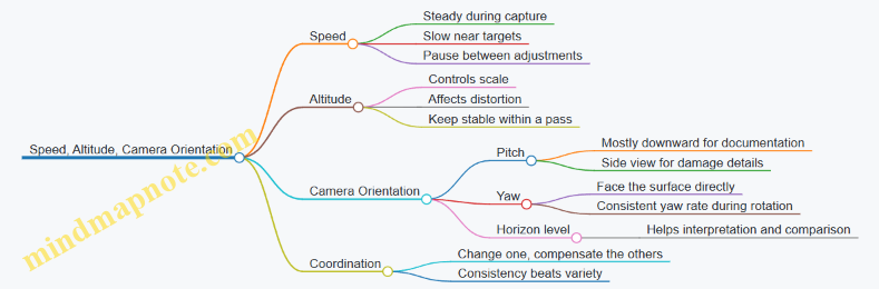
Micro-Checks Before You Commit to a Pass
Do quick checks that cost seconds and save hours:
- Confirm the camera pitch matches your plan. If you intended downward but it’s angled, correct before starting the strip.
- Verify speed by watching ground movement in the preview. If the ground streaks, slow down.
- Check altitude stability by observing whether the target grows or shrinks during the shot.
Example: Roof Strip Capture Plan
- Set a mostly downward pitch.
- Choose an altitude that keeps the roof edge in frame with safe clearance.
- Fly a slow, steady segment along the strip.
- At the end, pause briefly, rotate to the next strip direction, and repeat.
- Switch to a side-facing orientation only when you need seam-level detail.
This sequence keeps geometry consistent, so your later review is about findings, not guessing why the images look different.
10.2 Using Waypoints and Grid Patterns for Coverage
Coverage is what turns “I flew around” into “I captured the whole area.” Waypoints and grid patterns help you repeat the same path, keep overlap consistent, and reduce the urge to improvise mid-flight. The goal is simple: plan a route that matches your task, then fly it with stable speed, altitude, and camera orientation.
Core Concepts for Waypoint Coverage
A waypoint is a GPS-defined point the drone will fly to, usually with a specified altitude and sometimes a camera action. A grid pattern is a structured set of parallel lines that sweeps the area in a predictable way. For roof inspection and thermal checks, predictable overlap matters more than fancy camera moves.
Start with three inputs: (1) the area boundary, (2) the altitude you can maintain safely, and (3) the camera’s effective field of view at that altitude. If you don’t know the field of view, use the drone’s live camera preview to estimate how much roof width fits in the frame, then plan overlap accordingly.
Choosing Between Waypoints and Grid Patterns
Use waypoint routes when you need to follow a shape: a driveway curve, a perimeter with corners, or a roof edge that changes direction. Use grid patterns when you want uniform coverage: a flat section of roof, a yard for fence inspection, or a consistent thermal sweep.
A practical rule: if the area has many corners and you care about specific edges, waypoint routes are easier. If the area is mostly rectangular and you care about completeness, grids win.
Planning Overlap and Spacing
Overlap is the percentage of image content shared between adjacent passes. Too little overlap creates gaps; too much overlap wastes battery and increases time in the air. A good starting point for visual inspection is around 70–80% front overlap and 60–70% side overlap, then adjust after a test flight.
Example: Suppose your camera frame covers about 2.0 meters across at your chosen altitude. If you target 65% side overlap, your line spacing should be roughly 2.0 × (1 − 0.65) = 0.7 meters. You can apply the same logic to front overlap by adjusting your speed or the waypoint spacing along each line.
Building a Grid Pattern Step by Step
- Define the boundary: Mark the corners of the area you want covered. Keep the boundary slightly inside the real edges so you don’t clip into trees, walls, or gutters.
- Set altitude: Choose a height that keeps the drone stable in wind and maintains enough detail. For close roof work, keep altitude low enough for readable textures, but high enough to avoid sudden obstacles.
- Set line direction: Align grid lines with the longest dimension of the area. This reduces sharp turns and keeps the camera orientation consistent.
- Set spacing: Use your estimated frame width and overlap target to compute line spacing.
- Set speed: Move slowly enough that the camera doesn’t blur, especially if the drone is compensating for wind.
- Plan camera behavior: Prefer consistent settings and a stable gimbal angle. If your app supports it, use a fixed camera pitch rather than letting it drift.
Waypoint Route Design for Corners and Edges
Waypoint routes shine when you need to “trace” important boundaries. For example, to inspect roof penetrations and flashing lines, you can place waypoints along the ridge, eaves, and around vents. Add extra points at corners so the drone slows or turns smoothly.
Example: For a small roof with a rectangular footprint, place waypoints at each corner and add two intermediate points on each long edge. This creates a gentle path that keeps the camera facing the roof surface instead of swinging during turns.
Mind Map: Coverage Planning Workflow
Example: Roof Coverage Grid with Practical Checks
Imagine a 6 m by 8 m roof section. You choose an altitude where the camera frame width is about 2.0 m. With 65% side overlap, line spacing is about 0.7 m, so you’ll need roughly 8 / 0.7 ≈ 12 lines. If each line is 6 m long, your total travel distance is about 12 × 6 = 72 m, plus turn distance.
Before committing, run a short test over one corner. Confirm that the image shows crisp shingle texture and that the next line overlaps without leaving a visible seam. If you see a seam, reduce spacing or slow down so the drone captures more consistent frames.
Common Failure Modes and Fixes
- Gaps between lines: Increase overlap by reducing spacing.
- Blurred images: Reduce speed and ensure the gimbal is not fighting sudden pitch changes.
- Uneven coverage near boundaries: Shrink the boundary inward slightly and add a buffer line if your app allows.
- Camera angle drift: Use a fixed pitch and avoid switching modes mid-route.
Quick Reference: What to Verify Before Pressing Start
Confirm boundary points are correct, altitude is safe, grid lines align with the longest dimension, overlap targets are reasonable for your frame size, and camera pitch is stable. Then fly the route once, review the images for gaps and sharpness, and adjust spacing or speed for the next run.
10.3 Managing Wind and Gusts for Stable Shots
Wind management is mostly about planning: you choose the shot geometry, then you choose the timing and technique that keep the drone’s motion predictable. Consumer drones can handle moderate wind, but gusts are the part that turns “steady” into “why is that roof edge blurry?”
Foundational Wind Concepts That Affect Image Quality
Wind speed is only half the story. Gusts are rapid changes in wind force and direction, and they create sudden lateral movement. That movement shows up as motion blur, frame drift, and inconsistent overlap between images.
A second factor is your drone’s control authority. If the drone is already working hard to hold position, a gust forces larger corrections. Those corrections can tilt the gimbal and shift the camera’s pointing, even if the drone’s altitude looks stable.
Finally, consider wind gradient. Wind is often stronger near the roofline, tree canopy, or along open sides of a house. If you fly a path that crosses these zones, the drone will feel different “push” at different points.
Preflight Wind Assessment with Practical Checks
Start with a simple rule: if you can feel wind tugging at your clothes, expect the drone to notice it too. Use three checks before you take off.
- Local feel and visual cues: watch flags, leaves, and dust lines. Gusty conditions look like repeated bursts rather than a steady drift.
- Wind direction relative to your planned path: if you’ll fly back and forth, aim to keep the wind mostly aligned with one axis so corrections are consistent.
- Trial hover: hover at your intended working height for 10–20 seconds. If the drone hunts or slides noticeably, postpone or reduce the complexity of the shot.
If you must proceed, choose a lower-risk task first, like a short test pass, then commit to the full coverage.
Shot Planning That Reduces Gust Impact
Stability improves when you reduce the number of things that can change at once.
- Prefer headwind or tailwind for straight segments: headwind often keeps ground track steadier, while tailwind can cause drift that you only notice after the fact.
- Use shorter legs: instead of one long traverse, fly multiple shorter segments with brief pauses to let the drone settle.
- Keep the camera angle consistent: if you tilt the gimbal to a steep angle, small drone motion becomes larger apparent motion in the frame.
- Plan overlap with wind in mind: gusts can shift position between frames, so slightly increase overlap when you’re near the edge of acceptable coverage.
A good mental model is “motion budget.” Every gust consumes part of the budget; you protect the budget by simplifying the path and keeping the camera behavior predictable.
Advanced Technique for Windy Conditions
When gusts are present, your goal is not to fight the wind continuously; it’s to avoid being surprised by it.
- Fly with smooth inputs: abrupt joystick changes can trigger aggressive corrections that amplify blur.
- Use a consistent speed: too slow can cause the drone to oscillate as it constantly re-centers; too fast can make it harder to keep framing.
- Pause to re-stabilize: after each segment, hold position briefly before capturing the next set.
- Avoid crossing the wind line mid-shot: if you see a boundary where trees or structures change airflow, wait until you’re on the desired side before you start the capture.
If you’re doing roof inspection, treat each roof plane like a separate “scene.” Capture one plane, then move to the next after the drone has settled.
Example: Roof Edge Coverage in Gusty Wind
You’re inspecting a two-story roof edge. The wind is moderate but clearly gusty.
- You stand upwind and observe leaves flicking in bursts.
- You hover at the working height for 15 seconds and notice a small sideways slide.
- You plan the first pass as a short headwind-aligned segment along the eave, then you pause.
- You capture a tight set of images with consistent gimbal angle.
- You reposition to the next roof plane using a brief transition, then repeat.
The result is fewer blurry frames and more consistent overlap because each capture happens after the drone has stopped “chasing” the gust.
Mind Map: Wind and Gust Management for Stable Shots
Quick Decision Rules for When to Adjust
If you see any of these, adjust immediately: noticeable sideways hunting during hover, repeated frame-to-frame drift, or gimbal wobble during capture. The fix is usually the same: shorten the segment, slow down slightly, re-align with the wind, and capture again after a brief stabilization hold.
10.4 Avoiding Common Framing Errors and Glare Problems
Good coverage is mostly about two things: keeping your subject inside the frame and keeping the camera from turning bright surfaces into white blobs. Framing errors and glare often look unrelated, but they share the same root cause: you’re fighting geometry—sun angle, camera angle, and lens perspective—while the drone tries to hold a stable hover.
Foundational Framing Rules That Prevent Most Mistakes
Start with a simple mental model: the camera sees a rectangle, and your job is to make that rectangle match the job. If you’re inspecting a roof edge, the rectangle should include the edge plus a small margin for context. If you’re documenting a gutter run, the rectangle should show the gutter and the adjacent fascia so you can tell where water would go.
Use these practical checks before you commit to a full pass:
- Check the horizon line early. A tilted horizon makes later stitching and comparisons harder. If your app shows a grid, keep the roof line parallel to the grid lines.
- Leave consistent margins. If you crop too tight on the first shot, you’ll keep cropping too tight on the rest. A small, consistent border makes later review faster.
- Avoid “edge clipping.” When a feature sits exactly at the frame boundary, the next frame often clips it. Move the subject inward by a little, especially for corners and valleys.
- Use overlap on purpose. Overlap isn’t just for mapping; it also rescues framing. If one frame clips a detail, the next frame usually saves it.
Glare Basics That Explain What You’re Seeing
Glare is light that reflects straight into the lens. It’s common on glossy shingles, metal flashing, wet surfaces, and even dusty glass. The fix is rarely “change the camera setting only.” You usually need to change the angle between the sun, the surface, and the camera.
A quick rule: if the surface looks mirror-like, expect glare. If it looks matte, you can often get away with minor angle changes.
Systematic Approach to Glare Control
- Identify the likely reflective surfaces. Flashing edges, chimney caps, and roof valleys are frequent culprits.
- Note the sun direction relative to your approach. If you’re photographing toward the sun, glare is more likely.
- Adjust camera angle before altitude. Lowering altitude changes framing more than it changes reflection. Tilting the gimbal changes reflection geometry.
- Shift your lateral position. A small sideways move can move the specular reflection off the lens.
- Change time of day only when needed. If you can’t adjust angles safely due to obstacles, waiting for a better sun angle is the cleanest option.
A concrete example: you’re photographing a metal vent flashing. In the first pass, the flashing becomes a bright white strip. Instead of flying higher, keep altitude similar and yaw slightly so the camera looks at the flashing from a different angle. If glare persists, lower the gimbal angle a few degrees and reframe so the flashing is still visible but not centered on the brightest reflection.
Common Framing Errors and How to Correct Them
- Error: Subject is centered but context is missing. Fix by widening the frame to include the nearest reference line, like the ridge edge or gutter fascia.
- Error: Corners are cut off. Fix by planning a slightly wider approach path and using overlap so one frame captures the corner fully.
- Error: Repeated “almost the same” shots. Fix by varying either camera angle or position each frame. If every shot is identical, you’re not collecting backup coverage.
- Error: Over-zooming or relying on digital crop. Fix by using the camera’s native field of view and moving the drone instead of cropping.
Mind Map: Framing and Glare Troubleshooting
Example Workflow for a Roof Edge Pass
Plan a short test segment first: fly to the start of the eave, capture 3–5 frames with the edge fully inside the frame, and check for glare on flashing and wet-looking areas. If glare appears, adjust gimbal angle and yaw position, then repeat the same segment. Once the test segment looks clean, continue the pass with the same framing margins and overlap.
Quick Checklist You Can Run Mid-Flight
- Is the feature fully inside the frame with a margin?
- Is the horizon level or intentionally aligned?
- Are reflective surfaces showing detail or turning white?
- If glare appears, did you change camera angle or lateral position first?
- Do you have overlap that would rescue a clipped corner?
When you treat framing and glare as geometry problems, the fixes become predictable. You stop guessing, and your shots start behaving like evidence instead of lottery tickets.
10.5 Capturing Close Range Detail Without Compromising Safety
Close-range detail is where consumer drones can be genuinely useful—roof edges, gutter lines, vent penetrations, and fence hardware all benefit from tighter framing. It’s also where risk concentrates: less reaction time, more chance of prop wash disturbance, and a higher likelihood of clipping something you didn’t notice. The goal is simple: get the detail you need while keeping your flight envelope forgiving.
Foundational Concepts for Safe Close Range
Start by treating “close range” as a change in operating mode, not just a camera setting. At short distances, small errors in position become large errors in framing and clearance. That means your workflow must prioritize three things: predictable control, stable camera behavior, and clear escape space.
Predictable control comes from slower movement and consistent orientation. Use gentle stick inputs, avoid sudden yaw, and keep the drone’s nose direction aligned with your planned path. If you’re moving sideways along a roofline, fly in a way that maintains the same relative angle to the surface rather than continuously re-aiming.
Stable camera behavior depends on exposure and focus consistency. If the scene has mixed brightness—sun on shingles and shade under eaves—use settings that reduce hunting. Lock exposure where your app allows, or keep the drone’s motion slow enough that the camera can settle between frames.
Clear escape space means you should never “work yourself into a corner.” Before you start the close pass, identify where the drone can back out vertically or laterally without crossing over people, vehicles, or fragile objects.
A Practical Close Range Workflow
- Choose a safe approach path. Fly to a position that gives you a view of the target area while still leaving room to back away. If you can’t retreat without passing near the target, you’re too close.
- Set a conservative altitude buffer. For tight inspection, keep enough height that a small drift won’t turn into contact. Think in terms of “prop clearance plus margin,” not just “looks close enough.”
- Use a two-pass method. First pass establishes framing and distance. Second pass captures the detail set. This avoids the common mistake of trying to both position and photograph perfectly in one go.
- Capture overlap intentionally. Move in small increments so each frame overlaps the previous one. Overlap helps you re-check details later without needing to re-fly dangerously close.
- Pause to let the image settle. After each micro-move, hold position briefly. This reduces motion blur and helps the camera stabilize exposure.
Mind Map: Close Range Safety and Image Quality
Examples That Make the Workflow Concrete
Example: Roof Vent and Flashing Check
- Approach from the yard side, not from directly above the roof edge.
- First pass: hover at a distance where you can see the entire vent and surrounding flashing.
- Second pass: move closer in two or three short steps, pausing after each step.
- If the image is soft, don’t immediately reduce distance; instead, slow the movement and re-hold. Softness often comes from motion or exposure settling, not only distance.
Example: Gutter Line and Downspout Connections
- Fly parallel to the gutter rather than angling sharply toward it. Parallel motion keeps the camera angle stable.
- Capture a short “ladder” sequence: three positions along the same line with overlap, then back out.
- Review on the spot. If you missed a joint, re-run the ladder with a slightly different lateral offset rather than pushing closer.
Example: Fence Hardware and Gate Hinges
- Keep the drone high enough that prop wash doesn’t stir loose debris toward the camera or create confusing motion in the scene.
- Use a consistent yaw angle so hinge details don’t appear distorted by changing perspective.
- Capture from two angles if needed: one straight-on for shape, one slightly offset for surface cracks.
Advanced Details That Prevent Common Failure Modes
- Don’t confuse “detail” with “proximity.” If you can’t keep the drone steady, the image will be noisy even at close distance. Better results often come from steadier control and better overlap.
- Watch for surface glare. Shiny materials can wash out. Adjust angle by changing your position slightly rather than rushing closer.
- Account for wind at low altitude. Close work amplifies drift. If the drone is fighting the air, increase altitude buffer and use the camera’s framing rather than pushing into the drift zone.
- Use micro-moves, not continuous sliding. Continuous motion increases blur and makes it harder to judge distance.
Close-range detail is a craft of restraint: you move slowly, keep an exit route, and capture in repeatable steps. When you do that, the images get sharper for reasons that have nothing to do with luck—and everything to do with control.
11. Post Processing, Reporting, and Evidence Management
11.1 Selecting the Right Files for Review and Sharing
Good drone work produces more than pretty pictures. It produces evidence that can be checked, compared, and understood by someone else—often under time pressure. The goal of this section is simple: pick the files that answer the questions your inspection, survey, patrol, or thermal check actually raised.
Start with the Question, Not the Folder
Before you touch file names, write down the decision you want to support. Examples:
- Roof inspection: “Which areas show likely water intrusion risk, and where exactly are they?”
- Land measurement: “Where are the boundary-relevant features, and how confident are the measurements?”
- Security patrol: “What happened at the gate at 02:10, and what evidence supports it?”
- Thermal checks: “Which surfaces show abnormal heat loss, and are they consistent across angles?”
This single sentence becomes your filter. If a file doesn’t help answer the question, it doesn’t make the review set.
Build a Review Set with a Three-Layer Filter
Use three layers so you don’t accidentally keep everything.
- Coverage layer: keep files that show the full area at the right scale.
- Example: For a roof, include at least one wide overview image per roof face plus the key valleys and penetrations.
- Detail layer: keep files that show the specific issue clearly.
- Example: If you suspect cracked flashing, keep the closest images where the crack edges are visible and in focus.
- Context layer: keep files that explain where the detail belongs.
- Example: Pair each close-up with a mid-range shot that includes a recognizable reference point like a vent, ridge line, or corner.
If you’re missing one layer, you may still share the detail, but you’ll likely confuse the reviewer.
Choose the Correct File Types for the Job
Different tasks need different file types. A practical approach:
- Visible inspection: keep JPEGs for quick review, plus the original capture if you need to re-check exposure.
- Thermal checks: keep the thermal image plus the matching visible frame if your workflow captures both.
- Survey and measurement: keep the images used for reconstruction and any exported outputs you generated from them.
- Patrol evidence: keep the clearest frames and the time-ordered sequence around the event.
If your drone app exports multiple versions, prefer the ones that preserve metadata and the highest usable resolution. “Highest” doesn’t mean “largest file.” It means “sharp enough to read what you need.”
Apply Naming Rules That Survive Sharing
When files travel, folder structure often gets lost. Use names that still make sense when they’re flattened.
A reliable pattern:
- Task-Location-Date-Sequence-Type
- Example:
Roof-BackSlope-2026-03-05-03-Detail.jpg
Keep sequence numbers consistent across the set. If you later add a recheck flight, continue the sequence rather than restarting.
Use a Simple Quality Checklist
Before you mark a file as “share-ready,” check these items:
- Focus: the key edges are crisp, not just “bright.”
- Exposure: highlights aren’t blown out where cracks or stains should be visible.
- Angle: the subject isn’t distorted beyond recognition.
- Stability: no obvious motion blur.
- Relevance: the file supports a specific claim you intend to make.
Example: A roof overview shot that’s sharp but too far away to identify flashing damage is still useful for context, but it shouldn’t be the only evidence for the claim.
Mind Map: Selecting Files for Review and Sharing
Create a Sharing Package That Matches the Audience
A clean package reduces back-and-forth.
- Review set folder: the smallest set that answers the question.
- Evidence folder: supporting files in case someone challenges a detail.
- Notes file: a short list mapping claims to filenames.
Example notes entry:
- “Possible flashing separation at valley near vent. See
Roof-BackSlope-2026-03-05-07-Detail.jpgand contextRoof-BackSlope-2026-03-05-05-Context.jpg.”
This keeps the reviewer from playing detective with your entire memory card.
Common Mistakes to Avoid
- Sharing only close-ups without context.
- Keeping multiple near-duplicates while discarding the one sharp frame.
- Naming files by “IMG_1234” and hoping the folder will survive.
- Mixing thermal and visible sets without indicating which is which.
A good review set is small, checkable, and consistent. If someone can understand it without asking you to explain your entire flight path, you picked the right files.
11.2 Organizing Folders for Roof, Survey, Patrol, and Thermal Sets
Good folder organization is less about neatness and more about retrieval speed when you need answers. When you return from a flight, you should be able to find the exact images used for a specific decision—roof leak call, boundary check, patrol incident, or thermal comparison—without guessing.
Core Folder Principles
Start with a single top-level structure that mirrors your real-world use. Keep each flight’s outputs together, and keep each task type separate enough that you can browse quickly.
Use a consistent naming pattern for folders and files:
- Date: use YYYY-MM-DD.
- Task: Roof, Survey, Patrol, Thermal.
- Location or Asset: short and recognizable, like “NorthRoof” or “BackFence.”
- Run: add “_01”, “_02” if you repeat the same task.
Example folder name: 2026-03-05_Roof_NorthRoof_01.
Mind Map: Folder Strategy
Recommended Directory Layout
Create one folder per task type under each date, then subdivide by purpose. This keeps browsing fast while preventing “everything everywhere” folders.
A practical layout:
01_Raw_Imports/2026-03-05_Roof_NorthRoof_01/2026-03-05_Survey_BackYard_01/2026-03-05_Patrol_DrivewayGate_01/2026-03-05_Thermal_GarageWall_01/
02_Processed_Exports/...same folder names...
03_Reports_Notes/...same folder names...
Inside each task folder, use the same subfolders every time:
Media_Original/Media_Exports/Annotations/Checklist/
Task-Specific Subfolders and What Goes Where
Roof Sets
Put images that show the roof surface and the “context shots” in separate subfolders. Context shots help you remember where the close-ups belong.
Media_Original/: all camera files as imported.Media_Exports/: cropped close-ups and stitched views.Annotations/: a short note file listing suspected issues and where they appear.Checklist/: a quick list of what you captured (eaves, valleys, penetrations).
Example: If you suspect a flashing gap, store the wide shot that includes the flashing plus the close-up crop in the same roof set folder. That way, a reviewer sees both the location and the detail.
Survey Sets
Keep ground control and image overlap together. If you later re-run processing, you want the original inputs and the exact output settings.
Media_Original/: raw images.Media_Exports/: orthomosaic or point cloud outputs.Annotations/: notes on control points used and any ground measurements.Checklist/: overlap and coverage notes, like “two passes, ~80% overlap.”
Example: If a boundary question depends on a corner marker, include a photo of the marker and the surrounding reference area in the same survey set.
Patrol Sets
Patrol folders should separate routine coverage from incident evidence. That reduces the chance you share the wrong material.
Media_Original/: all patrol media.Media_Exports/: selected stills or short clips.Annotations/: incident summary with time window and what changed.Checklist/: route notes and lighting conditions.
Example: If you notice a gate left open, keep the “before” and “after” frames in the same patrol set and write the approximate time range in Annotations/.
Thermal Sets
Thermal comparisons rely on scene setup. Store the “why it looks like that” context alongside the thermal frames.
Media_Original/: thermal frames and visible reference images.Media_Exports/: color-mapped thermal images and any overlays.Annotations/: emissivity notes, distance/angle notes, and what you compared.Checklist/: weather and timing notes relevant to the comparison.
Example: If you compare “before cleaning” vs “after cleaning,” create two thermal sets with the same asset name and run number, then reference both in a single note file under the later set.
Retrieval Workflow That Actually Works
When you need a specific answer, follow this order:
- Find the date folder.
- Select the task folder matching the decision type.
- Open
03_Reports_Notes/for the matching set name. - If the report references images, jump to
01_Raw_Imports/and open the same set.
This workflow prevents the common failure mode: you find a report but not the exact images that supported it.
Simple Example: One Day, Four Uses
On the same day, you might fly roof inspection, a quick yard survey, a perimeter check, and a thermal wall scan. Use four task folders under the same date, each with the same internal subfolders. That keeps your day’s work searchable without mixing evidence types.
Example set names:
2026-03-05_Roof_NorthRoof_012026-03-05_Survey_BackYard_012026-03-05_Patrol_DrivewayGate_012026-03-05_Thermal_GarageWall_01
11.3 Annotating Findings With Measurements and Reference Notes
Good annotations turn a folder of photos into a usable record. The goal is simple: anyone reviewing your work later should understand what you saw, where you saw it, how you measured it, and what you concluded—without guessing.
Foundational Annotation Rules
Start with a consistent template for every flight session. Use the same order each time: location context, capture method, measurement basis, and interpretation. If you skip one element once, you’ll end up re-checking the same roof valley or fence corner twice.
Use three layers of notes:
- Reference notes identify the “where” and “when” (e.g., roof face, compass direction, distance from a landmark).
- Measurement notes explain the “how” (e.g., camera settings, estimated scale method, reference object used).
- Finding notes state the “what” and “so what” (e.g., cracked shingle edge, likely water entry point, recommended recheck angle).
Keep your language specific. Instead of “damage present,” write “missing granule strip on north-facing shingle row, 3–5 cm wide, near flashing edge.” That level of detail makes later verification faster.
A Practical Annotation Template
For each finding, record:
- Finding ID: A short code like R1, S2, or T3.
- Location: “Front eave, left of downspout, ~1 m from corner.”
- Capture details: “Oblique photo at ~2.5 m AGL, gimbal pitched down 20°, 1/1000s.”
- Measurement basis: “Scale from known downspout width (approx. 10 cm) in same frame.”
- Evidence: “Primary image: IMG_0421; supporting image: IMG_0424.”
- Interpretation: “Granule loss suggests aging; recheck for lifted edges.”
- Action: “If lifted edge visible from ground, schedule repair; otherwise monitor at next inspection.”
If you cannot measure precisely, say so. “Estimated” is fine when you also explain the reference used.
Mind Map: Annotation Workflow
Annotation Workflow Mind Map
Systematic Example: Roof Inspection Finding
Finding: suspected flashing gap near a vent.
- Finding ID: R1
- Location: “South roof plane, right side of vent stack, ~0.8 m from vent base.”
- Capture details: “Photo captured during slow pass; gimbal angled to keep flashing edge sharp; shutter fast enough to reduce blur.”
- Measurement basis: “Gap width estimated using vent stack diameter as scale reference in the same frame.”
- Evidence: “IMG_0421 (primary), IMG_0424 (supporting).”
- Interpretation: “Dark line consistent with separation along flashing edge; could indicate water path.”
- Action: “Recheck from a lower oblique angle to confirm edge lift; if confirmed, note for contractor.”
Notice what’s missing: you didn’t claim a cause. You described what you saw and what would verify the interpretation.
Systematic Example: Survey-Style Measurement Note
Finding: fence corner alignment discrepancy.
- Finding ID: S2
- Location: “Back property line, near gate hinge post.”
- Capture details: “Overlapping images with consistent camera orientation; captured from a stable hover at a repeatable height.”
- Measurement basis: “Measured relative position using the same corner post as reference across frames; compared against a ground tape check.”
- Evidence: “IMG_1103 (overview), IMG_1107 (corner close-up).”
- Interpretation: “Apparent offset of ~15 cm compared to ground check; likely caused by perspective in the overview frame.”
- Action: “Use close-up frames for final measurement; record ground check value as the authoritative number.”
This is how you prevent “pretty maps” from overriding real-world checks.
Reference Notes That Save Time Later
Use repeatable location language. For example, “front eave, left of downspout” is better than “near the corner.” If you have multiple similar areas, add a segment label: “Segment A: between downspout and gutter bend.”
Also record lighting conditions when they matter. Glare can hide cracks, and shadows can exaggerate texture. A short note like “sun angle caused glare on shingles” explains why a later reviewer might see a different result.
Mind Map: Finding Confidence and Recheck Triggers
Finding Confidence Mind Map
Practical Formatting for Evidence Linking
When you annotate, always connect the note to filenames. If you later export or rename files, keep a stable mapping in your notes. A reviewer should be able to jump from “R1” to the exact primary image in seconds.
Finally, keep the “action” field short and concrete. “Recheck” is not an action; “recheck from lower oblique angle, capture flashing edge close-up” is.
11.4 Exporting Reports for Contractors and Household Records
Exporting is where your flight work turns into something a person can actually use. The goal is simple: produce files that are readable, consistent, and complete enough that someone else can review your findings without guessing what you meant.
Define the Report Audience and Purpose
Start by choosing what the export must accomplish.
- Contractor review: they need clear roof areas, problem locations, and a short explanation of what you observed.
- Household record: you need traceability, so you can compare later inspections and remember what changed.
A practical rule: if the export will be shared, include enough context to stand alone. If it’s for your own records, prioritize organization and repeatability.
Choose the Right Output Types
Use a small set of export formats so recipients aren’t forced to hunt for tools.
- PDF report: best for summaries, annotated images, and signatures.
- Image exports: keep originals plus a “review” set resized for quick viewing.
- Data exports: include measurement notes, flight logs, and any generated overlays.
Example: For a roof inspection, export a PDF with labeled photo sets, then include a folder of the original images named by area. If you used measurements, add a short table inside the PDF and keep the raw notes in a companion file.
Build a Consistent File Naming Scheme
Consistency prevents the classic “which one is the right version?” problem.
Use a pattern like:
YYYY-MM-DD_Task_Area_Version- Example:
2026-03-05_Roof_Valley_A_v1
Keep versions explicit. If you re-export after correcting labels, increment to v2 rather than overwriting silently.
Create a Contractor-Ready PDF Summary
A contractor PDF should be short enough to read in one sitting, but structured enough to act on.
Include these elements in order:
- Header: date, location description, drone model, and what was captured.
- Coverage overview: which roof sections were photographed.
- Findings: each issue gets a label, a photo set, and a plain-language note.
- Evidence: include at least one wider shot and one close detail for each issue.
- Limitations: mention anything that affected clarity, like glare or distance.
Witty but useful detail: if you can’t explain a finding in one sentence, the export is missing the key context.
Package Media and Notes for Household Records
For your own records, the export should support future comparison.
- Keep original images in an
Originalsfolder. - Keep review images in a
Reviewfolder with consistent resizing. - Store notes in a
Notesfolder using a single template. - Store exports in an
Exportsfolder with the PDF and any data files.
Example folder layout:
2026-03-05_Roof_Valley_A_v2/Originals/Review/Notes/Exports/
Add Annotations Without Making Them Confusing
Annotations should point, not decorate.
- Use labels that match your PDF findings list.
- Keep arrows or boxes consistent in style.
- Avoid stacking multiple labels on the same image unless the image is a true “map.”
If you need many labels, split into multiple images rather than cramming everything into one.
Include Traceability and Basic Metadata
Even if the recipient doesn’t care about technical details, traceability helps everyone.
Add:
- capture date
- approximate location description
- task type (roof inspection, thermal check, etc.)
- any known constraints (windy session, partial coverage)
If you used thermal checks, include the camera settings you relied on for interpretation, plus a note about ambient conditions if they affected contrast.
Mind Map: Exporting Reports
Example Export Package for a Roof Issue
You find a suspected valley leak.
- PDF includes: a coverage overview, then one finding labeled
Valley Leak Suspected, with two images (wide context and close detail) and a one-sentence observation. - Notes file includes: where the issue appears, what you could see, and what you couldn’t confirm.
- Folder includes:
Originalsfor the two images,Reviewresized versions, andExportswith the PDF.
The result is that a contractor can quote and plan work, while you can later verify whether the repair actually addressed the same spot.
11.5 Secure Storage and Access Control for Sensitive Media
Roof inspections, thermal checks, and security patrol footage often contain more than “pretty pictures.” They can reveal home layouts, occupancy patterns, vehicle details, and personal routines. Secure storage is mainly about controlling three things: where files live, who can access them, and how long copies persist.
Classify Media by Sensitivity
Start by tagging each capture set into one of three buckets:
- Routine documentation: general roof condition photos with no identifiable faces or license plates.
- Home layout and condition: close roof angles, interior-adjacent views, measurements, and any annotated findings.
- Privacy-sensitive: thermal images showing activity patterns, patrol footage, identifiable people, or readable identifiers.
Example: A daytime roof sweep is “Home layout and condition.” A night thermal pass over a driveway becomes “Privacy-sensitive,” even if you never record audio.
Use a Predictable Folder Structure
Security improves when you can’t accidentally dump everything into one folder. Use a structure that mirrors your workflow:
- Project (Roof, Survey, Patrol, Thermal)
- Date (use a consistent format like YYYY-MM-DD)
- Capture type (Photos, Video, Thermal, Notes)
- Access level (Public, Restricted, Private)
Example: Thermal/2026-03-05/Photos/Restricted/ keeps thermal stills separate from general notes.
Apply Encryption for At-Rest Storage
If your storage device is lost, encryption is what keeps the contents from becoming instant “neighborhood viewing.” Use full-disk encryption for laptops and encrypted containers for removable drives. Keep encryption keys protected by strong authentication, not by “I’ll remember it.”
Practical example: Store patrol footage on an encrypted external drive. Keep the drive disconnected when not in use, and only connect it during transfer and review.
Control Access with Least Privilege
Access control is less about locking everything down and more about granting only what’s needed.
- Owner: can decrypt, edit, and delete.
- Reviewer: can view and export reports but cannot alter originals.
- Household collaborator: can access only the specific project folder needed for repairs.
Example: If a contractor needs roof photos, export a report package from the restricted folder and share only that package, not the entire archive.
Separate Originals from Working Copies
Working copies are where people make changes, rename files, and accidentally create duplicates. Keep originals read-only and store edits in a separate “Working” area.
Example: After importing thermal images, keep originals in Private/Originals/ and do edits in Private/Working/. If something goes wrong, you still have the untouched source.
Manage Sharing with Time-Limited Packages
When you share, share a package that contains only what the recipient needs.
- Include a short manifest: what’s inside and what it represents.
- Strip unnecessary files like raw thumbnails or unrelated clips.
- Use a dedicated share folder that you delete after the task is complete.
Example: For a gutter cleaning job, share only the relevant exterior roofline images and a single annotated PDF. Don’t include the entire patrol set.
Keep an Audit Trail for Sensitive Projects
A simple log prevents “who moved what” confusion.
- Record import date, device used, and destination folder.
- Record who exported or shared a package.
- Record deletion events for temporary copies.
Example log entry: “2026-03-05 import from SD card to Thermal/2026-03-05/Photos/Restricted; exported contractor package on 2026-03-07; deleted working duplicates on 2026-03-08.”
Retention Rules and Secure Deletion
Not every file needs to live forever. Define retention by sensitivity:
- Routine documentation: keep until the project is closed.
- Home layout and condition: keep longer, but remove intermediate duplicates.
- Privacy-sensitive: keep only what you need for reports and evidence; delete raw patrol clips after they’ve served their purpose.
Secure deletion means overwriting or using secure erase features where supported. If you can’t guarantee secure erase, treat the device as sensitive and keep it encrypted until you can wipe it properly.
Mind Map: Secure Storage and Access Control
Example: A Complete Transfer and Share Workflow
- Import from the drone card into
Thermal/2026-03-05/Photos/Restricted/Originals/. - Copy only the selected images into
Thermal/2026-03-05/Photos/Restricted/Working/for annotation. - Export a contractor package containing only the annotated images and a short PDF summary.
- Share the package from a temporary folder, then delete that folder after the contractor confirms receipt.
- Remove the SD card contents after verifying the import log entry matches the destination.
This workflow keeps sensitive originals protected, limits what leaves your control, and makes it easy to answer basic questions later: what was shared, when, and with whom.
12. Maintenance, Troubleshooting, and Practical Operating Limits
12.1 Routine Maintenance for Motors, Props, and Airframe Integrity
Routine maintenance is less about “perfect condition” and more about catching small problems before they become expensive ones. For consumer UAVs, the usual failure chain starts with vibration, then heat, then degraded control response. Your job is to interrupt that chain early.
Foundations of What You Inspect and Why
Start with a simple rule: inspect before flight, verify after flight, and clean only what you can reach safely.
- Motors: Look for uneven wear, unusual noise, and signs of overheating. Motors that run hot often do so because of friction, misalignment, or prop damage.
- Props: Treat propellers as consumables. Nicks, bends, and hairline cracks can cause vibration that stresses bearings and the airframe.
- Airframe: Check for cracks, loose mounts, and impact marks. Even minor damage can shift alignment and make calibration less reliable.
Preflight Motor Checks That Take Two Minutes
Spin the props by powering on and using the drone’s motor test mode if your model supports it. If not, do a careful manual inspection without forcing anything.
- Visual condition: Confirm motor housings are clean and free of debris. Look for discoloration near the motor arms or mounts.
- Mount security: Gently check that motor arms feel firm. If you feel play, stop and investigate.
- Sound and smoothness: During a motor test, listen for grinding, clicking, or a “rough” tone. Smooth motors sound steady, not gritty.
Example: After a roof inspection session, you notice a slightly higher-pitched whine on one motor during the test. You also find a prop with a small leading-edge nick. Replacing the prop often resolves the noise because the motor no longer fights extra vibration.
Propeller Care That Prevents Vibration
Props are the most common maintenance item because they take the hits you don’t always notice.
- Replace after impacts: If a prop touched a wall, tree branch, or even a hard surface during landing, replace it.
- Replace after cracks or bends: A bent prop may still spin, but it will shake.
- Check for imbalance: If one prop looks slightly different in shape or has uneven wear, swap it.
Example: You see a faint crack near a prop blade root. The crack might not be obvious in flight footage, but it can show up as “micro-jitters” in hover. Replacing the prop is faster than troubleshooting flight stability.
Airframe Integrity Checks That Matter for Alignment
Airframe checks focus on anything that can change geometry.
- Arms and landing gear: Look for cracks around screw holes and stress points.
- Mounts and brackets: Confirm camera and sensor mounts are secure and not loose.
- Gimbal and cable routing: Ensure cables are not pinched and that the gimbal moves without scraping.
- Fasteners: Verify screws are seated. If your drone uses thread-locking screws, don’t over-tighten.
Example: After a slightly rough landing on gravel, you find a scuff on an arm and a tiny gap around a mounting screw. Tightening the screw and checking the prop condition can restore stability, but if the arm is cracked, you should stop and replace the damaged part.
Cleaning and Handling Without Creating New Problems
Cleaning should remove debris without damaging coatings or seals.
- Before cleaning: Power down and remove the battery.
- Use the right tools: Soft brush for dust, microfiber for smudges, and dry methods first.
- Avoid soaking: Do not flood motor housings or electronics.
Example: After a dusty yard task, you brush off grit from motor arms and prop hubs. You avoid spraying cleaner into the motor area, which prevents residue from affecting cooling.
Postflight Verification That Closes the Loop
After flight, do a quick scan while the drone is still in your workflow.
- Heat check: If a motor feels noticeably hotter than the others, investigate props, debris, or binding.
- Prop wear pattern: Look for one prop wearing faster or showing uneven edges.
- Airframe marks: Confirm no new scuffs appeared that suggest a contact event.
Mind Map: Routine Maintenance Workflow
Practical Maintenance Routine You Can Actually Follow
Use a repeatable cadence:
- Every session: Visual motor check, prop inspection, and airframe scan.
- Every few sessions or after rough landings: More careful fastener and mount checks.
- After any contact event: Replace affected props and inspect the arm and mounts.
Example: You fly three short roof passes in one afternoon. After the first pass, you replace one prop due to a small nick. After the third pass, you notice a new scuff on an arm and a slightly loose mount. You tighten the mount, recheck the prop set, and confirm the gimbal moves freely before the next job.
Common Failure Patterns to Catch Early
- Vibration from damaged props: Shows up as jitter and uneven wear.
- Debris-induced motor strain: Shows up as heat and rough sound.
- Impact-related airframe cracks: Shows up as persistent instability even with new props.
Treat these as signals, not mysteries. If you change one variable at a time—prop first, then mounts, then airframe—you’ll keep maintenance systematic and your flights predictable.
12.2 Battery Care Practices for Longevity and Predictable Performance
Consumer drones usually run on Li-ion or LiPo packs, and they reward careful habits with consistent flight times and fewer “mystery” errors. Battery care is mostly about controlling three things: how full the pack sits, how hard it is worked, and how cleanly it is stored between flights.
Foundational Concepts That Drive Battery Behavior
A battery’s wear comes from stress. Stress increases when you store it at very high charge for long periods, when you repeatedly discharge it deeply, and when you subject it to high current draws (fast climbs, aggressive maneuvers, or heavy payloads). Heat is the multiplier: even if you never exceed the pack’s limits, repeated warm storage and hot landings accelerate aging.
A practical rule: aim for “moderate charge, moderate temperature, and moderate discharge depth.” That’s the boring formula that works.
Preflight Handling for Predictable Output
Start with a quick inspection. Look for swelling, cracked casing, loose balance leads, or a damaged connector. If anything looks off, treat the pack as retired from flight duty.
Next, check temperature. If the battery is cold from storage, let it warm to room temperature before takeoff. Cold packs can sag under load, which can trigger low-voltage warnings early even when the battery still has capacity.
Finally, use the correct charger and charge settings for your pack type. Mixing charger profiles or using an incompatible cable is a fast path to unreliable performance.
Charging Practices That Reduce Stress
Charge to the recommended level for your drone’s battery management system. For most consumer packs, that means charging to full only when you plan to fly soon.
If you won’t fly the same day, store at a mid-range charge level rather than leaving it full. A good target is roughly 40–60% state of charge for storage periods. This reduces chemical stress and lowers the chance of voltage drift.
Avoid charging immediately after a flight if the pack is hot. Let it cool to a safe, near-room temperature first. Charging a warm pack adds heat to heat, and that’s where aging speeds up.
Discharge Depth and Load Management
Try not to run the pack down to the point where the drone forces landing. Low-voltage cutoffs protect the battery, but repeated near-cutoff flights reduce capacity over time.
A simple habit: plan flights so you land with a buffer. For example, if your drone typically warns around a certain remaining percentage, treat that warning as “time to land,” not “time to keep going.”
Also manage current draw. If you need to climb or accelerate quickly, do it deliberately rather than repeatedly. Smooth control reduces peak current, which reduces heat and voltage sag.
Storage Routines Between Flights
Store batteries in a fire-resistant container or on a nonflammable surface, away from direct sunlight and drafts that can cause uneven heating. Keep them at a stable room temperature.
Before storage, check the pack’s condition and ensure it’s not left fully charged for extended periods. If you store multiple packs, label them with the last charge date and approximate state of charge so you can rotate them.
If you have a pack that sits unused for weeks, periodically check its voltage and recharge to the appropriate storage level rather than letting it drift to extremes.
Balance and Health Checks
Many packs include cell balancing. The charger handles balancing during charge, but you still need to start with correct settings and a healthy connection.
During routine use, watch for symptoms: sudden drops in runtime, inconsistent power delivery, or repeated low-voltage warnings at the same flight style. These patterns often indicate cell imbalance or capacity loss.
If your drone supports it, review battery health indicators after flights. Use them as a trend tool, not a single-day verdict.
Example Workflows for Common Scenarios
Example: Roof Inspection Morning
- Take the battery out of storage and let it reach room temperature.
- Charge to full only if you’ll fly within a short window.
- Fly at a steady pace, avoid repeated hard climbs.
- Land when the drone signals low battery, then cool the pack before charging again.
Example: Weekend Patrol With Two Batteries
- Charge both to full the night before.
- Use Battery A first, then Battery B.
- After the session, store both at a mid-range charge level for the next week.
- Rotate usage so neither pack always sits full or always sits near empty.
Mind Map: Battery Care Practices for Longevity
Quick Reference Checklist
- Inspect for physical damage every session.
- Warm cold packs before takeoff.
- Charge to full only when you’ll fly soon.
- Cool after flight before charging.
- Land with a buffer; don’t chase the last minutes.
- Store around mid charge for weeks.
- Watch for trends in runtime and warning behavior.
A well-cared battery doesn’t just last longer; it behaves more predictably, which makes planning roof shots, survey passes, and thermal checks far less stressful.
12.3 Troubleshooting GPS, Compass, and Sensor Errors
When a drone reports GPS or compass trouble, it’s tempting to keep flying “just to finish the shot.” Don’t. These errors often affect position hold, return-to-home behavior, and safe navigation around obstacles. The goal is simple: identify which sensor is unhappy, confirm whether the environment is the cause, then restore stable readings before you attempt any task.
Foundational Concepts for Sensor Reliability
GPS provides location; the compass provides heading; other sensors (IMU, barometer, vision aids) help the drone stay level and track motion. Many “GPS errors” are actually heading or interference problems that make the flight controller distrust its own position. A practical mindset helps: treat each message as a symptom, then test the most likely causes in a short, repeatable order.
Mind Map: Error Sources and Checks
Step 1: Identify the Message
Start by writing down the exact wording from the app. “GPS signal weak” usually points to satellite geometry or blockage. “Compass interference” points to magnetic disturbances. “Navigation accuracy” warnings can appear when GPS is weak or when heading is inconsistent.
Example: If you see “GPS signal weak” while standing beside a metal shed, then move 30–50 meters away and the warning disappears, you’ve learned something important: the issue was local blockage, not a broken GPS.
Step 2: Check Environment
Most compass problems come from nearby magnetic sources. Common culprits include cars, bicycles with steel frames, large speakers, toolboxes, and even some phone mounts with magnets. GPS issues often come from tall buildings, trees, and terrain that block line-of-sight.
Concrete detail: before calibration, do a “walk test.” Keep the drone powered but on the ground, then move yourself and the drone to a more open spot. If the compass warning clears without any calibration, you likely had interference rather than a faulty sensor.
Step 3: Check Hardware
If you recently had a hard landing, check for cracks around the sensor area and ensure nothing is loose. A bent frame can shift sensor alignment enough to trigger repeated heading problems. Also confirm you’re using the correct props and that they’re seated properly; vibration can worsen sensor stability.
Example: After replacing props, a user notices compass errors return immediately on startup. The likely cause is not the compass itself but vibration or a loose component. Tighten the prop fit, inspect for damage, then retest in a clean open area.
Step 4: Perform Controlled Tests
Use a short sequence so you don’t create new variables.
- Power cycle: Turn the drone off and back on, then wait for initial sensor checks.
- Satellite check: Look for a stable satellite count and reduced warning frequency.
- Compass calibration only when required: If the app requests calibration, follow its method exactly and avoid doing it near metal objects.
- Direction sanity check: After calibration, slowly rotate your body around the drone and confirm the heading indicator changes smoothly.
Example: A compass warning appears near a garage. You calibrate inside the garage and the warning persists. Move outside, calibrate again in open space, and the warning stops. The first calibration was “accurate,” but it was accurate for the wrong magnetic environment.
Step 5: Decide Go/No-Go
A reliable rule: if warnings reappear immediately after takeoff, treat it as a no-go for precise work like roof inspection or surveying. For simple tasks, you still need stable behavior: position hold should feel steady, and return-to-home should not trigger repeated navigation warnings.
Common Scenarios and Fixes
- GPS weak near the house: Move to an open yard or driveway corner with fewer obstructions; avoid flying under dense tree canopies.
- Compass interference near tools: Keep the drone and controller away from tool benches, vehicles, and magnetic accessories during calibration.
- Repeated navigation accuracy warnings: Recheck environment first, then inspect for recent impact damage.
- Sensor error after a crash: Stop troubleshooting and inspect the airframe thoroughly; vibrations and misalignment can keep the system unstable.
Quick Reference Mind Map for Decisions
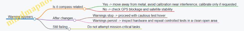
Practical Example Workflow for a Roof Inspection Day
You plan a roof inspection and start the drone on the driveway. The app shows “compass interference.” You step away from the garage door and metal railing, then the warning clears. You take off and hover briefly to confirm stable position hold. Only then do you begin the first roof pass, keeping the drone’s path away from the most obstructed areas so GPS remains consistent.
This approach keeps troubleshooting grounded: you change one factor at a time, you verify stability before you commit to work, and you treat sensor warnings as instructions rather than suggestions.
12.4 Handling App Crashes, File Corruption, and Media Recovery
When an app crashes mid-flight, the goal is not to “fix” the drone; it’s to preserve evidence and restore a working workflow. Consumer UAV apps typically manage three things separately: live telemetry, media capture, and local file storage. Crashes usually interrupt one or more of those streams, so the recovery steps should match the failure mode.
Foundations for Diagnosing What Broke
Start by separating symptoms into categories:
- Crash during flight: the app closes, but the drone may still have recorded to its storage.
- Crash after landing: the flight is done, but media transfer or indexing failed.
- Corrupted media: files exist but won’t preview, or thumbnails show as broken.
- Missing media: the flight log exists, but expected photos or videos are absent.
A simple rule helps: assume the drone recorded something until you confirm otherwise. Many drones write media to an internal card or onboard storage independent of the phone app.
Immediate Actions After a Crash
- Do not power-cycle repeatedly. If you suspect the app crashed while writing, multiple reboots can worsen file system damage.
- Keep the storage path unchanged. If the drone uses a microSD card, remove it only after the drone is fully powered down.
- Record what you saw. Note the time of the crash, approximate flight segment, and whether you were capturing photos, video, or thermal frames.
- Check the drone’s storage first. If the drone has an onboard card, connect it to a computer and inspect file presence before relying on the phone’s gallery.
Mind Map: Recovery Workflow
File Corruption: What It Looks Like and What to Do
Corruption usually shows up as one of these patterns:
- Video files won’t play or show a duration of zero.
- Photo thumbnails are blank or the app reports an unsupported format.
- Thermal frames appear incomplete, often when capture was interrupted.
Recovery steps should be conservative:
- Copy the entire storage to a working folder first. Recovery tools and re-indexing should operate on copies, not the original card.
- Check for partial writes. If you see a sequence where the last file is tiny compared to others, that last file may be incomplete.
- Try a different viewer, not a different assumption. If a file won’t preview in the app but opens in a basic media viewer, the file may be intact and the app’s indexing is the issue.
- If the card shows repeated errors, stop using it. A failing card can create “new” corruption during subsequent flights.
App Crashes: Restoring a Stable Capture Pipeline
After you recover what you can, focus on preventing repeat failures:
- Clear the app’s media cache if the app supports it, especially if thumbnails are stuck or transfers never finish.
- Re-check capture settings before the next flight: photo mode, video resolution, and whether thermal capture is enabled.
- Confirm storage capacity and free space. A nearly full card is a common reason for interrupted writes.
- Reduce background load on the phone. Close heavy apps and disable aggressive battery optimization for the drone app.
Example: Crash During Roof Coverage
You’re running a planned roof route and the app closes at the moment you switch from photos to video. After landing, you find the phone gallery has nothing from that segment.
- You power down the drone, remove the microSD, and inspect it on a computer.
- You find photo files from earlier segments and a set of video files near the crash time.
- One video file is much smaller than the rest; you treat it as likely incomplete and rely on the photos plus the last intact video.
- You then reconfigure the next flight to keep capture mode consistent for each pass, reducing the chance of mode-switch interruptions.
Example: Corrupted Files After a Successful Flight
The flight log looks normal, and the drone was stable, but the app shows broken thumbnails.
- You copy the card to a folder named with the flight date and time.
- You open the copied files with a basic media viewer; most photos display correctly.
- The issue is app indexing rather than storage damage, so you re-import or re-index within the app and then proceed with your inspection report.
Practical Checklist for the Next Flight
- Confirm onboard storage files exist before trusting phone transfers.
- Copy recovered media to a working folder and leave originals untouched.
- Validate card health if corruption repeats.
- Run a short test capture after app recovery to confirm stable writing.
- Document the failure mode so your next troubleshooting is targeted, not random.
12.5 Defining Safe Operating Limits for Your Equipment and Conditions
Safe operating limits are not a single number; they’re a set of boundaries that keep your drone controllable, your data usable, and your risk predictable. The goal is simple: decide what you will not do, before you’re stressed, tired, or low on battery.
Foundational Limits You Can Measure
Start with limits that are directly tied to your hardware.
- Battery and power margin: Use a conservative “return point” rule. For example, if your typical task takes 12 minutes and you have a 30-minute battery rating, plan to start landing at the point where you still have enough power for a normal return plus a safety buffer. If your drone often lands early in cold weather, treat cold as a battery limit multiplier.
- Wind capability: Your drone may tolerate a certain wind in calm conditions, but gusts are the real problem. If you see repeated heading drift or you need constant stick correction, you’ve reached your practical wind limit even if the app hasn’t declared an error.
- GNSS and sensor reliability: GPS-denied areas, heavy tree cover, or reflective surfaces can degrade position holding. If the drone oscillates or “hunts” for stability, reduce speed, increase altitude if safe, or stop the mission.
- Camera and gimbal constraints: Limits here are about image quality and safe proximity. If you’re flying close to roofs or walls, keep enough clearance to avoid rotor wash effects and to prevent the camera from being blocked by the frame or landing gear.
Condition Limits That Change Day to Day
Next, define limits based on the environment.
- Lighting: Thermal checks and visible inspection both suffer when contrast is misleading. If the sun is low and glare washes out roof surfaces, switch to a different angle or time window rather than forcing the shot.
- Precipitation and moisture: Light mist can still affect electronics and prop performance. If you notice condensation risk or wet propellers, treat it as a “do not fly” condition.
- Surface hazards: Dust, loose gravel, and tall grass can be sucked into intakes or reduce control during takeoff and landing. Choose a takeoff spot that stays stable and clear.
- People and property density: Even if the drone is technically capable, crowded areas reduce your acceptable risk. A quiet field and a busy driveway are different operating environments.
A Practical Decision Ladder
Use a step-by-step go/no-go process so you’re not improvising mid-flight.
- Preflight check: Confirm firmware status, compass health, and battery condition. If any sensor warning appears, do not “try anyway.”
- Dry run the workflow: Practice the takeoff, hover, and landing sequence on a calm day. If you can’t land smoothly when you’re not rushed, you won’t magically land smoothly during a real task.
- Set your abort triggers: Choose clear triggers such as “battery reaches return threshold,” “wind causes repeated drift,” “video feed stutters beyond a short moment,” or “position holding becomes unstable.”
- Start conservative: First flight should be the easiest version of the mission. If it behaves well, you can repeat with the same settings.
- Stop early: If you’re collecting evidence for a roof or survey, missing one segment is better than forcing the last segment and losing the whole set.
Example: You plan a roof inspection. The wind is steady, but gusts begin to push the drone sideways during a slow pass. Your abort trigger is “repeated heading correction for more than 10 seconds.” You stop the pass, land, and reschedule rather than trying to “power through” and ending up with blurred images.
Mind Map: Safe Operating Limits
Turning Limits into Numbers Without Overconfidence
You can translate the ladder into simple rules you can remember.
- Battery rule: “I start landing when I hit my return threshold, not when I feel like it.”
- Wind rule: “If I’m correcting constantly, I’m done.”
- Stability rule: “If it hunts, I stop and reassess.”
- Data rule: “If images are blurry or incomplete, I redo the segment only when conditions improve.”
Example: During a thermal check, the drone’s thermal view looks fine, but the visible camera feed stutters. You treat the stutter as a link/processing limit, land, and restart rather than continuing and risking mismatched time stamps between thermal and visible sets.
Documenting Your Personal Limits
Finally, record what worked. After each flight, note battery behavior, wind feel, stability quality, and whether the images met your standard. Over time, you’ll have a practical boundary map for your specific drone, your typical locations, and your own comfort level—without pretending the world is consistent.