Precision Motion Control And Machine Vision Coordination In High Throughput Robotic Cells
1. Introduction to High Throughput Robotic Cells
1.1 Overview of High Throughput Manufacturing Environments
High throughput manufacturing environments are designed to maximize production speed while maintaining quality and precision. These environments are characterized by rapid processing cycles, minimal downtime, and seamless integration of automation technologies such as robotics, motion control, and machine vision.
Key Characteristics of High Throughput Manufacturing:
- Speed: Processes are optimized to achieve the highest possible output per unit time.
- Precision: Despite the speed, products must meet strict quality and dimensional tolerances.
- Automation: Extensive use of automated systems reduces human intervention and errors.
- Scalability: Systems are designed to handle varying production volumes efficiently.
- Flexibility: Ability to quickly adapt to different product types or changes in production requirements.
Mind Map: Core Elements of High Throughput Manufacturing Environments
Importance of High Throughput in Industrial Robotics
Incorporating robotics into high throughput environments enables:
- Consistent and repeatable operations: Robots perform tasks with high accuracy, reducing variability.
- Increased uptime: Automated cells can operate continuously with minimal breaks.
- Enhanced safety: Robots handle hazardous or repetitive tasks, protecting human workers.
Example: Automotive Assembly Line
An automotive assembly line is a classic example of a high throughput manufacturing environment. Robots perform welding, painting, and assembly tasks in a tightly choreographed sequence. Precision motion control ensures that robotic arms position components accurately at high speeds, while machine vision systems inspect weld quality and alignment in real-time.
- Best Practice: Synchronize robot motion with conveyor speed and vision inspection to avoid bottlenecks.
Mind Map: Benefits of Robotics in High Throughput Manufacturing
Challenges in High Throughput Environments
- System integration complexity: Coordinating multiple robots, sensors, and controllers.
- Data management: Handling large volumes of vision and sensor data in real-time.
- Maintenance: Ensuring minimal downtime through predictive and preventive strategies.
Example: Electronics Manufacturing
In electronics manufacturing, high throughput cells assemble and test circuit boards. Machine vision inspects solder joints and component placement, while precision motion control handles delicate pick-and-place operations at high speed.
- Best Practice: Implement real-time feedback loops between vision systems and motion controllers to correct placement errors instantly.
By understanding the core elements and challenges of high throughput manufacturing environments, robotics engineers, controls engineers, and systems integrators can design and implement robotic cells that deliver both speed and precision, meeting the demanding requirements of modern industrial production.
1.2 Role of Robotic Cells in Industrial Automation
Robotic cells are fundamental building blocks in modern industrial automation, enabling manufacturers to achieve high throughput, precision, and flexibility. A robotic cell typically consists of one or more robots, end-effectors, sensors (including machine vision), and control systems working together in a defined workspace to perform specific tasks such as assembly, material handling, inspection, or packaging.
Key Roles of Robotic Cells in Industrial Automation
- Automation of Repetitive Tasks: Robotic cells take over repetitive, labor-intensive, or ergonomically challenging tasks, improving worker safety and reducing fatigue.
- Enhancement of Precision and Consistency: Robots operate with high repeatability and accuracy, minimizing variability and defects.
- Increased Throughput: By optimizing cycle times and enabling continuous operation, robotic cells boost production rates.
- Flexibility and Scalability: Modular robotic cells can be reprogrammed or expanded to accommodate new products or processes.
- Integration of Quality Control: Machine vision integrated within robotic cells enables real-time inspection and defect detection.
Mind Map: Core Functions of Robotic Cells
Example 1: Automotive Assembly Line
In an automotive manufacturing plant, robotic cells are deployed for tasks such as welding car body panels. Each cell contains multiple robotic arms programmed to perform precise welds. Machine vision systems inspect weld quality immediately after completion, providing feedback to adjust parameters in real-time. This integration ensures consistent quality and reduces rework.
Mind Map: Automotive Robotic Cell
Example 2: Electronics Manufacturing
In electronics production, robotic cells perform delicate tasks like PCB assembly and soldering. Precision motion control ensures accurate placement of tiny components, while vision systems verify component presence and orientation. This coordination reduces errors and supports high-speed production.
Mind Map: Electronics Manufacturing Robotic Cell
Best Practices for Leveraging Robotic Cells
- Design for Task Specificity: Tailor robotic cells to the specific task requirements to maximize efficiency.
- Integrate Vision Early: Incorporate machine vision at the design stage to enable real-time quality control.
- Ensure Robust Communication: Use reliable protocols for seamless coordination between robots, vision systems, and controllers.
- Plan for Flexibility: Design cells with modular components to adapt to product changes.
Summary
Robotic cells serve as the backbone of industrial automation by combining precision motion control and machine vision to automate complex tasks with high speed and accuracy. Their role spans from improving safety and quality to enabling scalable and flexible manufacturing processes, making them indispensable in modern production environments.
1.3 Importance of Precision Motion Control and Machine Vision
In high throughput robotic cells, precision motion control and machine vision are foundational technologies that enable automation systems to perform complex tasks with speed, accuracy, and reliability. Their importance cannot be overstated as they directly impact product quality, operational efficiency, and overall system flexibility.
Why Precision Motion Control Matters
Precision motion control ensures that robotic actuators move exactly as intended, following precise trajectories and positioning with minimal error. This capability is critical for tasks such as assembly, welding, material handling, and packaging where even minor deviations can cause defects or damage.
- Improved Product Quality: Accurate positioning reduces errors and inconsistencies.
- Increased Throughput: Precise and repeatable movements enable faster cycle times.
- Reduced Wear and Tear: Smooth, controlled motions extend equipment life.
Example: In an electronics assembly line, a robotic arm equipped with precision servo motors places tiny components on circuit boards. Even a 0.1 mm misalignment can cause faulty connections, so the motion control system must maintain sub-millimeter accuracy throughout thousands of cycles.
The Role of Machine Vision
Machine vision systems provide robots with the ability to “see” and interpret their environment. They capture images, analyze features, and provide feedback that guides robotic actions.
- Part Identification and Orientation: Vision systems detect and locate parts regardless of their initial position.
- Quality Inspection: Automated detection of defects, surface anomalies, or assembly errors.
- Adaptive Control: Vision feedback allows robots to adjust motions dynamically.
Example: In a high-speed packaging cell, a vision system scans incoming products to verify barcode readability and orientation. If a package is misaligned, the robot adjusts its grip and placement accordingly, preventing jams and errors.
Synergistic Importance of Coordinating Precision Motion Control with Machine Vision
When combined, precision motion control and machine vision create a powerful synergy that enables advanced automation capabilities:
- Closed-Loop Control: Vision feedback corrects motion errors in real time.
- Flexibility: Robots can handle variable parts and unpredictable conditions.
- Higher Accuracy: Vision-guided adjustments improve positioning beyond open-loop capabilities.
Mind Map: Importance of Precision Motion Control and Machine Vision
Best Practice: Integrate Vision Early in the Design Phase
Incorporating machine vision requirements early ensures that motion control systems are designed to leverage vision feedback effectively. For example, selecting motion controllers that support real-time communication with vision processors enables tight synchronization.
Example: A systems integrator designing a robotic cell for automotive part assembly integrates a high-speed camera and selects a motion controller with deterministic Ethernet communication. This setup allows the robot to adjust pick positions on-the-fly based on vision data, reducing scrap rates by 15%.
Summary
Precision motion control and machine vision are critical enablers of high throughput robotic cells. Their coordinated use leads to improved product quality, operational efficiency, and system adaptability. Understanding their importance helps engineers design robust, flexible automation solutions that meet demanding industrial requirements.
1.4 Key Challenges in Coordinating Motion Control with Vision Systems
Coordinating precision motion control with machine vision systems in high throughput robotic cells presents several critical challenges. Understanding these challenges is essential for robotics engineers, controls engineers, and systems integrators to design robust, efficient, and accurate automation solutions.
Challenge 1: Real-Time Data Processing and Latency
- Description: Machine vision systems generate large volumes of image data that must be processed quickly to provide timely feedback for motion control.
- Impact: Delays in image processing can cause motion commands to be outdated, leading to positioning errors or collisions.
Example: In a pick-and-place operation, if the vision system detects a part’s position but the motion controller receives this data too late, the robot may attempt to pick the part from an incorrect location, causing a failed pick or damage.
Mind Map:
Challenge 2: Synchronization Between Vision and Motion Systems
- Description: Coordinating the timing between when the vision system captures images and when the robot moves is critical to ensure accurate positioning.
- Impact: Poor synchronization can result in the robot acting on stale or incorrect data.
Example: A conveyor belt moves parts continuously; the vision system must capture images at precise moments aligned with the robot’s motion to correctly locate parts for picking.
Mind Map:
Challenge 3: Coordinate System Alignment and Calibration
- Description: The coordinate frames of the vision system and the robot must be precisely aligned to translate vision data into accurate motion commands.
- Impact: Misalignment leads to positioning errors and reduced accuracy.
Example: If the camera’s coordinate system is not properly calibrated with the robot’s base frame, the robot may pick parts offset from their actual location.
Mind Map:
Challenge 4: Environmental Variability
- Description: Changes in lighting, reflections, or part orientation can affect vision system accuracy.
- Impact: Inconsistent image quality leads to unreliable data for motion control.
Example: A glossy part under fluctuating lighting conditions may cause glare, confusing the vision system and resulting in incorrect position detection.
Mind Map:
Challenge 5: Communication and Integration Complexity
- Description: Integrating heterogeneous hardware and software components (robot controllers, vision processors, PLCs) requires seamless communication.
- Impact: Communication bottlenecks or incompatibilities can degrade system performance.
Example: A vision system using GigE Vision protocol must reliably communicate with a motion controller using EtherCAT without data loss or delays.
Mind Map:
Challenge 6: Handling Dynamic and Unpredictable Scenarios
- Description: Parts may vary in position, orientation, or presence, requiring adaptive coordination between vision and motion.
- Impact: Static programming fails; systems must dynamically adjust.
Example: In a bin picking application, parts are randomly oriented; the vision system must detect and communicate exact poses for the robot to grasp correctly.
Mind Map:
Summary
Coordinating precision motion control with machine vision in high throughput robotic cells involves overcoming challenges related to real-time processing, synchronization, calibration, environmental factors, communication, and dynamic variability. Addressing these challenges through best practices and thoughtful system design ensures robust and accurate automation.
Integrated Example: Vision-Guided Pick-and-Place Cell
Consider a robotic cell designed for high-speed pick-and-place of small electronic components:
- The vision system uses a high-speed camera with controlled lighting to capture images of parts on a moving conveyor.
- Real-time image processing algorithms detect part positions and orientations within milliseconds.
- Hardware triggers synchronize the camera capture with the conveyor position encoder to ensure timing alignment.
- Calibration routines align the camera coordinate system with the robot base frame, compensating for lens distortion.
- The motion controller receives vision data via a low-latency EtherCAT network and adjusts robot trajectories dynamically.
- Environmental sensors monitor lighting and trigger adjustments to maintain image quality.
This example embodies best practices addressing the key challenges discussed, resulting in a high throughput, precise, and reliable robotic cell.
1.5 Best Practices for Designing High Throughput Robotic Cells
Designing high throughput robotic cells requires a holistic approach that balances speed, precision, reliability, and maintainability. Below are best practices that robotics engineers, controls engineers, and systems integrators should consider to optimize performance and ensure seamless operation.
Modular and Scalable Design
- Modularity allows easy upgrades, maintenance, and reconfiguration without disrupting the entire system.
- Scalability ensures that the robotic cell can handle increased throughput demands by adding more robots or stations.
Example: A packaging line uses modular robotic arms with standardized end effectors. When demand increases, additional arms can be integrated with minimal reprogramming, maintaining throughput without major downtime.
Robust Communication and Synchronization
- Use real-time communication protocols (e.g., EtherCAT, PROFINET) to synchronize motion control and vision systems.
- Ensure low latency and deterministic data exchange to prevent bottlenecks.
Example: In a high-speed assembly cell, EtherCAT is used to synchronize the robot’s motion controller with the vision system, ensuring the robot picks parts only after the vision system confirms correct positioning.
Integrated Machine Vision for Feedback
- Embed vision systems directly into the robotic cell to provide real-time feedback for alignment, quality inspection, and error correction.
- Use vision-guided robotics to adapt to part variations and reduce rejects.
Example: A robotic cell assembling electronic components uses a 3D vision system to detect part orientation and adjust the robot’s pick position dynamically, improving assembly accuracy and throughput.
Optimize Cycle Time with Motion Profiling
- Use advanced motion profiles (e.g., S-curve, trapezoidal) to minimize acceleration/deceleration time without sacrificing precision.
- Coordinate multi-axis movements to reduce idle time.
Example: A pick-and-place robot uses S-curve acceleration profiles to reduce mechanical stress and achieve faster cycle times, increasing throughput by 15% without compromising accuracy.
Implement Redundancy and Fault Tolerance
- Design systems with redundant sensors and communication paths to avoid single points of failure.
- Use predictive maintenance algorithms to detect potential faults early.
Example: A robotic cell includes dual encoders on critical axes and backup network switches. When one encoder fails, the system automatically switches to the backup, maintaining operation without stopping the line.
User-Friendly HMI and Diagnostics
- Develop intuitive human-machine interfaces (HMI) for operators to monitor system status and quickly diagnose issues.
- Include visual indicators from both motion control and vision systems.
Example: An HMI dashboard displays robot positions, vision system pass/fail results, and cycle times. Operators can identify bottlenecks or faults immediately and take corrective action.
Environmental Considerations
- Control ambient lighting and temperature to ensure consistent vision system performance.
- Use vibration isolation to maintain precision in motion control.
Example: A robotic cell in a factory uses enclosed lighting with diffusers to eliminate shadows and glare, resulting in more reliable vision inspections and fewer false rejects.
Summary Mind Map
By following these best practices, engineers can design robotic cells that not only achieve high throughput but also maintain precision, flexibility, and reliability essential for modern industrial automation.
1.6 Example: A Case Study of a High-Speed Assembly Line
In this section, we explore a real-world example of a high-speed assembly line that leverages precision motion control and machine vision coordination to achieve remarkable throughput and quality. This case study highlights best practices and practical insights for robotics engineers, controls engineers, and systems integrators.
Overview of the Assembly Line
The assembly line is designed for manufacturing small electronic components, such as connectors and sensors, which require precise placement and inspection at high speeds. The robotic cell includes multiple articulated robots, conveyor systems, and machine vision stations.
Key Objectives:
- Achieve cycle times under 5 seconds per unit
- Maintain placement accuracy within ±0.05 mm
- Perform 100% quality inspection using machine vision
- Minimize downtime through automated calibration and monitoring
Mind Map: High-Speed Assembly Line Components and Workflow
Workflow Description:
- Part Feeding: Parts arrive on a high-speed conveyor with indexing tables to ensure precise positioning.
- Vision Identification: A machine vision camera captures images to identify part orientation and verify presence.
- Robot Pick-and-Place: Using vision feedback, the robot picks the part and places it onto the assembly fixture with high precision.
- Assembly Operation: Additional robots perform tasks such as screw driving or component insertion.
- Quality Inspection: Final machine vision stations inspect the assembled unit for defects, alignment, and completeness.
- Sorting and Packaging: Based on inspection results, parts are sorted for packaging or rework.
Best Practices Demonstrated:
-
Vision-Guided Robot Positioning: Using real-time vision data to correct robot trajectories, compensating for part placement variability.
-
Closed-Loop Motion Control: Employing servo motors with high-resolution encoders to maintain precise positioning and smooth motion.
-
Synchronized Triggering: Coordinating cameras and robot motion via hardware triggers to minimize latency and ensure image capture at exact moments.
-
Modular System Design: Separating vision and motion control modules for easier maintenance and scalability.
-
Automated Calibration: Periodic calibration routines executed during scheduled downtimes to maintain system accuracy.
Mind Map: Best Practices in the Case Study
Example: Vision-Guided Pick-and-Place
- Scenario: Parts on the conveyor may have slight positional deviations due to feeding inconsistencies.
- Solution: A camera captures the part position and orientation.
- Implementation: The vision system calculates the offset and sends correction data to the robot controller.
- Result: The robot adjusts its pick position dynamically, ensuring accurate grasp and placement.
This approach reduces rejects caused by misalignment and improves overall throughput.
Performance Outcomes:
- Cycle time consistently below 4.5 seconds per unit.
- Placement accuracy within ±0.03 mm, exceeding initial targets.
- 100% automated quality inspection with defect detection rate above 98%.
- Reduced downtime by 20% due to predictive maintenance and automated calibration.
Summary
This case study demonstrates how integrating precision motion control with machine vision in a high-speed robotic cell leads to significant improvements in throughput, accuracy, and quality. The use of synchronized systems, real-time feedback, and modular design principles are key enablers for success in modern industrial automation.
For robotics engineers and systems integrators, adopting these best practices and leveraging vision-guided control can transform high-throughput assembly lines into highly efficient, flexible manufacturing systems.
2. Fundamentals of Precision Motion Control
2.1 Principles of Motion Control in Robotics
Motion control is the backbone of robotic systems, enabling precise, repeatable, and coordinated movements essential for automation tasks. Understanding the fundamental principles of motion control helps engineers design robotic cells that meet high throughput and accuracy requirements.
What is Motion Control?
Motion control refers to the process of controlling the position, velocity, and acceleration of a mechanical system, typically a robot or actuator, to achieve desired movements.
Core Objectives of Motion Control in Robotics
- Precision: Achieving exact positioning and repeatability.
- Speed: Moving efficiently to maximize throughput.
- Smoothness: Avoiding jerky movements to reduce wear and improve accuracy.
- Synchronization: Coordinating multiple axes or robots.
Mind Map: Core Components of Motion Control
Open-Loop vs Closed-Loop Control
-
Open-Loop Control: Commands are sent to actuators without feedback. Simple but prone to errors due to disturbances or mechanical variations.
- Example: A stepper motor moving a fixed number of steps without position verification.
-
Closed-Loop Control: Uses feedback from sensors to correct errors in real time.
- Example: A servo motor with an encoder that continuously adjusts position to match the target.
Example: Open-Loop vs Closed-Loop in Pick-and-Place Robot
- In an open-loop system, the robot arm moves to a pre-programmed position assuming no external disturbances. If the object is slightly misplaced, the robot may miss the pick.
- In a closed-loop system, feedback from encoders and vision sensors allows the robot to adjust its position dynamically, ensuring accurate picking even if the object shifts.
Feedback Devices
- Encoders: Provide precise position and speed feedback by converting mechanical motion into electrical signals.
- Resolvers: Robust sensors used in harsh environments for angular position feedback.
- Other Sensors: Linear scales, tachometers, and accelerometers can provide additional data.
Control Algorithms
- PID Control (Proportional-Integral-Derivative): The most common control algorithm that adjusts actuator commands based on error, accumulated error, and rate of change of error.
- Feedforward Control: Predicts required actuator input based on desired trajectory, improving response time.
- Trajectory Planning: Generates smooth motion paths considering velocity and acceleration limits.
Mind Map: PID Control Components
Example: PID Control in a Robotic Joint
A robotic arm joint uses a PID controller to maintain its angle. If the joint deviates from the target angle due to load changes, the PID controller calculates the correction needed to bring it back smoothly and quickly.
Trajectory Planning
Trajectory planning ensures the robot moves along a path that respects mechanical constraints and optimizes cycle time.
- Point-to-Point Motion: Moves directly between two points.
- Continuous Path Motion: Follows a complex path smoothly.
Example: Trajectory Planning in Welding Robot
A welding robot follows a continuous curved path along a car body seam. The trajectory planner calculates velocity and acceleration profiles to maintain consistent weld quality without sudden speed changes.
Summary
Understanding the principles of motion control—including control types, feedback mechanisms, and control algorithms—is essential for designing robotic systems that deliver precision, speed, and reliability. Integrating these principles with real-world examples helps engineers implement effective solutions in high throughput robotic cells.
2.2 Types of Motion Control Systems: Servo, Stepper, and Linear Motors
In precision motion control for high throughput robotic cells, selecting the appropriate type of motor is crucial for achieving the desired accuracy, speed, and reliability. This section explores the three primary types of motion control motors used in industrial robotics: Servo motors, Stepper motors, and Linear motors. Each type has unique characteristics, advantages, and ideal application scenarios.
Servo Motors
Overview: Servo motors are rotary actuators that provide precise control of angular position, velocity, and acceleration. They use feedback devices such as encoders or resolvers to continuously monitor position and adjust accordingly.
Key Features:
- Closed-loop control system
- High torque-to-inertia ratio
- Smooth motion and high speed
- Excellent dynamic response
Best Practices:
- Use servo motors when high precision and dynamic performance are required.
- Pair with high-resolution encoders for improved accuracy.
- Implement PID tuning to optimize control response.
Example: A 6-axis articulated robot arm in an automotive assembly line uses servo motors to achieve smooth, precise movements for welding and part placement. The servo system compensates for load variations and maintains exact positioning.
Mind Map:
Stepper Motors
Overview: Stepper motors move in discrete steps, providing open-loop control of position without the need for feedback devices in many applications. They are simpler and cost-effective but generally less powerful and slower than servo motors.
Key Features:
- Open-loop or closed-loop operation
- High holding torque at standstill
- Simple control via pulse signals
- Limited speed and torque compared to servos
Best Practices:
- Use stepper motors for applications requiring moderate precision and low to medium speed.
- Employ microstepping to increase resolution and smoothness.
- Consider closed-loop stepper systems to reduce missed steps in demanding environments.
Example: A PCB assembly machine uses stepper motors for precise indexing of the conveyor and component feeders. Microstepping improves the smoothness of motion, reducing vibration and enhancing placement accuracy.
Mind Map:
Linear Motors
Overview: Linear motors produce direct linear motion without the need for rotary-to-linear mechanical conversion. They offer high acceleration and precision, ideal for applications requiring fast, accurate linear positioning.
Key Features:
- Direct drive linear motion
- High acceleration and speed
- Minimal mechanical backlash
- Requires linear feedback systems
Best Practices:
- Use linear motors where high throughput and precision linear motion are critical.
- Integrate with linear encoders for accurate position feedback.
- Design for thermal management due to heat generation at high speeds.
Example: A semiconductor wafer handling robot uses linear motors to rapidly and precisely position wafers along a linear axis, minimizing cycle time and maximizing throughput.
Mind Map:
Comparative Summary Table
| Feature | Servo Motor | Stepper Motor | Linear Motor |
|---|---|---|---|
| Control Type | Closed-loop | Open-loop (often) | Closed-loop |
| Positioning Accuracy | High | Moderate | Very High |
| Speed | High | Moderate | Very High |
| Torque Characteristics | High torque at speed | High holding torque at standstill | High thrust force |
| Complexity | Complex (requires tuning) | Simple | Complex |
| Cost | Higher | Lower | Higher |
| Typical Applications | Robotics, CNC, automation | Low-cost positioning, conveyors | High-speed linear positioning |
Practical Example: Choosing the Right Motor for a Pick-and-Place Robot
Scenario: A pick-and-place robot needs to handle small electronic components at high speed with precise placement.
- Servo Motor: Offers smooth, fast, and precise motion for multi-axis control, ideal for complex trajectories.
- Stepper Motor: Could be used for simpler linear indexing but may lack speed and smoothness.
- Linear Motor: Excellent for rapid linear movements on pick-and-place axes, reducing cycle time.
Best Practice: Combine servo motors for rotary joints with linear motors for linear axes to optimize speed and precision.
By understanding the strengths and limitations of servo, stepper, and linear motors, robotics engineers and systems integrators can design motion control systems that meet the demanding requirements of high throughput robotic cells.
2.3 Feedback Mechanisms: Encoders, Resolvers, and Sensors
In precision motion control, feedback mechanisms are critical for ensuring accurate position, velocity, and acceleration control of robotic actuators. They provide real-time data to the control system, allowing it to correct deviations and maintain desired trajectories. This section explores the primary feedback devices used in industrial robotics: encoders, resolvers, and sensors.
Encoders
Encoders are the most commonly used feedback devices in robotic motion control. They convert mechanical motion into electrical signals that represent position or speed.
Types of Encoders:
- Incremental Encoders: Provide relative position information by generating pulses as the shaft rotates. The control system counts pulses to determine position changes.
- Absolute Encoders: Provide unique position values for each shaft angle, enabling the system to know the exact position immediately after power-up.
Best Practices:
- Use absolute encoders in applications where power loss recovery without homing is critical.
- Select incremental encoders for cost-sensitive applications where homing routines are acceptable.
- Ensure encoder resolution matches the precision requirements of the robotic task.
Example: A SCARA robot arm uses an absolute encoder on its rotary joints to maintain exact joint angles after emergency stops, enabling immediate resumption of operations without recalibration.
Mind Map: Encoders
Resolvers
Resolvers are robust rotary transformers that provide analog signals corresponding to shaft position. They are highly resistant to harsh industrial environments such as high temperatures, dust, and vibration.
Characteristics:
- Provide sine and cosine signals proportional to the shaft angle.
- Require signal conditioning and decoding electronics.
- Typically used in safety-critical or harsh environments.
Best Practices:
- Use resolvers in environments where encoders may fail due to contamination or extreme conditions.
- Pair resolvers with high-quality resolver-to-digital converters for accurate position feedback.
Example: In a heavy-duty robotic welding cell exposed to sparks and heat, resolvers are used on the robot joints to ensure reliable position feedback despite the harsh conditions.
Mind Map: Resolvers
Sensors
Beyond encoders and resolvers, various sensors complement feedback in robotic cells to enhance precision and safety.
Common Sensors:
- Hall Effect Sensors: Detect magnetic fields to provide commutation feedback in brushless motors.
- Linear Variable Differential Transformers (LVDTs): Measure linear displacement with high accuracy.
- Proximity Sensors: Detect presence or absence of objects, useful for homing and safety.
- Force/Torque Sensors: Measure applied forces to enable delicate manipulation.
Best Practices:
- Integrate multiple sensor types to provide comprehensive feedback for complex tasks.
- Use proximity sensors for reliable end-of-travel detection and collision avoidance.
- Employ force sensors in assembly tasks requiring delicate force control.
Example: A robotic pick-and-place cell uses Hall effect sensors for motor commutation, proximity sensors for part detection, and force sensors on the gripper to prevent part damage during handling.
Mind Map: Sensors
Summary
Feedback mechanisms form the backbone of precision motion control in robotic cells. Choosing the right combination of encoders, resolvers, and sensors based on the application environment and task requirements is essential for achieving high throughput and accuracy.
Integrated Example: Consider a high-speed assembly robot that uses absolute encoders on its joints for precise position feedback, resolvers on its base motor to withstand environmental stress, and proximity sensors to detect parts on the conveyor. This combination ensures robust, accurate, and safe operation in a demanding industrial setting.
2.4 Motion Control Algorithms and Trajectory Planning
Precision motion control in robotic cells hinges on the effective design and implementation of motion control algorithms and trajectory planning. These algorithms dictate how a robot moves from one point to another, ensuring smooth, accurate, and efficient operations essential for high throughput environments.
Key Concepts in Motion Control Algorithms
- Position Control: Ensures the robot reaches a specific location.
- Velocity Control: Manages the speed of movement.
- Acceleration Control: Controls the rate of change of velocity to avoid jerks.
- Feedforward and Feedback Control: Combines predictive commands with sensor feedback for accuracy.
Trajectory Planning Overview
Trajectory planning involves defining the path and the timing for the robot’s movement. It ensures the robot moves safely and efficiently while meeting precision requirements.
- Point-to-Point (PTP) Trajectory: Moves the robot from start to end position without concern for the path.
- Continuous Path (CP) Trajectory: Follows a defined path with smooth transitions.
- Time-Optimal Trajectory: Minimizes the time taken while respecting physical constraints.
Mind Map: Motion Control Algorithms
Mind Map: Trajectory Planning Techniques
Common Motion Control Algorithms
-
PID Control (Proportional-Integral-Derivative):
- Widely used for position and velocity control.
- Example: A SCARA robot arm uses PID loops to maintain precise joint angles during pick-and-place.
-
Feedforward Control:
- Predicts required control inputs based on desired trajectory.
- Example: In a high-speed conveyor pick operation, feedforward control anticipates motion to reduce lag.
-
Model Predictive Control (MPC):
- Uses a dynamic model to predict future states and optimize control inputs.
- Example: An articulated robot adjusts its trajectory in real-time to compensate for payload variations.
-
Trajectory Generation Algorithms:
- Generate smooth paths using polynomial equations or splines.
- Example: A 6-axis robot uses cubic spline interpolation to smoothly weld along a curved seam.
Example: Implementing Trajectory Planning on a Cartesian Robot
Scenario: A Cartesian robot must move a part from position A to B with minimal vibration and maximum speed.
Approach:
- Use an S-curve velocity profile to limit jerk and ensure smooth acceleration/deceleration.
- Implement PID control loops on each axis for precise positioning.
- Plan trajectory using linear interpolation between points with time-optimized velocity.
Outcome:
- The robot moves swiftly without overshoot or vibration.
- Cycle time is reduced, increasing throughput.
Best Practices for Motion Control Algorithms and Trajectory Planning
- Start Simple: Begin with PID control and linear trajectories before advancing to complex algorithms.
- Tune Controllers Carefully: Use systematic tuning methods (e.g., Ziegler-Nichols) for PID parameters.
- Incorporate Sensor Feedback: Real-time feedback improves accuracy and compensates for disturbances.
- Limit Jerk: Use S-curve profiles to reduce mechanical stress and improve lifespan.
- Simulate Before Deployment: Use software tools to simulate trajectories and control responses.
By mastering motion control algorithms and trajectory planning, engineers can significantly enhance the precision, speed, and reliability of robotic cells, directly impacting productivity and product quality.
2.5 Best Practices for Achieving High Precision and Repeatability
Achieving high precision and repeatability in motion control systems is critical for the success of high throughput robotic cells. Precision ensures that the robot performs tasks accurately, while repeatability guarantees consistent performance over time, which is essential for quality and efficiency.
Key Best Practices
Use High-Quality Feedback Devices
- Encoders and Resolvers: Choose high-resolution encoders or resolvers to provide accurate position feedback.
- Example: Implementing a 20-bit absolute encoder on a rotary axis can improve positional accuracy to within a few microns.
Implement Closed-Loop Control Systems
- Closed-loop feedback: Continuously monitor and adjust the robot’s position to correct errors in real-time.
- Example: A SCARA robot using PID control with encoder feedback can maintain precise positioning even under varying loads.
Optimize Mechanical Design and Rigidity
- Minimize backlash and compliance: Use precision gears, preloaded bearings, and rigid frames to reduce mechanical play.
- Example: Using harmonic drive gears in robotic joints reduces backlash, enhancing repeatability.
Calibrate Regularly and Accurately
- Routine calibration: Regularly calibrate sensors and actuators to compensate for drift and wear.
- Example: Automated calibration routines using machine vision to align robot coordinates with the workpiece.
Use Advanced Motion Profiles
- Smooth trajectories: Employ S-curve or jerk-limited profiles to reduce mechanical vibrations and overshoot.
- Example: Applying S-curve acceleration profiles in pick-and-place robots reduces settling time and improves cycle times.
Environmental Control
- Temperature and vibration: Maintain stable environmental conditions to prevent thermal expansion and mechanical shifts.
- Example: Enclosing robotic cells in temperature-controlled chambers to maintain consistent performance.
Software Compensation Techniques
- Error mapping and compensation: Use software to correct systematic errors identified during calibration.
- Example: Implementing backlash compensation algorithms in the motion controller firmware.
Regular Maintenance and Inspection
- Preventive maintenance: Schedule inspections and replace worn components to maintain system integrity.
- Example: Periodic lubrication and bearing replacement to avoid increased friction and positional errors.
Mind Map: Best Practices for High Precision and Repeatability
Example: Implementing Closed-Loop Control on a SCARA Robot
A SCARA robot used in electronics assembly was experiencing positional errors due to varying payload weights. By upgrading the system with a high-resolution encoder (24-bit absolute encoder) and implementing a closed-loop PID control algorithm, the robot’s positional accuracy improved from ±0.1 mm to ±0.02 mm. Additionally, the use of S-curve motion profiles reduced vibrations, allowing the robot to maintain repeatability within ±0.01 mm over 10,000 cycles.
Example: Automated Calibration Using Machine Vision
In a high throughput packaging cell, a vision system was integrated to perform automated calibration. The robot would move to predefined calibration points where the vision system detected fiducial markers on the work surface. Using this data, the system adjusted the robot’s coordinate system to compensate for mechanical shifts and thermal expansion. This process was scheduled daily and reduced cumulative positional errors by 75%, significantly improving product quality.
By following these best practices, robotics engineers and systems integrators can ensure that their robotic cells operate with the precision and repeatability required for demanding industrial applications.
2.6 Example: Implementing Closed-Loop Control on a SCARA Robot
Closed-loop control is essential for achieving high precision and repeatability in robotic systems, particularly in SCARA (Selective Compliance Assembly Robot Arm) robots used in assembly and pick-and-place operations. This example demonstrates how to implement a closed-loop control system on a SCARA robot, integrating feedback from encoders to continuously correct the robot’s position.
Understanding Closed-Loop Control in SCARA Robots
Closed-loop control involves continuously monitoring the robot’s actual position and comparing it to the desired position, then adjusting motor commands to minimize the error. This feedback loop ensures the robot can compensate for disturbances, mechanical backlash, or load variations.
Key Components:
- SCARA Robot: Typically has 4 degrees of freedom (3 rotational joints + 1 vertical axis).
- Encoders: Provide real-time position feedback of each joint.
- Controller: Executes control algorithms (e.g., PID) to adjust motor inputs.
- Actuators: Motors that move the robot joints.
Step-by-Step Implementation
-
Define the Desired Trajectory
- Specify the target positions and velocities for each joint.
- Example: Move the end effector from point A (x=100mm, y=200mm) to point B (x=150mm, y=250mm) in 2 seconds.
-
Read Feedback from Encoders
- Continuously read the angular position of each joint.
- Convert encoder counts to joint angles.
-
Calculate Position Error
- Error = Desired Position - Actual Position
-
Apply Control Algorithm
- Use a PID controller to compute the corrective motor commands based on the error.
-
Send Commands to Actuators
- Adjust motor torque or speed to reduce error.
-
Repeat Loop
- This loop runs at high frequency (e.g., 1 kHz) to maintain precision.
Mind Map: Closed-Loop Control Workflow
Example: PID Controller Tuning for SCARA Joint
| Parameter | Description | Example Value |
|---|---|---|
| Kp | Proportional Gain | 1.2 |
| Ki | Integral Gain | 0.01 |
| Kd | Derivative Gain | 0.05 |
- Proportional (Kp): Reacts proportionally to current error.
- Integral (Ki): Eliminates steady-state error.
- Derivative (Kd): Predicts future error to dampen oscillations.
Practical Example Code Snippet (Pseudo-code)
# Initialize PID parameters
Kp = 1.2
Ki = 0.01
Kd = 0.05

# Initialize variables
previous_error = 0
integral = 0

def pid_control(desired_pos, actual_pos, dt):
    global previous_error, integral
    error = desired_pos - actual_pos
    integral += error * dt
    derivative = (error - previous_error) / dt
    output = Kp * error + Ki * integral + Kd * derivative
    previous_error = error
    return output

# Control loop
while True:
    dt = get_time_since_last_loop()
    actual_pos = read_encoder()
    desired_pos = get_desired_position()
    control_signal = pid_control(desired_pos, actual_pos, dt)
    send_to_motor(control_signal)
    sleep(loop_interval)
Best Practices for Closed-Loop Control on SCARA Robots
- High-Frequency Feedback: Use encoders with high resolution and update control loops at high frequency (>= 1 kHz) for smooth motion.
- Proper PID Tuning: Start with conservative gains and iteratively tune to avoid overshoot or oscillations.
- Noise Filtering: Apply filters (e.g., low-pass) to encoder signals to reduce noise impact.
- Safety Limits: Implement software limits to avoid exceeding joint ranges or speeds.
- Simulation Before Deployment: Use simulation tools to validate control parameters and trajectories.
Mind Map: Best Practices for Closed-Loop Control
Summary
Implementing closed-loop control on a SCARA robot involves integrating precise feedback from encoders with a well-tuned control algorithm, typically PID, to continuously correct the robot’s position. This approach ensures high accuracy and repeatability, critical for high throughput robotic cells. By following best practices and leveraging simulation and filtering techniques, engineers can optimize the performance and reliability of SCARA robots in industrial applications.
3. Machine Vision Systems in Robotic Cells
3.1 Introduction to Machine Vision Technologies
Machine vision technologies form the backbone of modern automated inspection, guidance, and control systems in industrial robotics. At its core, machine vision involves the use of cameras and image processing algorithms to enable robots and automated systems to “see,” interpret, and respond to their environment with high precision and speed.
What is Machine Vision?
Machine vision is the technology and methods used to provide imaging-based automatic inspection and analysis for applications such as automatic inspection, process control, and robot guidance. It combines hardware components like cameras, lenses, lighting, and image sensors with software algorithms to extract meaningful information from images.
Key Components of Machine Vision Systems
Types of Machine Vision Systems
- 2D Vision Systems: Capture flat images for tasks like barcode reading, presence detection, and dimensional measurement.
- 3D Vision Systems: Use stereo cameras, structured light, or laser triangulation to capture depth information, essential for complex part inspection and robot guidance.
How Machine Vision Works in Robotic Cells
- Image Acquisition: Cameras capture images of the target object or scene.
- Image Processing: Algorithms analyze images to detect features, measure dimensions, or identify defects.
- Decision Making: Processed data is used to guide robotic actions such as picking, placing, or sorting.
Best Practices for Machine Vision Implementation
- Select the Right Camera Type: For example, use line scan cameras for continuous web inspection and area scan cameras for discrete parts.
- Optimize Lighting: Proper lighting reduces shadows and highlights features, improving image quality.
- Calibrate Systems Regularly: Ensures accuracy and repeatability.
- Integrate with Motion Control: Synchronize vision capture with robot movement to avoid motion blur.
Example: Vision-Guided Robotic Pick-and-Place
In a high throughput packaging line, an area scan camera captures images of randomly oriented parts on a conveyor. The vision system identifies the part’s position and orientation, then sends coordinates to the robot controller. The robot adjusts its motion trajectory in real-time to pick the part accurately and place it into packaging.
Summary
Machine vision technologies empower robotic cells to achieve high precision and throughput by enabling real-time visual feedback and decision-making. Understanding the components, types, and integration methods is essential for robotics engineers, controls engineers, and systems integrators aiming to optimize automated manufacturing processes.
3.2 Camera Types and Selection Criteria for Industrial Applications
In industrial robotics and mechatronics engineering, selecting the right camera type is crucial for achieving reliable machine vision performance. The choice depends on the application requirements such as resolution, speed, environmental conditions, and integration complexity.
Common Camera Types in Industrial Applications
-
Area Scan Cameras
- Capture a full image frame at once.
- Ideal for stationary or slow-moving objects.
- Widely used for inspection, measurement, and identification.
-
Line Scan Cameras
- Capture images one line at a time.
- Suitable for continuous motion applications like web inspection or conveyor belt scanning.
- Provide very high resolution along the scan line.
-
3D Cameras
- Capture depth information in addition to 2D images.
- Use technologies like stereo vision, structured light, or time-of-flight.
- Essential for robotic bin picking, volume measurement, and surface inspection.
-
Thermal Cameras
- Detect infrared radiation to visualize temperature differences.
- Used for predictive maintenance, electrical inspection, and quality control.
-
High-Speed Cameras
- Capture images at very high frame rates.
- Used for fast-moving processes requiring detailed motion analysis.
Mind Map: Camera Types Overview
Selection Criteria for Industrial Cameras
-
Resolution
- Determines the smallest feature size detectable.
- Higher resolution needed for fine inspection.
- Example: Inspecting micro-cracks on circuit boards requires cameras with resolutions above 5MP.
-
Frame Rate
- Number of frames captured per second.
- High frame rates necessary for fast-moving parts.
- Example: A packaging line running at 200 units/minute may require 60+ FPS to avoid motion blur.
-
Sensor Type
- CCD (Charge-Coupled Device): High image quality, better for low light.
- CMOS (Complementary Metal-Oxide-Semiconductor): Faster, lower power, cost-effective.
- Example: CMOS cameras are often preferred for high-speed applications due to faster readout.
-
Interface and Data Transfer
- GigE Vision, USB3 Vision, Camera Link, CoaXPress.
- Choose based on required bandwidth and cable length.
- Example: GigE Vision supports long cable runs up to 100 meters, ideal for large factory floors.
-
Lens Compatibility
- Must match sensor size and application field of view.
- Consider fixed vs. zoom lenses.
-
Environmental Robustness
- IP ratings for dust and water resistance.
- Operating temperature range.
- Example: Cameras used in welding cells require high IP ratings and heat resistance.
-
Triggering and Synchronization
- External trigger support for precise timing.
- Synchronization with motion control systems.
-
Cost and Availability
- Budget constraints vs. performance needs.
Mind Map: Camera Selection Criteria
Practical Example: Selecting a Camera for a High-Speed Pick-and-Place Cell
-
Application Requirements:
- Detect and locate small electronic components moving on a conveyor at 1 m/s.
- Positioning accuracy within 0.1 mm.
- Integration with robot motion controller for real-time feedback.
-
Camera Choice:
- Area scan CMOS camera with 5MP resolution.
- Frame rate of 120 FPS to minimize motion blur.
- GigE Vision interface for reliable data transfer over 50 meters.
- External trigger synchronized with conveyor encoder.
- Compact lens with fixed focal length optimized for working distance.
- IP54 rated enclosure for dust protection.
-
Outcome:
- Accurate component localization enabling precise robot pick-up.
- Minimal downtime due to robust camera and interface selection.
Summary
Choosing the right camera type and specifications is foundational to the success of machine vision in high throughput robotic cells. Understanding the trade-offs between resolution, speed, sensor technology, and environmental factors ensures optimal system performance and reliability.
3.3 Lighting Techniques for Optimal Image Acquisition
Lighting is a critical factor in machine vision systems, directly influencing image quality, accuracy, and reliability of the vision-based inspection or guidance tasks. Proper lighting enhances contrast, reveals surface features, and minimizes shadows and reflections, enabling robust image processing.
Key Lighting Techniques
-
Diffuse Lighting
- Provides even illumination to minimize shadows and glare.
- Ideal for inspecting textured or reflective surfaces.
- Example: Using a dome light to inspect a shiny metal part for surface defects.
-
Directional (Spot) Lighting
- Focused light source creating shadows to highlight surface features.
- Useful for detecting edges, scratches, or raised features.
- Example: Ring light angled to reveal fine scratches on plastic components.
-
Backlighting
- Light source placed behind the object relative to the camera.
- Creates silhouette images for shape and size measurements.
- Example: Inspecting the outline of transparent bottles on a conveyor.
-
Structured Lighting
- Projects patterns (lines, grids) onto the object to extract 3D shape.
- Used in 3D vision and surface profiling.
- Example: Laser line scanner measuring height variations on a machined part.
-
Polarized Lighting
- Uses polarizing filters to reduce reflections and glare.
- Enhances image contrast on glossy or wet surfaces.
- Example: Inspecting painted surfaces for defects without reflection interference.
-
Multi-Spectral and Infrared Lighting
- Uses specific wavelengths to highlight features invisible under visible light.
- Useful for material differentiation or inspecting beneath surfaces.
- Example: Using IR lighting to detect hidden defects in electronic components.
Mind Map: Lighting Techniques Overview
Best Practices for Lighting Setup
-
Understand the Object and Environment
- Analyze surface properties: reflective, transparent, textured.
- Consider ambient lighting conditions.
-
Select Appropriate Lighting Type
- Match lighting technique to inspection goals.
- For example, use backlighting for shape measurement, diffuse lighting for surface inspection.
-
Control Light Intensity and Angle
- Adjust brightness to avoid saturation or underexposure.
- Experiment with angles to reveal critical features.
-
Use Filters and Polarizers When Needed
- Reduce unwanted reflections.
- Enhance feature visibility.
-
Test and Iterate
- Capture sample images.
- Adjust lighting parameters based on image quality.
Example 1: Inspecting Reflective Metal Parts
Challenge: Detecting fine scratches on a highly reflective metal surface.
Solution:
- Use a dome diffuse light to minimize harsh reflections.
- Add a polarized filter on the camera lens and light source to reduce glare.
- Adjust light intensity to balance brightness without saturation.
Outcome: Enhanced contrast reveals scratches clearly, improving defect detection accuracy.
Example 2: Counting Transparent Bottles on a Conveyor
Challenge: Transparent bottles are difficult to detect due to low contrast.
Solution:
- Employ backlighting to create a silhouette of each bottle.
- Use a high-contrast camera setting to differentiate bottle edges.
Outcome: Reliable counting and positioning of bottles for robotic pick-and-place.
Mind Map: Best Practices for Lighting Setup
In summary, mastering lighting techniques is essential for optimal image acquisition in machine vision systems within high throughput robotic cells. By carefully selecting and tuning lighting setups, engineers can significantly improve inspection accuracy and system reliability.
3.4 Image Processing Algorithms: Edge Detection, Pattern Recognition, and 3D Vision
In high throughput robotic cells, machine vision systems rely heavily on sophisticated image processing algorithms to interpret visual data accurately and rapidly. This section explores three foundational algorithms: edge detection, pattern recognition, and 3D vision, each critical for enabling robots to perceive and interact with their environment precisely.
Edge Detection
Edge detection is the process of identifying significant transitions in image brightness, which typically correspond to object boundaries. Accurate edge detection allows robotic systems to delineate parts, detect defects, and guide precise motion.
Common Edge Detection Techniques:
- Sobel Operator: Computes gradient magnitude in horizontal and vertical directions.
- Canny Edge Detector: Multi-stage algorithm that detects a wide range of edges with noise reduction.
- Prewitt Operator: Similar to Sobel but with different kernel coefficients.
Best Practices:
- Preprocess images with noise reduction filters (e.g., Gaussian blur) before edge detection.
- Adjust threshold parameters dynamically based on lighting conditions.
- Combine edge detection with morphological operations (e.g., dilation, erosion) to refine edges.
Example: A robotic cell assembling small electronic components uses the Canny edge detector to identify the precise outline of circuit boards on a conveyor. This allows the robot arm to align its gripper accurately for pick-and-place operations.
Mind Map: Edge Detection
Pattern Recognition
Pattern recognition involves identifying specific shapes, symbols, or features within an image. This is essential for part identification, quality control, and guiding robotic actions.
Approaches:
- Template Matching: Compares segments of the image to predefined templates.
- Feature-Based Recognition: Uses keypoints and descriptors (e.g., SIFT, SURF) to identify patterns invariant to scale and rotation.
- Machine Learning-Based: Employs classifiers (e.g., SVM, CNNs) trained on labeled datasets for robust recognition.
Best Practices:
- Use high-quality, representative templates or training data.
- Normalize images to reduce lighting and orientation variability.
- Combine multiple features (color, shape, texture) for improved accuracy.
Example: In a packaging robotic cell, pattern recognition algorithms identify product labels and barcodes to verify correct packaging before sealing.
Mind Map: Pattern Recognition
3D Vision
3D vision extends traditional 2D imaging by capturing depth information, enabling robots to understand spatial relationships and perform complex tasks such as bin picking or assembly.
Techniques:
- Stereo Vision: Uses two cameras to triangulate depth.
- Structured Light: Projects known patterns and analyzes distortions to compute 3D shape.
- Time-of-Flight (ToF): Measures the time light takes to reflect back to the sensor.
Best Practices:
- Calibrate cameras precisely to ensure accurate depth measurements.
- Use filtering algorithms to reduce noise in depth maps.
- Fuse 3D data with 2D image features for comprehensive scene understanding.
Example: A robotic cell uses structured light 3D vision to measure the height and orientation of irregularly shaped parts in a bin, enabling precise grasping.
Mind Map: 3D Vision
Summary
Integrating these image processing algorithms effectively enables robotic cells to achieve high precision and throughput. Edge detection provides clear object boundaries, pattern recognition ensures correct part handling, and 3D vision delivers spatial awareness for complex tasks.
By combining these techniques with best practices such as preprocessing, calibration, and adaptive parameter tuning, engineers can design robust vision systems that significantly enhance robotic cell performance.
3.5 Best Practices for Integrating Vision Systems with Robotics
Integrating machine vision systems with robotics is critical for achieving high precision, flexibility, and efficiency in automated processes. Successful integration ensures that robots can accurately perceive their environment, make informed decisions, and execute tasks with minimal errors. Below are best practices to guide engineers and integrators through this complex yet rewarding process.
Define Clear Application Objectives
- Understand the specific tasks the vision system must perform (e.g., part identification, quality inspection, guidance).
- Align vision capabilities with robotic tasks to avoid over- or under-engineering.
Select Appropriate Vision Hardware
- Choose cameras and lenses based on resolution, frame rate, field of view, and environmental conditions.
- Consider lighting requirements and select suitable illumination techniques (e.g., diffuse, structured light).
Ensure Robust Communication and Synchronization
- Use real-time communication protocols (EtherCAT, PROFINET, or GigE Vision) to minimize latency.
- Synchronize vision capture with robot motion to avoid motion blur and ensure accurate data.
Optimize Image Processing Algorithms
- Tailor algorithms to the specific application to maximize speed and accuracy.
- Use filtering, edge detection, and pattern recognition techniques appropriate for the task.
Calibrate and Align Coordinate Systems
- Perform precise camera calibration to correct lens distortion.
- Align vision coordinate system with robot coordinates for accurate spatial referencing.
Implement Feedback Loops
- Use vision data to dynamically adjust robot trajectories and actions.
- Incorporate error compensation to improve repeatability.
Design for Scalability and Maintenance
- Modularize vision and robotic components for easy upgrades.
- Implement diagnostic tools and logging for troubleshooting.
Test Thoroughly Under Real Conditions
- Validate system performance with actual parts and environmental conditions.
- Iterate tuning of vision parameters and robot motions.
Mind Map: Best Practices for Vision-Robot Integration
Example 1: Vision-Guided Pick-and-Place Robot
Scenario: A robotic arm picks small electronic components from a conveyor belt and places them on a PCB. The components vary slightly in position and orientation.
Integration Highlights:
- A high-resolution camera mounted above the conveyor captures images synchronized with the conveyor speed.
- Image processing algorithms detect component positions and orientations in real-time.
- The vision system sends coordinates to the robot controller via Ethernet/IP.
- The robot adjusts its trajectory dynamically to pick components accurately.
- Calibration aligns the camera coordinate system with the robot’s base frame.
Best Practices Applied:
- Real-time communication ensures minimal latency.
- Lighting optimized to reduce shadows and reflections.
- Closed-loop feedback corrects minor positional errors.
Example 2: Quality Inspection in a Robotic Cell
Scenario: A robotic cell inspects automotive parts for surface defects using machine vision before packaging.
Integration Highlights:
- Multiple cameras positioned around the part capture images from different angles.
- Structured lighting highlights surface features.
- Image processing algorithms detect scratches, dents, and color inconsistencies.
- Inspection results trigger robot actions: accept, reject, or rework.
Best Practices Applied:
- Modular vision system design allows easy replacement or upgrade of cameras.
- Calibration ensures consistent defect detection across cameras.
- Data logging enables traceability and continuous improvement.
Summary
Integrating vision systems with robotics requires a holistic approach encompassing hardware selection, communication, calibration, and algorithm optimization. By following these best practices, engineers can build robust, precise, and adaptable robotic cells that meet the demanding requirements of high throughput industrial environments.
3.6 Example: Using Vision for Part Identification and Quality Inspection
In high throughput robotic cells, machine vision plays a critical role in ensuring that parts are correctly identified and meet stringent quality standards before proceeding to the next stage of production. This section explores a practical example of how vision systems can be employed for part identification and quality inspection, highlighting best practices and providing illustrative mind maps to clarify the workflow.
Overview
A typical application involves a conveyor belt transporting parts to a robotic cell. The vision system captures images of each part, identifies its type or variant, and inspects it for defects such as surface scratches, dimensional inaccuracies, or assembly errors. The robot then sorts or processes the part based on the vision system’s feedback.
Step-by-Step Workflow
Mind Map: Vision-Based Part Identification and Quality Inspection Workflow
Example Scenario: Automotive Component Inspection
Context: An automotive manufacturer uses a robotic cell to inspect plastic housings for electronic modules. The vision system must identify the housing variant and detect any molding defects or missing clips.
Implementation Details:
- Camera & Lighting: A high-resolution industrial camera mounted above the conveyor with diffuse LED lighting to minimize shadows.
- Triggering: A photoelectric sensor detects part arrival and triggers image capture.
- Image Processing:
- Convert image to grayscale.
- Apply Gaussian blur to reduce noise.
- Use edge detection (Canny algorithm) to outline part contours.
- Part Identification:
- Extract shape features.
- Use template matching against known variants.
- Quality Inspection:
- Detect missing clips by checking specific regions of interest (ROIs) for expected shapes.
- Identify surface defects using texture analysis.
- Decision:
- If part matches variant and no defects detected, robot picks and places part on assembly line.
- If defects found, part is rejected and diverted.
Best Practices Highlighted
- Consistent Lighting: Ensures reliable image quality and reduces false positives.
- Trigger Synchronization: Accurate triggering avoids motion blur and ensures images correspond to the correct part.
- Region of Interest (ROI) Definition: Focuses processing power on critical areas, improving speed and accuracy.
- Use of Machine Learning: For complex identification tasks, ML classifiers can improve robustness over traditional template matching.
- Feedback Integration: Vision results directly inform robot actions, enabling dynamic response to inspection outcomes.
Additional Mind Map: Integration of Vision Feedback with Robot Control
Mind Map: Vision Feedback Integration
Summary
Using machine vision for part identification and quality inspection in robotic cells enhances throughput and product quality by automating critical decision points. By carefully designing the vision workflow, synchronizing with robot control, and applying best practices such as consistent lighting and ROI processing, manufacturers can achieve reliable, high-speed inspection that seamlessly integrates with robotic operations.
4. Synchronizing Motion Control and Machine Vision
4.1 Communication Protocols for Real-Time Coordination
In high throughput robotic cells, precise synchronization between motion control systems and machine vision components is critical. This synchronization depends heavily on robust communication protocols that enable real-time data exchange with minimal latency and high reliability.
Importance of Communication Protocols
- Ensure timely transmission of commands and feedback
- Maintain synchronization between robots and vision systems
- Support scalability and integration of multiple devices
- Facilitate diagnostics and error handling
Key Requirements for Communication Protocols in Robotic Cells
- Low Latency: To enable real-time control and immediate response.
- Determinism: Predictable timing to guarantee synchronized operations.
- High Bandwidth: To handle large volumes of vision data and control signals.
- Robustness: Resistance to noise and communication errors.
- Scalability: Ability to integrate additional devices without performance degradation.
Common Communication Protocols
Industrial Ethernet Protocols
Industrial Ethernet protocols are widely adopted in robotic cells due to their high speed and real-time capabilities.
-
EtherCAT (Ethernet for Control Automation Technology):
- Uses a master-slave architecture with on-the-fly processing.
- Extremely low latency (microseconds range).
- Ideal for synchronizing multiple axes of motion and vision triggers.
-
PROFINET:
- Supports real-time and isochronous real-time communication.
- Common in Siemens-based automation systems.
-
Ethernet/IP:
- Uses standard Ethernet hardware.
- Supports CIP (Common Industrial Protocol) for device interoperability.
Example: A robotic cell uses EtherCAT to synchronize a 6-axis robot arm with a high-speed camera. The camera triggers image capture precisely when the robot reaches a specific position, enabling accurate part inspection without motion blur.
Fieldbus Protocols
Though slower than Ethernet, fieldbus protocols are still used for certain sensors and actuators.
-
CANopen:
- Popular in embedded systems and smaller devices.
- Supports deterministic communication with priority messaging.
-
PROFIBUS:
- Widely used in process automation.
- Supports cyclic and acyclic data exchange.
Example: A gripper’s force sensor communicates via CANopen to the motion controller, providing real-time feedback to adjust grip strength during pick-and-place operations.
Real-Time Serial Protocols
Used for simple point-to-point communication or legacy devices.
- RS-485 with Modbus RTU:
- Robust and noise-resistant.
- Suitable for slower, less time-critical data.
Example: Temperature sensors in the robotic cell communicate via Modbus RTU to the central controller to monitor environmental conditions affecting vision system accuracy.
Mind Map: Protocol Selection Criteria
Best Practices for Communication Protocol Implementation
-
Use Industrial Ethernet for High-Speed Coordination: Prioritize EtherCAT or PROFINET for motion and vision synchronization to achieve microsecond-level timing.
-
Design for Determinism: Ensure the chosen protocol supports deterministic communication to avoid jitter and timing errors.
-
Minimize Network Traffic: Send only essential data to reduce latency; use event-driven messaging where possible.
-
Implement Redundancy: Use redundant communication paths or protocols to increase system reliability.
-
Synchronize Clocks: Use protocols supporting time synchronization (e.g., IEEE 1588 Precision Time Protocol) to align timestamps between devices.
Example: Real-Time Coordination Using EtherCAT and Vision Triggering
Scenario: A robotic cell assembles small electronic components. A 6-axis robot picks parts from a conveyor, and a machine vision system inspects each part before placement.
Implementation:
- The robot controller and vision system are connected via EtherCAT.
- The robot sends a position trigger to the vision system when the part is in the camera’s field of view.
- The vision system processes the image and sends a pass/fail signal back within microseconds.
- The robot adjusts its motion based on the inspection result, rejecting faulty parts immediately.
Outcome: This tight integration reduces cycle time, increases throughput, and improves quality.
Summary
Robust, low-latency, and deterministic communication protocols are foundational to the successful real-time coordination of precision motion control and machine vision in high throughput robotic cells. Selecting the appropriate protocol based on system requirements and following best practices ensures seamless integration and optimal performance.
4.2 Timing and Latency Considerations in Vision-Guided Robotics
In high throughput robotic cells, precise timing and minimal latency are critical to ensure seamless coordination between motion control and machine vision systems. Delays or timing mismatches can lead to errors such as misalignment, dropped parts, or reduced throughput.
Understanding Timing and Latency
- Timing refers to the synchronization of events and processes within the robotic cell.
- Latency is the delay between the occurrence of an event (e.g., image capture) and the system’s response (e.g., robot motion adjustment).
Sources of Latency in Vision-Guided Robotics
- Image acquisition time
- Image processing and analysis time
- Communication delays between vision system and motion controller
- Motion controller processing and execution delay
Mind Map: Timing and Latency Components
Best Practices to Minimize Latency
-
Optimize Camera Settings
- Use cameras with high frame rates and low exposure times.
- Employ hardware triggers synchronized with robot motion to reduce jitter.
-
Efficient Image Processing
- Use optimized algorithms tailored to the application.
- Leverage dedicated processing units (e.g., GPUs or FPGAs) for faster computation.
-
Real-Time Communication Protocols
- Select deterministic and low-latency protocols such as EtherCAT or PROFINET.
- Avoid network bottlenecks by isolating vision and control traffic.
-
Synchronized Control Loops
- Align vision system frame capture with motion controller cycles.
- Use time-stamping to correlate vision data with robot position.
Mind Map: Best Practices for Latency Reduction
Example 1: Coordinated Pick-and-Place with Hardware Triggering
A robotic cell uses a vision system to locate parts on a conveyor belt for a pick-and-place operation. To reduce latency:
- The camera is hardware-triggered by the robot’s motion controller at specific positions.
- This ensures images are captured exactly when the robot is ready to pick.
- The vision processing algorithm is optimized to run on an FPGA, reducing processing time from 50 ms to 10 ms.
- Communication uses EtherCAT, providing deterministic data transfer with less than 1 ms delay.
Result: The robot picks parts accurately at high speed, increasing throughput by 20%.
Example 2: Time-Stamped Vision Data for Error Compensation
In a welding robot cell, the vision system inspects weld seams in real-time. Due to slight delays in image processing:
- Each image is time-stamped upon capture.
- The robot controller matches the time-stamped vision data with the robot’s position log.
- This synchronization allows the controller to compensate for latency by adjusting the robot’s trajectory based on the predicted position at image capture time.
Result: Improved weld accuracy and reduced rework.
Summary
Managing timing and latency in vision-guided robotics is essential for precision and throughput. By understanding latency sources and applying best practices such as hardware triggering, optimized processing, real-time communication, and synchronized control loops, engineers can significantly enhance system performance.
4.3 Data Fusion Techniques for Enhanced Decision Making
In high throughput robotic cells, combining data from multiple sources—especially motion control sensors and machine vision systems—is critical to achieving precise, reliable, and efficient operations. Data fusion refers to the process of integrating information from diverse sensors and systems to produce more consistent, accurate, and useful results than those obtained from any individual source alone.
Why Data Fusion Matters
- Improved Accuracy: Combining vision data with motion feedback reduces uncertainty.
- Robustness: Compensates for sensor noise or failure by cross-validating data.
- Real-time Decision Making: Enables faster and more reliable responses in dynamic environments.
Common Data Fusion Techniques
Mind Map: Data Fusion Techniques
Low-Level Fusion (Sensor Level)
This technique involves merging raw data streams directly from sensors before any processing. It requires synchronized data acquisition and often large computational resources.
Example: A robotic arm uses encoder feedback for position and a high-speed camera capturing raw images of a conveyor belt. By fusing these data streams, the system can detect subtle vibrations or misalignments affecting precision.
Best Practice: Use timestamp synchronization protocols (e.g., IEEE 1588 Precision Time Protocol) to align data streams.
Mid-Level Fusion (Feature Level)
Here, features extracted from each sensor’s data are combined. This reduces data volume and focuses on relevant information.
Example: The vision system detects the edges and orientation of a part, while the motion controller provides the current joint angles. Combining these features helps the robot adjust its trajectory dynamically to align precisely with the part.
Best Practice: Define common feature representations and coordinate frames to ensure compatibility.
High-Level Fusion (Decision Level)
Decisions or classifications from different systems are combined to make a final action.
Example: The vision system classifies a part as defective, and the motion controller confirms the gripper is in position. The fusion logic decides to reject the part by diverting it to a separate bin.
Best Practice: Implement rule-based or probabilistic decision fusion frameworks (e.g., Bayesian networks).
Mind Map: Data Fusion Workflow in Robotic Cells
Example: Kalman Filter for Vision and Motion Data Fusion
A common approach to fuse noisy sensor data is the Kalman filter, which estimates the true state of a system by weighting sensor inputs based on their uncertainties.
- Scenario: A robotic cell picks small parts moving on a conveyor. The vision system provides position estimates of parts, but with some noise due to lighting changes. The motion controller provides robot arm position but with slight delays.
- Implementation: The Kalman filter fuses the vision-based part location and robot position feedback to predict the best pick point in real-time.
Benefits:
- Reduces the impact of noisy vision data.
- Compensates for latency in motion feedback.
- Provides smooth, accurate control commands.
Example: Machine Learning-Based Fusion
Using neural networks, systems can learn to combine complex features from vision and motion data for improved decision making.
- Scenario: A robot sorts parts based on shape and orientation detected by vision and adjusts grip force based on motion sensor feedback.
- Implementation: A trained deep learning model takes input from both systems and outputs optimal grip parameters.
Best Practice: Collect diverse training data covering all operational scenarios to ensure robustness.
Summary of Best Practices for Data Fusion
- Ensure precise time synchronization between vision and motion systems.
- Choose fusion level (low, mid, high) based on application complexity and computational resources.
- Use coordinate transformations to align data from different sensor frames.
- Employ filtering algorithms like Kalman filters to handle noise and latency.
- Consider machine learning models for complex pattern recognition and adaptive fusion.
- Validate fusion algorithms with real-world testing to ensure reliability.
By effectively applying data fusion techniques, robotics engineers and system integrators can significantly enhance the precision, speed, and reliability of high throughput robotic cells, enabling smarter and more adaptive automation solutions.
4.4 Best Practices for Synchronizing Motion and Vision Feedback Loops
Synchronizing motion control with machine vision feedback loops is critical to achieving high precision and throughput in robotic cells. Proper synchronization ensures that the robot’s movements are accurately guided by real-time vision data, minimizing errors and maximizing efficiency.
Key Best Practices
-
Establish Real-Time Communication Channels
- Use deterministic communication protocols such as EtherCAT, PROFINET, or real-time Ethernet to ensure low-latency data exchange between vision systems and motion controllers.
- Prioritize data packets related to vision feedback to avoid delays.
-
Implement Time-Stamping and Synchronization Mechanisms
- Synchronize clocks between vision cameras and motion controllers using protocols like IEEE 1588 Precision Time Protocol (PTP).
- Time-stamp images and motion commands to correlate vision data with robot positions precisely.
-
Design Feedback Loops with Appropriate Bandwidth
- Balance the update rate of vision feedback with the robot’s motion speed to avoid overloading the control system.
- Use filtering techniques to smooth noisy vision data before feeding it into motion control loops.
-
Use Predictive Algorithms to Compensate for Latency
- Implement motion prediction models that estimate the robot’s future position based on current velocity and acceleration.
- Combine predicted positions with vision data to reduce the impact of processing delays.
-
Coordinate Triggering Between Vision and Motion Systems
- Use hardware triggers or synchronized software triggers to capture images at precise robot positions.
- Avoid asynchronous triggers that can cause misalignment between vision data and robot pose.
-
Modularize Control Architecture
- Separate vision processing and motion control into dedicated modules communicating via well-defined interfaces.
- This modularity simplifies debugging and allows independent optimization.
-
Perform Regular Calibration and Validation
- Frequently calibrate the spatial relationship between the vision system and robot coordinate frames.
- Validate synchronization accuracy by running test cycles and measuring positional errors.
Mind Map: Synchronizing Motion and Vision Feedback Loops
Example: Coordinated Pick-and-Place Operation Using Vision Feedback
Scenario: A robotic arm picks small electronic components from a conveyor belt and places them onto a PCB. The components vary slightly in position and orientation, requiring vision guidance.
Implementation:
- The vision camera is mounted above the conveyor belt and captures images triggered by the robot’s position sensor.
- Images are time-stamped and sent via EtherCAT to the motion controller.
- The motion controller uses a predictive algorithm to estimate the robot’s position at the time the image was captured.
- Vision processing identifies the exact location and orientation of each component.
- The motion controller adjusts the robot’s trajectory in real-time to align the gripper with the component.
- Feedback loops run at 200 Hz, balancing processing speed and data accuracy.
Outcome:
- The robot achieves a placement accuracy within ±0.1 mm.
- Throughput is maintained at 120 components per minute.
- Synchronization minimizes mispicks and reduces cycle time.
Additional Tips
- Use simulation tools to model synchronization before deployment.
- Monitor synchronization metrics continuously and set alarms for drift or latency spikes.
- Document synchronization settings and update them as system components evolve.
By following these best practices, robotics engineers and systems integrators can ensure seamless coordination between motion control and machine vision systems, enabling high throughput and precision in complex robotic cells.
4.5 Example: Coordinated Pick-and-Place Operation Using Vision Feedback
In high throughput robotic cells, a common yet critical task is the pick-and-place operation. When combined with machine vision feedback, this operation achieves remarkable precision and adaptability, essential for handling variable parts, correcting positional errors, and maintaining throughput.
Overview
The pick-and-place operation involves a robotic arm picking up a part from a source location and placing it accurately at a target location. Machine vision systems provide real-time feedback on part position, orientation, and quality, enabling the robot to adjust its motion dynamically.
Mind Map: Coordinated Pick-and-Place Operation
Step-by-Step Example
Part Detection and Localization
A camera mounted above the conveyor captures images of parts moving along the line. Using image processing algorithms such as edge detection and pattern recognition, the system identifies each part’s location (X, Y coordinates) and orientation (angle).
Example: A vision system detects a gear on a conveyor belt, determining it is shifted 3 mm to the left and rotated by 5 degrees from the nominal pick position.
Coordinate Transformation
The vision system’s coordinate frame is transformed into the robot’s coordinate system using calibration data. This allows the robot to understand the exact position of the part relative to its base.
Example: The vision system reports the gear at (X=150 mm, Y=75 mm) in camera coordinates, which translates to (X=148 mm, Y=77 mm, Z=0 mm) in robot coordinates.
Trajectory Adjustment
The robot controller adjusts the pick trajectory based on the vision feedback to compensate for the part’s actual position and orientation.
Example: The robot’s end-effector path is modified to approach the gear at the corrected position and angle, ensuring a secure grip.
Pick Operation
The robot executes the adjusted trajectory, using force sensors or vacuum grippers to pick the part.
Example: The robot picks the gear without collision or misalignment due to the precise adjustments.
Place Operation
The robot moves the part to the target location, which may also be verified by the vision system for accuracy.
Example: The gear is placed into an assembly fixture with a tolerance of ±0.1 mm.
Feedback and Error Correction
If the vision system detects misplacement or part defects, the system can trigger rework or alert operators.
Example: Vision detects a misaligned gear and signals the robot to retry placement or remove the part.
Mind Map: Vision Feedback Loop in Pick-and-Place
Best Practices Illustrated in This Example
- Robust Lighting: Ensure consistent lighting to minimize shadows and reflections, improving vision accuracy.
- Accurate Calibration: Regularly calibrate the vision system and robot coordinate frames to maintain precision.
- Real-Time Communication: Use high-speed, deterministic communication protocols to reduce latency.
- Closed-Loop Control: Implement feedback loops where vision data continuously updates robot motion.
- Error Handling: Design the system to detect and respond to errors, minimizing downtime.
Additional Example: Multi-Part Pick-and-Place with Vision Sorting
In a more complex scenario, the vision system identifies multiple parts of different types on a conveyor. It classifies and locates each part, sending this data to the robot controller, which dynamically plans the pick sequence and places parts into designated bins.
Example: A vision system detects screws, nuts, and washers, and the robot picks and sorts them into separate containers, adjusting for any positional variance detected by the camera.
This example demonstrates how integrating precision motion control with machine vision feedback enables flexible, accurate, and efficient pick-and-place operations critical to high throughput robotic cells.
5. System Architecture and Integration Strategies
5.1 Designing Modular Robotic Cell Architectures
Designing modular robotic cell architectures is a cornerstone for building flexible, scalable, and maintainable high throughput robotic systems. Modular design allows engineers and integrators to break down complex robotic cells into manageable, interchangeable units that can be independently developed, tested, and upgraded without disrupting the entire system.
Key Principles of Modular Robotic Cell Design
- Decoupling Functional Units: Separate the robotic cell into distinct modules such as motion control, vision processing, part handling, and safety systems.
- Standardized Interfaces: Use common mechanical, electrical, and communication interfaces to enable easy integration and replacement.
- Scalability: Design modules so that additional units can be added to increase throughput or functionality.
- Reusability: Modules should be reusable across different robotic cells or production lines.
- Maintainability: Modular design simplifies troubleshooting, maintenance, and upgrades.
Mind Map: Core Components of a Modular Robotic Cell Architecture
Example: Modular Cell for Electronics Assembly
Consider a robotic cell designed for assembling small electronic components onto PCBs. The cell is divided into the following modules:
- Loading Module: Conveyor system with part feeders that supply PCBs.
- Pick-and-Place Module: A 6-axis robot with a vacuum gripper picks components from trays.
- Vision Inspection Module: A machine vision system inspects component placement accuracy.
- Soldering Module: A robotic soldering arm performs precise soldering operations.
- Unloading Module: Finished PCBs are transferred to the output conveyor.
Each module is designed with standardized mechanical mounts and electrical connectors. Communication between modules is handled via an EtherCAT network, allowing synchronized operation and easy replacement of any module without affecting the rest.
Mind Map: Benefits of Modular Design
Best Practices for Designing Modular Robotic Cells
- Define Clear Module Boundaries: Identify logical separations based on function and physical layout.
- Use Industry Standards: Adopt standards like ISO 9409 for robot flange interfaces and OPC UA for communication.
- Design for Easy Access: Ensure modules can be accessed independently for maintenance.
- Implement Robust Communication: Use deterministic protocols to synchronize modules.
- Plan for Future Expansion: Leave physical and communication provisions for adding new modules.
- Document Interfaces Thoroughly: Maintain clear documentation for mechanical, electrical, and software interfaces.
Example: Modular Upgrade Path
A packaging robotic cell initially includes a single robot for case packing. The modular design allows the addition of a vision-guided quality inspection module and a secondary robot for palletizing without redesigning the entire cell. The new modules connect via the existing industrial Ethernet network and use the same PLC for coordinated control.
By embracing modular robotic cell architectures, robotics engineers and systems integrators can build high throughput cells that are adaptable, reliable, and easier to maintain, ultimately improving production efficiency and reducing lifecycle costs.
5.2 Integration of PLCs, Motion Controllers, and Vision Processors
Integrating Programmable Logic Controllers (PLCs), motion controllers, and vision processors is a critical step in building efficient, high throughput robotic cells. Each component plays a distinct role but must work seamlessly together to achieve precise, coordinated operations.
Roles and Responsibilities
- PLCs: Serve as the central control hub managing overall process logic, safety interlocks, and communication between devices.
- Motion Controllers: Handle precise trajectory planning, speed, acceleration, and position control of robotic axes.
- Vision Processors: Perform image acquisition, processing, and analysis to provide feedback for part identification, alignment, and quality inspection.
Integration Challenges
- Ensuring real-time communication with minimal latency.
- Synchronizing motion commands with vision feedback.
- Managing heterogeneous protocols and data formats.
- Maintaining system scalability and modularity.
Mind Map: Integration Overview
Communication Protocols and Data Exchange
A robust communication framework is essential for integration:
- Ethernet/IP and PROFINET are popular industrial Ethernet protocols supporting real-time data exchange.
- EtherCAT offers high-speed deterministic communication, ideal for motion control synchronization.
- Modbus TCP is often used for simpler data exchange but may lack real-time capabilities.
Best Practice: Use a unified industrial Ethernet network to connect PLCs, motion controllers, and vision processors, minimizing protocol translation layers.
Synchronization Techniques
- Trigger Signals: Vision processors can send hardware triggers to motion controllers to start or stop movements based on image analysis.
- Time Stamping: Embedding timestamps in vision data allows motion controllers to correlate position data accurately.
- Event-driven Control: PLCs can orchestrate sequences based on vision inspection results, enabling conditional branching.
Mind Map: Synchronization Methods
Data Handling and Processing
Vision processors generate large volumes of image data that must be distilled into actionable information:
- Extracted features (e.g., part position, orientation) are sent to motion controllers.
- Status and diagnostic information flow to PLCs for monitoring.
Best Practice: Implement edge processing on vision processors to reduce network load by transmitting only relevant data.
System Architecture Approaches
- Centralized Control: PLC acts as the master controller, coordinating motion and vision subsystems.
- Distributed Control: Motion controllers and vision processors operate semi-autonomously with peer-to-peer communication.
Example: In a high-speed packaging cell, a centralized PLC triggers vision inspections and commands motion controllers to adjust robot paths based on results.
Example: Integration in a Pick-and-Place Robotic Cell
Scenario: A robotic arm picks small electronic components from a conveyor and places them onto a PCB. The vision system identifies component orientation and presence.
- The vision processor captures images and processes them to locate parts.
- It sends coordinates and orientation data to the motion controller via EtherCAT.
- The motion controller adjusts the robot trajectory accordingly.
- The PLC oversees the entire process, managing conveyor speed, robot enable signals, and error handling.
Outcome: Coordinated integration reduces cycle time and increases placement accuracy.
Mind Map: Pick-and-Place Integration Example
Best Practices Summary
- Use industrial Ethernet protocols supporting real-time communication.
- Implement hardware triggers and time synchronization for precise coordination.
- Perform edge processing on vision systems to minimize network traffic.
- Design modular and scalable architectures to facilitate maintenance and future upgrades.
- Conduct thorough testing of communication and synchronization under load conditions.
By carefully integrating PLCs, motion controllers, and vision processors with these strategies and examples, engineers can build high throughput robotic cells that deliver precision, reliability, and efficiency.
5.3 Network Topologies and Data Flow Optimization
In high throughput robotic cells, the efficiency and reliability of communication networks directly impact the coordination between motion control systems and machine vision components. Selecting the appropriate network topology and optimizing data flow are critical to achieving low latency, high bandwidth, and robust fault tolerance.
Understanding Network Topologies in Robotic Cells
Network topology defines how devices such as PLCs, motion controllers, vision processors, and robots are interconnected. The choice of topology affects data transmission speed, fault tolerance, scalability, and ease of maintenance.
Common Network Topologies:
- Star Topology: Centralized switch or hub connects all devices.
- Ring Topology: Devices connected in a closed loop, data circulates in one or both directions.
- Bus Topology: All devices share a single communication line.
- Mesh Topology: Devices interconnected with multiple redundant paths.
- Tree Topology: Hierarchical combination of star and bus topologies.
Mind Map: Network Topologies Overview
Best Practices for Network Topology Selection
- Prioritize Low Latency: For precision motion control and vision coordination, choose topologies minimizing communication delays, such as star or ring with real-time protocols.
- Ensure Fault Tolerance: Use mesh or ring topologies with redundancy to avoid downtime.
- Plan for Scalability: Tree or modular star topologies allow easy expansion.
- Simplify Maintenance: Centralized star topology eases troubleshooting but requires robust switches.
- Match Protocols to Topology: Industrial Ethernet (EtherCAT, PROFINET), real-time fieldbuses (CANopen, DeviceNet), and vision-specific protocols influence topology choice.
Data Flow Optimization Techniques
Efficient data flow ensures that vision data and motion commands are exchanged seamlessly without bottlenecks.
- Segmentation of Networks: Separate high-bandwidth vision data from control signals using VLANs or physically separate networks.
- Prioritization and QoS: Assign higher priority to time-critical motion control packets.
- Deterministic Protocols: Use protocols like EtherCAT or PROFINET IRT that guarantee cycle times.
- Edge Processing: Process vision data locally to reduce network load.
- Data Compression: Compress image data where possible without compromising quality.
- Buffering and Synchronization: Use buffers to align asynchronous data streams.
Mind Map: Data Flow Optimization Strategies
Example 1: Star Topology with VLAN Segmentation in a Pick-and-Place Cell
Scenario: A robotic cell uses a central industrial Ethernet switch connecting a PLC, two robots, and a vision system.
- The network is segmented into two VLANs: one for motion control and one for vision data.
- Motion control VLAN uses PROFINET with high priority QoS settings.
- Vision VLAN handles high-bandwidth image streams separately.
- Edge processing on the vision system pre-processes images, sending only coordinates and inspection results to the PLC.
Benefits:
- Reduced network congestion.
- Guaranteed low latency for motion commands.
- Simplified troubleshooting with VLAN separation.
Example 2: Ring Topology with EtherCAT for Real-Time Synchronization
Scenario: A high-speed assembly line employs multiple robots and vision sensors connected in a ring topology using EtherCAT.
- EtherCAT master controller coordinates all devices.
- The ring topology provides redundancy; if one link breaks, data flows in the opposite direction.
- Vision data is processed locally, with only critical feedback sent over EtherCAT.
- Cycle times are tightly controlled to synchronize robot motion with vision inspection.
Benefits:
- High reliability due to ring redundancy.
- Real-time deterministic communication.
- Seamless synchronization between motion and vision.
Summary
Choosing the right network topology and optimizing data flow are foundational to the success of precision motion control and machine vision coordination in high throughput robotic cells. By leveraging structured topologies like star or ring, implementing segmentation and QoS, and utilizing deterministic protocols, engineers can ensure robust, low-latency communication that supports complex, synchronized robotic operations.
5.4 Best Practices for Scalable and Maintainable System Design
Designing scalable and maintainable robotic cells is critical to ensure long-term operational efficiency, adaptability to future requirements, and ease of troubleshooting. This section outlines key best practices, supported by mind maps and practical examples, to guide systems integrators, controls engineers, and robotics engineers in building robust systems.
Modular Design Architecture
- Definition: Break down the robotic cell into discrete, interchangeable modules (e.g., motion control, vision system, safety, communication).
- Benefits: Simplifies upgrades, debugging, and scalability.
Mind Map: Modular Design Architecture
Example: In a high throughput assembly line, the vision system is designed as a separate module with its own processing unit and communication interface. When a new camera technology becomes available, it can be swapped without affecting the motion control system.
Standardized Communication Protocols
- Use industry-standard protocols such as EtherCAT, PROFINET, or OPC UA to ensure interoperability.
- Enables easy integration of new devices and future expansion.
Mind Map: Communication Protocols
Example: A robotic cell uses EtherCAT for motion control and OPC UA for vision system data exchange. When adding a new robot, it can be integrated seamlessly using the same protocols.
Layered Software Architecture
- Separate software into layers: hardware abstraction, control logic, and user interface.
- Facilitates maintainability and allows independent updates.
Mind Map: Layered Software Architecture
Example: The vision processing algorithm can be updated independently without modifying the motion control software, reducing downtime.
Use of Configurable Parameters and Centralized Configuration Management
- Store key system parameters (e.g., speed, acceleration, vision thresholds) in centralized configuration files or databases.
- Allows quick tuning and adaptation without code changes.
Mind Map: Configuration Management
Example: During a product changeover, operators adjust vision system thresholds via a configuration file, avoiding recompilation or redeployment.
Comprehensive Diagnostics and Logging
- Implement detailed logging for motion commands, vision results, and communication status.
- Use diagnostic dashboards for real-time monitoring and historical analysis.
Mind Map: Diagnostics and Logging
Example: An unexpected drop in throughput is traced back to intermittent communication errors logged by the system, enabling targeted maintenance.
Scalable Hardware Selection
- Choose controllers, sensors, and actuators with scalability in mind (e.g., modular I/O, expandable CPU capabilities).
- Avoid over-customized hardware that limits future growth.
Mind Map: Scalable Hardware
Example: A motion controller with modular I/O cards allows adding extra axes or sensors as production demands increase.
Documentation and Version Control
- Maintain thorough documentation for hardware, software, and integration steps.
- Use version control systems (e.g., Git) for software and configuration files.
Mind Map: Documentation & Version Control
Example: When upgrading the vision algorithm, the previous version is archived, enabling rollback if issues arise.
Summary Table of Best Practices
| Best Practice | Description | Example Use Case |
|---|---|---|
| Modular Design Architecture | Break system into independent modules | Swapping vision system without affecting motion control |
| Standardized Communication Protocols | Use industry protocols for interoperability | Adding new robot using EtherCAT and OPC UA |
| Layered Software Architecture | Separate software into abstraction layers | Updating vision processing independently |
| Centralized Configuration Management | Store parameters centrally for easy tuning | Adjusting vision thresholds during product changeover |
| Comprehensive Diagnostics and Logging | Implement detailed logs and dashboards | Identifying communication errors causing downtime |
| Scalable Hardware Selection | Choose expandable and modular hardware | Adding axes via modular I/O cards |
| Documentation and Version Control | Maintain thorough docs and version control | Rolling back vision algorithm updates |
By adhering to these best practices, engineers can build robotic cells that not only meet current production demands but also adapt efficiently to future technological advancements and operational changes.
5.5 Example: Integrating Multiple Robots and Vision Systems in a Single Cell
Integrating multiple robots and vision systems within a single robotic cell is a complex yet highly rewarding approach to achieving high throughput, flexibility, and precision in industrial automation. This example will walk through the key considerations, architecture, and best practices for such integration, supported by mind maps and practical scenarios.
Overview
In a typical high throughput cell, multiple robots collaborate to perform sequential or parallel tasks such as assembly, inspection, and packaging. Machine vision systems provide critical feedback for part identification, quality control, and robot guidance. The integration ensures synchronized operation, minimizes cycle time, and enhances overall system reliability.
Key Integration Challenges
- Communication and Coordination: Ensuring real-time data exchange between robots and vision systems.
- Synchronization: Aligning robot motion with vision feedback to avoid delays or errors.
- System Scalability: Designing architecture that supports adding more robots or cameras.
- Calibration: Maintaining precise spatial alignment between robots and vision sensors.
Mind Map: Integration Components and Considerations
System Architecture Example
Consider a robotic cell with two articulated robots performing assembly and inspection tasks, supported by two vision systems:
- Robot A: Picks parts from a conveyor and performs initial assembly.
- Vision System 1: Identifies part orientation and quality before Robot A picks.
- Robot B: Performs secondary assembly and places finished parts into packaging.
- Vision System 2: Performs final quality inspection and barcode verification.
A centralized PLC coordinates communication, while each robot has a dedicated motion controller. Vision systems communicate via Ethernet/IP with the PLC and robots.
Mind Map: Communication and Control Flow
Best Practices Demonstrated
- Use of Standardized Communication Protocols: Ethernet/IP and PROFINET ensure interoperability.
- Trigger-Based Synchronization: Vision systems send triggers to robots to start motion only after confirming part presence and orientation.
- Modular Design: Each robot and vision system can be upgraded or replaced independently.
- Continuous Calibration: Automated calibration routines run during scheduled downtimes to maintain accuracy.
- Safety Integration: Vision systems monitor safety zones and can halt robots if unauthorized access is detected.
Practical Example: Coordinated Pick-and-Place with Vision Feedback
- Part Arrival: Conveyor brings parts into the cell.
- Vision System 1 Scan: Captures image, identifies part orientation.
- Data Transmission: Sends coordinates and orientation to PLC.
- PLC Command: Instructs Robot A to pick part at specified coordinates.
- Robot A Execution: Picks part with adjusted gripper pose.
- Assembly Operation: Robot A performs partial assembly.
- Transfer to Robot B: Robot A places part in Robot B’s workspace.
- Vision System 2 Inspection: Checks assembly quality and barcode.
- Robot B Final Operation: Completes assembly and places part in packaging.
- Feedback Loop: Vision system sends pass/fail to PLC for quality logging.
Mind Map: Step-by-Step Workflow
Summary
Integrating multiple robots and vision systems in a single cell requires careful planning of communication, synchronization, calibration, and safety. Employing modular architectures and standardized protocols facilitates scalability and maintenance. The example presented demonstrates how coordinated operation can maximize throughput and precision, leveraging vision feedback to guide robot actions effectively.
This approach is essential for modern industrial robotics applications where speed, accuracy, and flexibility are critical.
For further reading, consider exploring:
- Industrial Ethernet protocols for robotics
- Vision-guided robotics calibration techniques
- Safety standards for collaborative robotic cells
This example serves as a practical blueprint for systems integrators and engineers aiming to implement advanced multi-robot, multi-vision industrial cells.
6. Calibration and Alignment Techniques
6.1 Importance of Calibration in Precision Motion and Vision Systems
Calibration is a foundational process in ensuring that both precision motion control systems and machine vision systems operate accurately and reliably within high throughput robotic cells. Without proper calibration, even the most advanced hardware and software can produce errors that accumulate, leading to reduced product quality, increased downtime, and costly rework.
Why Calibration Matters
- Accuracy Assurance: Calibration aligns the physical movements of robots and the measurements from vision systems with real-world coordinates, ensuring that the system’s perception matches reality.
- Repeatability and Consistency: Proper calibration guarantees that robotic actions can be repeated with minimal deviation, critical for high throughput environments.
- Error Minimization: It reduces systematic errors caused by mechanical wear, sensor drift, or environmental changes.
- System Integration: Calibration enables seamless coordination between motion and vision systems by establishing a common frame of reference.
- Quality Control: Ensures that parts are positioned, inspected, and manipulated precisely, maintaining product standards.
Mind Map: Key Aspects of Calibration in Robotic Cells
Detailed Explanation
Motion System Calibration
Motion calibration involves tuning the robotic system’s mechanical and control parameters to ensure that commanded movements correspond precisely to actual movements. This includes:
- Encoder Alignment: Ensuring that encoders accurately reflect the position of joints or axes.
- Joint Zeroing: Defining a consistent home or zero position for each joint.
- Mechanical Backlash Compensation: Adjusting control algorithms to account for mechanical play in gears or linkages.
- Thermal Drift Adjustment: Accounting for expansion or contraction of components due to temperature changes.
Example: In a 6-axis articulated robot used for assembly, failure to calibrate encoder zero positions can cause cumulative positioning errors, resulting in parts being misaligned during insertion.
Vision System Calibration
Vision calibration focuses on correcting distortions and defining the camera’s spatial relationship to the environment. Key components include:
- Intrinsic Calibration: Determines camera-specific parameters like focal length, optical center, and lens distortion coefficients.
- Extrinsic Calibration: Establishes the camera’s position and orientation relative to the robot or workspace.
- Lighting Calibration: Adjusts illumination to reduce shadows and reflections that can interfere with image processing.
Example: A machine vision system inspecting circuit boards must be calibrated to correct lens distortion, ensuring that measurements of component placement are accurate to within microns.
Robot-to-Vision Coordinate Alignment
Also known as hand-eye calibration, this process aligns the coordinate system of the robot with that of the vision system. It is critical for tasks where vision guides robot motion.
- Establishes transformation matrices between camera coordinates and robot base or tool coordinates.
- Enables the robot to interpret vision data to make precise movements.
Example: In a pick-and-place operation, the vision system locates parts on a conveyor belt, and the robot must accurately translate those coordinates into its own frame to pick parts correctly.
Practical Example: Automated Calibration Procedure
- Setup: Place a calibration target (e.g., checkerboard pattern) within the robot’s workspace.
- Capture Images: The vision system captures multiple images of the target from different angles.
- Calculate Intrinsic Parameters: Software computes camera lens distortion and focal length.
- Move Robot to Known Positions: The robot moves its end-effector to predefined points relative to the calibration target.
- Compute Extrinsic Parameters: Determine the spatial relationship between the camera and robot.
- Generate Transformation Matrix: Used for real-time coordinate conversions.
- Validate Calibration: Test by commanding the robot to interact with known points and verify accuracy.
Summary
Calibration is not a one-time task but an ongoing process essential for maintaining the precision and reliability of robotic cells. By systematically calibrating both motion and vision systems and their integration, engineers can achieve high throughput with minimal errors, ensuring consistent product quality and operational efficiency.
6.2 Methods for Camera Calibration and Lens Distortion Correction
Camera calibration and lens distortion correction are critical steps in ensuring accurate machine vision performance in high throughput robotic cells. Precise calibration aligns the camera’s coordinate system with the real-world coordinates, while distortion correction compensates for optical imperfections that can skew image data.
Key Concepts in Camera Calibration
- Intrinsic Parameters: Define the camera’s internal characteristics such as focal length, optical center (principal point), and skew coefficient.
- Extrinsic Parameters: Describe the camera’s position and orientation relative to the world coordinate system.
- Lens Distortion: Includes radial and tangential distortions that cause image warping.
Common Calibration Methods
-
Checkerboard Pattern Calibration
- Most widely used method.
- Uses a printed checkerboard with known square sizes.
- Multiple images taken from different angles and distances.
- Software detects corners and computes camera parameters.
-
Circle Grid Calibration
- Uses a grid of circles (either symmetric or asymmetric).
- Useful when checkerboard corners are hard to detect.
-
Dot Pattern Calibration
- Employs a pattern of dots with known spacing.
- Suitable for certain vision systems requiring sub-pixel accuracy.
-
Self-Calibration
- Uses scene features without a known pattern.
- Less accurate, more complex; used when calibration patterns are impractical.
Lens Distortion Types and Correction
- Radial Distortion: Causes straight lines to appear curved.
- Barrel distortion: Lines bulge outwards.
- Pincushion distortion: Lines pinch inward.
- Tangential Distortion: Caused by lens misalignment; image appears tilted.
Correction involves estimating distortion coefficients and applying inverse transformations to the image.
Step-by-Step Camera Calibration Workflow
Mind Map: Camera Calibration Process
Example 1: Checkerboard Calibration Using OpenCV
Scenario: Calibrating a camera on a robotic arm to ensure precise pick-and-place operations.
Process:
- Print a checkerboard pattern with 9x6 squares, each 25mm.
- Capture 20 images from various angles.
- Use OpenCV’s
findChessboardCornersto detect corners. - Run
calibrateCamerato compute parameters. - Apply
undistortto correct images.
Outcome: Achieved reprojection error below 0.3 pixels, ensuring high positional accuracy.
Mind Map: Lens Distortion Correction
Example 2: Correcting Barrel Distortion in a Vision Inspection System
Scenario: A vision system inspecting cylindrical parts suffers from barrel distortion causing measurement errors.
Process:
- Capture images of a known grid pattern.
- Calculate distortion coefficients.
- Apply correction using remapping functions.
- Verify straightness of grid lines post-correction.
Outcome: Measurement accuracy improved by 15%, reducing false rejects.
Best Practices
- Always use high-contrast, well-printed calibration patterns.
- Capture images under consistent lighting to improve feature detection.
- Use at least 10-20 images covering diverse angles and distances.
- Regularly recalibrate to account for mechanical shifts or temperature changes.
- Validate calibration results with real-world measurements.
Summary
Camera calibration and lens distortion correction are foundational to achieving precision in machine vision applications within robotic cells. Employing systematic calibration methods, leveraging robust software tools, and adhering to best practices ensures reliable, accurate vision data that directly enhances robotic motion control and overall system throughput.
6.3 Robot-to-Vision Coordinate System Alignment
In high throughput robotic cells, precise coordination between the robot’s coordinate system and the machine vision system’s coordinate system is critical for accurate part handling, assembly, and inspection. Misalignment can lead to errors in positioning, reduced throughput, and increased scrap rates. This section explores the fundamentals, methodologies, and best practices for achieving robust robot-to-vision coordinate system alignment.
Understanding Coordinate Systems
Both robots and vision systems operate in their own coordinate frames:
- Robot Coordinate System (RCS): Defines the robot’s workspace, typically based on the robot base or tool center point (TCP).
- Vision Coordinate System (VCS): Defined by the camera’s position and orientation, often in pixel coordinates or calibrated real-world units.
The goal is to establish a transformation matrix that maps points from the vision coordinate system to the robot coordinate system, enabling the robot to accurately interpret vision data.
Key Concepts and Terminology
- Transformation Matrix (T): A 4x4 matrix combining rotation and translation to convert coordinates between systems.
- Homogeneous Coordinates: Used to represent points in 3D space for transformation.
- Calibration Object: A known reference object used to establish correspondence between coordinate systems.
Mind Map: Robot-to-Vision Coordinate System Alignment
Calibration Methods
-
Manual Calibration:
- Operator manually aligns the robot TCP with known points in the vision system.
- Time-consuming and prone to human error.
-
Automated Calibration:
- Uses software algorithms and calibration objects to compute transformation.
- More accurate and repeatable.
-
Fiducial Markers:
- Special markers (e.g., AprilTags, ArUco) placed in the workspace.
- Vision system detects markers; robot uses known marker positions to align.
-
Calibration Grids:
- A grid with precisely known dimensions placed in the robot workspace.
- Vision system captures grid points; robot moves to corresponding points.
Step-by-Step Example: Calibration Using a Calibration Grid
Objective: Align the robot coordinate system with the vision system using a calibration grid.
-
Setup:
- Place the calibration grid flat on the robot work surface.
- Ensure the grid is stable and well-lit.
-
Vision System Capture:
- Capture an image of the grid.
- Detect grid points and extract their coordinates in the vision coordinate system.
-
Robot Positioning:
- Command the robot to move its TCP to the physical locations corresponding to selected grid points.
- Record the robot’s joint angles and compute the TCP positions in the robot coordinate system.
-
Compute Transformation:
- Use point correspondence pairs (vision points and robot TCP points).
- Apply a least squares algorithm (e.g., Arun’s method) to compute rotation and translation.
-
Validation:
- Test the transformation by commanding the robot to pick a part located by the vision system.
- Measure positional error and iterate if necessary.
Mind Map: Transformation Computation Workflow
Example: Hand-Eye Calibration Using the Tsai-Lenz Method
Hand-eye calibration is a common technique to find the transformation between a robot’s end-effector and a camera mounted on it.
Procedure:
- Move the robot to multiple poses and record the robot’s end-effector pose (A).
- Capture corresponding camera poses (B) by observing a calibration object.
- Solve the equation AX = XB, where X is the unknown transformation between robot and camera.
- Use Tsai-Lenz algorithm to compute X.
Result:
- Transformation matrix X enables the robot to interpret vision data relative to its own coordinate system.
Best Practices for Robot-to-Vision Alignment
- Use High-Precision Calibration Objects: Ensure calibration tools have certified accuracy.
- Maintain Environmental Stability: Temperature and vibration can affect calibration.
- Automate Calibration When Possible: Reduces human error and improves repeatability.
- Perform Regular Recalibration: Compensate for mechanical wear and environmental changes.
- Validate with Real-World Tests: Always verify alignment with actual pick-and-place or inspection tasks.
Summary
Robot-to-vision coordinate system alignment is foundational for precision in robotic cells. By understanding coordinate frames, employing robust calibration techniques, and following best practices, engineers can ensure seamless integration between motion control and machine vision. This alignment directly impacts throughput, accuracy, and overall system reliability.
6.4 Best Practices for Routine Calibration and Maintenance
Ensuring consistent precision and reliability in high throughput robotic cells hinges on routine calibration and maintenance of both motion control and machine vision systems. This section delves into best practices designed to maintain system accuracy, minimize downtime, and extend equipment lifespan.
Key Objectives of Routine Calibration and Maintenance
- Maintain positional accuracy and repeatability
- Detect and correct drift or misalignment early
- Ensure vision system image quality and measurement accuracy
- Prevent unexpected failures through proactive upkeep
Best Practices Mind Map
Detailed Explanation of Best Practices
Schedule & Frequency
- Example: In a high throughput assembly line running 24/7, schedule robot-to-vision calibration weekly and full system calibration monthly. After any mechanical impact or vision system change, perform immediate recalibration.
Calibration Procedures
- Use precision calibration targets such as checkerboard patterns or laser trackers for vision system calibration.
- Perform robot-to-camera calibration by moving the robot to known positions and correlating them with vision coordinates.
- Validate encoder readings by comparing commanded vs. actual positions using external measurement devices.
Example: A packaging robot uses a checkerboard target to calibrate its camera every morning before production starts, ensuring accurate part positioning.
Documentation & Traceability
- Maintain a digital logbook that records calibration dates, personnel, tools used, and results.
- Include environmental factors like temperature and humidity, which can affect sensor accuracy.
Example: A system integrator uses a cloud-based maintenance platform to track calibration history across multiple robotic cells, enabling quick troubleshooting.
Training & Skill Development
- Regularly train maintenance staff on updated calibration techniques and tools.
- Use simulation software to practice calibration without halting production.
Example: Quarterly workshops are held to train engineers on the latest vision calibration software updates.
Preventive Maintenance
- Clean camera lenses and lighting fixtures weekly to prevent image degradation.
- Inspect mechanical joints and belts monthly to avoid backlash affecting motion precision.
- Check cables for wear and secure connections to prevent intermittent faults.
Example: A robot arm’s encoder cable was found to have intermittent faults due to cable wear; replacing it during scheduled maintenance prevented unplanned downtime.
Automation & Tools
- Implement automated calibration routines embedded in robot controllers to reduce human error.
- Use diagnostic software to monitor sensor health and alert for deviations.
Example: A vision system runs an automated self-check and calibration routine at shift changes, reducing setup time.
Continuous Improvement
- Analyze calibration data trends to identify drift patterns and optimize maintenance schedules.
- Adjust calibration frequency based on observed system stability.
Example: After analyzing six months of calibration logs, a manufacturer extended calibration intervals by 20% without sacrificing accuracy.
Example Workflow: Routine Calibration and Maintenance for a Vision-Guided Robot Cell
-
Pre-Shift Preparation:
- Run automated vision calibration routine.
- Verify robot home position accuracy.
-
Weekly Tasks:
- Perform manual robot-to-camera coordinate alignment.
- Clean camera lenses and lighting.
- Inspect mechanical components.
-
Monthly Tasks:
- Full system calibration including encoders and sensors.
- Review and update calibration logs.
- Conduct operator refresher training.
-
Post-Maintenance Validation:
- Run test cycles to verify positional accuracy.
- Confirm image processing accuracy with test parts.
Summary
Routine calibration and maintenance are foundational to the sustained performance of precision motion control and machine vision systems in high throughput robotic cells. By adhering to a structured schedule, leveraging automation, and maintaining thorough documentation, engineers and integrators can ensure consistent accuracy, reduce downtime, and extend system longevity.
6.5 Example: Automated Calibration Procedure for a Multi-Robot Cell
In high throughput robotic cells, especially those involving multiple robots working in close coordination, precise calibration is critical to ensure accuracy, repeatability, and seamless operation. Automated calibration procedures reduce downtime, minimize human error, and maintain system integrity.
Overview of Automated Calibration in Multi-Robot Cells
Automated calibration involves using vision systems, sensors, and software algorithms to align and synchronize the coordinate frames of multiple robots and their associated tooling or end-effectors. This process typically includes camera calibration, robot-to-vision system alignment, and inter-robot calibration.
Step-by-Step Automated Calibration Procedure
-
Initial Setup and Preparation
- Power on all robots and vision systems.
- Load calibration routines into the central controller.
- Place calibration targets (e.g., checkerboards, fiducial markers) within the shared workspace.
-
Camera Calibration
- Use the vision system to capture images of calibration targets from multiple angles.
- Apply lens distortion correction and intrinsic parameter estimation.
- Validate calibration accuracy by checking reprojection errors.
-
Robot-to-Vision Coordinate Alignment
- Command each robot to move its end-effector to predefined calibration points.
- Capture the robot’s end-effector position via the vision system.
- Compute transformation matrices to align robot coordinate frames with the vision coordinate system.
-
Inter-Robot Calibration
- Establish relative positions between robots by moving robots to shared reference points.
- Use vision feedback to measure relative offsets.
- Adjust robot controllers to compensate for positional discrepancies.
-
Verification and Validation
- Run test motions and vision-guided tasks.
- Measure positional accuracy and repeatability.
- Iterate calibration if necessary.
-
Automated Reporting and Logging
- Generate calibration reports.
- Log calibration parameters and timestamps for traceability.
Mind Map: Automated Calibration Procedure
Practical Example: Calibration of a Dual-Arm Assembly Cell
Scenario: Two 6-axis articulated robots collaborate to assemble small electronic components. A shared overhead 3D vision system guides their motions.
Calibration Steps:
-
Camera Calibration: The vision system captures images of a checkerboard target placed at various heights and angles within the workspace. Using OpenCV-based calibration routines, intrinsic parameters and distortion coefficients are computed.
-
Robot-to-Vision Alignment: Each robot moves its tool center point (TCP) to a series of predefined calibration points marked by fiducial markers. The vision system detects the TCP positions, and transformation matrices are calculated to map robot coordinates to the vision system frame.
-
Inter-Robot Calibration: Robots move to a shared fixture with embedded markers. The vision system measures the relative positions of both TCPs, and software adjusts the robot controllers to synchronize their coordinate frames.
-
Verification: The robots perform coordinated pick-and-place tasks guided by the vision system. Positional errors are logged and found to be within ±0.05 mm, meeting the precision requirements.
-
Reporting: The system automatically generates a calibration report detailing transformation matrices, reprojection errors, and verification results.
Mind Map: Dual-Arm Assembly Cell Calibration
Tips and Best Practices
-
Use High-Quality Calibration Targets: Precision printed checkerboards or fiducial markers improve vision system accuracy.
-
Automate Data Collection: Script robot motions and vision captures to reduce manual intervention.
-
Regular Calibration Schedule: Frequent automated calibrations maintain system accuracy over time.
-
Error Thresholds: Define acceptable error margins and trigger recalibration when exceeded.
-
Centralized Control Software: Use integrated platforms to coordinate calibration steps and data management.
By implementing an automated calibration procedure as outlined, multi-robot cells can achieve high precision and reliability, essential for demanding industrial applications.
7. Advanced Control Techniques for Enhanced Performance
7.1 Adaptive and Predictive Motion Control Algorithms
Adaptive and predictive motion control algorithms represent a significant advancement in precision robotics, enabling systems to dynamically adjust to changing conditions and anticipate future states for optimal performance. These algorithms are essential in high throughput robotic cells where variability in parts, environment, or system wear can impact accuracy and speed.
What is Adaptive Motion Control?
Adaptive motion control refers to control systems that modify their behavior in real-time based on feedback from sensors or changes in system dynamics. Instead of relying on fixed parameters, adaptive controllers learn and adjust to maintain performance despite disturbances or uncertainties.
What is Predictive Motion Control?
Predictive motion control uses models of the system and environment to forecast future states and plan control actions accordingly. Model Predictive Control (MPC) is a common example, optimizing control inputs over a future time horizon to achieve desired trajectories while respecting constraints.
Mind Map: Overview of Adaptive and Predictive Motion Control
Key Techniques in Adaptive Motion Control
-
Gain Scheduling: Adjusting controller gains based on operating conditions. For example, a robot arm may use different PID gains when moving heavy vs. light payloads.
-
Model Reference Adaptive Control (MRAC): The controller adapts parameters to make the system output follow a reference model, useful when system dynamics change over time.
-
Self-Tuning Regulators: Controllers that identify system parameters online and adjust control laws accordingly.
Mind Map: Adaptive Control Techniques
Key Techniques in Predictive Motion Control
-
Model Predictive Control (MPC): Uses a dynamic model of the robot to predict future states and solve an optimization problem to find the best control inputs.
-
Feedforward Control: Anticipates known disturbances or trajectory changes to improve response.
-
Trajectory Optimization: Planning motion paths that minimize energy, time, or error while respecting constraints.
Mind Map: Predictive Control Techniques
Best Practices for Implementing Adaptive and Predictive Control
- Accurate System Modeling: Develop precise dynamic models for predictive control; use system identification methods for adaptive control.
- Robust Sensor Integration: Ensure high-quality feedback data to reduce noise and latency.
- Computational Efficiency: Use optimized algorithms and hardware to meet real-time constraints.
- Hybrid Approaches: Combine adaptive and predictive methods for enhanced robustness.
- Simulation and Testing: Validate algorithms extensively in simulation before deployment.
Example 1: Adaptive Control in a Pick-and-Place Robot
A robotic arm in an electronics assembly line handles components of varying weights. Using gain scheduling, the controller adjusts PID gains based on detected payload weight from force sensors. This adaptation maintains consistent motion speed and positioning accuracy despite payload changes, reducing cycle time variability.
Example 2: Predictive Control in High-Speed Conveyor Tracking
A vision-guided robot picks parts moving on a conveyor belt. Using MPC, the controller predicts the part’s future position based on current speed and trajectory, adjusting the robot’s motion to intercept precisely. This predictive approach compensates for conveyor speed fluctuations and vision processing delays, improving throughput and reducing pick errors.
Example 3: Hybrid Adaptive-Predictive Control for Welding Robot
In a robotic welding cell, thermal expansion causes slight changes in part geometry during operation. An adaptive controller updates model parameters in real-time to reflect these changes, while an MPC algorithm plans the welding torch trajectory considering predicted distortions. This coordination ensures consistent weld quality at high speeds.
Summary
Adaptive and predictive motion control algorithms empower robotic cells to maintain high precision and throughput in dynamic, uncertain environments. By integrating real-time learning and future state forecasting, these methods enhance robustness and efficiency, key for modern industrial robotics.
For robotics engineers and systems integrators, mastering these algorithms and their practical implementation is critical for advancing automation capabilities and meeting demanding production goals.
7.2 Machine Learning Applications in Vision-Guided Robotics
Machine learning (ML) has become a transformative technology in the field of vision-guided robotics, enabling systems to improve accuracy, adaptability, and efficiency beyond traditional rule-based programming. By leveraging data-driven models, ML empowers robotic cells to interpret complex visual information, make intelligent decisions, and optimize motion control dynamically.
Key Machine Learning Applications in Vision-Guided Robotics
-
Object Recognition and Classification
- Robots learn to identify and classify parts or defects using convolutional neural networks (CNNs).
- Example: A robotic cell in electronics assembly uses ML to differentiate between similar-looking components, reducing pick errors.
-
Pose Estimation and Localization
- ML models estimate the precise position and orientation of objects in 3D space from camera images.
- Example: A bin-picking robot uses deep learning to locate randomly oriented parts for accurate grasping.
-
Anomaly and Defect Detection
- Unsupervised or semi-supervised learning detects subtle defects or deviations in manufactured parts.
- Example: Vision system flags surface scratches on automotive parts that traditional thresholding misses.
-
Adaptive Motion Planning
- Reinforcement learning enables robots to optimize trajectories based on visual feedback and environment changes.
- Example: A robot adjusts its path dynamically to avoid obstacles detected by vision during high-speed sorting.
-
Sensor Fusion and Data Interpretation
- ML integrates data from multiple vision sensors and encoders to improve decision-making accuracy.
Mind Map: Machine Learning Applications in Vision-Guided Robotics
Practical Example 1: Deep Learning for Part Identification in Assembly
Scenario: In a high throughput robotic cell assembling small mechanical parts, visually similar components cause frequent pick errors.
Solution: Implement a CNN-based classifier trained on thousands of images of each part under varying lighting and orientations.
Outcome: The robot’s vision system achieves over 98% accuracy in part identification, reducing assembly errors and downtime.
Best Practice: Continuously update the training dataset with new images from the production line to maintain model accuracy.
Practical Example 2: Reinforcement Learning for Adaptive Trajectory Optimization
Scenario: A robotic arm sorts fragile glass bottles on a conveyor where bottle positions vary unpredictably.
Solution: Use reinforcement learning where the robot receives visual input and learns optimal grasping and placement trajectories that minimize collision and bottle damage.
Outcome: The robot adapts in real-time to position variations, increasing throughput by 15% while reducing breakage.
Best Practice: Simulate training environments extensively before deploying on the physical system to ensure safety and efficiency.
Implementation Tips and Best Practices
-
Data Quality and Quantity: High-quality labeled datasets are critical for supervised learning models. Use data augmentation to expand datasets.
-
Model Selection: Start with pre-trained models and fine-tune for specific tasks to reduce development time.
-
Real-Time Constraints: Optimize ML models for inference speed to meet real-time robotic cell requirements.
-
Continuous Learning: Implement mechanisms for online learning or periodic retraining to adapt to new conditions or parts.
-
Integration: Ensure seamless communication between vision ML modules and motion controllers for synchronized operation.
Machine learning is revolutionizing vision-guided robotics by enabling smarter, more flexible, and efficient robotic cells. By integrating ML thoughtfully, engineers can unlock new levels of precision and throughput in industrial automation.
7.3 Real-Time Error Compensation and Correction
In high throughput robotic cells, maintaining precision and accuracy during operations is critical. Real-time error compensation and correction techniques enable robotic systems to dynamically adjust and correct deviations caused by mechanical wear, environmental changes, or sensor inaccuracies. This section explores the principles, methods, and practical examples of implementing real-time error compensation in motion control and machine vision systems.
Understanding Real-Time Error Sources
- Mechanical backlash and compliance
- Thermal expansion and contraction
- Sensor noise and drift
- External disturbances (vibrations, collisions)
- Vision system inaccuracies (lighting changes, occlusions)
Mind Map: Sources and Types of Errors
Techniques for Real-Time Error Compensation
-
Sensor Fusion and Filtering
- Combining multiple sensor inputs (encoders, IMUs, vision) to improve accuracy.
- Use of Kalman filters or complementary filters to reduce noise and estimate true states.
-
Adaptive Control Algorithms
- Controllers that adjust parameters in real-time based on observed errors.
- Model Reference Adaptive Control (MRAC) and Self-Tuning Regulators.
-
Error Mapping and Lookup Tables
- Pre-characterizing systematic errors and compensating using correction maps.
- Example: Backlash compensation tables for joint positions.
-
Vision-Based Feedback Correction
- Using machine vision to detect positional deviations and correct robot trajectories.
- Real-time image processing to identify part misalignments.
-
Predictive Compensation
- Using predictive models to anticipate errors before they occur.
- Example: Thermal expansion models adjusting motion commands.
Mind Map: Real-Time Compensation Techniques
Example 1: Closed-Loop Vision-Guided Pick-and-Place
Scenario: A robotic arm picks small components from a conveyor belt and places them onto a PCB. Variations in part position and orientation cause placement errors.
Implementation:
- A high-speed camera captures the part position just before pick-up.
- Vision processing identifies the exact location and orientation.
- The robot controller adjusts the motion trajectory in real-time to compensate for detected deviations.
- A Kalman filter fuses encoder data and vision feedback to smooth corrections.
Outcome: Improved placement accuracy from ±0.5 mm to ±0.1 mm, reducing rework and increasing throughput.
Example 2: Backlash Compensation in Articulated Robots
Scenario: An articulated robot exhibits backlash in its joints, causing positional errors during direction changes.
Implementation:
- The backlash is characterized experimentally and stored in a lookup table.
- During operation, the controller references the table to add compensatory offsets when reversing joint directions.
- Adaptive control monitors residual errors and fine-tunes offsets dynamically.
Outcome: Significant reduction in positional overshoot and improved repeatability.
Best Practices for Implementing Real-Time Error Compensation
- Continuous Monitoring: Use sensors and vision systems to constantly monitor system performance.
- Robust Filtering: Employ advanced filtering techniques to reduce noise and improve state estimation.
- Modular Design: Implement compensation algorithms as modular components for easy updates.
- Testing and Validation: Regularly test compensation effectiveness under varying conditions.
- Integration with Maintenance: Use error trends to inform predictive maintenance schedules.
Summary
Real-time error compensation and correction are essential for maintaining the precision and reliability of high throughput robotic cells. By combining sensor fusion, adaptive control, vision feedback, and predictive models, engineers can dynamically correct errors, enhancing system performance and reducing downtime.
7.4 Best Practices for Implementing Advanced Control Strategies
Implementing advanced control strategies in high throughput robotic cells is essential to achieve superior precision, adaptability, and efficiency. These strategies often involve adaptive algorithms, predictive controls, and integration of AI and machine learning techniques to optimize robot performance based on real-time data, especially from machine vision systems.
Key Best Practices
-
Understand the System Dynamics Thoroughly
- Before implementing advanced controls, develop a detailed model of the robotic system, including mechanical, electrical, and sensor dynamics.
- Use system identification techniques to capture nonlinearities and uncertainties.
-
Leverage Real-Time Feedback from Vision Systems
- Integrate machine vision feedback tightly with motion controllers to enable adaptive corrections.
- Use vision data to detect deviations and trigger control adjustments dynamically.
-
Choose the Right Control Algorithm for the Application
- Adaptive Control: Adjusts parameters on-the-fly to handle changing conditions.
- Predictive Control (MPC): Uses a model to predict future states and optimize control inputs.
- AI-Based Control: Employs machine learning models to improve trajectory planning and error compensation.
-
Ensure Low Latency Communication Between Components
- Use high-speed communication protocols (e.g., EtherCAT, PROFINET) to minimize delays.
- Synchronize clocks across devices to ensure coordinated timing.
-
Implement Robust Error Detection and Recovery Mechanisms
- Detect anomalies early using sensor fusion.
- Design fallback strategies to maintain safety and throughput during faults.
-
Perform Extensive Simulation and Testing
- Use digital twins and simulation environments to validate control strategies before deployment.
- Test under varying operational scenarios to ensure robustness.
-
Maintain Scalability and Modularity
- Design control software to be modular, allowing easy updates and integration of new algorithms.
- Facilitate scalability to multiple robots or vision systems.
Mind Map: Best Practices for Advanced Control Strategies
Example 1: Adaptive Control for a High-Speed Pick-and-Place Robot
Scenario: A pick-and-place robot in an electronics assembly line experiences varying payload weights and slight mechanical wear over time, causing trajectory deviations.
Implementation:
- An adaptive control algorithm continuously updates the robot’s dynamic parameters based on sensor feedback.
- Machine vision tracks the exact position of parts and robot end-effector in real-time.
- The control system adjusts motor commands dynamically to maintain precise placement despite payload changes.
Outcome:
- Improved placement accuracy by 30%.
- Reduced downtime due to manual recalibration.
Example 2: Model Predictive Control (MPC) in Coordinated Multi-Robot Welding Cell
Scenario: Multiple robots perform welding tasks simultaneously, requiring precise coordination to avoid collisions and optimize cycle time.
Implementation:
- MPC predicts future robot trajectories and optimizes control inputs to minimize cycle time while ensuring safety.
- Vision systems monitor weld seam quality and robot positions.
- The control system adjusts robot speeds and paths in real-time based on vision feedback.
Outcome:
- Cycle time reduced by 15%.
- Enhanced weld quality consistency.
Example 3: AI-Based Trajectory Optimization Using Vision Data
Scenario: A robotic cell assembling small mechanical parts faces variability in part orientation and minor fixture misalignments.
Implementation:
- Machine learning models trained on vision data predict optimal robot trajectories for each part orientation.
- The control system uses these predictions to adjust motion paths dynamically.
- Continuous learning improves performance over time.
Outcome:
- Increased throughput by 20%.
- Reduced scrap rate due to misalignment.
Summary
Implementing advanced control strategies in robotic cells requires a holistic approach combining system modeling, real-time vision feedback, appropriate algorithm selection, and robust communication. By following these best practices and leveraging examples like adaptive control, MPC, and AI-based optimization, engineers can significantly enhance precision, throughput, and reliability in high throughput robotic cells.
7.5 Example: Using AI to Optimize Robot Trajectories Based on Vision Data
In modern high throughput robotic cells, leveraging AI to optimize robot trajectories based on machine vision data can significantly enhance precision, reduce cycle times, and improve adaptability to variations on the production line. This example explores how AI algorithms can process vision inputs to dynamically adjust robot paths for optimal performance.
Overview
Robots typically follow pre-programmed trajectories; however, real-world conditions such as part misalignment, size variation, or unexpected obstacles can degrade performance. Integrating AI with vision data enables the robot to adapt its motion in real-time, improving accuracy and throughput.
Step 1: Data Acquisition via Machine Vision
- Cameras capture images of parts on the conveyor.
- Vision system extracts key features: position, orientation, size, and defects.
Example: A camera detects a slightly rotated gear on the conveyor belt.
Step 2: AI Model for Trajectory Optimization
- Input: Vision data (position, orientation, etc.)
- AI Model: Reinforcement Learning (RL) or Neural Networks trained to predict optimal robot trajectories.
- Output: Adjusted trajectory parameters (e.g., approach angle, speed, path points).
Example: An RL agent trained in simulation suggests a modified pick path to compensate for the gear’s rotation.
Step 3: Real-Time Trajectory Adjustment
- Motion controller receives AI-optimized trajectory.
- Robot executes the adjusted path.
- Feedback loop from vision verifies success.
Example: Robot adjusts gripper angle and approach speed to securely pick the rotated gear.
Mind Map: AI-Driven Trajectory Optimization Workflow
Practical Example: Pick-and-Place of Variable Orientation Parts
Scenario: A robotic arm picks small electronic components from a moving conveyor. Components arrive with random orientations.
- Vision System: Captures component position and orientation.
- AI Model: Processes vision data and outputs optimal grasping pose and trajectory.
- Robot Execution: Adjusts path and gripper orientation dynamically.
- Outcome: Increased pick success rate and reduced cycle time.
Code Snippet (Pseudo-Python):
# Vision data input
component_pose = vision_system.get_component_pose()

# AI model predicts optimized trajectory
optimized_trajectory = ai_model.predict_trajectory(component_pose)

# Send trajectory to robot controller
robot_controller.execute_trajectory(optimized_trajectory)

# Verify pick success
if vision_system.verify_pick():
    print("Pick successful")
else:
    print("Retry or alert")
Best Practices
- Data Quality: Ensure high-quality, consistent vision data for AI training.
- Simulation Training: Use digital twins and simulations to train AI models safely.
- Real-Time Constraints: Optimize AI inference speed to meet real-time control requirements.
- Robust Feedback: Implement vision-based verification to close the control loop.
- Continuous Learning: Periodically retrain AI models with new data to handle evolving conditions.
Additional Mind Map: Best Practices for AI-Optimized Trajectories
Summary
Using AI to optimize robot trajectories based on vision data allows robotic cells to dynamically adapt to variations, improving precision and throughput. By integrating machine vision, AI models, and motion control in a feedback loop, systems can achieve higher efficiency and robustness in complex manufacturing environments.
8. Safety and Compliance in High Throughput Robotic Cells
8.1 Safety Standards and Regulations for Robotic Cells
Ensuring safety in high throughput robotic cells is paramount to protect human operators, maintain equipment integrity, and comply with legal requirements. This section explores the key safety standards and regulations governing robotic cells, best practices for compliance, and practical examples to illustrate their application.
Key Safety Standards and Regulations
- ISO 10218-1 & ISO 10218-2: These are the primary international standards for industrial robot safety. Part 1 covers robot manufacturers, while Part 2 focuses on robot system integrators.
- ISO/TS 15066: Provides guidance on collaborative robot (cobot) safety, including force and speed limits when humans and robots share workspace.
- ANSI/RIA R15.06: The American National Standard equivalent to ISO 10218, widely used in North America.
- OSHA Regulations (29 CFR 1910.212): Occupational Safety and Health Administration rules for machine guarding and workplace safety.
- CE Marking and Machinery Directive 2006/42/EC: European compliance requirements for machinery safety.
Mind Map: Overview of Safety Standards for Robotic Cells
Core Safety Requirements
-
Risk Assessment and Hazard Identification
- Conduct thorough risk assessments before deployment.
- Identify potential hazards such as crushing, impact, entrapment, and electrical risks.
-
Protective Measures
- Physical barriers (fencing, light curtains).
- Emergency stop devices.
- Safety-rated control systems.
-
Safe System Design
- Use of safety-rated hardware and software components.
- Redundancy and fail-safe mechanisms.
-
Operator Training and Procedures
- Comprehensive training programs.
- Clear operating procedures and signage.
-
Regular Maintenance and Inspection
- Scheduled safety audits.
- Calibration and testing of safety devices.
Mind Map: Core Safety Requirements
Best Practices for Compliance
- Integrate Safety Early in Design: Incorporate safety considerations from the initial design phase to avoid costly retrofits.
- Use Certified Safety Components: Select components certified to relevant safety standards (e.g., SIL, PL ratings).
- Implement Layered Safety: Combine multiple safety measures (physical, electrical, procedural) for redundancy.
- Continuous Monitoring: Employ sensors and vision systems to detect unsafe conditions in real-time.
- Documentation and Traceability: Maintain detailed records of risk assessments, modifications, and training.
Example 1: Implementing Safety Fencing and Light Curtains
A robotic cell assembling automotive parts uses a combination of physical fencing and light curtains to protect operators. The fencing prevents unauthorized entry, while light curtains detect any intrusion and immediately stop the robot motion.
- Best Practice Demonstrated: Layered protective measures ensure safety without compromising throughput.
Example 2: Collaborative Robot Safety per ISO/TS 15066
In a packaging line, a collaborative robot works alongside human operators. The robot’s speed and force are limited according to ISO/TS 15066 guidelines. Additionally, vision systems monitor human presence and dynamically adjust robot behavior.
- Best Practice Demonstrated: Combining standards compliance with real-time sensing to enable safe human-robot collaboration.
Example 3: Emergency Stop Integration
A high-speed pick-and-place robotic cell integrates multiple emergency stop buttons placed strategically around the cell. Pressing any button immediately cuts power to the robot drives and motion controllers, ensuring rapid shutdown.
- Best Practice Demonstrated: Accessibility and redundancy in emergency stop design to maximize operator safety.
Summary
Adhering to safety standards and regulations is critical in designing and operating high throughput robotic cells. By understanding the relevant standards, applying core safety principles, and implementing best practices, engineers and integrators can create safe, efficient, and compliant robotic environments.
8.2 Vision-Based Safety Systems and Collision Avoidance
In high throughput robotic cells, ensuring operator safety and preventing equipment damage are paramount. Vision-based safety systems have emerged as a powerful solution to enhance traditional safety measures by providing real-time monitoring and intelligent collision avoidance capabilities.
What Are Vision-Based Safety Systems?
Vision-based safety systems use cameras and image processing algorithms to monitor the robotic cell environment continuously. These systems detect the presence of humans, obstacles, or unexpected objects and trigger safety protocols such as slowing down, stopping the robot, or rerouting its path.
Key Components of Vision-Based Safety Systems
- Cameras: Industrial-grade cameras (2D or 3D) positioned strategically to cover critical zones.
- Lighting: Controlled lighting to ensure consistent image quality.
- Image Processing Unit: Hardware/software that analyzes images to detect objects and movements.
- Communication Interface: Connects the vision system with the robot controller or safety PLC.
Mind Map: Vision-Based Safety System Components
Collision Avoidance Using Vision Systems
Collision avoidance is a critical function where the vision system detects potential collisions between robots, equipment, or humans and initiates corrective actions.
Techniques for Collision Avoidance
- Zone Monitoring: Defining safety zones around robots; if an object enters, the robot slows or stops.
- Trajectory Prediction: Using vision data to predict robot and object paths to avoid collisions.
- Dynamic Path Adjustment: Real-time modification of robot trajectories based on detected obstacles.
Mind Map: Collision Avoidance Strategies
Best Practices for Implementing Vision-Based Safety Systems
- Comprehensive Coverage: Position cameras to eliminate blind spots in the robotic cell.
- Redundancy: Use multiple cameras or sensors to cross-verify detections.
- Robust Lighting: Ensure consistent illumination to reduce false positives/negatives.
- Real-Time Processing: Employ fast image processing hardware to minimize latency.
- Integration with Safety PLCs: Seamlessly connect vision systems with existing safety controllers.
- Regular Calibration and Testing: Maintain system accuracy and reliability.
Example 1: Human Presence Detection in a Robotic Welding Cell
A robotic welding cell integrates a 3D time-of-flight camera to monitor the workspace. The vision system defines a safety zone around the robot. When a human enters this zone, the system immediately signals the robot controller to halt operations, preventing accidents.
- Implementation Highlights:
- 3D camera mounted overhead for full coverage.
- Safety zone dynamically adjustable based on robot speed.
- Integration with emergency stop circuits.
Example 2: Multi-Robot Collision Avoidance in a Packaging Cell
In a packaging cell with two collaborative robots working in close proximity, stereo vision cameras track the position of both robots and any obstacles. The vision system predicts potential collisions and dynamically adjusts robot trajectories to maintain safe distances without stopping production.
- Implementation Highlights:
- Stereo cameras provide depth perception.
- Real-time trajectory replanning algorithms.
- Communication over Ethernet/IP for low latency.
Summary
Vision-based safety systems significantly enhance the safety and efficiency of high throughput robotic cells by providing intelligent, real-time monitoring and collision avoidance. By combining advanced cameras, robust image processing, and seamless integration with control systems, these solutions help meet stringent safety standards while maintaining productivity.
8.3 Best Practices for Risk Assessment and Mitigation
In high throughput robotic cells, ensuring safety through comprehensive risk assessment and mitigation is critical to protect personnel, equipment, and maintain productivity. This section outlines best practices for identifying hazards, evaluating risks, and implementing effective mitigation strategies, supported by practical examples and mind maps to visualize the processes.
Key Steps in Risk Assessment and Mitigation
Risk Assessment and Mitigation Mind Map
Hazard Identification
- Mechanical Hazards: Pinch points, moving parts, robot arm trajectories.
- Electrical Hazards: Faulty wiring, short circuits.
- Software/Control Failures: Unexpected robot movements due to software bugs or communication failures.
- Environmental Hazards: Slippery floors, poor lighting.
Example: In a robotic welding cell, the robot arm’s rapid movement poses a mechanical hazard. Identifying this early allows for installation of safety fencing and light curtains.
Risk Analysis and Evaluation
Use a risk matrix to evaluate each hazard based on severity and likelihood:
Risk Matrix Example
| Severity Likelihood | Rare | Unlikely | Possible | Likely | Almost Certain |
|---|---|---|---|---|---|
| Catastrophic | Low | Medium | High | Very High | Very High |
| Major | Low | Medium | Medium | High | Very High |
| Moderate | Low | Low | Medium | Medium | High |
| Minor | Very Low | Low | Low | Medium | Medium |
| Negligible | Very Low | Very Low | Low | Low | Medium |
Example: A risk of robot arm collision with a human operator might be rated as “High” severity and “Possible” likelihood, prompting immediate mitigation.
Risk Mitigation Strategies
Engineering Controls
- Safety Fencing: Physical barriers to prevent human access during operation.
- Light Curtains: Optical sensors that stop the robot when the beam is interrupted.
- Emergency Stops: Easily accessible stop buttons.
- Vision-Based Safety Systems: Cameras and AI algorithms detect human presence and halt operations.
Example: A packaging robotic cell uses vision-based safety to detect if a person enters the cell unexpectedly, stopping the robot instantly.
Administrative Controls
- Training: Regular safety training for operators and maintenance staff.
- SOPs: Clear procedures for robot operation and emergency response.
- Signage: Warning signs and instructions posted around robotic cells.
Example: Operators receive monthly training on emergency stop procedures and safe robot interaction.
Personal Protective Equipment (PPE)
- Gloves, safety glasses, and helmets as required.
Continuous Monitoring
- Use sensors to monitor robot status and environment.
- Conduct regular safety audits.
- Implement incident reporting systems.
Example: A system integrator installs vibration sensors to detect abnormal robot behavior early, preventing accidents.
Integrated Mind Map: Risk Assessment to Mitigation Workflow
Practical Example: Risk Assessment and Mitigation in a High-Speed Pick-and-Place Cell
- Hazard Identification: Robot arm moves rapidly in a confined space; risk of collision with human.
- Risk Analysis: Severity = Major (potential injury), Likelihood = Possible.
- Risk Evaluation: Risk rated as High.
- Mitigation:
- Installed light curtains around the cell.
- Programmed robot to stop immediately if curtains are breached.
- Trained operators on safety protocols.
- Posted clear warning signs.
- Monitoring: Regular audits and safety drills.
This integrated approach ensures that risks are systematically identified, analyzed, and mitigated to maintain a safe working environment without compromising throughput.
By following these best practices, robotics engineers, controls engineers, and systems integrators can design and maintain robotic cells that not only achieve high throughput but also uphold the highest safety standards.
8.4 Example: Implementing Safety Zones Using Machine Vision
In high throughput robotic cells, ensuring operator safety while maintaining productivity is paramount. Machine vision systems can be effectively used to create dynamic safety zones that monitor human presence and robot movements, triggering safety protocols when necessary.
Concept Overview
Machine vision-based safety zones use cameras and image processing algorithms to detect objects or humans entering predefined areas around robotic cells. Unlike traditional physical barriers, these zones can be dynamically adjusted and provide real-time monitoring.
Step-by-Step Implementation
-
Define Safety Zones
- Identify critical areas around the robot where human presence is hazardous.
- Create virtual boundaries (zones) within the camera’s field of view.
-
Select Appropriate Vision Hardware
- Use industrial-grade cameras with sufficient resolution and frame rate.
- Consider depth cameras or stereo vision for 3D spatial awareness.
-
Lighting and Environment Setup
- Ensure consistent lighting to reduce false detections.
- Use diffuse lighting or structured light if necessary.
-
Develop Detection Algorithms
- Implement background subtraction or motion detection to identify intrusions.
- Use machine learning models (e.g., YOLO, SSD) for human detection.
-
Integrate with Robot Controller
- Establish communication protocols (e.g., EtherCAT, Profinet) for real-time response.
- Define safety actions: slow down, stop, or retract robot.
-
Testing and Validation
- Simulate intrusions to validate detection accuracy.
- Adjust zone boundaries and sensitivity to minimize false positives/negatives.
Mind Map: Machine Vision Safety Zone Implementation
Example Scenario: Automotive Assembly Line
In an automotive assembly robotic cell, a machine vision system monitors the robot’s workspace. The safety zone is defined as a 1-meter perimeter around the robot arm.
- Hardware: Two 5MP industrial cameras mounted overhead.
- Algorithm: YOLOv5 model trained to detect human silhouettes.
- Integration: On detection of a human entering the zone, the robot controller receives an immediate stop command.
Outcome: The system successfully prevents accidents without the need for physical fencing, allowing flexible access for maintenance and manual tasks.
Example Code Snippet: Simple Motion Detection for Safety Zone (Python + OpenCV)
import cv2

# Initialize camera
cap = cv2.VideoCapture(0)

# Read first frame
ret, frame1 = cap.read()
frame1_gray = cv2.cvtColor(frame1, cv2.COLOR_BGR2GRAY)
frame1_gray = cv2.GaussianBlur(frame1_gray, (21, 21), 0)

while True:
    ret, frame2 = cap.read()
    if not ret:
        break
    frame2_gray = cv2.cvtColor(frame2, cv2.COLOR_BGR2GRAY)
    frame2_gray = cv2.GaussianBlur(frame2_gray, (21, 21), 0)

    # Compute difference
    diff = cv2.absdiff(frame1_gray, frame2_gray)
    thresh = cv2.threshold(diff, 25, 255, cv2.THRESH_BINARY)[1]
    thresh = cv2.dilate(thresh, None, iterations=2)

    # Find contours
    contours, _ = cv2.findContours(thresh.copy(), cv2.RETR_EXTERNAL, cv2.CHAIN_APPROX_SIMPLE)

    for contour in contours:
        if cv2.contourArea(contour) < 5000:
            continue
        (x, y, w, h) = cv2.boundingRect(contour)
        cv2.rectangle(frame2, (x, y), (x + w, y + h), (0, 0, 255), 2)
        cv2.putText(frame2, "Intrusion Detected", (10, 30), cv2.FONT_HERSHEY_SIMPLEX, 1, (0, 0, 255), 2)
        # Here, trigger robot stop command

    cv2.imshow("Safety Zone Monitoring", frame2)

    if cv2.waitKey(30) & 0xFF == 27:
        break

cap.release()
cv2.destroyAllWindows()
Best Practices Summary
- Use multiple cameras or 3D vision to cover blind spots.
- Regularly recalibrate cameras to maintain accuracy.
- Combine vision data with other sensors (e.g., laser scanners) for redundancy.
- Implement fail-safe mechanisms in case of vision system failure.
- Train machine learning models on diverse datasets to improve detection robustness.
By implementing machine vision-based safety zones, robotic cells can achieve a higher level of operational safety without sacrificing throughput or flexibility, making them ideal for modern industrial environments.
9. Performance Monitoring and Continuous Improvement
9.1 Key Performance Indicators (KPIs) for Robotic Cells
In high throughput robotic cells, monitoring and optimizing performance is crucial to ensure efficiency, quality, and reliability. Key Performance Indicators (KPIs) provide measurable values that help engineers and integrators assess how well the robotic cell is performing against its objectives. Understanding and tracking these KPIs enables continuous improvement and rapid troubleshooting.
Core KPIs for Robotic Cells
- Throughput: Number of parts or assemblies processed per unit time.
- Cycle Time: Time taken to complete one full operation or cycle.
- Accuracy and Precision: Degree to which the robot’s motion and vision-guided tasks meet positional and dimensional tolerances.
- Downtime: Total time the robotic cell is not operational due to failures, maintenance, or changeovers.
- First Pass Yield (FPY): Percentage of parts correctly processed without rework.
- Utilization Rate: Percentage of available production time the robotic cell is actively working.
- Mean Time Between Failures (MTBF): Average operational time between failures.
- Mean Time to Repair (MTTR): Average time required to repair and restore the system.
Mind Map: KPIs Overview
Detailed Explanation and Examples
Throughput
Definition: Measures how many units the robotic cell produces in a given time frame.
Example: A robotic cell assembling electronic components completes 300 units per hour. If throughput drops to 250 units per hour, it signals potential issues like slower robot motion or vision inspection delays.
Cycle Time
Definition: The time it takes to complete one full operation cycle, including pick, place, inspection, and any processing.
Example: A pick-and-place robot has a cycle time of 5 seconds. By optimizing motion paths and reducing vision processing time, cycle time can be reduced to 4 seconds, increasing throughput.
Accuracy and Precision
Definition: Accuracy refers to how close the robot’s position is to the target, while precision refers to the repeatability of that positioning.
Example: A robotic arm places components on a PCB with a positional tolerance of ±0.1 mm. Vision feedback helps correct deviations in real-time to maintain this accuracy.
Downtime
Definition: Total time the robotic cell is non-operational.
Example: Scheduled maintenance causes 2 hours of downtime per week, while unexpected failures cause an additional 30 minutes daily. Tracking downtime helps prioritize maintenance and system upgrades.
First Pass Yield (FPY)
Definition: Percentage of parts passing quality inspection without rework.
Example: If 950 out of 1000 parts pass inspection on the first try, FPY is 95%. Vision system improvements can help increase FPY by detecting defects earlier.
Utilization Rate
Definition: Ratio of actual operating time to total available time.
Example: If a robotic cell operates 18 hours in a 24-hour shift, utilization is 75%. Identifying bottlenecks can help improve this rate.
Mean Time Between Failures (MTBF) and Mean Time to Repair (MTTR)
Definition: MTBF measures reliability, while MTTR measures maintainability.
Example: A robotic cell with MTBF of 100 hours and MTTR of 2 hours indicates good reliability and quick recovery. Continuous monitoring can help improve both metrics.
Mind Map: KPI Relationships and Impact
Practical Example: KPI Monitoring in a Vision-Guided Robotic Cell
A robotic cell assembling automotive sensors uses machine vision to verify component placement. KPIs tracked include:
- Throughput: 500 units/hour
- Cycle Time: 7.2 seconds
- FPY: 98%
- Downtime: 1 hour/week
By analyzing the vision system logs, engineers identify that lighting inconsistencies cause occasional misreads, increasing cycle time due to re-inspections. Adjusting lighting and recalibrating cameras reduces cycle time to 6.5 seconds and improves FPY to 99.2%, boosting overall throughput.
Summary
Tracking KPIs in robotic cells provides actionable insights for optimizing performance. By combining motion control data with machine vision analytics, engineers can pinpoint inefficiencies and quality issues, enabling continuous improvement in high throughput environments.
9.2 Data Collection and Analytics for Process Optimization
In high throughput robotic cells, data collection and analytics play a pivotal role in optimizing processes, improving efficiency, and reducing downtime. By systematically gathering and analyzing data from motion control systems and machine vision components, engineers can identify bottlenecks, predict failures, and enhance overall system performance.
Importance of Data Collection
Data collection provides the foundational insights needed to understand how robotic cells perform under various conditions. Key data sources include:
- Motion Control Data: Position, velocity, acceleration, torque, and error signals from servo drives and sensors.
- Vision System Data: Image quality metrics, detection rates, defect counts, and alignment accuracy.
- Environmental Data: Temperature, humidity, vibration, and other external factors impacting performance.
- Operational Data: Cycle times, throughput rates, and downtime logs.
Types of Data Analytics
- Descriptive Analytics: Summarizes historical data to understand what happened.
- Diagnostic Analytics: Investigates why certain events occurred.
- Predictive Analytics: Uses historical data to forecast future events or failures.
- Prescriptive Analytics: Recommends actions to optimize outcomes.
Mind Map: Data Collection and Analytics Workflow
Best Practices for Data Collection
- Automate Data Capture: Use integrated sensors and controllers to continuously collect data without manual intervention.
- Ensure Data Quality: Validate and clean data to avoid inaccuracies that can mislead analysis.
- Synchronize Data Streams: Align timestamps from motion and vision systems to enable accurate correlation.
- Store Data Securely: Use robust databases or cloud storage with backup and access controls.
- Implement Real-Time Monitoring: Enable immediate detection of anomalies or deviations.
Analytics Tools and Techniques
- Statistical Process Control (SPC): Monitor process variables to detect variations beyond control limits.
- Trend Analysis: Identify gradual changes in performance metrics over time.
- Root Cause Analysis (RCA): Use data to pinpoint underlying causes of failures or defects.
- Machine Learning Models: Predict failures or optimize parameters based on historical patterns.
- Visualization Dashboards: Present data in intuitive charts and graphs for quick decision-making.
Example 1: Using Data Analytics to Reduce Cycle Time
A robotic cell assembling electronic components was experiencing inconsistent cycle times, impacting throughput. By collecting synchronized motion control and vision data, engineers identified that slight misalignments detected by the vision system caused the robot to perform corrective motions, increasing cycle time.
Action Taken: Adjusted the robot’s calibration and improved part feeding accuracy.
Result: Cycle time variability reduced by 15%, increasing overall throughput.
Mind Map: Cycle Time Optimization Example
Example 2: Predictive Maintenance Using Motion and Vision Data
In a high-speed packaging cell, unexpected robot arm failures caused costly downtime. Engineers implemented continuous data collection from servo motor currents, encoder feedback, and vision system inspection of tool wear.
Analytics Approach: Machine learning algorithms analyzed trends in motor current spikes and visual wear indicators to predict imminent failures.
Action Taken: Scheduled maintenance was performed proactively based on predictions.
Result: Downtime reduced by 30%, and maintenance costs optimized.
Mind Map: Predictive Maintenance Workflow
Summary
Data collection and analytics are indispensable for process optimization in high throughput robotic cells. By leveraging synchronized data from motion control and machine vision systems, engineers can gain actionable insights that drive efficiency, quality, and reliability improvements. Implementing best practices and advanced analytics tools enables predictive maintenance, cycle time reduction, and continuous process enhancement.
Further Reading and Tools
- Software: Ignition by Inductive Automation, MATLAB Analytics Toolbox, TensorFlow for machine learning
- Standards: OPC UA for data communication, ISA-95 for manufacturing integration
- Books: “Data-Driven Manufacturing” by Jay Lee, “Machine Vision Algorithms and Applications” by Ramesh Jain
9.3 Best Practices for Predictive Maintenance Using Vision and Motion Data
Predictive maintenance leverages real-time data and analytics to anticipate equipment failures before they occur, minimizing downtime and optimizing operational efficiency. In high throughput robotic cells, combining machine vision and motion control data provides a powerful approach to predictive maintenance.
Key Best Practices
-
Data Integration from Vision and Motion Systems
- Collect synchronized data streams from cameras, sensors, encoders, and controllers.
- Use time-stamping to correlate vision anomalies with motion irregularities.
- Establish a centralized data repository for unified analysis.
-
Implement Condition Monitoring Metrics
- Monitor parameters such as vibration, speed deviations, positional accuracy, and visual defects.
- Define thresholds for early warning signs (e.g., gradual drift in robot arm position or increasing image blur).
-
Use Advanced Analytics and Machine Learning
- Train models on historical failure data to identify patterns.
- Employ anomaly detection algorithms to flag unusual behavior.
- Continuously update models with new data for improved accuracy.
-
Develop Automated Alerting and Reporting Systems
- Integrate alerts into control systems and operator dashboards.
- Provide actionable insights, not just raw data.
-
Schedule Maintenance Based on Data-Driven Insights
- Move from reactive or time-based maintenance to condition-based maintenance.
- Optimize spare parts inventory and labor allocation.
-
Regularly Validate and Calibrate Sensors and Cameras
- Ensure data quality remains high to avoid false positives/negatives.
-
Collaborate Across Teams
- Involve robotics engineers, controls engineers, and systems integrators in developing and refining predictive maintenance strategies.
Mind Map: Predictive Maintenance Using Vision and Motion Data
Example 1: Detecting Wear in Robot Joints Through Motion and Vision Data
Scenario: A robotic arm in an assembly cell begins to show slight positional drift and occasional jerky movements.
- Motion Data Insight: Encoder feedback reveals increasing deviation from expected joint angles over time.
- Vision Data Insight: Cameras detect subtle misalignment of the end effector relative to parts.
Action: Predictive maintenance system flags the joint for inspection before failure occurs, preventing unplanned downtime.
Example 2: Identifying Conveyor Belt Degradation Using Vision and Motion Analytics
Scenario: A conveyor feeding parts to the robot shows irregular speed fluctuations and surface wear.
- Motion Data Insight: Speed sensors detect inconsistent velocity profiles.
- Vision Data Insight: Machine vision identifies surface scratches and material buildup.
Action: Maintenance is scheduled to replace or clean the conveyor belt, avoiding part jams and robot stoppages.
Mind Map: Workflow for Predictive Maintenance Implementation
By following these best practices and leveraging combined vision and motion data, robotic cells can achieve higher uptime, reduce maintenance costs, and maintain precision performance essential for high throughput operations.
9.4 Example: Real-Time Monitoring Dashboard for Throughput and Accuracy
In high throughput robotic cells, maintaining optimal throughput and accuracy is crucial for maximizing productivity and ensuring product quality. A real-time monitoring dashboard serves as an essential tool for operators, engineers, and systems integrators to visualize, analyze, and react to live data from motion control and machine vision systems.
Key Features of a Real-Time Monitoring Dashboard
- Live Throughput Metrics: Number of parts processed per unit time.
- Accuracy Indicators: Measurement of positional and inspection accuracy.
- Error and Fault Alerts: Immediate notification of deviations or failures.
- Trend Analysis: Historical data visualization for performance tracking.
- System Health Status: Status of robots, sensors, cameras, and network.
- Operator Interaction: Controls for pausing, resetting, or adjusting parameters.
Mind Map: Components of a Real-Time Monitoring Dashboard
Example Scenario: Monitoring a Vision-Guided Pick-and-Place Cell
Context: A robotic cell equipped with a 6-axis robot and a machine vision system performs pick-and-place operations on small electronic components. The goal is to maintain a throughput of 120 parts per minute with a positional accuracy of ±0.1 mm.
Dashboard Implementation:
- Throughput Panel: Displays real-time count of parts placed, cycle time per operation, and percentage of target throughput achieved.
- Accuracy Panel: Shows deviation from target pick/place coordinates, results from vision inspection (pass/fail rate), and calibration drift.
- Alerts: Immediate pop-ups if throughput drops below 90% of target or if accuracy exceeds tolerance.
- Trend Graphs: Last 60 minutes of throughput and accuracy data to identify patterns or degradation.
- System Health: Robot arm status (active, idle, error), camera connectivity, and network latency.
Mind Map: Data Flow in Real-Time Monitoring
Best Practices for Dashboard Development
- Use Standardized Protocols: Employ OPC UA or MQTT for reliable, real-time data communication.
- Implement Data Filtering: Reduce noise by filtering sensor data before visualization.
- Prioritize Critical Metrics: Highlight key KPIs like throughput and accuracy prominently.
- Enable Custom Alerts: Allow users to set thresholds tailored to specific production goals.
- Ensure Responsive Design: Dashboard should be accessible on various devices including tablets and PCs.
- Historical Data Access: Provide easy access to past data for root cause analysis.
Additional Example: Integrating Predictive Maintenance
By incorporating vibration and temperature sensors on robot joints and cameras, the dashboard can also display predictive maintenance indicators. For instance, if a joint’s vibration exceeds a threshold, the system can alert maintenance teams before a failure occurs, preventing downtime and preserving throughput.
Summary
A real-time monitoring dashboard is a powerful enabler for maintaining and improving throughput and accuracy in high throughput robotic cells. By combining live data from motion control and machine vision systems into an intuitive interface, engineers and operators can make informed decisions rapidly, ensuring consistent production quality and operational efficiency.
10. Future Trends and Innovations
10.1 Emerging Technologies in Motion Control and Machine Vision
The fields of motion control and machine vision are rapidly evolving, driven by advances in hardware, software, and integration techniques. For robotics engineers, controls engineers, and systems integrators working in high throughput robotic cells, staying abreast of these emerging technologies is critical to maintaining competitive advantage and achieving higher precision, speed, and flexibility.
Key Emerging Technologies Overview
AI-Driven Adaptive Motion Control
Artificial Intelligence (AI) and machine learning algorithms are being integrated into motion control systems to enable adaptive and predictive control. These systems learn from real-time sensor data to optimize trajectories, reduce vibration, and compensate for mechanical wear.
Example: A packaging robotic cell uses AI-driven adaptive control to adjust the robot arm’s acceleration and deceleration profiles dynamically based on payload variations detected by force sensors. This reduces cycle time by 15% while maintaining precision.
Mind Map: AI-Driven Adaptive Motion Control
Ultra-High-Speed Servo Motors and Magnetic Levitation Actuators
New motor technologies such as ultra-high-speed servo motors and maglev actuators provide frictionless, highly responsive motion control. These enable robotic cells to operate at higher speeds without sacrificing accuracy.
Example: An electronics assembly line integrates maglev linear actuators for pick-and-place operations, achieving cycle times under 0.5 seconds with micron-level repeatability.
Mind Map: Advanced Actuators
Edge Computing for Real-Time Processing
Edge computing places processing power close to the robotic cell, reducing latency for motion control and vision data analysis. This is essential for real-time decision-making in high throughput environments.
Example: A robotic cell uses edge computing devices to process high-resolution vision data locally, enabling sub-millisecond feedback to the motion controller for dynamic path correction.
Mind Map: Edge Computing in Robotic Cells
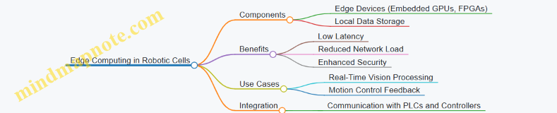
3D Vision and Depth Sensing
3D vision systems, including stereo cameras, structured light, and time-of-flight sensors, provide depth information critical for precise object localization and manipulation.
Example: A robotic cell assembling automotive components uses structured light 3D vision to detect part orientation and adjust robot trajectories accordingly, reducing mispick errors by 30%.
Mind Map: 3D Vision Technologies
Hyperspectral Imaging
Hyperspectral cameras capture image data across multiple wavelengths, enabling material identification and quality assessment beyond visible spectrum.
Example: In a food packaging robotic cell, hyperspectral imaging detects foreign contaminants and verifies product freshness in real-time, enhancing quality control.
Mind Map: Hyperspectral Imaging
AI-Powered Image Processing and Event-Based Cameras
AI algorithms enable faster and more accurate image analysis, while event-based cameras capture changes in a scene asynchronously, reducing data load and improving reaction times.
Example: A robotic cell uses AI-powered vision to identify defects on fast-moving conveyor belts, with event-based cameras triggering immediate robot intervention only when anomalies are detected.
Mind Map: AI and Event-Based Vision
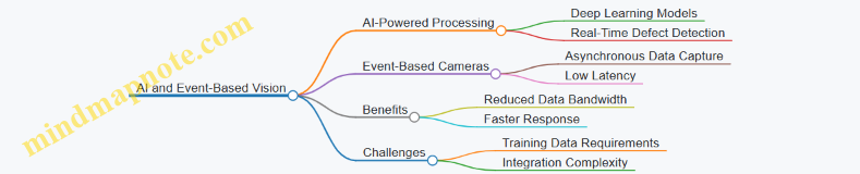
Embedded Vision Systems and IoT Connectivity
Compact embedded vision systems integrated directly into robotic end-effectors enable decentralized processing. Coupled with IoT connectivity, they facilitate Industry 4.0 data exchange and remote monitoring.
Example: A robotic cell employs embedded vision modules on each robot arm to perform localized inspection, transmitting results over an industrial IoT network for centralized analytics.
Mind Map: Embedded Vision and IoT
Digital Twins and Augmented Reality (AR)
Digital twins create virtual replicas of robotic cells for simulation and optimization, while AR tools assist operators in calibration, maintenance, and training by overlaying digital information on physical equipment.
Example: An integrator uses a digital twin to simulate motion and vision system interactions before deployment, and AR glasses to guide technicians through calibration steps on the shop floor.
Mind Map: Digital Twins and AR
Summary
Emerging technologies in motion control and machine vision are transforming high throughput robotic cells by enabling faster, more precise, and intelligent automation. By understanding and integrating these innovations, engineers can design systems that are more adaptable, efficient, and future-proof.
For further exploration, consider hands-on experimentation with AI-driven controllers, 3D vision sensors, and edge computing platforms to evaluate their impact on your specific robotic cell applications.
10.2 Collaborative Robots and Human-Robot Interaction
Collaborative robots, or cobots, are designed to work safely alongside human operators, enhancing productivity and flexibility in industrial environments. Unlike traditional industrial robots that operate in isolated cells, cobots enable direct human-robot interaction (HRI), facilitating tasks that require a combination of human dexterity and robotic precision.
Key Features of Collaborative Robots
- Safety First: Equipped with sensors and force-limiting technology to prevent injuries.
- Ease of Programming: Intuitive interfaces and teach pendants allow operators without deep programming skills to set up tasks.
- Flexibility: Easily re-deployable for different tasks and adaptable to changing production needs.
Mind Map: Core Aspects of Collaborative Robots
Human-Robot Interaction (HRI) in Industrial Settings
HRI focuses on how humans and robots communicate and collaborate effectively. In high throughput robotic cells, seamless interaction reduces cycle times and enhances quality.
Interaction Modalities
- Physical Interaction: Hand-guiding cobots to teach trajectories or assist in tasks.
- Visual Interaction: Using machine vision to interpret human gestures or presence.
- Auditory Interaction: Voice commands for robot control and status updates.
Mind Map: Human-Robot Interaction Modalities
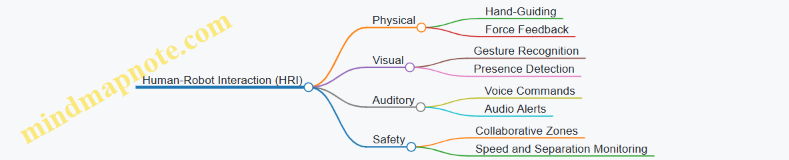
Best Practices for Implementing Cobots and HRI
- Define Clear Collaborative Tasks: Identify tasks where human intuition and robot precision complement each other.
- Ensure Safety Compliance: Implement ISO/TS 15066 standards for collaborative robot safety.
- Use Intuitive Programming Tools: Leverage hand-guiding and graphical interfaces to reduce setup time.
- Integrate Vision Systems for Awareness: Employ cameras to monitor human presence and gestures.
- Train Operators Thoroughly: Provide hands-on training to build confidence and efficiency.
Example 1: Assembly Line with Cobot-Assisted Screwdriving
In a consumer electronics assembly line, a cobot equipped with a screwdriver works alongside an operator who positions the parts. The operator places the component, and the cobot automatically screws in fasteners with precise torque control. The cobot uses force sensors to detect any obstruction and stops immediately if the operator’s hand is too close.
- Benefits: Improved ergonomics, reduced repetitive strain injuries, and increased throughput.
Example 2: Quality Inspection with Gesture-Controlled Cobot
A packaging line uses a cobot with an integrated vision system. The operator inspects products visually and uses simple hand gestures to command the cobot to pick defective items from the conveyor. The cobot recognizes gestures through a camera and responds in real-time.
- Benefits: Faster defect removal, reduced operator fatigue, and enhanced accuracy.
Mind Map: Example Use Cases of Cobots in High Throughput Cells
Challenges and Considerations
- Latency in Interaction: Ensuring real-time responsiveness to human input.
- Ergonomic Design: Designing workspaces that accommodate both human and robot movements.
- Trust and Acceptance: Building operator trust through consistent and safe robot behavior.
Summary
Collaborative robots and effective human-robot interaction are transforming high throughput robotic cells by combining the strengths of humans and machines. By following best practices and leveraging intuitive interaction modalities, systems integrators and engineers can design robotic cells that are safer, more flexible, and highly productive.
10.3 Integration of IoT and Edge Computing in Robotic Cells
The integration of Internet of Things (IoT) and edge computing technologies into high throughput robotic cells is revolutionizing industrial automation. These technologies enable real-time data processing, enhanced decision-making, and improved system responsiveness, which are critical for precision motion control and machine vision coordination.
What is IoT in Robotic Cells?
IoT refers to the network of interconnected devices and sensors that collect and exchange data. In robotic cells, IoT devices include sensors on robots, vision systems, motion controllers, and environmental monitors.
What is Edge Computing?
Edge computing involves processing data near the source (at the “edge” of the network) rather than relying solely on centralized cloud servers. This reduces latency, improves reliability, and enables faster decision-making.
Benefits of Integrating IoT and Edge Computing
- Reduced Latency: Real-time control loops for motion and vision can operate faster.
- Improved Reliability: Local processing reduces dependency on network connectivity.
- Enhanced Data Analytics: Immediate insights from sensor data enable predictive maintenance and quality control.
- Scalability: Modular addition of devices and processing units without overwhelming central systems.
Mind Map: IoT and Edge Computing in Robotic Cells
Practical Example 1: Real-Time Quality Inspection with Edge Computing
Scenario: A robotic cell assembling electronic components uses machine vision to inspect solder joints. Traditionally, images are sent to a central server for processing, causing delays.
Implementation:
- Vision cameras connected to an edge computing device process images locally.
- Defect detection algorithms run on the edge device, providing immediate feedback to the robot controller.
- If defects are detected, the robot adjusts its motion to rework or reject the part.
Outcome:
- Inspection latency reduced from seconds to milliseconds.
- Increased throughput due to faster decision-making.
- Reduced network bandwidth usage.
Mind Map: Real-Time Quality Inspection Workflow
Practical Example 2: Predictive Maintenance Using IoT Sensors and Edge Analytics
Scenario: A robotic cell experiences unexpected downtime due to motor failures.
Implementation:
- IoT sensors monitor motor temperature, vibration, and current.
- Edge computing devices analyze sensor data in real-time to detect anomalies.
- Alerts are generated locally and sent to maintenance teams before failures occur.
Outcome:
- Reduced unplanned downtime.
- Optimized maintenance schedules.
- Extended equipment lifespan.
Mind Map: Predictive Maintenance Process
Best Practices for Integrating IoT and Edge Computing
- Select Appropriate Edge Devices: Choose devices with sufficient processing power and industrial-grade reliability.
- Use Standard Communication Protocols: OPC UA and MQTT ensure interoperability.
- Implement Robust Security Measures: Secure data transmission and device authentication are critical.
- Design for Scalability: Modular architecture allows easy addition of new sensors and edge nodes.
- Optimize Data Management: Filter and preprocess data at the edge to reduce network load.
- Collaborate Across Disciplines: Integration requires coordination between robotics engineers, IT, and controls engineers.
Summary
Integrating IoT and edge computing in high throughput robotic cells enhances precision motion control and machine vision coordination by enabling faster, more reliable, and scalable data processing. Through practical implementations such as real-time quality inspection and predictive maintenance, manufacturers can achieve higher productivity and reduced downtime.
This integration represents a key step toward smarter, more autonomous industrial automation systems.
10.4 Best Practices for Preparing for Future Upgrades
In the rapidly evolving fields of precision motion control and machine vision, preparing your robotic cells for future upgrades is essential to maintain competitiveness, improve efficiency, and reduce downtime during transitions. This section outlines best practices to future-proof your systems, ensuring seamless integration of emerging technologies and scalability.
Design for Modularity and Scalability
- Modular Hardware Components: Use standardized, interchangeable modules for motion controllers, vision sensors, and actuators.
- Scalable Software Architectures: Adopt software frameworks that support plug-and-play device integration and easy updates.
Example: A robotic cell designed with modular servo drives and vision cameras allows swapping in higher resolution cameras or faster drives without redesigning the entire system.
Employ Open and Standardized Communication Protocols
- Use protocols like EtherCAT, OPC UA, or MQTT to ensure interoperability between devices from different vendors.
- Avoid proprietary systems that limit upgrade options.
Example: Integrating a new vision system from a different manufacturer is simplified when both systems communicate over OPC UA.
Implement Robust Data Management and Storage
- Design systems to handle increasing data volumes from higher resolution cameras and faster sensors.
- Use scalable storage solutions and cloud integration for data analytics and machine learning.
Example: A cell upgraded with 4K cameras requires enhanced data pipelines and storage; planning for this in advance avoids bottlenecks.
Maintain Comprehensive Documentation and Version Control
- Keep detailed records of hardware configurations, software versions, and calibration data.
- Use version control systems for software and configuration files to track changes and facilitate rollbacks.
Example: When upgrading motion control firmware, having version history helps quickly revert if issues arise.
Plan for Regular Training and Skill Development
- Invest in ongoing training for engineers and operators on new technologies and upgrade procedures.
- Encourage cross-disciplinary knowledge in motion control, vision systems, and integration.
Example: Before deploying an AI-based vision upgrade, conduct workshops to familiarize the team with new software tools.
Conduct Pilot Testing and Phased Rollouts
- Test upgrades in a controlled environment before full deployment.
- Use phased rollouts to minimize production disruption.
Example: Introducing a new motion control algorithm first on a single robot cell before scaling to the entire line.
Build Flexibility into Mechanical Design
- Design fixtures, mounts, and tooling to accommodate future sensor or end-effector changes.
- Use adjustable or universal mounts for cameras and sensors.
Example: A vision system mount designed with adjustable brackets allows easy repositioning when upgrading to a different camera model.
Summary
Preparing for future upgrades requires a holistic approach that combines modular design, open communication, data readiness, thorough documentation, continuous training, careful testing, and mechanical flexibility. By embedding these best practices into your robotic cell design and operational procedures, you ensure your system remains adaptable, efficient, and ready to leverage the latest advancements in precision motion control and machine vision.
Final Example: Preparing a Robotic Cell for AI-Enhanced Vision Upgrade
A manufacturing plant designed its robotic cell with modular cameras and EtherCAT communication. The team maintained detailed documentation and used version control for software. Prior to upgrading to an AI-based defect detection system, they conducted training sessions and pilot tests on one cell. Adjustable mounts allowed quick camera swaps. The phased rollout minimized downtime, and cloud storage handled increased data from AI processing. This preparation enabled a smooth transition, improving throughput and quality without major disruptions.
10.5 Example: Implementing Augmented Reality for Maintenance and Training
Augmented Reality (AR) is revolutionizing maintenance and training processes in high throughput robotic cells by overlaying digital information onto the physical environment. This integration enhances understanding, reduces downtime, and improves operator proficiency.
What is Augmented Reality in Industrial Robotics?
AR involves using devices such as smart glasses, tablets, or head-mounted displays to project real-time data, instructions, or 3D models directly onto the user’s field of view. In robotic cells, AR can guide technicians through complex maintenance tasks or train new operators with interactive, step-by-step visual aids.
Benefits of AR in Maintenance and Training
- Reduced Downtime: Faster diagnosis and repair through guided instructions.
- Improved Accuracy: Visual overlays reduce human error.
- Enhanced Learning: Interactive training accelerates skill acquisition.
- Remote Assistance: Experts can provide real-time support remotely.
Implementation Workflow
Example Scenario: AR-Guided Maintenance on a Robotic Arm
Context: A robotic arm in a high throughput assembly line requires periodic calibration and occasional troubleshooting.
Step-by-step AR Implementation:
- Hardware Setup: Technician wears AR smart glasses connected to the plant’s network.
- System Integration: AR software interfaces with the robot’s motion controller and vision system to retrieve real-time status.
- Interactive Overlay: When the technician looks at the robotic arm, the AR device displays:
- Component labels (motors, encoders, cables).
- Current calibration values.
- Visual indicators of parts requiring attention.
- Guided Procedure: The AR system provides step-by-step instructions for recalibration, including animations showing how to adjust joints.
- Safety Alerts: The AR device warns if the robot is powered or in motion.
- Remote Support: If the technician encounters an issue, they can stream their view to a remote expert who can annotate the AR display in real-time.
Mind Map: AR-Guided Maintenance Workflow
Example Scenario: AR-Based Training for New Operators
Context: New robotics engineers need to learn the operation and troubleshooting of a vision-guided pick-and-place robotic cell.
Training Features:
- Immersive Simulation: Trainees use AR headsets to visualize the robotic cell in their physical space.
- Interactive Tutorials: Step-by-step guidance on robot programming, vision system calibration, and safety protocols.
- Real-Time Feedback: The system monitors trainee actions and provides corrective suggestions.
- Scenario-Based Learning: Simulated faults and emergency situations to practice responses.
Mind Map: AR Training Program Components
Best Practices for AR Implementation
- User-Centered Design: Tailor AR content to the skill level and needs of users.
- Seamless Integration: Ensure AR systems communicate effectively with existing robotic controllers and vision systems.
- Content Quality: Use high-fidelity 3D models and clear, concise instructions.
- Safety First: Incorporate real-time safety alerts and fail-safes.
- Regular Updates: Keep AR content current with system changes and process improvements.
Summary
Implementing augmented reality for maintenance and training in high throughput robotic cells enhances operational efficiency, reduces errors, and accelerates workforce development. By combining AR hardware, software, and well-designed content with integration into motion control and machine vision systems, companies can achieve smarter, safer, and more agile robotic operations.
11. Conclusion and Practical Takeaways
11.1 Summary of Key Concepts and Best Practices
In this section, we consolidate the essential concepts and best practices discussed throughout the blog on precision motion control and machine vision coordination in high throughput robotic cells. This summary aims to provide a clear, actionable framework for robotics engineers, controls engineers, and systems integrators to design, implement, and optimize advanced robotic cells.
Key Concepts Mind Map
Best Practices Mind Map
Practical Examples Summary
-
Closed-Loop Control on SCARA Robot:
- Implementing encoder feedback to achieve repeatability within ±0.01 mm.
- Example: A packaging line where precise pick-and-place reduces product damage.
-
Vision-Guided Pick-and-Place:
- Synchronizing camera triggers with robot motion to correct part position in real-time.
- Example: Electronics assembly where components vary slightly in orientation.
-
Automated Calibration Procedure:
- Using a calibration grid and vision system to map robot coordinates to camera coordinates automatically.
- Example: Multi-robot cell where frequent recalibration is needed due to thermal drift.
-
Safety Zones with Machine Vision:
- Defining virtual safety zones monitored by cameras to halt robot motion if humans enter.
- Example: Collaborative robot workspace ensuring operator safety without physical barriers.
-
Real-Time Monitoring Dashboard:
- Integrating motion and vision data streams to visualize throughput, error rates, and maintenance alerts.
- Example: Automotive assembly line dashboard enabling quick response to anomalies.
Final Takeaway
The integration of precision motion control with machine vision in high throughput robotic cells requires a holistic approach—from system design to operation and continuous improvement. Leveraging best practices such as modular design, closed-loop control, real-time synchronization, and AI-driven optimization ensures robust, scalable, and efficient robotic cells capable of meeting the demanding requirements of modern industrial automation.
11.2 Checklist for Designing and Implementing High Throughput Robotic Cells
Designing and implementing high throughput robotic cells requires a systematic approach to ensure precision, efficiency, and reliability. Below is a comprehensive checklist that integrates best practices, practical considerations, and examples to guide Robotics Engineers, Controls Engineers, and Systems Integrators through the process.
Define System Requirements and Objectives
- Identify throughput targets and cycle time requirements.
- Specify precision and repeatability standards.
- Determine types of parts and processes involved.
- Assess environmental conditions (temperature, dust, vibration).
Example: For an electronics assembly line, the system must place components with ±0.05 mm accuracy at 60 units per minute.
Select Appropriate Robotic Hardware
- Choose robot type (e.g., SCARA, Cartesian, 6-axis) based on workspace and payload.
- Select motion control hardware (servo drives, controllers) with required resolution.
- Ensure compatibility with vision system mounting and integration.
Example: A 6-axis articulated robot with high-resolution encoders is selected for complex 3D part manipulation.
Design and Integrate Machine Vision System
- Select camera type (area scan, line scan, 3D) appropriate for inspection or guidance.
- Design lighting setup to minimize shadows and reflections.
- Define image processing algorithms for detection, measurement, or identification.
Example: Use a 3D stereo vision camera with structured light to detect part orientation on a conveyor.
Develop Motion and Vision Coordination Strategy
- Define communication protocols (EtherCAT, PROFINET, etc.) for real-time data exchange.
- Establish synchronization methods between robot motion and vision triggers.
- Implement feedback loops for dynamic correction based on vision data.
Example: Vision system triggers robot pick operation only after confirming part presence and orientation.
System Architecture and Control Integration
- Design modular control architecture separating PLC, motion controller, and vision processor.
- Ensure network topology supports low latency and high bandwidth.
- Plan for scalability and future expansions.
Example: Use a distributed control system with dedicated vision processing units communicating over EtherCAT.
Calibration and Alignment
- Perform camera intrinsic calibration to correct lens distortion.
- Align robot coordinate system with vision coordinate system using calibration targets.
- Schedule routine calibration checks to maintain accuracy.
Example: Use a calibration grid and robot-mounted calibration tool to align coordinate frames within 0.02 mm.
Implement Safety Measures
- Integrate vision-based safety systems for collision detection.
- Define safety zones and emergency stop protocols.
- Comply with relevant safety standards (ISO 10218, ANSI/RIA R15.06).
Example: Vision system monitors human presence and slows robot speed or stops operation if detected.
Testing and Validation
- Conduct dry runs to verify motion and vision synchronization.
- Validate precision and throughput against specifications.
- Perform robustness testing under varying environmental conditions.
Example: Run a 24-hour continuous operation test to identify potential drift or failures.
Performance Monitoring and Maintenance
- Implement real-time monitoring dashboards for key metrics.
- Set up predictive maintenance alerts based on sensor data.
- Plan for regular software updates and hardware inspections.
Example: Use vision data analytics to predict camera lens contamination and schedule cleaning.
Mind Map: High Throughput Robotic Cell Design Checklist
Mind Map: Motion and Vision Coordination Focus
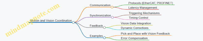
Practical Example Summary
Scenario: Implementing a high throughput robotic cell for packaging small mechanical parts.
- Requirements: 100 units/min, ±0.1 mm placement accuracy.
- Robot: SCARA with high-speed servo drives.
- Vision: Area scan camera with ring lighting for part presence and orientation.
- Coordination: EtherCAT network with synchronized triggers.
- Calibration: Weekly automated calibration routine using a precision target.
- Safety: Vision-based human detection with immediate robot stop.
- Monitoring: Dashboard showing throughput, error rates, and maintenance alerts.
This checklist ensures that all critical aspects are addressed, leading to a robust, efficient, and precise robotic cell capable of meeting demanding industrial throughput requirements.
11.3 Final Example: End-to-End Workflow of a Vision-Guided Precision Motion Cell
In this section, we will explore a comprehensive example that ties together the concepts of precision motion control and machine vision coordination within a high throughput robotic cell. This end-to-end workflow demonstrates how these technologies integrate seamlessly to achieve high accuracy, speed, and reliability in an industrial automation environment.
Workflow Overview Mind Map
Step 1: Part Presentation and Detection
The process begins with parts arriving on a conveyor belt. The machine vision system continuously monitors the conveyor to detect the presence of parts. Using simple thresholding and edge detection algorithms, the vision system identifies when a part enters the robot’s working area.
Example: A camera mounted above the conveyor captures images at 60 fps. When a part is detected, the system triggers the next step.
Step 2: Part Identification
Once detected, the vision system captures a high-resolution image to identify the part type. This is critical in mixed-model production lines.
Best Practice: Use template matching or feature-based recognition algorithms to differentiate parts.
Example: The system uses OpenCV’s feature matching to identify whether the part is a gear or a bracket.
Step 3: Position and Orientation Detection
The vision system calculates the exact X, Y, Z coordinates and the orientation angle (theta) of the part relative to the robot’s coordinate frame.
Calibration: The camera and robot coordinate systems are aligned using a calibration grid.
Example: Using a 2D vision system with a calibrated camera, the part’s centroid and orientation are computed with sub-millimeter accuracy.
Step 4: Motion Planning
The robot controller receives the position and orientation data and plans a trajectory to pick the part without collisions or delays.
Best Practice: Implement smooth trajectory planning algorithms such as cubic splines or trapezoidal velocity profiles to minimize vibration.
Example: The robot uses a trapezoidal velocity profile to approach the part, ensuring gentle acceleration and deceleration.
Step 5: Pick Operation
The robot executes the planned motion to pick the part using an appropriate end-effector.
Example: A vacuum gripper engages the part, with force sensors confirming a secure grip.
Step 6: Quality Inspection
Before placement, the vision system inspects the picked part for defects such as scratches, missing features, or incorrect orientation.
Best Practice: Use high-contrast lighting and edge detection algorithms for reliable defect detection.
Example: The system detects a missing hole on a bracket and flags the part for rejection.
Step 7: Placement Operation
The robot moves the part to the assembly or packaging station, placing it precisely according to the process requirements.
Example: The robot places the part onto a fixture with a positional tolerance of ±0.1 mm.
Step 8: Feedback Loop
After placement, the vision system verifies the part’s position and orientation. If deviations are detected, the robot can make micro-adjustments.
Example: Vision detects a slight misalignment and commands the robot to nudge the part into the correct position.
Step 9: Cycle Repeat
The system resets sensors and prepares for the next part, maintaining high throughput.
Integrated Mind Map: Vision and Motion Coordination
Summary
This example illustrates how precision motion control and machine vision are tightly integrated to enable a high throughput robotic cell capable of accurate, reliable, and flexible operation. By following best practices such as robust calibration, real-time synchronization, and continuous feedback, engineers can design systems that maximize productivity and quality.
Additional Example: Simple Code Snippet for Vision-to-Robot Communication
# Pseudocode for sending vision coordinates to robot controller

import socket

# Vision system calculates coordinates
part_position = {'x': 150.25, 'y': 75.80, 'theta': 5.2}  # in mm and degrees

# Connect to robot controller
robot_ip = '192.168.1.10'
robot_port = 30002
sock = socket.socket(socket.AF_INET, socket.SOCK_STREAM)
sock.connect((robot_ip, robot_port))

# Format message
message = f"MOVE_TO {part_position['x']} {part_position['y']} {part_position['theta']}\n"

# Send coordinates
sock.sendall(message.encode())

# Close connection
sock.close()
This snippet demonstrates a simple TCP/IP communication where the vision system sends calculated coordinates to the robot controller for motion execution.
By understanding and implementing this end-to-end workflow, robotics engineers, controls engineers, and systems integrators can develop advanced robotic cells that meet the demanding requirements of modern industrial automation.
11.4 Resources for Further Learning and Development
To deepen your understanding and enhance your skills in precision motion control and machine vision coordination within high throughput robotic cells, the following resources are invaluable. They include books, online courses, software tools, communities, and mind maps to organize your learning journey.
Recommended Books
-
“Robotics: Control, Sensing, Vision, and Intelligence” by K.S. Fu, R.C. Gonzalez, and C.S.G. Lee
- Comprehensive coverage of robotics fundamentals including motion control and vision.
-
“Machine Vision” by Ramesh Jain, Rangachar Kasturi, and Brian G. Schunck
- A classic text focusing on image processing and vision system design.
-
“Mechatronics: Principles and Applications” by Godfrey C. Onwubolu
- Covers integration of mechanical, electronic, and control systems.
-
“Modern Robotics: Mechanics, Planning, and Control” by Kevin M. Lynch and Frank C. Park
- Advanced concepts in robot kinematics and control.
Online Courses and Tutorials
-
Coursera: “Robotics Specialization” by University of Pennsylvania
- Modules on perception, motion planning, and control.
-
edX: “Control of Mobile Robots” by Georgia Tech
- Focus on motion control algorithms.
-
Udemy: “Machine Vision and Image Processing with OpenCV”
- Hands-on tutorials on vision system implementation.
-
MIT OpenCourseWare: “Introduction to Robotics”
- Free lectures covering robotics fundamentals.
Software Tools and Libraries
-
ROS (Robot Operating System)
- Open-source framework for robot software development, including motion control and vision integration.
-
OpenCV
- Widely used open-source computer vision library.
-
MATLAB Robotics System Toolbox
- Provides algorithms and tools for designing and testing robotics applications.
-
LabVIEW
- Graphical programming environment often used for machine vision and motion control integration.
Professional Communities and Forums
-
IEEE Robotics and Automation Society
- Access to journals, conferences, and networking.
-
Robotics Stack Exchange
- Q&A site for robotics engineers.
-
GitHub
- Explore open-source projects related to motion control and vision.
-
LinkedIn Groups
- Groups like “Industrial Robotics” and “Machine Vision Professionals” for discussions and job opportunities.
Mind Maps for Structured Learning
Mind Map 1: Core Concepts in Precision Motion Control
Mind Map 2: Machine Vision System Components
Mind Map 3: Integration and Coordination
Practical Examples and Tutorials
-
Example 1: Vision-Guided Pick-and-Place Robot Tutorial
- Step-by-step guide on integrating OpenCV with a robotic arm for part localization and handling.
- GitHub Repository
-
Example 2: Calibration of Robot and Camera Systems
- Detailed procedure using MATLAB and ROS for coordinate system alignment.
- MATLAB Tutorial
-
Example 3: Implementing Real-Time Motion Control with Feedback
- Using LabVIEW and NI hardware to achieve closed-loop control.
- NI Example Projects
Summary
These resources provide a comprehensive foundation and advanced insights into precision motion control and machine vision coordination. By leveraging books, courses, software, communities, and structured mind maps, engineers and integrators can continuously improve their systems, stay updated with industry trends, and solve complex challenges effectively.