FAA Airframe and Powerplant Mechanic Exam Prep
1. Exam Foundations and Maintenance Documentation
1.1 Understanding FAA Exam Structure and Task Based Questions
FAA Airframe and Powerplant (A&P) exams are built around tasks you can actually perform, not around trivia you can only memorize. The key idea is simple: each question is tied to a job step, and the best answer is the one that matches the correct procedure, inspection logic, or safety requirement.
What Task Based Questions Really Test
Task based questions usually test one of four things: (1) identifying what to inspect, (2) recognizing acceptable condition versus reject condition, (3) choosing the correct procedure or tool, or (4) applying the right safety and documentation step. For example, if a question mentions a specific inspection interval and a defect type, it’s usually asking what you must do next—measure, verify, remove, or document.
A common trap is treating the question like a general knowledge prompt. Instead, treat it like a work order. Ask: What is the aircraft system or component? What is the symptom or condition described? What action is required by the task?
How the Exam Is Organized
The A&P exam is divided into sections that map to major maintenance areas. Within each section, questions are grouped by subject matter and task type. You’ll see a mix of airframe and powerplant topics, but the exam style stays consistent: short scenarios, then a single best answer.
A helpful mental model is a three-layer stack:
- Subject area (for example, electrical, sheet metal, fuel, ignition)
- Task (inspect, test, measure, repair, verify)
- Decision rule (pass/fail criteria, correct sequence, correct safety step)
When you read a question, identify the subject area first, then locate the task verb. “Inspect,” “check,” “determine,” “verify,” and “select” are not decorative; they tell you what the question is really asking.
Reading Questions Like a Mechanic
Start by underlining the condition described. If the question says “evidence of chafing,” your next step is to look for the correct inspection or corrective action. If it says “incorrect torque,” your next step is to look for the correct torque procedure or rework requirement.
Next, scan for constraints. Constraints include: required tools, acceptable limits, safety steps, and whether the task is preflight, post-maintenance, or troubleshooting. If the question mentions “after installation” or “after repair,” it’s often testing verification steps rather than initial inspection.
Finally, eliminate answers that violate the decision rule. If the question is about inspection acceptability, an answer that describes a repair method without addressing the accept/reject logic is usually wrong.
Example: Turning a Scenario into a Task
Scenario: A mechanic finds corrosion around a fastener hole and is preparing to decide what to do next.
Task based interpretation: The question is likely testing inspection classification and the correct next action, not just naming corrosion types.
Best answer logic: Choose the option that matches the required inspection step and the correct corrective action sequence, such as cleaning and assessing severity, then following the applicable repair or replacement criteria.
Notice what’s missing: you don’t need to guess the aircraft model. You need to apply the task logic: inspect condition → classify → decide acceptable versus reject → follow the required procedure.
Example: Electrical Question with a Hidden Task
Scenario: A question describes a wiring issue and asks what to do to restore correct operation.
Task based interpretation: The task is often “verify” or “test,” not “guess.”
Best answer logic: Select the option that uses the correct diagnostic approach and verification method, such as checking continuity or insulation resistance as appropriate, then confirming the circuit returns to normal operation.
If an answer skips the verification step and jumps straight to replacement, it may be tempting—but task based questions usually reward the procedure that proves the fix.
Mind Map: Exam Structure to Answer Selection
A Simple Workflow for Every Question
- Identify the component or system.
- Locate the task verb.
- Extract the condition and any limits or constraints.
- Choose the answer that performs the required task in the correct order.
- Confirm the answer matches the decision rule implied by the scenario.
If you follow that workflow consistently, the exam stops feeling like a puzzle box and starts behaving like a set of job steps—because that’s exactly what it is.
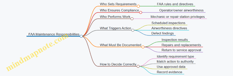
1.2 Interpreting Regulations for Maintenance Responsibilities
Maintenance responsibility in the FAA system is less about memorizing rules and more about matching the right action to the right authority, record, and limitation. On the exam, the trick is usually the same: identify what you are allowed to do, what you must document, and what you must not do outside the approved scope.
Core Regulatory Roles and How They Show Up
Start with three roles that repeatedly appear in questions: the FAA, the operator/owner, and the certificate holder performing maintenance. The FAA establishes requirements; the operator ensures the aircraft is maintained in an airworthy condition; the maintenance organization or mechanic performs work within their certificate privileges.
A practical way to reason through a scenario is to ask three questions in order:
- What requirement is being referenced? (airworthiness, inspection, maintenance, or approval)
- Who is responsible for compliance? (operator vs. maintenance provider)
- What evidence must exist afterward? (maintenance records, inspection findings, or approval for return to service)
What “Airworthy” Means in Maintenance Terms
“Airworthy” is not a vibe; it is a condition where the aircraft conforms to its type design and is in a safe state for operation. Regulations tie airworthiness to maintenance actions and inspections. If a defect is found, the responsibility shifts from “inspect” to “evaluate and correct” based on the applicable inspection program and approved data.
Example: During a landing gear inspection, you find a cracked fairing bracket. The regulation logic is: the inspection requirement is satisfied by finding the condition, but airworthiness requires the condition be evaluated and corrected using approved data, then properly documented.
Inspection Requirements and the Maintenance Program
Many exam items hinge on whether an inspection is required by the maintenance program or by an airworthiness directive. If an inspection is required, you must follow the scope and intervals in the applicable program, and you must record results as required. If you find discrepancies, you must follow the disposition process in the approved data.
Example: A scheduled inspection calls for checking a specific wiring bundle for chafing. You inspect the bundle, find no damage, and record the result. If you find chafing, you do not “close it out” with a casual note; you repair or replace using approved methods and then record what was done and why it is acceptable.
Maintenance Records and Return to Service Logic
Regulations require that maintenance performed be documented in a way that supports traceability. Records typically include what was done, when it was done, who did it, and what data or references were used. Return to service is a separate step: the aircraft is not simply “fixed,” it is approved for service based on the required sign-off process.
Example: You replace a component using approved data. The work is complete, but the aircraft still needs the correct return-to-service documentation before it can be released for operation.
Limits of Authority and Scope of Work
Certificate privileges matter. A mechanic or repair station can only perform tasks within the scope allowed by their certification and the aircraft’s maintenance program. If a task requires a different approval path, the correct action is to route it to the appropriate authority rather than improvise.
Example: If a question describes a repair that requires specific approval beyond what the mechanic’s privileges cover, the correct response is to ensure the repair is performed under the proper approval process and documented accordingly.
Mind Map: Regulations to Responsibilities
Case Study: Interpreting a Mixed-Requirement Scenario
A question describes a routine inspection plus a separate directive requirement. The correct approach is to treat them as distinct obligations: the routine inspection follows the maintenance program, while the directive has its own compliance requirements. If both apply, you complete both sets of actions, then document results in a way that shows each obligation was addressed.
Example: A scheduled inspection finds a minor discrepancy that is not addressed by the directive. You still must correct the discrepancy to maintain airworthiness, but you must also complete the directive actions on schedule. Your records should reflect both outcomes without blending them into one vague statement.
Quick Exam Checklist for Responsibility Questions
When you see a maintenance responsibility question, scan for these cues: inspection type, who is authorized to perform the task, what happens after a defect is found, and what documentation is required for return to service. If any of those elements are missing, the best answer usually points to the missing responsibility step rather than the technical fix.
1.3 Using Maintenance Manuals and Illustrated Parts Catalogs
Maintenance manuals and illustrated parts catalogs (IPCs) are the “how” and the “what.” The manual tells you what to inspect, how to do it, and what limits matter. The IPC tells you what parts exist, how they fit together, and how they’re identified for ordering and replacement. Using them together prevents the classic mistake of performing the right procedure on the wrong component.
Core Roles of Each Document
A maintenance manual section is usually organized by system or task, then by aircraft model or configuration. It often includes prerequisites such as aircraft condition, access requirements, and safety steps. When a task says “inspect,” it typically specifies inspection method, reference points, and acceptance criteria.
An IPC is organized by assemblies and subassemblies. It provides part numbers, nomenclature, and sometimes alternate part numbers or kits. The IPC also helps you confirm whether a fastener, seal, or fitting is a one-off item or part of a larger kit. If the manual references a part by name but not by part number, the IPC bridges that gap.
How to Read a Task in the Maintenance Manual
Start by locating the task title and task number, then confirm the applicability. Many tasks include model, serial number, or configuration notes. Next, read the objective line that describes what the task accomplishes, such as verifying security, measuring clearances, or checking for leakage.
Then follow the procedure steps in order. If the procedure includes “remove and reinstall,” note torque values, safetying methods, and any required sealant or lubricant callouts. If the procedure includes measurements, identify the tool and the measurement location. A good habit is to underline acceptance criteria and circle the measurement points before you begin.
Finally, check the “results” or “task completion” section. It may specify what to record in the logbook, what to attach, or what to report if limits are exceeded.
How to Use the IPC Without Guessing
Begin with the assembly diagram that matches the manual’s system. Use the diagram to identify the exact subassembly and then locate the part number list. Confirm the part’s nomenclature matches the manual’s description.
When you see multiple similar items, pay attention to index numbers and location codes. For example, two identical-looking clamps may differ by part number because one includes a different coating or length. If the manual says “replace the clamp,” the IPC helps you replace the correct clamp, not the closest-looking one.
Also watch for kits and service bulletins. An IPC may show a “replacement” part number or a kit that includes multiple components. If the manual procedure calls for replacing a seal and a gasket, the IPC can reveal whether they are sold separately or as a kit.
Integrated Workflow for a Real Task
Example: A manual task requires inspecting a fuel line fitting for security and signs of leakage.
- Use the maintenance manual to identify the exact inspection location and the acceptance criteria for leakage.
- Note any required access steps, such as removing a fairing or opening an access panel.
- Use the IPC to identify the fitting and adjacent components, including any clamps, seals, or adapters.
- If the inspection finds a problem, use the IPC to confirm the correct replacement part number(s) before ordering.
- Return to the maintenance manual for the replacement procedure, including torque and any sealant or safetying requirements.
This workflow keeps you from doing “inspection-only” thinking when the task might turn into “repair-and-record” thinking.
Mind Map: Maintenance Manuals and Illustrated Parts Catalogs
Common Pitfalls and How to Avoid Them
A frequent pitfall is treating the IPC as a procedure source. It isn’t. It tells you what exists and how it’s identified, not how to perform the inspection or replacement. Another pitfall is treating the maintenance manual as a parts source. If the manual names a component but doesn’t provide a part number, you still need the IPC to order the correct item.
A practical check is to cross-reference the manual’s component name with the IPC’s nomenclature. If they don’t match cleanly, stop and resolve the mismatch before you proceed. That one pause prevents rework, delays, and the awkward moment of realizing you replaced the wrong “almost the same” part.
Example: Matching a Manual Callout to an IPC Item
Suppose the manual says “inspect the bonding jumper at the battery tray.” The IPC diagram for the battery tray assembly can show a bonding jumper with a specific index number. Once you identify that index number, you can confirm the exact part number and any alternate options. If replacement is required, you then return to the manual to follow the correct installation steps, including any required torque and safetying method.
Using both documents this way keeps your work consistent: the manual governs the method, and the IPC governs the identity.
1.4 Applying Inspection Records and Maintenance Log Requirements
Inspection records are the aircraft’s memory. They show what was checked, what was found, what was done, and why the aircraft is still considered airworthy. On the exam, questions often test whether you can connect an inspection action to the correct documentation outcome.
Core Purpose of Maintenance Logs
Start with the goal: maintenance log entries provide traceability. If an inspector later asks, “When was this inspected, and what did the inspection lead to?”, the record should answer without guessing. A good entry also supports continuity between mechanics, because the next person inherits the same facts you had.
A practical way to remember this is to treat every inspection as having four outputs:
- Identity: which aircraft and component.
- Evidence: what was inspected and how.
- Result: pass, discrepancy, or limitation.
- Disposition: repair, adjustment, replacement, or deferral with the correct basis.
What Must Be Recorded
The exam typically expects you to record discrepancies and the actions taken to correct them. If an inspection finds no discrepancies, you still document that the inspection occurred, especially when the task is required by an inspection program or maintenance schedule.
When a discrepancy is found, the log entry should include:
- Description of the discrepancy in plain terms (for example, “corrosion pitting on lower wing skin, left side”).
- Location and extent (for example, “between ribs 3 and 4, 2-inch diameter area”).
- Reference to inspection criteria when applicable (for example, the inspection task or manual section used).
- Corrective action performed, including part numbers or work scope when required.
- Return to service basis such as completed repairs and any required inspections.
Example: Simple Inspection with No Findings
A mechanic performs a required inspection of a landing gear strut for leaks and finds none. The log entry should state that the inspection was performed, identify the component, and note “no discrepancies found.” You do not need a novel description of the strut’s entire life story, but you do need enough detail to prove the correct item was checked.
Example: Discrepancy Found and Corrected
During a preflight inspection, a mechanic notices a cracked fairing fastener. The log entry should record the discrepancy, where it was located, the fastener identification, and that the fastener was replaced with the correct part. If the repair required additional steps like torque verification or safetying, those actions should be included.
How to Apply Timing and Aircraft Usage Data
Many log requirements depend on time or cycles. Use the aircraft’s current usage data correctly, because it anchors the record to the maintenance schedule.
A common exam trap is mixing up units or writing “completed at 1,200 hours” when the aircraft was actually at 1,200 cycles. If the task is hour-based, the entry must reflect hours.
If a date is required in an entry, use the actual completion date. For example, an entry might read “Completed 2026-02-15” if that is the day the work was finished.
Mind Map: Inspection Records and Log Entries
Advanced Details That Show Up on the Exam
Discrepancy Clarity
Vague entries are a documentation failure. “Checked and repaired” is not enough because it does not tell what was wrong or what changed. A stronger entry ties the discrepancy to the corrective action.
Verification and Follow-Up
Some repairs require a subsequent inspection to confirm the fix. If the task includes a verification step, the log should reflect that verification occurred, not just that the repair was attempted.
Consistency with Approved Data
When the work uses approved data, the log entry should reflect that the work was performed in accordance with the applicable instructions. You do not need to copy entire procedures, but you should avoid implying a generic fix when the task required a specific method.
Case Example: Turning Notes into a Compliant Entry
A mechanic writes in a notebook: “Noticed oil seep at accessory case seam during inspection. Cleaned area. Rechecked after run; seep continued.” The compliant log entry should convert that into:
- what was inspected (accessory case seam area),
- what was found (oil seep/discrepancy),
- what was done (cleaned, rechecked, then corrective action performed), and
- the outcome (seep corrected and verified).
The exam rewards this conversion mindset: raw observations become structured record content.
Quick Checklist for Exam Answers
- Did you identify the aircraft/component?
- Did you state the inspection result?
- If there was a discrepancy, did you document location, extent, and disposition?
- Did you include correct date and the right usage basis?
- Did you show verification when the task required it?
When you answer exam questions, treat the log entry as a short, factual report that another mechanic could use to continue the work without asking you questions.
1.5 Using Tooling Manuals and Calibration Records for Compliance
Tooling manuals and calibration records are how you prove that the tools used for inspection and maintenance are fit for purpose. The key idea is simple: the aircraft doesn’t care that you “meant well,” but the documentation can show that you followed the approved process.
Foundational Concepts You Must Get Right
Start with the tooling manual. It tells you which tools are approved for a task, how they should be set up, and what acceptance criteria apply. If a task requires a specific torque wrench type, adapter, or alignment fixture, the tooling manual is where that requirement lives.
Next is calibration. Calibration records show that a measuring or test tool was checked against a known standard, within a defined interval, and that it met tolerance. If the tool is out of calibration, you may still be able to use it for non-critical tasks, but for compliance-related measurements you must follow the maintenance organization’s policy and the tool’s status.
A practical way to remember the relationship: tooling manuals define the “how,” calibration records confirm the “how well.”
Reading Tooling Manuals Like a Checklist
Use a consistent reading path:
- Task linkage: Identify the exact maintenance task or inspection step the tooling manual supports. Don’t rely on tool names alone; tasks can specify different setups.
- Tool identification: Confirm part numbers, model numbers, and any required accessories. Example: a borescope might require a specific probe length or image orientation adapter.
- Setup requirements: Note pre-use steps such as zeroing, warm-up, or selecting the correct scale range.
- Procedure steps: Follow the sequence. Many inspection errors come from skipping intermediate checks.
- Acceptance criteria: Record the exact pass/fail limits. If the manual says “within ±0.5 mm,” that’s not a suggestion.
Example: A tooling manual for a gap measurement may require a specific feeler gauge set and a defined measurement technique. If you use a different gauge set, your measurement might still be numerically close, but it is not the approved method.
Calibration Records That Actually Help You
A calibration record typically includes:
- Tool identification: Asset tag, serial number, and sometimes the manufacturer model.
- Calibration standard: What reference was used.
- Date performed: Use the record’s actual calibration date, not the date you found it.
- Due date or interval: When the next calibration is required.
- Results: Pass/fail, measured deviations, and any adjustments performed.
- Traceability statement: Often included to show the chain of standards.
If a record shows the tool was calibrated on 2026-02-15 with a 12-month interval, the due date is 2027-02-15. If you’re working after that due date, the tool is not compliant for measurement tasks unless your organization has an approved exception process.
Mind Map: Compliance Workflow
Integrated Example: Measuring a Control Surface Gap
Assume a task requires measuring a control surface gap using a specific fixture and a calibrated dial indicator.
- Manual step: The tooling manual specifies the fixture part number and instructs you to set the indicator to zero at a reference surface.
- Tooling match: You verify the fixture and indicator serial numbers match what your work order and manual require.
- Calibration check: You review the indicator’s calibration record and confirm it is within the due date.
- Setup: You perform the manual’s zeroing step before taking readings.
- Measurement: You take the required number of points and record each value.
- Acceptance: You compare each value to the manual’s limits. If the manual allows 1.0–1.5 mm and one point is 1.7 mm, you don’t “round” it into compliance; you follow the corrective action path.
The compliance win here is traceability: the manual defines the method, calibration confirms the tool’s measurement integrity, and the recorded results show the outcome.
Advanced Detail: When Tools Are Not Identical
Sometimes a tool looks the same but isn’t. Differences can include scale range, probe type, or adapter geometry. If the tooling manual specifies a particular adapter, using a similar one can change the measurement relationship.
When you encounter a mismatch, treat it as a documentation problem, not a “close enough” problem. Verify whether the maintenance organization has an approved substitution or whether the task must be repeated with the correct tooling.
Quick Compliance Checklist for the Exam
- Tooling manual section matches the exact task step.
- Tool and accessories match the manual’s identification requirements.
- Calibration record matches the tool’s serial number and is within due date.
- Setup steps like zeroing and range selection are completed per manual.
- Measurements are recorded and compared to the manual’s acceptance criteria.
That’s the whole system: approved method, verified tool condition, and documented results.
2. Airframe Materials Fasteners and Corrosion Control
2.1 Identifying Common Airframe Materials and Their Properties
Airframe materials are chosen for a reason: they must handle loads, resist corrosion, survive temperature swings, and still be repairable. In an exam setting, you’re often asked to connect a material to its typical inspection behavior—what you look for, how you recognize it, and what properties explain the failure mode.
Foundational Material Categories
Most airframe structures fall into four practical buckets: aluminum alloys, steels, titanium, and composites. Each bucket has a “personality” in inspection terms.
- Aluminum alloys are common in skins, spars, and ribs because they’re relatively light and easy to form. Their inspection often focuses on corrosion and fatigue cracking, especially around fasteners and joints.
- Steels show up in landing gear components and other high-load areas where strength and toughness matter. Inspection commonly targets corrosion, cracking, and wear at contact points.
- Titanium is used where corrosion resistance and strength-to-weight are valuable, often in areas exposed to harsh environments. Inspection emphasizes cracks and surface condition changes.
- Composites (fiberglass, carbon fiber, aramid fiber systems) are used for fairings, control surfaces, and other weight-sensitive parts. Inspection focuses on delamination, impact damage, and moisture-related effects.
A useful way to reason through questions is to ask: “What property would the designer prioritize here?” Then match that property to the material category.
Aluminum Alloys and Their Properties
Aluminum alloys typically balance strength, ductility, and manufacturability. A key property is that aluminum forms an oxide layer that helps corrosion resistance, but it’s not magic—corrosion can still occur, especially with trapped moisture or dissimilar-metal contact.
Common inspection cues
- Corrosion around fasteners: if you see pitting or staining near rivets or bolts, it’s often a corrosion pathway rather than random damage.
- Fatigue cracking: cracks tend to initiate where stress concentrates, such as at holes, bends, and lap joints.
- Surface oxidation and coating condition: paint and primers protect aluminum; damaged coatings can expose fresh metal.
Easy example: If a wing skin shows fretting and dark residue around a row of rivets, you’re likely dealing with corrosion and wear at the interface, not a structural “mystery crack” that started in mid-panel.
Steels and Their Properties
Steel’s standout properties are strength and toughness. It can handle high loads and impacts, which is why it’s common in landing gear hardware. The downside is corrosion susceptibility if protective coatings or plating are compromised.
Common inspection cues
- Surface rust or coating breakdown: corrosion can spread under coatings.
- Cracks at stress risers: sharp transitions, holes, and welded or heat-affected zones are common initiation points.
- Wear and deformation: contact surfaces may show measurable wear patterns.
Easy example: A brake assembly with uneven wear and corrosion on adjacent hardware suggests both mechanical wear and loss of protective integrity.
Titanium and Its Properties
Titanium offers excellent corrosion resistance and good strength, with lower density than steel. It’s often selected when the environment is tough and the structure must remain reliable.
Common inspection cues
- Crack-like indications: titanium can develop cracks that require careful interpretation.
- Surface condition changes: discoloration or unusual surface texture can indicate prior thermal or mechanical events.
Easy example: If a component shows a localized linear indication near a joint where stress concentrates, treat it as a potential crack rather than “just discoloration,” because titanium’s corrosion behavior doesn’t eliminate fatigue concerns.
Composites and Their Properties
Composites are engineered systems: fibers provide strength, and the matrix binds and transfers loads. Their behavior differs from metals because damage can be internal even when the surface looks acceptable.
Common inspection cues
- Delamination: layers separate, reducing stiffness and load transfer.
- Impact damage: dents or surface cracks may be small, but internal damage can be larger.
- Moisture effects: water can affect matrix condition and long-term performance.
Easy example: A fairing with a small scrape but a soft spot when pressed may indicate internal separation rather than superficial scuffing.
Mind Map: Airframe Materials and Properties
Property-to-Inspection Reasoning
When you see an inspection question, translate it into properties:
- If the scenario mentions fasteners, lap joints, or trapped moisture, think aluminum corrosion pathways.
- If it mentions landing gear hardware, wear, or impact, think steel toughness and coating integrity.
- If it mentions harsh environments with corrosion resistance, think titanium selection logic.
- If it mentions impact, dents, or “looks fine but feels wrong,” think composite internal damage.
That reasoning approach keeps you from guessing based on appearance alone, which is exactly what the exam tries to prevent.
2.2 Selecting and Inspecting Fasteners for Correct Installation
Fasteners are small, but they control big outcomes: structural integrity, system reliability, and corrosion resistance. Correct installation starts with choosing the right hardware for the job, then confirming the installation matches the approved data. Think of it as two checks: “Is this the correct fastener?” and “Is it installed correctly?”
Foundational Concepts for Correct Fastener Selection
Begin with the approved data for the specific aircraft and task. The maintenance manual or structural repair data will specify fastener part numbers, material, size, grip range, and any special installation requirements. If the task calls for a specific torque or tension method, that requirement is not optional.
Next, match the fastener to the environment. A fastener that works fine in a dry cabin may fail early in a wet bilge or near exhaust heat. Corrosion control is not just about coatings; it includes material pairing and whether the fastener is isolated from dissimilar metals.
Finally, confirm the fastener’s mechanical fit. Grip length must match the stack-up so the joint clamps properly. Too short means the joint may not clamp; too long can bottom out, distort parts, or interfere with adjacent components.
Fastener Identification and Verification Steps
Start with physical identification: head markings, part number on the bag or tag, and dimensions. If markings are missing or inconsistent, stop and verify through the approved parts catalog or hardware traceability process.
Then verify condition. Hardware should be clean, free of burrs, and not stretched, nicked, or corroded. For reusable fasteners, inspect threads and bearing surfaces for damage that would change friction or clamp load.
A practical example: you’re replacing a wing skin fastener. The bag label says the correct part number, but the old fastener shows thread galling. Even if the new fastener is correct, the underlying issue—such as improper lubrication type, contamination, or incorrect material pairing—must be addressed before installation.
Selecting the Correct Fastener Type
Common categories include bolts, screws, studs, nuts, rivets, and special hardware such as shear pins or cotter pins. Each category has a different failure mode and installation method.
- Bolts and nuts rely on clamp load and proper torque or tension.
- Screws often rely on thread engagement and correct driver fit.
- Rivets rely on proper forming and correct shop head dimensions.
- Safety hardware (cotter pins, lockwire, locknuts) prevents loosening and must be installed to the required pattern.
When selecting, ensure the fastener style matches the joint design. For example, replacing a structural bolt with a “similar” grade fastener is not a like-for-like swap because strength, heat treatment, and surface finish can differ.
Inspection Criteria During Installation
Inspection is not only after the fact; it’s built into the process.
- Thread engagement check: confirm the fastener length provides the required thread engagement without bottoming.
- Surface cleanliness: remove paint, corrosion, and debris where the joint requires metal-to-metal contact or where isolation materials are specified.
- Lubrication and coatings: use only the approved lubricant or anti-seize method if specified. Over-lubrication can change torque-to-tension behavior.
- Torque or tension compliance: use calibrated tools and follow the specified method. If a torque wrench is used, ensure the correct range and technique.
- Safetying verification: confirm lockwire direction, cotter pin seating, or locknut engagement as required.
A concrete example: during reassembly, a mechanic uses a power tool to “speed up” tightening. Even if the final torque number is reached, the tool may overshoot or damage the fastener head. The inspection should catch head deformation, thread damage, and incorrect safetying.
Advanced Details That Prevent Common Failures
Material pairing and isolation: If the approved data calls for washers, sleeves, or insulating coatings, install them exactly. Missing isolation can create galvanic corrosion at the joint.
Grip range and stack-up changes: If a repair changes thickness—such as adding a doubler—fastener length may need recalculation. Don’t assume the original hardware still fits the new stack-up.
Head and bearing surface integrity: Under-torque can leave gaps; over-torque can crush bearing surfaces or distort parts. Either condition can reduce clamp load stability.
Mind Map: Fastener Selection and Inspection
Quick Scenario Walkthrough
On a structural inspection task dated 2026-02-15, you’re tasked with replacing a fastener in a lap joint. The manual specifies a specific bolt length and a washer type for corrosion isolation. You verify the part number from traceability, confirm the bolt length matches the current stack-up, clean the joint surfaces where metal contact is required, and apply only the approved coating method. After tightening to the specified torque, you inspect the head for deformation and confirm the safetying method is correctly installed. If any step doesn’t match the approved data, the installation is corrected before the aircraft is returned to service.
2.3 Torque Procedures and Safetying Methods for Hardware
Torque is the bridge between “tight” and “correct.” The goal is to apply a specific clamping force so the joint stays secure without overstressing threads, fastener heads, or mating parts. Safetying methods then prevent loosening from vibration, thermal cycling, or repeated load changes.
Foundational Torque Concepts
Start with what torque actually does. Tightening a bolt mainly stretches it slightly; that stretch creates clamping force. If you under-torque, the joint may separate under load. If you over-torque, you can strip threads, yield the bolt, or distort the joint surface.
Torque values come from the aircraft maintenance manual or approved data. If a task calls for a torque range, use the specified method to land within that range. If the task specifies “torque and safety,” treat safetying as a required step, not an optional extra.
Tools and Setup That Prevent Mistakes
Use a calibrated torque wrench appropriate for the fastener size and access. A common error is using the wrong wrench type or extension that changes the effective torque. If an extension or adapter is required, follow the tool instructions or the maintenance data for compensation.
Before tightening, ensure the fastener and mating surfaces are clean and correctly installed. Dirt under a bolt head or corrosion on a mating face can reduce clamping force even when torque is correct. For hardware with specified lubrication, use only the approved lubricant and apply it exactly as directed; lubrication can significantly change the torque-to-clamp relationship.
Step-by-Step Torque Procedure
- Verify the fastener and joint condition. Confirm the correct part number, length, and washer or spacer arrangement. For example, a missing washer can change stack height and lead to incorrect clamping.
- Position the joint and align parts. Misalignment can cause uneven contact and local stress. If the joint is a control surface hinge, ensure the parts sit flush before tightening.
- Hand-start fasteners. Thread by hand to avoid cross-threading. A quick example: if a bolt stops abruptly after a few turns, stop and re-thread rather than forcing it.
- Torque in the correct sequence. For multi-fastener joints, tighten in a pattern that draws the parts together evenly. A typical example is a star pattern on a flange so the gasket or mating surfaces compress uniformly.
- Use the specified torque method. Apply torque smoothly without jerking. If the procedure calls for “torque in stages,” do it. Staged torque helps the joint settle and reduces the chance of overshooting.
- Re-check if required by the task. Some joints require a second torque check after initial seating. If the manual does not call for it, don’t invent it.
- Record and verify. Ensure the inspection or maintenance record reflects completion, and that any required witness marks are present.
Safetying Methods for Hardware
Safetying prevents loosening when vibration or load cycles reduce friction in the joint. Choose the method specified for the hardware and location.
1. Lockwire (safety wire). Used where access allows wire routing through holes in the bolt head or nut. The wire should be tensioned so it resists rotation in the loosening direction. Example: if a nut tends to loosen counterclockwise, route the wire so it pulls against that direction.
2. Cotter pins and safety clips. Common on castellated nuts. Insert the pin through the hole and bend the ends to secure it. Example: if the pin won’t align with the hole, do not “make it fit” by backing off unless the procedure allows it.
3. Locknuts and prevailing torque nuts. These rely on a built-in feature that increases resistance to rotation. Example: do not reuse a locknut if the task specifies replacement after removal.
4. Thread-locking compounds. Used when specified, typically on threaded fasteners where vibration is expected. Apply only the specified type and surface prep. Example: if the procedure calls for degreasing, wiping with a random solvent is not the same as the required prep.
5. Washers and tabbed devices. Split washers, tab washers, or bent tabs can prevent rotation. Example: ensure the tab is bent into the correct position so it actually blocks movement.
Mind Map: Torque and Safetying Workflow
Practical Example: Flange Joint with Multiple Fasteners
Imagine a flange with eight bolts. You hand-start all bolts to ensure correct thread engagement, then tighten in a star pattern. If the manual specifies staged torque, you apply the first stage to all bolts in sequence, then the final torque in the same pattern. After torque, you safety the hardware exactly as specified—if lockwire is required, wire each fastener so the wire resists rotation in the loosening direction. Finally, you verify that the wire is not contacting moving parts and that the safetying is fully seated.
Common Failure Points to Avoid
Overlooking tool calibration is a quiet way to get wrong torque. Skipping the correct sequence can warp the joint and create uneven clamping. Using the wrong safetying method can leave the joint vulnerable even when torque is correct. The best habit is simple: follow the maintenance data for torque value, sequence, method, and safetying, then verify the installed hardware matches the intent of the procedure.
2.4 Detecting Corrosion Types and Selecting Appropriate Treatments
Corrosion is metal’s way of returning to a more stable chemical state. Your job as a mechanic is to identify what kind of corrosion you’re seeing, confirm the likely cause, and then choose a treatment that matches both the damage and the environment. The exam usually tests whether you can connect the visual clues to the correct inspection and corrective actions.
Foundational Clues Before You Classify
Start with a disciplined look: location, appearance, and surrounding conditions. Corrosion that forms near drains, seams, fasteners, or areas with trapped moisture often points to a specific mechanism. For example, streaks that follow lap joints suggest water migration and capillary action, while pitting concentrated around a fastener can indicate localized attack.
Next, check for the “supporting evidence” that corrosion is active or recurring: fresh-looking surface roughness, flaking, powdery residue, or repeated staining after cleaning. If the corrosion is only on the surface coating with no metal loss, you’re likely dealing with coating failure rather than deep metal attack.
Corrosion Types You Must Tell Apart
1. Uniform Corrosion Uniform corrosion spreads fairly evenly across a surface. It often appears as a general thinning look rather than sharp pits. A common exam-style example is a lightly rusted skin panel where the entire area shows similar discoloration.
2. Galvanic Corrosion Galvanic corrosion happens when dissimilar metals are electrically connected in the presence of an electrolyte. The less noble metal becomes the anode and corrodes faster. A typical scenario is aluminum structure with steel fasteners or hardware, especially where sealant is missing or damaged.
3. Crevice Corrosion Crevice corrosion forms in tight spaces where oxygen is limited, such as under gaskets, lap joints, or around partially sealed fasteners. The key clue is corrosion concentrated in the crevice rather than the open surface.
4. Pitting Corrosion Pitting is localized attack that creates small cavities. It can be hard to spot until you look closely, use proper lighting, and sometimes feel roughness with a gloved fingertip. Pitting is often associated with chloride contamination and can progress even when the surrounding area looks “mostly fine.”
5. Intergranular Corrosion Intergranular corrosion attacks along grain boundaries, often in certain heat-treated alloys. The surface may not look dramatically worse than expected, but the structure can be weakened. In practice, this is why approved inspection methods and manufacturer guidance matter.
Mind Map: Detecting Corrosion and Matching Treatments
Selecting Appropriate Treatments Without Guessing
Treatments should do three things: remove the corrosion, restore the protective barrier, and prevent recurrence by addressing the cause.
Surface preparation comes first. If you paint over active corrosion, you’re basically giving it a head start. Approved methods typically include cleaning, removing loose corrosion products, and preparing the metal to the required condition for primer or coating adhesion.
Then match the barrier to the environment. If the corrosion started because a coating failed, the repair must restore the coating system, not just cover the stain. If corrosion is galvanic, the treatment must also restore electrical isolation where required, such as using approved insulating materials and correct sealant practices.
Finally, fix the “why,” not only the “what.” If corrosion is concentrated in a crevice, replacing a degraded gasket or reapplying sealant in the correct locations is part of the corrective action. If pitting is present, you must ensure the affected area is properly cleaned and treated to prevent hidden progression.
Example: Fastener Area Corrosion
You inspect a wing skin lap joint and find corrosion around a steel fastener in an aluminum structure. The corrosion is localized and worse at the fastener head edge.
- Classification logic: Dissimilar metals plus electrolyte exposure points to galvanic corrosion, often with crevice effects under the fastener head.
- Treatment logic: Remove corrosion products, prep the surface, restore the coating system, and ensure approved insulating/sealing practices are used so the metals are not directly coupled in a wet environment.
Example: Lap Joint Staining with Missing Sealant
A seam shows dark streaking that follows the lap joint line, and the sealant appears cracked or missing.
- Classification logic: Water migration and trapped moisture in the joint suggests crevice corrosion risk.
- Treatment logic: Clean and remove corrosion, repair or replace sealant and any degraded gaskets, then restore the protective coating so water can’t keep re-entering the crevice.
Quick Decision Checklist for the Exam
- Is the corrosion spread evenly or localized?
- Does it cluster at fasteners, seams, or gaskets?
- Are dissimilar metals involved?
- Is the coating system intact or clearly failed?
- Does the corrective action restore both metal condition and protective barriers?
If you can answer those five questions consistently, you’ll be able to select the correct treatment approach for the corrosion type the question describes.
2.5 Performing Surface Preparation and Protective Coating Inspection
Surface preparation is where coating quality is decided, not where it’s hoped for. A protective coating can only perform as well as the surface beneath it, so inspection starts by confirming the surface is clean, properly profiled, and correctly conditioned for the coating system.
Foundational Principles of Surface Readiness
Begin with the coating system’s requirements, because “clean” is not one universal standard. The maintenance manual or approved data specifies surface condition, allowable contamination, surface profile, primer type, and cure windows. If the surface is cleaned but the profile is wrong, adhesion can fail even when the coating looks fine.
A practical way to think about readiness is: bonding + wetting + compatibility.
- Bonding depends on removing contaminants and creating the right surface profile.
- Wetting depends on surface energy and dryness; water or solvent residue can prevent proper flow.
- Compatibility depends on using the correct primer and not mixing products that were never qualified together.
Inspection Before Cleaning
Before any abrasive work, inspect and document what you’re starting with. Look for corrosion type, coating condition, and damage that may require stripping or localized repair.
- Coating condition: blistering, peeling, or lifting edges often indicate corrosion under the coating. If you coat over loose material, you’re building on a weak layer.
- Corrosion type: surface rust may be treatable with cleaning and profiling, while pitting or corrosion around fasteners may require more extensive removal.
- Moisture indicators: damp seams, condensation on cold metal, or visible water in lap joints can ruin adhesion. If the surface is not dry, postpone coating prep.
Example: If you see a small blister near a lap joint, treat it as a clue. Remove coating around the blister until you reach sound substrate, then inspect the extent of corrosion before deciding on primer and topcoat.
Cleaning Methods and What to Verify
Cleaning typically includes degreasing, removal of salts and contaminants, and drying. Inspect for two common failure modes: residue and recontamination.
- Degreasing: Confirm the surface is free of oils, hydraulic residue, and fingerprints. A simple check is wiping with a clean lint-free cloth; if the cloth shows discoloration or oily sheen, cleaning is incomplete.
- Salt and contamination removal: For areas exposed to moisture or deicing fluids, ensure salts are removed to the level specified. Residual salts can drive corrosion under the coating.
- Drying: Verify the surface is dry and at the required temperature range for the coating system. If the metal is cold enough to condense moisture, the “dry” state won’t last.
Surface Profiling and Its Inspection
After cleaning, many systems require a specific surface profile produced by abrasive blasting or mechanical methods. The goal is to create controlled roughness so the primer can mechanically anchor.
Inspect profiling by confirming:
- Profile presence: the surface should not be mirror-smooth after preparation.
- Profile uniformity: avoid patchy areas where some zones are too smooth and others overly aggressive.
- No embedded contaminants: abrasive media can leave residue; ensure the process and cleanup remove it.
Example: If a panel is blasted but a section near a stiffener is missed, the primer may adhere poorly there. During inspection, run a light across the surface at an angle; smooth missed areas often show a different sheen.
Contamination Control During Prep
Once the surface is prepared, treat it like a “clean zone.” Recontamination can happen quickly from handling, dust, and shop air.
- Use clean gloves or approved handling methods.
- Avoid touching prepared areas with bare hands.
- Keep prepared parts covered or protected from dust until coating.
A good inspection habit is to check the surface again right before primer application. If the surface has been exposed long enough to collect dust, re-clean or re-profile as required by the approved data.
Protective Coating Inspection Checks
Protective coating inspection includes verifying the surface condition at the moment primer is applied and confirming the coating system is applied within specified limits.
Key checks:
- Primer readiness: surface must match the required profile and be free of moisture and contamination.
- Coating thickness: confirm primer and topcoat thickness meet specifications. Thin areas are where corrosion starts.
- Coverage and defects: inspect for pinholes, holidays, runs, sags, and areas with poor edge coverage.
- Cure and recoat windows: if the primer is over-aged or recoated too soon, adhesion and corrosion resistance can degrade.
Example: If a topcoat is applied over primer that hasn’t reached the required cure state, the coating may trap solvents or fail to form the intended film properties. Inspect cure status using the approved criteria before proceeding.
Mind Map: Surface Preparation and Protective Coating Inspection
Quick Example Workflow
- Inspect the area for corrosion extent and coating failure signs.
- Degrease and remove contaminants, then dry fully.
- Profile the surface to the required condition and verify uniform roughness.
- Control handling and protect the prepared surface until primer.
- Inspect primer readiness, then verify thickness, coverage, and defects after each coat.
This workflow keeps the inspection tied to cause and effect: clean and profiled surfaces support adhesion, and verified film quality supports corrosion protection.
3. Sheet Metal Structures and Structural Inspection Methods
3.1 Understanding Riveted and Bolted Structural Assemblies
Riveted and bolted assemblies are the two most common ways to join airframe structural members. The exam focus is usually not “what is a rivet,” but how the joint behaves, what can go wrong, and what inspection logic follows from that behavior.
Core Joint Roles and Load Paths
A structural joint must transfer loads between members without introducing new weak points. In a riveted joint, the load path typically goes from one member into the rivet shank, then into the second member. In a bolted joint, the load path goes through the bolt and the clamped interface surfaces. The key difference is that rivets are generally load-bearing through the rivet itself, while bolts often rely on clamping friction plus bearing depending on design.
A quick example: if two plates overlap and are fastened, the overlap area is not just “extra metal.” It is the region that spreads load so the fastener and the surrounding material do not see concentrated stress.
Riveted Assemblies Fundamentals
Rivets are installed by forming a head that clamps or mechanically locks the joint. Common rivet types include solid rivets and blind rivets. Solid rivets require access to both sides; blind rivets can be installed from one side, which matters during maintenance when access is limited.
Rivet installation quality affects joint integrity. A properly formed shop head should fill the countersunk or prepared area without leaving voids. If the shop head is undersized, the rivet may not fully engage the material, reducing strength. If it is oversized or poorly formed, it can distort the surrounding sheet and create stress concentrations.
Bolted Assemblies Fundamentals
Bolted joints use bolts, washers, and sometimes bushings to control bearing and alignment. Bolts can be installed as clearance-fit or interference-fit depending on design, but most maintenance-relevant inspection logic revolves around correct hardware selection, correct torque or tensioning method, and correct surface condition.
A practical example: if a bolt is tightened onto a dirty or corroded surface, the clamping force can be reduced and the joint can loosen under vibration. That is why surface cleanliness and correct washer placement are not “nice to have”; they directly affect the load transfer.
Joint Types and How They Behave
Two joint behaviors show up repeatedly in questions: bearing and shear.
- Shear: the fastener resists forces trying to slide the members past each other.
- Bearing: the fastener resists forces pressing against the hole walls.
In overlap joints, both can occur. The overlap length and fastener spacing influence how the load is distributed. Too few fasteners or too much spacing can overload the remaining fasteners and the surrounding structure.
Failure Modes That Drive Inspection
Inspecting riveted and bolted assemblies means looking for evidence of loss of structural function. Common issues include:
- Loose or missing fasteners: for bolts, this can show as fretting marks or movement evidence; for rivets, it can show as cracking or deformation around the rivet.
- Corrosion: especially around fastener holes where moisture can be trapped.
- Hole elongation: indicates bearing wear or repeated loading.
- Cracks: in the fastener, in the surrounding sheet, or at stress concentration points.
- Improper installation: wrong rivet type, wrong grip length, incorrect bolt length, missing washers, or incorrect torque.
A simple example to remember: if you see shiny fretting dust around a bolt head, you are often seeing micro-motion. Micro-motion is not harmless; it is a sign the joint is not maintaining the intended clamping or alignment.
Mind Map: Riveted and Bolted Structural Assemblies
Integrated Example: Choosing What to Look For
Imagine an overlap joint with multiple fasteners. If the question asks what to inspect first, the logic is: start with the fastener condition and the surrounding hole area, because those are where shear and bearing stresses concentrate and where corrosion traps moisture.
If it is a bolted joint, you also inspect the clamped interface evidence. If it is riveted, you focus on rivet formation and deformation around the shop head. Either way, the inspection goal is to confirm the joint is still transferring load the way the design intended.
Exam-Ready Summary
Riveted joints depend heavily on correct rivet formation and grip length, while bolted joints depend on correct hardware selection, surface condition, and proper torque or tensioning. Both require inspection for corrosion, cracking, hole elongation, and signs of movement, because those are the physical clues that the load path is no longer doing its job.
3.2 Inspecting Skin Panels Stringers and Frames for Damage
Skin panels, stringers, and frames form the airframe’s load path and shape. The goal of inspection is to find damage that changes stiffness, strength, or fit—before it becomes a structural problem. A good workflow starts with what you can see, then moves to what you can measure, and ends with what you can confirm using approved limits and procedures.
Foundational Concepts for What Counts as Damage
Start by separating “surface condition” from “structural condition.” Surface issues like paint cracking can be harmless, but they often mark underlying corrosion, impact damage, or fastener issues. Structural damage typically shows up as:
- Loss of material: corrosion pits, thinning, missing metal.
- Shape change: dents, buckles, waviness, bulges.
- Crack formation: straight cracks, branching cracks, crack-like corrosion.
- Attachment degradation: loose rivets, fretting at joints, damaged bonding.
A practical example: if you see a small paint crack near a lap joint, treat it as a “possible crack indicator,” not as a cosmetic issue. Your next step is to inspect around the fastener line and adjacent structure for corrosion staining, fretting, or actual cracking.
Visual Inspection of Skin Panels
Use light and angle to reveal discontinuities. Inspect skin panels for:
- Dents and impact marks: note size, location, and whether edges are sharp or smooth.
- Wrinkles or buckling: look for localized buckles and panel distortion.
- Corrosion patterns: uniform corrosion, pitting, and corrosion around fasteners.
- Crack indicators: paint lifting, dark lines, or repeated “hairline” features.
Example: a dent that looks shallow from one angle may show a crease from another. Rotate your viewing position and compare to nearby undamaged areas. If the dent is near a stringer or frame, check the joint region because load transfer can concentrate damage there.
Inspecting Stringers for Damage and Joint Integrity
Stringers carry longitudinal loads and support skin. Inspect them for:
- Cracks at terminations: ends, cutouts, and splice regions.
- Corrosion at interfaces: especially where moisture can sit.
- Fretting and wear: evidence of relative motion at contact surfaces.
- Loose or damaged fasteners: missing, improperly seated, or deformed hardware.
A simple method: follow the stringer run and stop at every fastener line, splice, and access opening. If you find fretting discoloration, don’t just note it—inspect the surrounding skin and fasteners because fretting often travels with vibration and load cycles.
Inspecting Frames for Damage and Load Path Changes
Frames provide transverse support. Inspect frames for:
- Bending or distortion: misalignment, uneven spacing, or panel-to-frame gaps.
- Cracks at corners and radii: stress concentrates at transitions.
- Corrosion and pitting: especially where drainage is poor.
- Evidence of impact: dents, local deformation, or scraped surfaces.
Example: if a frame shows a slight bow, check whether the skin is also distorted. A frame-only issue can still affect skin tension and fastener load, so confirm the relationship between parts rather than treating them as separate.
Using Measurement and Confirmation Steps
Visual inspection is necessary but not always sufficient. When you suspect damage, use approved methods to confirm:
- Measure dent depth and extent using appropriate gauges or templates.
- Check alignment and gap consistency across adjacent structure.
- Perform surface cleaning when corrosion staining or paint prevents accurate assessment.
- Use non-destructive inspection when required by the maintenance manual or inspection criteria.
Example: paint over a suspected crack can hide the crack opening. After cleaning per approved procedures, re-check the same area. If the feature remains linear and consistent, it may warrant NDI per the applicable instructions.
Mind Map: Skin Panels Stringers and Frames Damage Checks
Integrated Example Scenario
You inspect a fuselage lap joint area. You notice paint lifting along a fastener line and a small dark stain nearby.
- Skin panel check: inspect around the joint for cracking indicators and corrosion staining.
- Stringer check: examine the stringer run under and adjacent to the joint for fretting and fastener damage.
- Frame check: inspect the nearest frame for distortion or crack-like features at radii.
- Confirm: clean the area per approved procedure, measure any dent or distortion, and follow the manual’s criteria for whether NDI is required.
This approach keeps the inspection systematic: you don’t stop at the first “interesting” mark, and you don’t assume the structure is fine just because the damage looks small.
Common Mistakes to Avoid
- Treating paint cracks as only cosmetic when they align with structural joints.
- Skipping fastener lines because the skin “looks okay” between them.
- Inspecting parts in isolation instead of checking how skin, stringers, and frames interact.
- Relying on one viewing angle when dents and buckles can hide.
A careful inspection is less about finding dramatic damage and more about catching small changes in shape, attachment, and material condition—then confirming them against approved criteria.
3.3 Evaluating Cracks Buckling and Deformation Indicators
Cracks, buckling, and deformation indicators are the three ways structural problems usually show up on an exam—and on an aircraft. The key is to treat them as related evidence, not separate mysteries. A crack can be the start of a fatigue story, while buckling and deformation often reveal loss of stiffness, incorrect load paths, or damage that has already progressed.
Foundational Concepts for What You Are Looking For
Start with the structure’s job: carry loads through skins, stringers, frames, spars, and fittings. When that load path is interrupted or stiffness is reduced, the structure responds with visible changes.
- Cracks are localized breaks in material continuity. They often begin small and grow with repeated stress.
- Buckling is a stability failure where compression causes a sudden change in shape. It can occur even when the material has not fully fractured.
- Deformation is a change in geometry that can come from impact, overload, corrosion thinning, or loosened hardware.
A practical mindset: cracks tell you about material continuity, buckling tells you about stability under compression, and deformation tells you about geometry and load path integrity.
Crack Evaluation from Surface Clues to Likely Causes
When you see a crack indicator, first classify it by appearance and location.
- Location relative to stress concentration: cracks near fasteners, bends, cutouts, and lap joints are common because stress concentrates there.
- Crack orientation: cracks that follow a predictable pattern around a hole or along a bend often indicate a stress-driven mechanism.
- Crack length and branching: longer cracks and branching patterns suggest growth rather than a one-time nick.
Example
A skin panel has a small dark line starting at the edge of a rivet hole. The line is straight for a short distance, then slightly curves. The best first interpretation is that the crack is tied to the hole’s stress concentration and may be fatigue-related. Your next step is to confirm extent using the inspection method specified for that structure, not just by “eyeballing how far it goes.”
Buckling Indicators and Why They Matter
Buckling is often easier to spot than to explain. Look for signs that the structure has lost its ability to resist compression.
- Wrinkling or waviness in skins or panels under compression
- Bulging or local distortion that changes the intended contour
- Loss of straightness along stringers or frames
Buckling indicators are not automatically cracks, but they can coexist with cracks. A buckled area may also hide damage beneath the surface, especially in layered structures.
Example
A lower wing skin section shows a localized “oil-can” look when pressed by hand. The panel does not feel rigid like the surrounding areas. This is a strong deformation/stability indicator. Even if you do not see a crack line, you treat the area as suspect because the stiffness is already compromised.
Deformation Indicators and Their Root Causes
Deformation is the structure’s geometry telling you something changed. The exam expects you to connect deformation to likely causes.
- Impact damage: dents, dimples, and localized distortion
- Overload: permanent bends, misalignment, or unusual gaps
- Corrosion thinning: sagging or distortion where material loss reduces stiffness
- Loose or incorrect hardware: fretting marks, abnormal wear patterns, and shifting panels
Example
A control surface hinge area shows a slight misalignment and uneven gaps along the trailing edge. The most useful interpretation is that the deformation affects the hinge line and load transfer. You would then check for hardware security and wear patterns before concluding the skin itself is the only problem.
Systematic Decision Flow for Exams and Inspections
Use a consistent sequence so you do not miss the “boring” steps that earn points.
- Confirm the indicator type: crack-like line, buckling-like waviness, or deformation-like geometry change.
- Check proximity to stress risers: fasteners, bends, cutouts, and joints.
- Assess severity cues: length/branching for cracks; waviness/bulging for buckling; permanent shape change for deformation.
- Consider interaction: deformation can mask cracks; cracks can accompany buckling.
- Apply the correct inspection method: visual-only is rarely enough when the question implies hidden extent.
Mind Map: Cracks Buckling and Deformation Indicators
Quick Self-Check for Common Exam Traps
- If the question emphasizes compression behavior, prioritize buckling indicators over crack-only thinking.
- If the question emphasizes geometry change, do not ignore hardware security; deformation often points to a load path problem.
- If the question shows a crack near a fastener, treat it as more than a surface blemish until extent is confirmed with the appropriate method.
When you can explain what you see in terms of continuity, stability, and geometry, the rest of the inspection logic becomes straightforward—even when the picture is small and the answer choices are not.
3.4 Using Visual Inspection Techniques and Reference Standards
Visual inspection is the first filter in most maintenance tasks: it catches obvious issues quickly, then guides what measurements, tests, or teardown steps are actually needed. The trick is to make your eyes systematic, not random.
Preparing for a Consistent Visual Inspection
Start by setting the inspection conditions. Confirm the aircraft is in the correct configuration for the task, such as access panels removed and safety devices in place. Clean the area enough to see what matters; a thin film of oil can hide a crack, and paint overspray can mimic corrosion. Use the right lighting and viewing angle: glare can erase surface texture, and looking straight-on can miss edge damage.
A simple habit helps: “see, compare, decide.” See the condition, compare it to the expected appearance, then decide whether it is acceptable, requires measurement, or needs further action.
Reference Standards That Actually Guide Decisions
Reference standards come from multiple places, and you should use them in a hierarchy. The highest priority is the applicable maintenance manual inspection criteria and any task-specific procedures. Next are structural repair manuals or approved data that define allowable damage limits and required corrective actions. Finally, use manufacturer illustrations and photos to understand what “normal” looks like for that specific aircraft and component.
When standards are presented as limits, treat them like math. If a criterion states a maximum crack length or corrosion depth, your job is to determine the size accurately enough to compare. If a criterion is qualitative, such as “evidence of corrosion,” you still need to document what you observed so the decision is traceable.
Visual Techniques for Airframe Structures
Use a repeatable viewing method. For sheet metal and structural members, inspect edges, fastener holes, and transitions first because damage often starts there. Look for:
- Cracks: thin, branching lines that may follow stress paths.
- Corrosion: pitting, blistering, flaking coatings, or staining around fasteners.
- Deformation: dents, buckling, waviness, or misalignment.
- Fretting and wear: shiny rub marks around contact areas.
- Evidence of prior repairs: mismatched fastener patterns, uneven sealant, or coating differences.
Use magnification when surface features are small or when you need to distinguish corrosion staining from residue. Use a probe only when the procedure allows it; probing can worsen damage if you treat a crack like a loose speck.
Documenting Observations So They Stay Useful
Good documentation is not just “what you saw,” but “how you saw it.” Record the location using the manual’s terminology, note the condition type, and include size or extent when required. If you used a reference photo, identify which one. If you used a measurement tool, record the value and units.
A practical example: you notice a dark line near a rivet row. You photograph it with a scale marker, note the rivet station or frame reference, and estimate the length. Later, the standard may require a crack length threshold; your photo and measurement make that comparison possible.
Mind Map of Visual Inspection Workflow
Mind Map: Visual Inspection with Reference Standards
Example Scenarios That Tie Technique to Standards
Example: Corrosion around a fastener hole You see surface staining and slight coating lifting around a rivet. Your first step is to confirm whether the inspection criteria define this as corrosion evidence requiring depth measurement or immediate repair. You compare the appearance to the manufacturer’s reference photos for that coating system. If the standard requires measurement, you proceed with the approved method; if it allows removal and treatment, you follow the repair procedure steps and document the affected area extent.
Example: Suspected crack at a skin-stringer interface You notice a thin line that appears to follow a structural member edge. You change viewing angle to reduce glare and use magnification to confirm whether the line has crack-like characteristics rather than a scratch or seam. Then you compare the observed length and location to the manual’s crack criteria. If the standard requires a specific measurement technique, you use it; if it requires escalation, you stop at the documentation step and route the task per procedure.
Common Mistakes That Break the Chain
Avoid “acceptable because it looks minor.” Standards are about defined limits, not vibes. Don’t skip cleaning; you can’t compare a dirty surface to a reference photo. Don’t rely on memory for location; use the manual’s naming so others can verify your work.
When you follow the workflow—prepare, observe, compare, decide, document—your visual inspection becomes a controlled process. It’s still human work, but it’s human work that holds up under scrutiny.
3.5 Applying Repair Procedures for Sheet Metal and Structural Members
Sheet metal repairs are mostly about controlling three things: the shape, the thickness, and the load path. If you keep those aligned with the approved data, the rest is mostly careful workmanship and documentation. Start by confirming what you are repairing and why it is allowed to be repaired.
Foundational Checks Before Any Repair
- Identify the damage type and location. Cracks, corrosion pits, dents, and elongation each point to different repair limits and methods. For example, a small corrosion pit near a lap joint is not the same job as a dent in a skin panel away from a joint.
- Verify the applicable repair data. Use the aircraft’s approved data set to determine whether a repair is allowed and what exact steps are required. If the data specifies a particular patch shape, edge distance, or fastener pattern, you follow it even if another method seems simpler.
- Assess structural impact. A dent can be cosmetic or structural depending on proximity to stringers, frames, and fastener rows. A quick rule: if the damage affects how the panel transfers load to its underlying structure, treat it as structural.
Preparing the Area for Repair
Preparation is where many “almost right” repairs happen. The goal is to remove damage and create a surface that matches the repair instructions.
- Remove paint and coatings as required. Corrosion can hide under coatings, so you strip to the extent specified.
- Remove damaged material to clean boundaries. Use approved removal methods to eliminate cracks and corrosion. If you stop at the visible edge of corrosion, you often leave a thin ring of weakened metal behind.
- Blend edges correctly. For sheet metal, abrupt transitions can concentrate stress. A properly blended taper helps the patch carry load smoothly.
Example: If a repair calls for a doubler patch, you typically remove the damaged skin area to the specified outline, then blend the edges to the required profile so the doubler sits flat without rocking.
Selecting the Repair Method
Repairs generally fall into a few categories. The approved data tells you which one applies.
- Patch repairs. Used when a localized area is damaged. The patch restores thickness and provides a new load path.
- Doubler repairs. Used to increase strength where the original structure is weakened. Doubler repairs often require careful fastener spacing.
- Replace a section. Used when damage is extensive or when the structure can’t be cleaned to acceptable boundaries.
- Rework and reassemble. Used when the issue is misalignment, looseness, or improper installation rather than metal loss.
Example: A cracked skin panel near a frame may require a patch plus a specific fastener pattern to ensure the load transfers through the correct interface.
Fastener and Join Integrity
Sheet metal repairs rely on fasteners to distribute load. Correct hardware selection and installation are non-negotiable.
- Use the specified fastener type and size. Don’t substitute “close enough.” Different materials and head styles change clamping force and fatigue behavior.
- Follow the fastener pattern. Edge distance, pitch, and stagger rules are part of the structural design.
- Ensure proper hole condition. Holes must be drilled or reamed to the approved size and finish. Burrs can prevent full seating.
- Control installation quality. For rivets, correct setting tools and technique matter. For bolts, correct torque and safetying matter.
Example: If a repair calls for a staggered rivet pattern, installing them in straight rows may leave a line of higher stress concentration across the patch.
Corrosion Control During Repair
Corrosion doesn’t stop because you installed a patch. You manage it with surface treatment and sealing where the data requires.
- Treat exposed metal surfaces. Apply corrosion protection per the approved instructions.
- Seal joints when specified. Sealing prevents moisture ingress into lap joints and between patch layers.
- Prevent trapped debris. Chips and grit under a patch can create crevice corrosion.
Example: After cleaning and before installing a patch, wipe away metal shavings and confirm the mating surfaces are dry and free of residue if the procedure requires it.
Inspection and Verification After Repair
A repair isn’t finished when the patch is installed. Verification ensures the repair matches the approved design and is safe.
- Dimensional checks. Confirm patch outline, edge distances, and fastener spacing.
- Visual inspection. Look for improper seating, gaps, buckling, and tool marks that indicate poor forming or setting.
- Surface condition checks. Confirm coatings and sealants are present where required and not contaminated.
- Functional and structural checks as applicable. If the repair affects a control surface hinge line or a load-bearing interface, ensure the related alignment and movement requirements are met.
Mind Map: Repair Procedure Flow
Case Example: Localized Skin Crack Near a Frame
A technician finds a crack in a skin panel adjacent to a frame. The approved data specifies a patch repair with a defined outline and a staggered rivet pattern.
- Strip coatings around the area to the required extent.
- Remove cracked material to the specified boundaries, then blend edges to the required profile.
- Install the patch using the specified rivet type and spacing, ensuring holes are clean and fasteners fully seated.
- Apply corrosion protection and seal the joint where the data calls for it.
- Inspect dimensions, fastener pattern, and surface condition before closing access.
This sequence works because it preserves the intended load transfer and prevents corrosion from continuing under the repaired region.
4. Landing Gear Systems and Airframe Control Surfaces
4.1 Inspecting Wheels Tires Brakes and Brake Wear Indicators
Wheel, tire, and brake inspection is where “small” issues turn into big ones. The goal is to confirm the aircraft can roll, stop, and stay within limits—without discovering problems only after the first hard landing. Use a consistent flow: identify the assembly, check condition, verify security and alignment, then confirm wear indicators and measurements.
Foundations of Wheel and Tire Inspection
Start with the wheel assembly and tire as a single system. A tire can look fine while the wheel is mis-seated, and a wheel can be secure while the tire has hidden damage.
-
Visual condition check: Look for cuts, punctures, bulges, exposed cords, uneven wear bands, and sidewall cracking. On many aircraft, the most informative area is the transition between sidewall and tread because damage often starts there.
-
Tire pressure and valve condition: Verify pressure using the approved method. Check the valve stem for damage, missing caps, or signs of leakage. A missing cap is a small thing that can still lead to contamination and slow leaks.
-
Wheel cleanliness and evidence of fluid: Look for hydraulic fluid, brake fluid, or grease around the wheel. Fluid presence can indicate seal failure and can also affect braking performance.
Wheel Security and Alignment Checks
Next, confirm the wheel is properly mounted and not moving when it should not.
- Lug nuts or bolts: Check for correct torque status per the maintenance manual. If you see corrosion, damaged threads, or mismatched hardware, stop and correct before continuing.
- Brake-to-wheel interface: Ensure the wheel is seated against the brake assembly. A wheel that is not fully seated can cause uneven wear and vibration.
- Axle and bearing area: Look for signs of bearing leakage or overheating. If the aircraft has been recently operated, use caution and follow approved inspection timing.
A practical example: if you find a tire with a pronounced wear ridge on one side, re-check wheel seating and lug security before assuming the brake is the only cause.
Brake Inspection and Wear Indicator Logic
Brakes are inspected for both condition and function. Wear indicators help you decide whether the brake is serviceable, but they do not replace looking for damage.
-
Brake pad or lining condition: Inspect friction material thickness and surface condition. Look for glazing, cracking, or uneven contact patterns.
-
Rotor or drum condition: Check for scoring, heat checking, or corrosion. Light surface marks can be normal; deep grooves or severe discoloration are not.
-
Brake hardware security: Verify that pins, springs, and retaining hardware are correctly installed. Missing or mispositioned hardware can prevent proper pad retraction.
-
Brake wear indicators: Many systems use mechanical indicators that show remaining lining thickness. The key is to interpret them correctly.
How to interpret a typical wear indicator:
- If the indicator shows “near limit,” confirm by measuring lining thickness where the manual specifies.
- If the indicator is “past limit,” treat the brake as unserviceable and replace or repair per the approved procedure.
- If the indicator is ambiguous, do not guess. Use the measurement method required by the maintenance manual.
A practical example: suppose the indicator suggests remaining life, but you also see uneven lining contact. That combination can mean a dragging caliper or misalignment. In that case, the brake may still be within thickness limits but not within condition limits.
Advanced Details That Prevent Repeat Problems
After the basic checks, look for patterns that explain why wear is happening.
- Uneven tire wear often points to alignment, wheel seating, or brake drag.
- Uneven brake lining wear can indicate caliper issues, contamination, or rotor surface problems.
- Heat evidence such as discoloration can suggest repeated heavy braking or a brake that is not fully releasing.
Use a simple cause-and-effect mindset: wear is a symptom. Your job is to identify the mechanism.
Mind Map: Wheels Tires Brakes and Brake Wear Indicators
Quick Example Workflow
- Inspect tire surface and sidewall for damage and uneven wear.
- Verify tire pressure and valve stem condition.
- Check lug hardware condition and torque status.
- Inspect brake friction material and rotor/drum condition.
- Read brake wear indicator and confirm with required measurements if needed.
- Look for wear patterns that suggest misalignment or brake drag.
This sequence keeps you from treating symptoms in isolation and helps you catch the “why” behind the wear.
4.2 Checking Landing Gear Struts Linkages and Retraction Components
Landing gear struts, linkages, and retraction components do two jobs at once: they support the aircraft weight and they move the gear through a controlled sequence. The inspection goal is to confirm both mechanical condition and correct movement—because a gear that “looks fine” can still bind, leak, or mis-rig.
Foundational Concepts You Use During Inspection
Start by identifying the gear’s retraction path: strut extension and compression, door movement (if applicable), and the linkage geometry that drives up-and-down motion. Then map each component to the failure mode it most affects.
- Strut body and seals: leaks, loss of damping, incorrect extension behavior.
- Piston rod and bushings: scoring, wear, misalignment, and binding.
- Drag brace and trunnions: looseness, mis-seating, and geometry changes.
- Actuating links and bellcranks: bent parts, worn pins, and incorrect travel.
- Retraction actuator and fittings: hydraulic or mechanical issues, hose chafing, and loose connections.
A useful mental check is: If the gear can’t move smoothly, it can’t lock reliably. Smooth movement is not a “nice to have”; it’s the foundation for correct locking.
Systematic Inspection Flow
Prepare and Stabilize
Secure the aircraft per the maintenance manual and ensure the gear is in the correct position for the task. Use the manual’s specified support points so the strut isn’t loaded in an unintended way.
Example: If you inspect a nose gear linkage with the aircraft supported incorrectly, the strut may hang at an angle that hides a worn bushing or exaggerates play.
Visual Condition Checks
Inspect for obvious defects before you measure.
- Look for hydraulic fluid residue around fittings, actuator seals, and hose ends.
- Check for corrosion, pitting, and paint blistering on strut areas and linkage surfaces.
- Verify hardware security: missing cotter pins, loose safety wire, or fasteners without required torque marks.
- Inspect for chafing where lines contact structure or move through arcs.
Example: A faint wetness at a fitting may be mistaken for condensation. Wipe the area clean, then re-check after cycling the gear once if the manual allows it.
Strut and Rod Integrity Checks
Focus on the piston rod surface and the interface points.
- Check for scoring or scratches on the rod that could damage seals.
- Inspect bushings and bearings for oval wear, excessive looseness, or uneven contact.
- Confirm the strut is not visibly twisted relative to its mounting.
Example: If you can feel a “click” when gently moving the strut by hand (with the manual’s safe method), that often points to worn pins or bushings rather than a seal issue.
Linkage Geometry and Pin Security Checks
Linkages rely on correct geometry. Even small wear can change the effective lever ratios.
- Inspect pin-to-bushing fit for excessive clearance.
- Check trunnion areas for fretting marks that indicate micro-movement.
- Verify alignment marks and that components are seated as designed.
Example: If two alignment marks that normally line up are offset by a small amount, don’t assume it’s “close enough.” That offset can be the result of a worn bushing or a bent link.
Retraction Component Movement Checks
Movement checks confirm the system’s ability to travel and transition without binding.
- Cycle the gear using the approved method and observe smoothness.
- Watch for uneven motion: one side lagging, jerky transitions, or delayed door movement.
- Listen for abnormal noises that correlate with specific linkage sections.
Example: A slight delay near the mid-travel point can indicate a linkage interference or a hose routing issue that tightens at that stage.
Locking and End-Position Verification
Even though this section focuses on struts and retraction components, you must verify the end result: correct positioning and secure locking.
- Confirm the gear reaches the fully extended and fully retracted positions per the manual.
- Check for proper alignment of locking mechanisms and indicators.
- Re-check for leaks after cycling if the manual requires it.
Example: If the gear appears fully down but the locking indicator is inconsistent, treat it as a mechanical alignment problem first, not an “indicator” problem.
Common Findings and What They Usually Mean
- Hydraulic residue at a fitting: likely loose connection, seal seep, or damaged fitting interface.
- Fretting at trunnions: movement under load, often from worn bushings or incorrect torque.
- Chafed hose: routing or clearance issue that can lead to intermittent pressure loss.
- Binding during cycle: interference, bent link, misalignment, or worn bearing surfaces.
Mind Map: Struts Linkages and Retraction Components
Quick Example Walkthrough
You notice light residue near a retraction fitting. You wipe the area, then cycle the gear once using the approved method. During the cycle, motion is smooth, but at the end position you see the residue return in the same spot. That combination points to a seep at the fitting interface rather than a general seal failure, so the next step is to inspect the fitting seating and related hardware security before concluding the strut is leaking.
Practical Checklist Mindset
For each component, ask three questions: Is it secure? Is it aligned? Does it move smoothly through the full travel? If you can answer yes to all three, you’re doing the kind of inspection that catches both obvious defects and the sneaky ones that only show up during motion.
4.3 Verifying Steering Systems and Nose Gear Alignment Checks
Steering systems on the nose gear let the aircraft track straight during taxi and maintain controllability at low speeds. Alignment checks confirm the steering geometry is still doing its job after wear, impact, or maintenance. The goal is simple: verify that the nose wheel turns the way the system is designed to turn, and that the wheel points where it should when the steering is neutral.
Foundational Concepts You Must Keep Straight
Start with the steering architecture. Most nose gear steering systems use a steering actuator or linkage driven by hydraulic pressure, electric motor, or both. The steering angle is controlled by the cockpit input, then transmitted through linkages to the steering arm and nose wheel. Neutral alignment depends on mechanical centering features and correct linkage adjustment.
Next, understand what “alignment” means in practice. For exam purposes, treat it as two checks: (1) the nose wheel is centered when the steering input is neutral, and (2) the steering travel is symmetrical and reaches the specified limits without binding. If either fails, you can get uneven tire wear, poor tracking, or control issues.
Pre-Inspection Setup and Safety Logic
Before measuring anything, verify the aircraft is in the correct condition. Use the maintenance manual’s specified configuration for steering checks, including gear position and any required power state. Chock the main wheels and ensure the nose gear is supported as directed so the wheel can move freely for measurement.
Inspect visually first. Look for bent steering arms, loose fasteners, damaged bushings, missing cotter pins, and hydraulic leaks around actuator fittings. A steering system that “moves” but has play or misalignment will still fail alignment checks because the geometry is already compromised.
Steering Neutral Centering Verification
Neutral centering is the anchor for everything else. With the steering input set to neutral, confirm that the nose wheel is at the specified straight-ahead position. If the system uses a mechanical center detent, verify the detent is engaged. If it uses sensors or an electronic control, confirm the sensor output corresponds to neutral.
A practical example: during a routine inspection, the nose wheel appears slightly toe-in when the steering wheel is centered. You repeat the check after confirming the cockpit steering input is truly neutral and the linkage is not under load. If the wheel still points off-center, you proceed to linkage adjustment or actuator centering per the manual rather than “correcting” by forcing the wheel.
Nose Gear Alignment Checks Using Measurement Points
Alignment checks typically use reference marks on the tire or wheel and a fixed reference on the airframe. The key is repeatability. Use the same measurement method each time: same reference surfaces, same wheel position, and the same steering input state.
Check toe-in or toe-out against the allowable limits. Then verify that the steering is not biased by unequal linkage lengths, worn bearings, or a misadjusted stop. If the aircraft tracks straight during taxi but the measured toe is out of limits, re-check the measurement setup; measurement errors are common when the reference points are not clean or the wheel is not fully settled.
Steering Travel Limits and Symmetry
After neutral is correct, verify travel. Move the steering through its allowed range and confirm it reaches both limits without binding. Symmetry matters: equal left and right travel indicates the linkage and stops are correctly positioned.
A simple example: suppose left steering reaches the limit but right steering stops early. That pattern often points to a stop contact issue, a bent linkage, or a binding bushing on the right side. If both sides stop early, suspect a common adjustment error or an actuator stroke limitation.
Binding, Friction, and Play Checks
Steering that feels “gritty” or has excessive free play can still pass a quick visual inspection. Use the manual’s guidance to assess smoothness and looseness. Check for worn bearings at the steering pivot and for degraded bushings at the linkage joints.
If you find play, do not assume it is harmless. Play changes the effective steering angle at the wheel, which can shift alignment even when the cockpit input is neutral.
Integrated Mind Map
Example Workflow for an Exam-Style Scenario
- Confirm aircraft configuration and safety setup.
- Visual check for damage, leaks, and loose hardware.
- Set steering input to neutral; verify wheel straight-ahead position.
- Measure toe-in/toe-out against allowable limits.
- Cycle steering to left and right limits; confirm no binding.
- Compare left/right travel for symmetry.
- If any step fails, identify the most likely cause category before selecting the corrective action described in the manual.
This sequence prevents the classic mistake: adjusting travel limits before confirming neutral centering and measurement references. When neutral is wrong, every later measurement becomes a moving target, and the system can look “consistent” while still being incorrect.
4.4 Inspecting Control Surfaces Hinges Horns and Bearings
Control surfaces move because hinges, horns, and bearings let parts rotate with controlled friction and alignment. Your job during inspection is to confirm three things: the parts are present and secure, the motion is smooth and within limits, and the wear or damage is not progressing toward loss of function.
Foundational Concepts You Use Every Time
Hinges connect a control surface to the airframe and carry loads through rotation. Horns translate actuator or pushrod motion into control surface movement. Bearings reduce friction at hinge points and at rotating interfaces.
A good inspection starts with the “motion path.” Ask where the load goes: from the actuator or linkage into the horn, through the hinge line, and into the structure. Then check the interfaces that can fail under that load: fasteners, bearing surfaces, hinge pins, bushings, and any seals or grease fittings.
Mind Map: Inspection Logic for Hinges Horns and Bearings
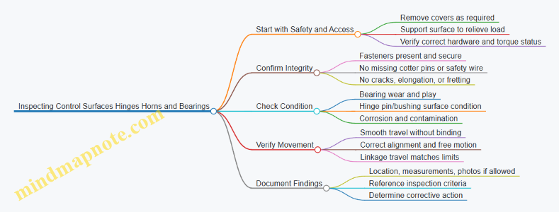
Step 1: Prepare for Inspection Without Creating False Problems
Support the control surface so hinge loads are not fighting your hands. If you inspect with the surface hanging, you can mask looseness or exaggerate it. Use the maintenance manual’s access instructions so you don’t skip hidden hinge areas.
Before looking closely, do a quick “hardware sweep.” Confirm the hinge line has all pins, bushings, washers, and retainers. Check that safetying devices are installed where required. A missing cotter pin is not a minor detail; it’s a direct path to fastener migration.
Example: The “Looks Tight” Fastener
A technician reports no obvious looseness at a flap hinge. During inspection, the cotter pin is missing, but the nut still feels snug. Under vibration, the nut can back off gradually. The correct action is to restore the required safetying and then re-check for any fretting or freeloop at the hinge.
Step 2: Inspect Hinges for Damage and Wear
Hinge inspection focuses on the hinge pin or bushing, the hinge knuckle surfaces, and the surrounding structure.
Look for:
- Cracks at hinge knuckles, around pin holes, and near attachment points.
- Elongation of pin holes or uneven wear patterns.
- Fretting corrosion, which often appears as dark, powdery residue where metal rubs.
- Evidence of binding, such as shiny spots only on one side of a bearing surface.
Use a light and, when allowed, a magnifier. If you can feel roughness by gently moving the surface by hand, that roughness is usually more than “just dry.” It can indicate contamination, corrosion, or bearing damage.
Example: Fretting That Tells You Where Motion Happened
On aileron hinges, you notice powdery residue concentrated near the lower knuckle. That pattern suggests micro-movement under load. Even if the hinge still moves, the wear location helps you target the cause—often insufficient lubrication, corrosion, or a slightly misaligned hinge line.
Step 3: Inspect Horns for Security, Alignment, and Condition
Horns connect the control surface to the linkage. Inspect the horn-to-pin or horn-to-bushing interfaces for:
- Cracks at the horn arms and around attachment holes.
- Elongated holes or worn bushings.
- Loose fasteners, missing washers, or incorrect hardware.
- Evidence of rubbing where the horn should not contact other parts.
Alignment matters because misalignment increases side loads on bearings and accelerates wear. When you move the control surface through its normal range, the horn should track without scraping.
Example: Scrape Marks That Point to Misalignment
A mechanic finds thin scrape marks on a horn near the outer range of travel. The hinge line looks intact, but the scrape repeats at the same position. That pattern often means the linkage geometry or installation is slightly off, creating contact only at certain deflections.
Step 4: Inspect Bearings for Play and Smoothness
Bearings can be bushings, roller bearings, or other rotating elements depending on the aircraft. The inspection goal is to detect excessive play, rough rotation, or contamination.
Check for:
- Excessive free play at the hinge line or horn interface.
- Roughness when rotating by hand (no grinding, no sticking).
- Dryness or contamination around bearing areas.
- Corrosion on bearing surfaces or in grease channels.
If the design includes lubrication, verify that grease fittings are present and that lubrication is consistent with the maintenance manual. Over-greasing can also cause mess and contamination, so follow the specified method.
Example: Play That Changes with Support
When the surface is supported, hinge play feels minimal. When the surface is allowed to hang, play increases. That behavior can indicate a bearing or bushing that is not carrying load evenly, or a hinge line that is slightly misaligned. Document the condition and verify with the manual’s inspection criteria.
Step 5: Verify Movement and Functional Integration
After visual checks, confirm the control surface moves smoothly through its normal range. Watch for binding, uneven resistance, or sudden “steps” that can indicate a damaged bearing or a hinge pin issue.
Also verify that the linkage travel corresponds to expected movement. If the horn moves but the surface response is inconsistent, the issue may be in the hinge line, the bearing, or the linkage connection.
Step 6: Document Findings Clearly Enough to Act
Record the location, what you observed, and any measurements required by the inspection criteria. If you find fretting, corrosion, cracks, or wear patterns, note the specific hinge or horn area and the direction of wear.
Example: A Useful Note
“Left aileron inner hinge: dark fretting residue at lower knuckle; slight roughness felt during hand movement; no missing hardware observed. Measure hinge pin/bushing wear per criteria and inspect adjacent knuckles for matching wear.”
Quick Checklist for the Exam
- Hardware present and safetying installed where required
- No cracks, elongation, or fretting corrosion
- Horn holes and attachment interfaces show no wear beyond limits
- Bearings rotate smoothly with no binding or grinding
- No scrape contact during normal range of motion
- Findings documented with location and measurements as required
4.5 Performing Rigging Checks and Control Travel Verification
Rigging checks confirm that control surfaces move the right amount, in the right direction, with the right mechanical advantage. Control travel verification confirms the movement matches the aircraft’s approved limits. Think of rigging as the “how,” and travel as the “how far.” Both must agree.
Foundational Concepts for Rigging and Travel
Start by identifying the control system type: cable-and-pulley, push-pull rod, or mixed. Each type has different failure modes. Cable systems can stretch or slip; rod systems can bind or misalign; mixed systems can hide issues at transition points.
Next, confirm the aircraft configuration. Control travel limits depend on weight and setup only in limited ways, but rigging is sensitive to how the aircraft is positioned. Use the maintenance manual’s specified control surface positions, reference points, and whether the aircraft must be chocked and secured. A common mistake is verifying travel with the control locked in a non-neutral position, which can mask a binding condition.
Finally, understand what “correct” looks like. Correct rigging produces smooth, consistent movement through the full range without abnormal resistance, slack, or uneven linkage motion. Correct travel produces measured deflection within the specified limits, typically with tolerances and sometimes with different limits for each surface.
Rigging Checks Before Measuring Travel
Begin with a visual and tactile sweep.
- Check linkage security: cotter pins, safety wire, locknuts, and correct hardware orientation.
- Check for free play: small amounts may be acceptable, but excessive slack can cause delayed control response.
- Check alignment: control horns, bellcranks, and pushrod ends should sit squarely in their attachment points.
- Check for interference: ensure nothing contacts adjacent structure through full motion.
- Check for lubrication and condition: dry bearings or contaminated joints can create friction that changes measured travel.
Example: If aileron travel is short, don’t jump straight to “adjust the stop.” First, verify that the pushrod ends are fully seated and that the rod end bearings rotate freely by hand. If one bearing feels gritty, the system may reach the stop early because friction increases under load.
Control Travel Verification Method
Use the approved measurement method and tools. Common tools include a protractor or calibrated angle gauge for angular deflection, and a ruler or tape for linear travel where the manual specifies it.
- Establish neutral reference. Set the cockpit controls to the neutral position specified by the manual.
- Verify surface alignment at neutral. The control surface should align with its reference marks without pulling against the linkage.
- Measure full travel in each direction. Move the control smoothly to the stop or to the measured limit method specified.
- Record results with units and direction. Note left/right or up/down and the measured value.
- Compare to limits. If out of tolerance, determine whether the issue is rigging (linkage geometry, stops, or adjustment) or a binding/friction problem.
A practical rule: if travel is short and the linkage feels stiff near the end of travel, suspect binding or friction before adjusting stops. If travel is short and movement is smooth, suspect rigging geometry or stop settings.
Adjustment Logic and Verification Loop
Adjustments should be targeted and reversible. Typical adjustment points include turnbuckles, rod end seating, stop bolts, and sometimes cable tension. Make one change at a time, then re-check both rigging condition and travel.
Example: Elevator travel is within limits, but the linkage shows uneven motion between bellcrank arms. That can indicate misalignment or a partially seated rod end. Correct the mechanical seating first, then re-measure travel to ensure the fix didn’t shift the neutral or change the effective ratio.
Mind Map: Rigging Checks and Control Travel Verification
Common Pitfalls and How to Avoid Them
- Measuring with controls not truly neutral: neutral must match the manual’s reference, not “eyeballed center.”
- Confusing stop contact with correct travel: stops are part of the system, but binding can cause early stop contact.
- Adjusting without checking hardware seating: a mis-seated rod end can produce correct-looking travel while still creating a future wear problem.
- Skipping interference checks: a clearance issue might only appear at the extremes, so verify the full range.
Example Workflow for aileron Rigging and Travel
Set cockpit aileron controls to neutral. Confirm aileron neutral alignment with reference marks. Move the aileron to full up and measure deflection with the specified gauge. Repeat for full down. If up travel is short but down travel is normal, inspect the linkage for binding on the upward arc and verify stop settings for that direction. Correct the mechanical cause, then re-measure both directions to confirm the adjustment didn’t shift the other side.
When rigging checks and travel verification agree, the control system is not just “in spec,” it’s also mechanically consistent—meaning it should stay that way as the aircraft is operated and inspected over time.
5. Aircraft Electrical Fundamentals and Wiring Practices
5.1 Understanding Aircraft Electrical Power Sources and Distribution
Aircraft electrical systems exist to do two jobs: provide power to equipment and keep that power within safe limits. On the exam, you’ll often be asked to identify which source feeds which bus, what protects the circuit, and what happens when a component fails. The trick is to think in layers: generation, conversion, distribution, and protection.
Core Power Sources
Most aircraft use a combination of engine-driven generators and a backup source. The primary source is typically an engine-driven generator that produces AC power. A battery provides DC power for starting and for essential loads when the generator is offline. Some aircraft also include an external power receptacle for ground operations.
A simple way to remember the roles:
- Battery: “small and ready now,” especially for starting.
- Generator: “steady and capable,” once the engine is running.
- External power: “ground-only convenience,” feeding the system without draining the battery.
Power Conversion and Rectification
Even if the generator produces AC, many aircraft loads need DC. Rectifiers convert AC to DC, and regulators keep voltage within limits. If you see terms like “rectifier” and “regulator” in a question, assume the system is managing conversion and stability rather than distribution.
Example: During normal operation, the generator output is rectified to supply a DC bus. If the regulator fails high, overvoltage protection should open or limit the affected path so sensitive avionics don’t get cooked.
Distribution Architecture
Distribution is usually organized into buses. A bus is a common connection point that lets multiple loads share the same source while still allowing isolation. Common bus types include:
- AC bus for AC loads.
- DC bus for DC loads.
- Essential or standby buses for critical equipment.
Switching devices route power from sources to buses. Typical components include contactors and bus ties. A bus tie can connect two buses under controlled conditions, but it’s not meant to be a “free-for-all.” It exists so you can restore power to a bus without backfeeding faults.
Protection and Isolation
Protection keeps faults from turning into smoke. The main tools are circuit breakers, fuses, and protective relays.
- Circuit breakers: resettable overcurrent protection.
- Fuses: one-time protection.
- Relays: control logic for switching and fault response.
A key exam concept is selective protection: the protection closest to the fault should open first. If a downstream breaker trips, upstream devices should remain closed, limiting the number of loads affected.
Example: A short circuit occurs on a single avionics rack. The rack’s breaker trips, removing power from that rack while the rest of the DC bus stays energized.
Ground and In-Flight Operating Logic
On the ground, external power may feed the buses while the battery supports essential circuits. In flight, the generator becomes the primary source. Many systems include logic that prevents the battery from being charged/discharged in unsafe ways and prevents backfeeding a failed generator.
Example: If a generator fails, the system should transfer essential loads to the standby path or battery-backed bus, depending on the aircraft design. The question usually expects you to identify that the battery is not the main source for everything, but it can keep critical systems alive.
Mind Map: Aircraft Electrical Power Sources and Distribution
Quick Scenario Checks
-
Question style: “Which component converts AC generator output to DC for avionics?”
- Answer: rectifier (with regulator controlling voltage).
-
Question style: “A short occurs on one load. What should happen to minimize impact?”
- Answer: the nearest breaker or fuse trips, leaving other loads on the bus powered.
-
Question style: “Why use a bus tie instead of permanently connecting buses?”
- Answer: controlled connection prevents faults or failed sources from backfeeding into the other bus.
By treating the system as a chain—source to conversion to bus distribution to protection—you can answer most exam questions without guessing. The wording may vary, but the logic stays consistent.
5.2 Interpreting Wire Types Connectors and Terminal Markings
Aircraft wiring is a chain of small, specific decisions: the wire type must match the environment, the connector must match the mating hardware, and the terminal marking must match the intended circuit. When any link is wrong, the symptoms range from intermittent faults to heat damage—often without warning. This section builds a practical way to interpret what you see on the aircraft and what the markings are trying to tell you.
Wire Types You Can Identify by Construction
Start with the wire’s job: power, signal, lighting, or high-temperature/engine-area service. Then confirm by construction clues.
- Conductor material and size: Markings often include gauge or cross-sectional area. A smaller conductor can’t safely carry the same current as a larger one.
- Insulation type: Look for printed codes or jacket markings that indicate temperature rating and chemical resistance. In engine compartments, insulation must tolerate heat and fluids.
- Shielding and twist: Shielded or twisted pairs are common for signal integrity. If you see shielding, you should expect a connector and termination method that preserves that shield continuity.
- Overall jacket: Some harnesses use a protective outer jacket. If the jacket is missing or damaged, the wire may no longer meet the original environmental protection.
Example: You find a two-conductor wire labeled for high-temperature use in an engine bay. The insulation marking matches the expected temperature class, and the conductor size matches the circuit current requirement. That alignment supports both electrical safety and durability.
Connector Types and How to Match Them
Connectors are not interchangeable “plug shapes.” They are designed around contact style, locking method, and pin or socket geometry.
- Contact style: Pin vs. socket matters. A pin contact cannot reliably mate with a socket contact without the correct mating assembly.
- Series and shell size: Many connectors share a similar look, but different series use different keying and contact arrangements.
- Keying and polarization: Keyways and shrouds prevent incorrect mating. If a connector is mis-keyed or forced, the fault is usually mechanical, not electrical.
- Locking method: Tabs, latches, or threaded coupling determine retention. A loose connector can create intermittent opens under vibration.
Example: A connector with a keyed shroud prevents mating in the wrong orientation. If someone “fixes” an alignment issue by trimming or bending keying features, the connector may still mate but will no longer guarantee correct contact pairing.
Terminal Markings That Tell You the Circuit Story
Terminal markings are the aircraft’s shorthand for “what this connection is supposed to be.” Interpret them in layers.
- Manufacturer or part identifier: Confirms the terminal’s design family.
- Wire size compatibility: Many terminals are rated for specific conductor ranges. Using the wrong terminal can cause poor crimp quality.
- Insulation support and contact area: Some terminals crimp onto insulation for strain relief; others rely on conductor-only crimping. The terminal marking indicates which method is intended.
- Plating and corrosion resistance: Contact plating affects reliability in moisture-prone areas.
Example: A terminal marked for a specific conductor range is installed on a wire that is slightly larger. The crimp may look “tight,” but the contact area may not compress correctly, leading to higher resistance and heat under load.
Practical Interpretation Workflow
Use a repeatable sequence so you don’t rely on memory.
- Read the wire jacket or print: Capture wire type, temperature class, and size.
- Identify the connector family: Confirm keying, shell style, and contact type.
- Check terminal markings: Verify conductor range and crimp type.
- Inspect the termination quality: Look for correct crimp height, insulation support engagement, and no conductor strands outside the crimp.
- Confirm continuity and grounding: After physical verification, electrical checks confirm the mechanical story.
Example: A harness shows correct wire markings and connector keying, but the terminal marking indicates a different conductor range. The physical mismatch explains a later intermittent fault when the wire flexes.
Mind Map: Wire Types Connectors and Terminal Markings
Common Mistakes and How to Spot Them
- Wrong terminal on correct wire: The wire may be fine, but the terminal marking doesn’t match the conductor range.
- Correct terminal, wrong connector: The terminal may fit the contact, but the connector series may not preserve proper alignment or retention.
- Shield broken at the wrong point: Shielded wiring requires a termination method that maintains shield continuity; otherwise, noise can masquerade as a “mystery” fault.
- Forced mating: If keying doesn’t align, stop. Forcing usually damages contacts or changes contact pressure.
Example: A shielded pair is terminated with an unshielded style terminal. The harness passes a quick visual check, but later the signal shows noise spikes when adjacent loads switch.
Quick Check Example for Exam Style Questions
You’re given a scenario: a wire labeled for high-temperature service is connected to a keyed connector, but the terminal marking indicates a smaller conductor range. The best interpretation is that the termination is not compliant with the intended crimp geometry. Even if the connector mates, the crimp quality and contact resistance can be compromised, making intermittent operation likely.
5.3 Inspecting Wiring for Chafing Heat Damage and Corrosion
Wiring inspection is mostly pattern recognition plus verification. Chafing, heat damage, and corrosion often start small, but they change insulation, shielding, and connector integrity in ways that show up under light, touch, and measurement.
Foundational Concepts You Must Tie Together
Start by separating three failure modes:
- Chafing is mechanical abrasion from vibration, movement, or poor routing. It usually appears as worn insulation, exposed conductor strands, or shiny rub marks.
- Heat damage is insulation degradation from excess temperature, poor contact, or restricted airflow. It often shows as hardening, discoloration, brittleness, or a melted jacket.
- Corrosion is chemical or electrolytic attack. It typically shows as green/white residue, pitting, dark fretting, or increased resistance at terminals.
A practical rule: mechanical damage changes the insulation surface, thermal damage changes the insulation material, and corrosion changes the metal interface. Your inspection should look for evidence that matches the rule.
Mind Map: Wiring Damage Signals and Checks
Step-by-Step Inspection Flow
Prepare the Area and Establish a Baseline
Use the wiring diagram and aircraft maintenance manual guidance to identify the circuit and expected routing. Then inspect the entire run, not just the suspected spot. A chafe point often starts near a clamp, grommet, or bundle tie where movement concentrates.
Example: If a wire bundle passes near a sharp edge, you may find the worst wear at the first contact point. The surrounding insulation might look fine, but the abrasion pattern usually shows a gradient—slight scuffing leading to deeper wear.
Inspect for Chafing Along Routing and Interfaces
Look for rub marks, flattened insulation, and any area where the jacket looks thinner. Pay special attention to:
- Where wires pass through structure using grommets or bulkhead fittings
- Where bundles are secured with clamps or ties
- Where harnesses meet connectors and backshells
Easy check: run a gloved finger lightly along the harness. You are not trying to “feel damage,” you are checking for sharp transitions like a ridge where insulation has been worn through.
Inspect for Heat Damage at Terminals and Junctions
Heat damage is often concentrated at connectors, splices, and any location with a history of intermittent operation. Inspect for discoloration, blistering, or a hardened, cracked jacket.
Example: A connector that was reassembled with insufficient seating can create a small resistance increase. Over time, that resistance heats the terminal interface, and the insulation near the backshell shows a darker band compared to the rest of the wire.
If the manual requires electrical checks, verify continuity, resistance, or insulation resistance using the specified method. Visual evidence without verification can miss a “good-looking” insulation that has degraded internally.
Inspect for Corrosion at Metal Interfaces and Seals
Corrosion is frequently found where moisture can collect: backshell seams, drain paths, and areas near condensation sources. Inspect for residue, pitting, and looseness.
Example: Green residue on a terminal pin often indicates moisture exposure. Even if the wire insulation looks intact, corrosion can increase resistance and cause heat at the same location you are inspecting.
Confirm Corrective Readiness
When you find damage, confirm whether the repair method requires replacement, splice, or re-termination. Also verify that the root cause is addressed: missing clamps for chafing, proper connector seating for heat, and seal integrity for corrosion.
Quick Decision Guide
- Worn insulation with rub marks → treat as chafing and verify routing, clamps, and grommets.
- Discolored or brittle insulation near a connector → treat as heat and verify connector seating and circuit protection.
- Residue or pitting at terminals → treat as corrosion and verify sealing and terminal condition.
Case Example: One Harness, Three Clues
A technician finds a wire bundle near a bulkhead with scuffed insulation and a connector backshell with white residue. The scuffing points to chafing from bundle movement, while the residue suggests moisture ingress at the backshell seal. After replacing the damaged section, the technician re-clamps the harness to remove motion and reseats the connector with the correct locking method. The reinspection focuses on both the repaired area and the adjacent routing, because the original problem rarely stays in one place.
5.4 Applying Proper Grounding Bonding and Shielding Practices
Grounding, bonding, and shielding are the “boring” parts of aircraft electrical work that keep everything from turning into a noisy, unreliable mess. The goal is simple: give electrical faults a predictable path, keep voltage differences where they belong, and prevent unwanted signals from hitchhiking along wiring.
Foundational Concepts and Why They Matter
Grounding ties a system to the aircraft structure or a designated reference point so voltages have a stable reference. Bonding connects conductive parts together so they share the same electrical potential. Shielding uses a conductive barrier around a wire or cable to reduce coupling from external electromagnetic fields.
A practical way to remember the difference: grounding sets the reference, bonding equalizes potentials between parts, and shielding blocks interference from reaching the signal.
Grounding Practices That Hold Up Under Inspection
Start with the grounding points specified in the wiring diagram and maintenance manual. Use the correct lug type, ring terminal, and hardware, and ensure the connection surfaces are clean and conductive.
A common mistake is assuming “painted metal is fine because it’s still metal.” Paint and anodizing can add resistance. If the manual calls for a bonding jumper or a specific ground point, follow it exactly. When a ground strap is required, treat it like a component: correct length, correct routing, and correct termination.
Example: If a tail strobe circuit shows intermittent operation, inspect the ground termination at the light housing. A loose or corroded ground lug can create a voltage drop that only appears when vibration or current draw increases.
Bonding Practices for Equal Potential Across the Airframe
Bonding is about preventing dangerous or annoying voltage differences between adjacent conductive parts. Bond straps and bonding jumpers should be installed where the design expects them, such as between engine components and the airframe, between panels, and across joints.
Inspect bonding points for:
- Continuity: no open circuits due to missing straps or broken wires.
- Security: hardware properly torqued and safetyed.
- Surface condition: corrosion, paint, or oxidation that increases resistance.
- Mechanical integrity: straps not stretched, rubbing, or routed where they can be damaged.
Example: A bonding jumper between a control surface and the fuselage can be overlooked during panel removal. After reassembly, a missing strap may not cause immediate failure, but it can increase susceptibility to noise and create intermittent faults.
Shielding Practices for Signal Integrity
Shielding reduces interference coupling into signal conductors. The shield must be terminated correctly; a floating shield can behave like an antenna.
Key rules:
- Terminate the shield to the specified bonding/ground point.
- Maintain the shield’s continuity through connectors using the correct backshell or shield clamp.
- Avoid cutting the shield short unless the design explicitly allows it.
Example: Consider a low-level sensor wire routed near a high-current feeder. If the shield is terminated only at one end when the design expects both ends, the sensor may show erratic readings during electrical load changes.
Systematic Inspection Workflow for Grounding, Bonding, and Shielding
Use a repeatable approach that matches how exam questions are written.
- Identify the circuit intent: power, return path, or signal.
- Locate the specified reference points: grounding and bonding locations from the wiring diagram.
- Verify physical installation: correct hardware, routing, and termination.
- Check surface readiness: remove corrosion and ensure conductive contact where required.
- Confirm shield termination: correct clamps, backshells, and continuity.
- Assess mechanical risk: strain relief, chafing protection, and secure routing.
Common Failure Modes and How to Spot Them
- Corrosion at terminations increases resistance, causing voltage drops and intermittent behavior.
- Loose hardware can work itself out under vibration, especially after repeated access.
- Incorrect ground point selection leads to return currents flowing through unintended paths.
- Shield breaks at connectors create intermittent noise that tracks with connector movement.
Mind Map: Grounding Bonding and Shielding
Example: Applying the Workflow to a Noisy Indicator
Suppose an engine indicator shows flicker when landing gear is operated. Follow the workflow: confirm whether the indicator is a signal or power circuit, then check the indicator ground termination and any bonding straps near the instrument panel. Next, inspect the shielded wiring for correct termination at both the connector backshell and the specified ground point. Finally, verify that no bonding jumper was omitted during recent access to the panel or nearby equipment. This sequence narrows the cause from “mystery noise” to a specific grounding, bonding, or shielding issue you can correct with confidence.
5.5 Verifying Circuit Protection and Correct Component Substitution
Circuit protection is the part of an aircraft electrical system that quietly does its job until it doesn’t. On the exam, the key is not memorizing part numbers—it’s verifying that the protection device matches the circuit’s design intent and that any substitution preserves electrical and installation characteristics.
Foundational Concepts You Must Tie Together
Start with the purpose of protection: protect wiring, connectors, and downstream components from excessive current and faults. A fuse or circuit breaker is selected so it opens or trips within a defined current range, without nuisance operation during normal loads.
Next, connect protection to the circuit’s load profile. If a circuit draws a steady current, the protection must tolerate that steady draw. If a circuit has inrush or transient behavior, the protection must tolerate short-duration peaks without opening.
Finally, connect protection to the installation environment. A breaker’s trip curve, a fuse’s time-current characteristic, and the physical mounting and wiring practices all affect whether the device will behave as designed.
What to Verify During Inspection
-
Correct device type and rating: Confirm the protection device is the specified type (fuse vs breaker) and that its rating matches the approved data for the circuit.
- Example: If a circuit is protected by a 5 A fuse, replacing it with a 10 A fuse may keep the circuit working during a fault, but it also allows more current to flow through wiring than the design intended.
-
Correct location and labeling: Verify the device is in the correct panel position and that the circuit identification matches the wiring diagram.
- Example: A mechanic swaps two identical-looking breakers in adjacent slots. The aircraft powers up, but a fault now protects the wrong circuit.
-
Condition and integrity: Inspect for signs of overheating, loose terminals, corrosion at the device leads, and evidence of prior arcing.
- Example: A breaker that trips repeatedly may show discoloration at the terminal. That’s a clue to check the connector torque and contact condition, not just reset the breaker.
-
Wiring compatibility: Confirm the wire gauge and insulation type are correct for the circuit and that terminations are properly crimped or installed.
- Example: A circuit originally wired with smaller-gauge wire might “work” with a higher-rated fuse, but it violates the protection coordination concept.
Correct Component Substitution Logic
When substitution is allowed, it must be “like for like” in the ways that matter electrically and mechanically.
-
Electrical equivalence: The replacement must match the protection characteristic. For fuses, the time-current curve matters; for breakers, the trip curve matters.
- Example: Replacing a fast-acting fuse with a slow-blow fuse can delay clearing during a fault, increasing damage risk.
-
Physical and installation equivalence: The replacement must fit the mounting, terminal style, and panel layout. Incorrect fit can lead to poor contact or strain on the wiring.
- Example: A fuse holder designed for a specific cartridge length won’t clamp properly with a different cartridge style.
-
Environmental and system compatibility: Some devices are rated for specific temperatures, voltages, or interrupting capacities.
- Example: A breaker with insufficient interrupting capacity may not clear a high-current fault safely.
Mind Map: Circuit Protection Verification
Practical Example Walkthrough
A technician finds a blown fuse in an avionics power circuit. The fuse body markings show it is rated 2 A, but the replacement installed during maintenance is unmarked.
- First, verify the circuit’s approved data for the correct fuse type and rating.
- Second, inspect the fuse holder and terminals for overheating or looseness. A blown fuse can be caused by a fault downstream, not just a “bad fuse.”
- Third, install only the correct approved replacement. If the approved data calls for a specific fuse type with a particular time-current characteristic, do not substitute a different style even if the amperage matches.
The exam often tests the reasoning: “If it works, it’s fine” is not the standard. The standard is whether the protection device will clear faults as designed, while preserving wiring and connector safety.
Common Exam Traps to Avoid
- Matching amperage only: Rating alone is not enough; the characteristic matters.
- Ignoring terminal condition: A new fuse on a damaged terminal can fail again quickly.
- Assuming identical appearance means identical function: Two devices can look the same but have different trip behavior or interrupting capacity.
Quick Checklist for Test Answers
- Confirm correct protection device type and rating from approved data.
- Confirm correct characteristic behavior for the circuit.
- Verify correct panel location and circuit identification.
- Inspect terminals, connectors, and wiring condition.
- Substitute only with like-for-like electrical and mechanical compatibility.
6. Aircraft Instruments and Indicating Systems
6.1 Understanding Pitot Static Systems and Instrument Inputs
A pitot-static system measures air pressure and turns it into instrument readings. The key idea is simple: the system creates pressure signals from the airflow, then instruments convert those signals into values you can use—airspeed, altitude, and vertical speed. If you keep track of which pressure goes where, most exam questions stop feeling mysterious.
Core Pressure Sources and What They Mean
A pitot tube faces the oncoming airflow and captures impact pressure. Static ports sense static pressure, which represents the ambient air pressure around the aircraft. Instruments don’t “read air” directly; they read pressure differences.
- Airspeed indicator uses the difference between impact and static pressure.
- Altimeter uses static pressure referenced to a standard atmosphere.
- Vertical speed indicator uses static pressure changes over time.
A practical way to remember this: if the instrument needs “how fast,” it usually needs a pressure difference; if it needs “where you are,” it usually needs static pressure.
System Layout from Tubes to Instruments
Most aircraft route pitot and static pressures through tubing to the instrument panel. The pitot line carries impact pressure; the static line carries static pressure. Many systems include:
- Drain provisions to remove moisture from low points.
- Anti-ice or heated pitot on aircraft equipped for icing conditions.
- Filters or screens in some designs to reduce contamination.
- Multiple static sources to improve reliability and reduce error from local airflow.
A common exam trap is mixing up pitot and static lines. If the question mentions “airflow direction” or “impact,” think pitot. If it mentions “ambient pressure” or “altitude,” think static.
Instrument Input Conversion Logic
Airspeed Indicator
The airspeed indicator measures dynamic pressure (impact minus static). The instrument movement and calibration account for how dynamic pressure relates to true airspeed. In other words, the same pressure difference corresponds to different speeds depending on air density.
Example: If the static ports are blocked, static pressure becomes artificially high or low depending on airflow effects at the blockage point. The airspeed indicator then shows incorrect speed because the pressure difference is wrong.
Altimeter
The altimeter uses static pressure only. It compares the measured static pressure to a standard pressure-altitude relationship. That’s why altimeter settings matter: you’re adjusting the reference so the instrument’s “standard atmosphere” matches local conditions.
Example: If you set the wrong altimeter setting, the altimeter still responds correctly to static pressure changes, but the displayed altitude is offset.
Vertical Speed Indicator
The vertical speed indicator uses static pressure and a delay mechanism. The instrument compares the instantaneous static pressure to a filtered version of that pressure. The difference over time becomes a rate indication.
Example: If a static leak exists, the VSI may respond sluggishly or erratically because the pressure change rate reaching the instrument is altered.
Common Failure Modes and Their Instrument Effects
Understanding failure modes is where the system becomes exam-friendly.
- Blocked pitot: Airspeed indicator becomes unreliable because impact pressure is missing.
- Blocked static: Airspeed, altimeter, and vertical speed can all become unreliable because static pressure is wrong.
- Leaking static line: Instruments may show abnormal behavior, often with delayed or inconsistent readings.
- Water or ice in lines: Can cause intermittent errors, especially after temperature changes.
A quick rule: if static pressure is compromised, multiple instruments suffer because they all depend on static input.
Mind Map: Pitot Static System and Instrument Inputs
Example: Mapping a Pressure Problem to the Correct Instrument
Suppose an aircraft has a suspected static port blockage. The airspeed indicator will likely show incorrect speed because its pressure difference uses static pressure. The altimeter will show incorrect altitude because it depends on static pressure directly. The vertical speed indicator will likely behave oddly because it depends on changes in static pressure.
Now compare that to a blocked pitot: only the airspeed indicator is directly affected because the altimeter and VSI do not need impact pressure.
Key Takeaways for Exam Questions
- Pitot equals impact pressure; static equals ambient pressure.
- Airspeed uses pressure difference; altimeter and VSI use static pressure.
- Static failures affect multiple instruments; pitot failures mostly affect airspeed.
- Vertical speed is about how static pressure changes, not just the value.
6.2 Inspecting Vacuum Systems and Associated Components
A vacuum system on many aircraft provides suction for instruments such as attitude indicators and directional gyros. The goal of inspection is simple: confirm the system can produce stable vacuum, deliver it to the instruments without leaks or contamination, and keep the mechanical parts operating within limits. Think of it like plumbing plus a precision instrument feed—if either side is wrong, the gauge will eventually tell on you.
Foundational Concepts You Must Know
Vacuum is created by an engine-driven pump. That pump draws air through a filter and routes it through a regulator and relief components before sending suction to the instrument inlets. A typical system includes:
- Vacuum pump and mounting hardware
- Filter and screen elements
- Vacuum regulator and relief valve
- Hoses and fittings
- Vacuum gauge and/or indicator
- Instrument vacuum inlet and internal passages
- Seals, O-rings, and gaskets at connections
A key inspection idea is that vacuum systems fail in two broad ways: they cannot make enough suction, or they cannot keep it. Low suction points toward pump output, regulator settings, or a restricted filter. Poor retention points toward leaks, loose fittings, cracked hoses, or worn seals.
Systematic Inspection Flow
Visual and Installation Checks
Start with the easy wins: look for obvious damage before you measure anything. Check hose routing for chafing, kinks, and contact with sharp edges. Verify clamps and fittings are secure and correctly oriented. Inspect the pump area for oil contamination around seals, because oil ingestion can reduce suction performance and foul instrument internals.
Example: If a hose is routed near a moving control cable, you may see shiny wear marks. Even a small abrasion can become a leak path under vibration.
Filter Condition and Restriction Clues
Inspect the vacuum filter for clogging, missing elements, or improper installation. A restricted filter often shows up as sluggish vacuum response or consistently low readings.
Example: During a ground check, the vacuum gauge rises slowly and never reaches the expected range. A clogged filter is a common culprit because it limits airflow to the pump.
Regulator and Relief Valve Operation
The regulator controls suction level so the instruments receive a consistent supply. Inspect for correct attachment, secure safety wiring where applicable, and signs of sticking or contamination. If the system includes an adjustable regulator, confirm the setting method matches the maintenance manual procedure.
Example: If vacuum is high enough to cause excessive instrument indications or abnormal wear, the regulator may be stuck or misadjusted.
Hose Integrity and Connection Sealing
Check hoses for cracks, hardening, loose ends, and loose clamps. Inspect fittings for corrosion and verify that sealing surfaces are clean and undamaged. Replace suspect O-rings or gaskets rather than “hoping it seals.”
Example: A fitting that was previously reassembled with a nicked O-ring can leak only under certain engine power settings. That’s why a leak can be intermittent and harder to diagnose.
Vacuum Gauge Verification
Confirm the gauge is readable, properly connected, and not physically damaged. If the aircraft uses a test port or known reference procedure, follow it to verify gauge accuracy. A correct gauge matters because you can’t troubleshoot what you can’t trust.
Example: If the gauge reads low but the instrument appears normal, the gauge or its connection may be the issue rather than the pump.
Instrument Inlet and Internal Passage Considerations
Inspect the instrument vacuum inlet for secure attachment and clean condition. Avoid introducing debris when disconnecting hoses. If the instrument has a filter or screen at the inlet, check it per the maintenance manual.
Example: A small piece of hose liner or dirt introduced during service can block the inlet and cause erratic instrument behavior.
Common Failure Patterns and What They Suggest
- Low vacuum across all power settings: filter restriction, pump output problem, regulator stuck, or major leak.
- Vacuum drops after a period of operation: hose clamp loosening, seal degradation, or a leak that opens under vibration.
- Vacuum fluctuates rapidly: unstable regulator, air ingestion, or intermittent hose connection.
Mind Map: Vacuum System Inspection Logic
Practical Example: Turning Observations into Actions
You observe low vacuum during a ground run. The hose routing looks intact, and the pump area is clean. The filter is found heavily discolored and partially blocked. After replacing the filter element and confirming correct installation, vacuum returns to the expected range and remains stable. The reasoning chain is straightforward: restriction reduces airflow to the pump, which reduces suction delivered to the instruments.
Practical Example: Leak That Only Shows Up Sometimes
After a hose replacement, vacuum readings are normal at idle but drop at higher power. The hose appears secure, yet one clamp shows slight misalignment and the O-ring has a visible nick. Replacing the O-ring and reseating the fitting restores stable vacuum. The lesson is that small sealing defects can behave like “it works until it doesn’t,” especially under vibration and pressure changes.
6.3 Checking Electrical Engine Indicating Systems and Sensors
Electrical engine indicating systems translate sensor signals into readable cockpit indications and, in many aircraft, into annunciations. Your job during inspection is to confirm the system is wired correctly, powered correctly, calibrated correctly, and responding correctly—without guessing. Start with the big picture, then verify each link in the chain.
Foundational Concepts You Must Keep Straight
Most engine indications come from a sensor, a signal conditioning path, and a display or indicator. The sensor may be thermocouple, RTD, strain gauge, Hall-effect, or a pressure transducer. The signal path may be analog (voltage/current) or digital (serial data), but the inspection logic is the same: confirm the input is plausible, the conversion is correct, and the output matches the aircraft’s expected behavior.
A practical way to think about it is “power, ground, signal, and interpretation.” If an oil temperature gauge reads cold while the engine is clearly warm, you don’t start by blaming the gauge. You check power and ground to the sensor and indicator first, then the signal path, then the display.
System Map of What You Are Checking
Mind Map: Electrical Engine Indicating System Checks
Step-by-Step Inspection Flow
Confirm Indicator and Sensor Power Sources
Begin by identifying which indications are powered by the same bus or system. If multiple gauges share a common feed, a single bus issue can explain several “dead” indications. For example, if oil pressure and fuel pressure both read zero while other electrical systems are normal, you check the specific indicator power feed and its circuit protection before touching sensor wiring.
Look for obvious issues: loose circuit breaker, damaged breaker label, missing fuse, or a connector that looks like it was installed in a hurry. Then verify with the appropriate test method for the aircraft: voltage checks at the indicator and at the sensor connector.
Verify Grounds and Shielding
Many engine sensor circuits rely on a stable ground reference. A corroded ground lug can create intermittent readings that “fix themselves” after vibration or temperature changes. Inspect ground points for corrosion, paint under the lug, and looseness.
If the system uses shielded wiring, confirm the shield termination is intact at the correct end. A shield that’s floating can turn a sensor circuit into an antenna. Example: a tach-related indication that jitters only when certain avionics are powered often points to grounding or shielding problems rather than the tach sensor itself.
Inspect Wiring and Connectors Like You Mean It
Use a structured visual inspection: routing, abrasion points, heat exposure near exhaust components, and connector pin condition. Then perform continuity and resistance checks as required by the maintenance manual.
Example: if an exhaust heat sensor circuit shows intermittent open readings, inspect the harness where it passes near a cowl hinge or where it could rub during engine movement. A tiny nick can become an open circuit under load.
Check Sensor Output Plausibility
Sensor checks depend on sensor type.
- Temperature sensors: verify correct wiring polarity and expected resistance/voltage behavior at known conditions. RTDs typically show resistance changes with temperature; thermocouples generate small voltages that vary with temperature.
- Pressure sensors: confirm the sensor is receiving the correct excitation (if applicable) and that the output changes smoothly with pressure.
- Speed/position sensors: verify signal presence and correct waveform characteristics when the aircraft procedures allow.
Example: if an oil temperature indication is stuck at a fixed value, the sensor could be open, shorted, or the signal path could be shorted to ground. A quick resistance/continuity check across the sensor circuit often narrows the fault faster than repeatedly cycling the system.
Verify Indicator Response and Calibration Behavior
Indicators can fail even when the sensor is fine. For analog gauges, confirm the needle movement is smooth and returns correctly when the input changes. For digital readouts, confirm the system updates as expected and that any self-test or built-in test behavior is normal.
Example: a gauge that moves in the correct direction but is consistently offset suggests calibration or scaling issues. A gauge that jumps erratically suggests intermittent wiring, poor ground, or a failing sensor connection.
Validate Annunciations and Limits
Many engine indications have associated warning thresholds. Check that annunciations correspond to the correct sensor and that the warning logic is consistent with the aircraft’s configuration.
Example: if the oil pressure warning light never illuminates during a controlled test where it should, treat it as a wiring or logic issue first, not as “the light is probably fine.” Confirm the sensor signal reaches the warning circuit.
Common Fault Patterns and How to Confirm Them
- Multiple indications dead together: suspect shared power feed or common ground.
- One indication erratic: suspect connector pin issues, chafing, or intermittent sensor output.
- Indication stuck at a limit: suspect open circuit (often reads low) or short to ground/power (often reads high), depending on the circuit design.
- Correct direction but wrong magnitude: suspect calibration/scaling, incorrect sensor type, or swapped wiring.
Documentation and Practical Test Notes
Record the exact indication behavior observed, including whether the fault is steady or intermittent. Note connector part numbers, wire routing observations, and the test values you measured. If you replace a sensor, verify the new installation matches the approved part and that the connector and wiring match the aircraft’s wiring diagram.
A good inspection ends with a coherent chain: “Power and ground verified, wiring integrity confirmed, sensor output plausible, indicator response correct, annunciations consistent.” If any link is missing, the system is not truly checked—only partially guessed.
6.4 Interpreting Primary Flight Instrument Indications During Inspection
Primary flight instruments translate system inputs into readable cues. During inspection, your job is not just to confirm the needle moves, but to confirm it moves correctly for the aircraft’s configuration and the inspection conditions.
Foundational Inputs and What They Mean
Start by mapping each primary instrument to its source:
- Airspeed indicator: pitot-static pressure difference.
- Attitude indicator: attitude reference (typically gyroscopic or electronic attitude reference).
- Altimeter: static pressure converted to altitude.
- Vertical speed indicator: rate of change of static pressure.
A practical rule: if two instruments share the same static source, their behavior should agree in direction and timing. For example, when you observe a change in altitude indication, the vertical speed should show a corresponding trend rather than contradict it.
Inspection Mindset and Setup
Before interpreting readings, confirm the basics that affect interpretation:
- Instrument power and mode: verify the correct power source is available and any required mode is selected.
- Static system condition: check for obvious blockage, leaks, or moisture contamination at accessible points.
- Mechanical freedom: ensure no binding or obvious damage to instrument faces, bezels, or mounting.
Example: If the altimeter is sluggish but the airspeed responds normally, the issue may be localized to the static side feeding the altimeter/vertical speed, not the pitot side.
Airspeed Indicator Interpretation
During inspection, interpret airspeed with attention to how it should respond to pressure changes:
- Normal response: smooth movement without hesitation.
- Common mismatch: airspeed that jumps quickly while altitude remains stable can indicate pitot-side issues.
- Stuck needle: often points to blockage, internal friction, or a pressure path problem.
Easy example: With the aircraft stationary, you should not see large airspeed changes. If the airspeed indicator climbs steadily while the aircraft remains still, suspect a pitot obstruction, a leak, or an instrument error.
Altimeter and Vertical Speed Interpretation
Altimeter interpretation focuses on static pressure conversion accuracy and stability:
- Altimeter drift: slow movement when conditions are unchanged suggests a static leak or instrument internal issue.
- Vertical speed lag: vertical speed should respond to changes in static pressure rate, not to unrelated instrument movement.
Easy example: If the altimeter shows a small change but the vertical speed stays at zero, the vertical speed mechanism may be sluggish or the static pressure change may be too small to register. If the vertical speed swings hard without altimeter movement, suspect a vertical speed plumbing or internal issue.
Attitude Indicator Interpretation
Attitude indicators are the “story” of aircraft orientation. During inspection, interpret them by checking consistency with known physical cues:
- Level reference: when the aircraft is on level ground and properly configured, the attitude indicator should show near-level pitch.
- Roll indication: small roll changes should correspond to actual aircraft roll.
Example: If the aircraft is visibly level but the attitude indicator shows a persistent nose-up attitude, check for installation issues, reference alignment, or power/reference problems depending on the system type.
Cross-Checks That Prevent False Conclusions
Use cross-check logic to avoid blaming the wrong instrument:
- Static-source pair check: altimeter and vertical speed should show related behavior during any controlled static pressure change.
- Pitot vs static separation: airspeed should not behave like altitude when only one pressure source is affected.
- Attitude independence: attitude should not “track” airspeed or altitude changes directly; it tracks orientation.
Mind Map: Primary Flight Instrument Interpretation
Common Interpretation Traps and How to Avoid Them
- Assuming “movement means good”: a needle can move while the pressure path is wrong. Confirm direction and stability.
- Ignoring time behavior: some instruments lag by design; others should respond promptly. Compare response timing across instruments.
- Over-trusting one instrument: one instrument can be wrong while others remain correct. Cross-check before concluding.
Quick Example Walkthrough
If you observe: altimeter stable, vertical speed near zero, and airspeed fluctuating slightly while the aircraft is stationary, the most likely area is the pitot-side path or airspeed instrument behavior. If instead altimeter drifts and vertical speed follows, focus on the static side feeding both instruments.
Interpreting primary flight instruments during inspection is basically disciplined pattern recognition: confirm inputs, observe behavior, then use cross-checks to narrow the cause without guessing.
6.5 Performing Functional Checks for Warning Annunciators and Alerts
Functional checks confirm that warning annunciators and alert systems can detect abnormal conditions, drive the correct annunciator outputs, and present the right message to the crew. The goal is not to “test everything forever,” but to verify the system’s behavior matches the maintenance manual’s expected results.
Foundational Concepts for Warning Systems
Most warning annunciators combine three elements: a sensing input, a logic or control unit, and an output indicator. The indicator may be a light, a master warning horn, a message on a display, or a combination. During a functional check, you verify the entire chain from command to indication.
A key concept is that many systems include built-in test logic. When the aircraft powers up, the control unit may run self-tests and illuminate test indicators. Your job is to distinguish normal self-test behavior from a fault that requires troubleshooting.
Safety and Setup Before Testing
Start by confirming the aircraft configuration matches the maintenance manual test conditions: correct power source, correct switch positions, and any required systems in the proper state. For example, if the manual specifies the master switch ON and the aircraft in a specific mode, follow it exactly. Then verify the annunciator panel is accessible and that you can observe both the visual annunciator and any audible alert.
Use a simple checklist approach: (1) identify the annunciator type, (2) confirm the test method, (3) observe expected indications, (4) record results, and (5) restore normal configuration.
Stepwise Functional Check Method
-
Identify the annunciator and its expected behavior Locate the annunciator label and note whether it is a warning, caution, advisory, or memo-style message. Many aircraft use different colors and audible patterns, and the check must match those patterns.
-
Verify power and ground integrity If the system has a test mode, it still depends on proper power distribution. A common example: a warning light that never illuminates during test may be caused by a blown fuse or a loose connector rather than a failed annunciator lamp.
-
Run the system’s built-in test or annunciator test function Many aircraft provide an annunciator test switch or a procedure using a maintenance mode. During this step, you should see the expected lights illuminate and the expected horn sound for the specified duration. If the manual states “momentary,” treat it as momentary; if it states “steady,” treat it as steady.
-
Confirm correct annunciator selection and priority Some systems suppress lower-priority messages when a higher-priority warning is active. Example: if a master warning is triggered, a caution light that normally appears during test may be inhibited. The expected behavior is part of the test, not an anomaly.
-
Verify reset and cancellation behavior After the test stimulus is removed, the annunciator should extinguish and the audible alert should stop. If a light remains on, record it and proceed to the troubleshooting steps in the manual.
-
Perform targeted stimulus checks when required If the manual requires simulating a sensor input, use the specified method. Example: for a low-oil pressure warning, the manual may instruct using a test adapter or approved procedure to create the correct input condition. Do not improvise with unapproved wiring or pressures.
Observation Criteria and Common Failure Patterns
During observation, focus on three measurable outcomes: illumination state, audible output, and timing. Timing matters because many systems use timed horn patterns or delayed annunciation.
Common patterns include:
- No visual indication during test: often power, ground, fuse, or lamp/indicator failure.
- Visual indication without audible alert: horn circuit, relay, or logic output issue.
- Audible alert without the correct annunciator: miswired output path or incorrect logic mapping.
- Annunciator won’t reset: stuck input, latched logic, or a control unit fault.
Mind Map: Functional Checks for Warning Annunciators and Alerts
Example: Interpreting a Mixed Result
Suppose the annunciator test is initiated and you observe the caution lights illuminate correctly, but the master warning horn does not sound. The maintenance manual expects the horn to sound during the test. You record the discrepancy, then verify the horn circuit power and the test mode command path before replacing anything. This prevents a common mistake: swapping an annunciator lamp when the actual fault is in the audible output path.
Documentation and Return to Service
Record what you tested, what you observed, and how it compared to the expected results. If the system passes, restore switches to normal positions and confirm the panel returns to its normal state. If it fails, document the exact behavior so troubleshooting can start with the most likely subsystem rather than guessing.
7. Engine Fundamentals and Powerplant Inspection Procedures
7.1 Identifying Engine Components and Their Inspection Points
A good inspection starts with knowing what you’re looking at, then knowing what “good” looks like for that exact part. In FAA Airframe and Powerplant work, the goal is not to memorize names; it’s to connect each component to its likely failure modes and the inspection points that catch them early.
Core Engine Layout and What It Means for Inspection
Most piston aircraft engines share a logical layout: power source, rotating assembly, induction and exhaust paths, fuel delivery, ignition, lubrication, cooling, and engine controls. When you identify components in that order, you naturally cover the systems that interact.
Start at the front and move rearward:
- Accessory section: where drives, pumps, and controls often live.
- Cylinder and valve train: where combustion forces and heat show up.
- Crankcase and rotating assembly: where oil condition and mechanical wear reveal themselves.
- Induction and exhaust: where leaks, restrictions, and heat damage are common.
- Cooling and cowling interfaces: where airflow problems become overheating.
A practical example: if you see a recurring oil smell near the belly, you don’t just “check the oil.” You identify likely sources first—breather, seals, sump area, and any hose connections—then inspect those points with the right expectations.
Component Identification Checklist with Inspection Points
Cylinder and Valve Train
Identify:
- Cylinder assemblies, spark plug locations, valve covers (if applicable).
- Valve train components such as pushrods, rocker arms, and lifters.
Inspect points:
- Spark plug condition: fouling, electrode wear, and security.
- Valve cover area: leaks around gaskets and evidence of oil seepage.
- Cylinder exterior: fins for damage, loose hardware, and signs of overheating.
Example: a cylinder with dark, blistered paint or warped fin edges suggests heat stress. You inspect for loose baffles and airflow disruption before assuming internal damage.
Crankcase and Rotating Assembly
Identify:
- Crankcase halves, crankshaft, connecting rods, bearings.
- Oil sump and any scavenge pickup areas.
Inspect points:
- Oil leaks at case seams and around bearing supports.
- Sump condition: metal debris signs during routine checks.
- Breather and vent lines: blocked or leaking vents can push oil out elsewhere.
Example: if oil appears near a prop hub area, you trace backward to seals and venting rather than chasing the newest wet spot.
Lubrication System
Identify:
- Oil pump, oil filter, oil lines, cooler (if installed), and pressure/temperature sensors.
Inspect points:
- Filter installation and condition: correct type and evidence of abnormal debris.
- Hoses and fittings: chafing, cracks, and loose clamps.
- Oil cooler area: blockage signs and security.
Example: a filter that shows fine metallic paste prompts you to check for bearing wear indicators and confirm oil pressure readings during the appropriate inspection step.
Induction System
Identify:
- Air intake, carburetor or fuel injection components, induction hoses, intake manifolds.
Inspect points:
- Air leaks at clamps and manifold interfaces.
- Carburetor/fuel injection mounting security.
- Induction duct condition: cracks, loose seals, and foreign object evidence.
Example: a loose induction clamp can cause a lean condition. You inspect the clamp seating and gasket condition, not just the visible hose.
Fuel System
Identify:
- Fuel tanks, selector/valves, fuel lines, filters, pumps, and drains.
Inspect points:
- Line routing and support: rubbing points and improper bends.
- Filter integrity and correct installation.
- Drain points: water or sediment evidence.
Example: if drains show water, you inspect venting and tank drain procedures, then verify that filters and lines are not contaminated.
Ignition and Starting Systems
Identify:
- Magnetos or electronic ignition modules, spark plug leads, starter motor, solenoids/relays.
Inspect points:
- Lead routing and insulation: heat damage and chafing.
- Connection security: terminals and harness clamps.
- Starter wiring: signs of overheating at high-current paths.
Example: a brittle spark plug lead near a hot exhaust shroud suggests insulation breakdown. You inspect the harness path and nearby heat shields.
Exhaust System
Identify:
- Exhaust pipes, muffler, heat exchangers (if installed), clamps, and mounting brackets.
Inspect points:
- Cracks and leaks at joints.
- Security of clamps and hangers.
- Heat exchanger connections for leaks and proper routing.
Example: a soot trail at a flange joint is a strong indicator of an exhaust leak. You inspect the flange face condition and fastener security.
Cooling System and Cowling Interfaces
Identify:
- Baffles, seals, cowl flaps (if installed), and airflow paths.
Inspect points:
- Baffle integrity: missing or misaligned pieces.
- Seal condition: gaps that allow hot air recirculation.
- Flap operation: correct travel and linkage security.
Example: a missing baffle can raise cylinder head temperatures. You inspect baffle placement and fasteners before concluding the engine is “just running hot.”
Mind Map: Engine Components and Inspection Points
How to Use This Identification in an Exam Question
When a question describes a symptom—oil leakage, rough running, overheating, or power loss—identify the component group first, then select the inspection points that match the symptom’s most likely path.
Example: “oil found near the belly after a short flight” points you to crankcase seals, breather/vent routing, and oil line fittings. You then choose inspection actions that confirm the source rather than simply wiping and rechecking.
A final habit: always tie each identified component to one inspection point you can observe directly. If you can’t point to what you would check, you don’t yet have a complete component identification.
7.2 Performing Preflight and Postflight Inspection Steps
A good preflight and postflight inspection is less about “checking everything” and more about checking the right things in the right order. The goal is to catch problems that are likely to show up during the next engine run, and then to confirm the engine and related systems behaved normally afterward.
Preflight Inspection Steps That Prevent Common Failures
Start with documentation and basic aircraft condition. Verify the aircraft is in the correct configuration for the inspection, and confirm the most recent maintenance actions and any deferred items are accounted for. Then move to the engine and powerplant areas in a logical flow: fluids, external condition, induction and exhaust, controls, and finally operational checks.
1) Fluids and contamination checks Check oil quantity and condition using the approved dipstick or sight gauge. Look for abnormal indications such as metal particles, unusual cloudiness, or fuel dilution signs. For example, if the oil level is low and the aircraft was recently serviced, you treat it as a potential leak or consumption issue rather than “just top it off” and moving on.
Inspect fuel quantity and verify correct fuel type and grade per the aircraft’s approved data. If fuel is visibly contaminated or drains show water, you address it before any run. A simple example: if a drain sample shows water at the bottom, you drain and re-check until the sample is clean, because water can cause rough running and corrosion.
2) External engine condition and security Walk around the engine area and look for obvious issues: loose fasteners, missing safety wire, oil leaks, damaged hoses, and cracked or missing cowl components. Pay attention to areas that see vibration and heat cycles, such as hose clamps, electrical connectors, and exhaust joints.
A practical habit: tug-test what you can safely reach. If a hose clamp or connector feels loose, you don’t assume it will hold during operation.
3) Induction and exhaust inspection Inspect the air intake path for obstructions, loose clamps, cracked ducting, and condition of induction seals. Then check exhaust components for security, cracks, and signs of leakage. If you see soot staining at a joint, treat it as a leak indicator and verify with the appropriate inspection method.
4) Controls and linkages Verify that throttle, mixture, propeller, and any engine control linkages move smoothly through their travel range and return to the correct positions. Look for binding, mis-rigging, or damaged bushings. Example: if the mixture lever doesn’t return crisply to idle cutoff, you investigate linkage friction or a bent rod rather than forcing it.
5) Electrical and sensor checks Inspect ignition harnesses, connectors, and grounding points for corrosion, chafing, and secure attachment. Check that wire routing avoids sharp edges and hot surfaces. If a connector is discolored or loose, you address it before starting.
6) Pre-start operational checks Perform the aircraft’s approved pre-start steps: verify switches and controls are in the correct positions, confirm annunciators and gauges respond as required, and ensure the propeller area is clear. Then proceed with start procedures per the aircraft’s checklist.
Postflight Inspection Steps That Confirm Normal Behavior
Postflight checks focus on what changed during operation: heat effects, fluid movement, leaks, and any abnormal indications that might not be obvious until the engine cools.
1) Immediate shutdown observations Note any abnormal indications during shutdown and record them. If the engine ran rough, you don’t just “move on”; you inspect the likely causes indicated by the symptoms.
2) Cooling and heat-related condition After the engine cools to a safe handling temperature, inspect cowl areas for signs of overheating such as discoloration, damaged insulation, or evidence of airflow restriction. A simple example: if you find a collapsed or displaced baffle, you correct it because it can change cooling airflow.
3) Leak and security re-check Inspect for fresh oil or fuel leaks around fittings, hoses, and seals. Re-check exhaust joints for new soot trails and verify that safetying remains intact. If you find a new leak at a hose connection, you confirm the hose condition and clamp integrity rather than only wiping and continuing.
4) Induction and exhaust condition after run Inspect the induction area for debris, loose clamps, and any signs of air leaks. For exhaust, check for cracks or leakage evidence that may have become more apparent after thermal cycling.
5) Engine compartment cleanliness and evidence gathering Remove loose debris if allowed by the aircraft’s procedures, but don’t erase evidence. If you see residue that suggests a leak, identify its source before cleaning everything away.
6) Recordkeeping and next-step decisions Document findings, including measurements and observations. If you found an abnormal condition, you reference the applicable inspection or troubleshooting steps and ensure the aircraft is returned to service only after the issue is addressed per approved data.
Mind Map: Preflight and Postflight Flow
Example: A Systematic Inspection in Practice
During preflight, you notice oil level is slightly low and the dipstick shows dark residue. You check for leaks around the oil cooler lines and fittings, then inspect the hose routing for chafing. You also verify the oil type matches the aircraft’s approved data. After the run, you re-check the same fittings for fresh seepage and confirm no new residue appears around the cooler connections. If the leak persists, you treat it as a maintenance issue requiring approved corrective action rather than a “monitor it later” situation.
Example: Postflight Exhaust Evidence
After shutdown, you see a light soot line at an exhaust joint that wasn’t present before. You let the engine cool, then inspect the joint security and look for cracks or gaps. If the joint is secure but the soot trail remains, you follow the aircraft’s inspection method for that exhaust component and document the finding precisely so the next step is based on evidence, not guesswork.
7.3 Inspecting Lubrication Systems and Oil Related Components
A lubrication system’s job is simple to state and picky to execute: deliver the right oil to the right parts, in the right condition, and keep contaminants out. On the exam, questions often test whether you can connect an observation (oil leak, low pressure, abnormal filter condition) to the most likely cause and the correct inspection step.
Foundational Concepts That Drive Inspections
Start with the oil path. Oil is stored in the sump, drawn by the pump, filtered, cooled (if equipped), and routed through galleries to bearings, gears, and other moving parts. Pressure and flow are not the same thing: pressure is what the system maintains against restrictions, while flow is what actually reaches components. If you see low pressure, you think “restriction, bypass, pump, or wrong oil,” not “mystery gremlins.”
Next, connect oil condition to inspection points. Oil carries wear metals and combustion byproducts. That means the filter, magnetic plugs, screens, and drain plugs are not just “where oil goes,” they are where evidence collects.
Systematic Inspection Flow
Verify Oil Level and Condition
Check the dipstick or sight gauge using the aircraft’s specified method (engine off, level ground, and the correct wait time). Then inspect oil condition: color, clarity, and presence of water or fuel smell. A milky appearance suggests water contamination; a strong fuel odor suggests dilution. Either condition changes what you do next because it can reduce viscosity and lubrication performance.
Example: If the oil level is low and the oil looks dark but normal, you still inspect for leaks and verify the oil cooler and lines. If the oil is low and smells strongly of fuel, you prioritize leak sources and also consider whether an internal leak or improper operation could be diluting the oil.
Inspect for Leaks and Security
Look for wetness around the oil pan, gaskets, filter housing, cooler fittings, and any hose connections. Security matters: loose fittings can leak under vibration even if they look fine at rest. Wipe-clean inspection is a practical technique—clean the area, run briefly as allowed, and re-check.
Example: A small wet spot near a cooler line might be mistaken for a pan leak. If the wetness tracks along the line toward the fitting, the cooler connection becomes the more likely source.
Inspect the Oil Filter and Filter Bypass Behavior
Remove and inspect the filter per the maintenance manual. Check for metal debris, abnormal media collapse, and signs of bypass (depending on design). Many systems rely on a bypass valve so the engine is not starved of oil if the filter clogs; that means a “dirty” filter can still coincide with normal pressure, while the debris content can reveal wear.
Example: If the filter contains shiny ferrous particles, you treat it as wear evidence and inspect bearings and gears at the next appropriate step. If the filter media shows tearing or deformation, you focus on installation and housing condition.
Check Oil Pump and Pickup/Suction Screen
Inspect the pump area for leaks, damaged lines, and proper alignment. If the design includes a pickup screen or strainer, inspect it for blockage or damage. A partially blocked screen can cause low flow and eventually low pressure.
Example: If oil pressure is low at idle but improves at higher RPM, you consider restriction or bypass behavior. A clogged pickup screen is a classic restriction candidate.
Inspect Oil Cooler and Lines
Check cooler fins for blockage, inspect hoses and fittings for cracking, and verify that clamps and fittings are secure. Cooler performance affects oil temperature, and temperature affects viscosity. Even if pressure is normal, overheated oil can accelerate wear.
Example: If oil temperature is high and oil looks unusually thin, inspect the cooler and airflow path. A blocked cooler can raise temperature without any obvious leak.
Inspect Bearings, Gears, and Sump Components Through Evidence
You often cannot “see” internal parts directly, so you use evidence: magnetic plugs, drain plug debris, and filter findings. Cleanliness at drains is a strong indicator. Follow the manual’s limits for debris size and type.
Example: If drain plug inspection shows non-ferrous glitter, you consider bearing material or gear wear patterns and then plan the next inspection step accordingly.
Mind Map: Lubrication System Inspection Logic
Quick Reasoning Examples for Exam-Style Questions
-
Observation: Oil pressure low at idle. Likely inspection focus: restriction on suction side (pickup screen), oil level method correctness, and bypass behavior checks.
-
Observation: Filter shows heavy ferrous debris. Likely inspection focus: internal wear evidence, then targeted inspection of bearings/gears per the manual’s decision points.
-
Observation: Oil looks milky. Likely inspection focus: water contamination source via cooler, seals, or condensation patterns, then confirm with the manual’s verification steps.
A good inspection ties each observation to the oil path and to the evidence location. If you can explain “where the oil has been” and “what that part would collect,” you’re already doing the exam’s job.
7.4 Inspecting Cooling Systems and Heat Exchanger Components
Cooling keeps temperatures in the “boring but correct” range. For exam purposes, treat every inspection as a chain: identify the cooling path, verify the airflow or fluid flow, confirm heat transfer surfaces are clean and intact, and ensure the system can reach and maintain its designed operating condition.
Foundational Cooling Concepts
Start by distinguishing two common cooling approaches. Air cooling uses fins and baffles to move air across cylinder surfaces; the inspection focus is airflow control and fin integrity. Liquid cooling uses coolant to carry heat to radiators or heat exchangers; the inspection focus is leaks, flow restrictions, and heat exchanger surface condition. Either way, the goal is the same: prevent hot spots by maintaining the intended heat transfer path.
A practical way to reason through cooling questions is to ask three checks in order: (1) Is the system moving the right medium? (2) Is the medium moving through the right path? (3) Is the heat transfer surface doing its job? If you can answer those, you can usually pick the correct inspection action.
System Layout and Inspection Targets
For liquid-cooled engines, the typical path is coolant leaving the engine, passing through a radiator or heat exchanger, then returning to the engine. Key components include hoses and clamps, coolant pumps, thermostatic or bypass valves, radiator or heat exchanger cores, fan or airflow shutters (if equipped), and the expansion or overflow system.
For air-cooled engines, the path is airflow from inlets through baffles and over cylinder fins. Targets include baffles, seals, cylinder fin condition, and any obstructions that block airflow.
Heat Exchanger Core Condition
Heat exchangers transfer heat through a large surface area. Inspect the core for blockage, corrosion, dents, and damaged fins or tubes. Blockage can come from debris or internal contamination; corrosion can thin surfaces and create leaks. A good exam answer usually ties the defect to the symptom: blocked cores reduce heat rejection, leading to higher operating temperatures.
Example: If you find bent radiator fins that collapse airflow channels, you should expect reduced airflow through the core. The inspection response is to verify the extent of damage and follow approved limits for repair or replacement.
Leak Detection and Evidence Interpretation
Leaks are not just “wet spots.” They can be small and still cause measurable temperature rise. Inspect around hose connections, clamps, fittings, and the heat exchanger end tanks. Look for dried residue, staining, and coolant tracks.
Example: A hose clamp that is slightly loose may show a faint ring of residue rather than a fresh drip. The correct reasoning is that intermittent seepage can still reduce coolant quantity and disrupt flow.
When you suspect a leak, confirm the source rather than replacing parts blindly. Trace from the lowest point of evidence upward to the likely connection or fitting.
Flow Path Verification
Cooling systems rely on correct flow. For liquid cooling, check for restrictions by verifying hose routing, ensuring there are no collapsed hoses, and confirming that valves and thermostatic elements move as intended per the maintenance manual. For air cooling, verify baffles and seals are installed correctly so air is forced over the intended surfaces.
Example: A misrouted hose that kinks under engine movement can partially block flow. The inspection should include checking for clearance and ensuring the hose cannot contact other components during operation.
Fan, Shutters, and Airflow Control
If the system uses a fan or shutters, inspect for security, proper movement, and correct operation. Stuck shutters can prevent adequate airflow at high power settings, while a fan that fails to engage can mimic a blocked core.
Example: If shutter linkages are binding due to misalignment, the heat exchanger may not receive enough airflow. The inspection should include checking for smooth travel and correct attachment.
Corrosion and Protective Coatings
Corrosion reduces thickness and can create pinhole leaks. Inspect for pitting, flaking, and corrosion at joints and mounting points. If the system uses protective coatings, verify that coating damage has not exposed bare metal in a way that accelerates corrosion.
Example: Corrosion around an end tank seam may indicate a leak path. The correct action is to identify whether the damage is cosmetic or structural by following approved inspection criteria.
Mind Map: Cooling Systems and Heat Exchanger Inspection
Integrated Example Scenario
You inspect a liquid-cooled engine and find coolant residue near a heat exchanger hose connection. First, confirm the residue location and trace it to the fitting or clamp. Next, check the hose for softness, kinks, or rubbing that could have caused the seep. Then inspect the heat exchanger core for fin damage or blockage that could compound the temperature issue. Finally, verify that airflow control components move freely so the system can reject heat once flow is restored.
This sequence matches how exam questions are written: they test whether you can connect inspection findings to the cooling function, not just whether you can name parts.
7.5 Understanding Engine Trend Monitoring Using Approved Data Sources
Engine trend monitoring is the habit of watching small changes in engine behavior over time, using data you’re allowed to use and interpret. The goal is not to “spot a problem” from one number; it’s to recognize a pattern that matches known wear, deterioration, or maintenance effects.
Foundational Concepts for Trend Data
Start with what “trend” means in practice: a parameter measured repeatedly under comparable conditions. If you compare a value taken after a long cruise to one taken right after start, you’re comparing apples to engine oil. Trend monitoring works when you control for operating context such as power setting, temperature, altitude, and flight phase.
Approved data sources are the reference points that tell you what measurements mean and how to interpret them. In an exam setting, the key idea is that you must use the data and limits specified in the applicable maintenance program, engine manufacturer instructions, and any approved procedures for your specific engine model.
A simple example: exhaust gas temperature (EGT) can shift due to fuel control adjustments, sensor calibration, or engine wear. A single EGT change might be noise; a steady drift over multiple flights is a trend worth investigating.
Building a Reliable Trend Baseline
A baseline is the first “normal” you trust. It’s usually established after maintenance actions that affect the parameter, such as compressor cleaning, fuel system work, or sensor replacement. When you set a baseline, record the context: engine hours, cycles, and the operating regime used for the measurement.
For instance, if a technician replaces a thermocouple and the EGT reading jumps by a consistent amount, that’s not automatically deterioration. It may be the sensor now reading correctly. Trend monitoring should treat that as a new reference point.
Selecting Parameters That Actually Matter
Common monitored parameters include:
- EGT and fuel flow
- Exhaust gas pressure or turbine inlet temperature equivalents
- Oil temperature and oil pressure
- Vibration or bearing-related indicators where installed
- Compressor discharge pressure or manifold pressure equivalents
The exam-friendly reasoning is straightforward: choose parameters that reflect the health of a component and that are measured consistently. If a parameter is frequently missing, unreliable, or not tied to a defined measurement method, it won’t support meaningful trend decisions.
Interpreting Trends with Approved Limits
Approved data sources typically provide limits, thresholds, and interpretation guidance. The mechanic’s job is to compare the observed trend to those approved criteria and then follow the required actions.
A practical example: suppose oil pressure shows a gradual decline while oil temperature remains stable. If the approved guidance indicates that a certain rate of decline suggests bearing wear, you don’t guess. You document the finding, verify measurement validity, and then perform the prescribed inspection or maintenance action.
If the trend crosses a threshold, the response is procedural: confirm data quality, check for recent maintenance effects, and use the approved troubleshooting steps. If it doesn’t cross a threshold, you still document and continue monitoring, because “not yet” is still information.
Data Quality Checks That Prevent False Alarms
Before concluding anything, verify that the data is trustworthy. Common checks include:
- Sensor health and installation integrity
- Calibration status and validity of recorded units
- Consistency of data acquisition method
- Evidence of maintenance actions that could shift readings
Example: a vibration trend spikes right after a propeller balance event. That spike may be expected settling behavior or a measurement artifact. Approved guidance will tell you whether to treat it as normal or to investigate immediately.
Mind Map: Engine Trend Monitoring Workflow
Example: From Trend Observation to Approved Action
Assume a turbine engine shows a steady increase in EGT over several flights at similar power settings. The mechanic first checks whether any maintenance occurred between measurements that could change sensor behavior or fuel scheduling. Next, the mechanic confirms the EGT data is within the approved measurement method and that the sensor is operating normally.
Then the mechanic compares the trend against the approved thresholds. If the trend meets an action criterion, the mechanic follows the approved inspection steps, such as checking fuel control components, verifying induction airflow paths, and inspecting for conditions that would raise EGT. If the trend is below the action threshold, the mechanic documents the rate of change and continues monitoring using the same approved framework.
The exam takeaway is simple: trend monitoring is a disciplined comparison of approved, repeatable measurements against approved criteria, with data quality checks and maintenance context built in. When you do it that way, the numbers stop being mysterious and start being useful.
8. Fuel Systems and Fuel Management Inspection
8.1 Understanding Fuel System Layout and Component Functions
A fuel system is basically a controlled path: store fuel, move it on demand, keep it clean, and deliver it to the engine in the right condition. On the exam, questions often test whether you can trace that path and explain what each component is supposed to do—then recognize what happens when it doesn’t.
Fuel Path from Tank to Engine
Start at the tanks. Fuel is stored in one or more tanks, then routed through outlets and selector valves (where installed) to the engine. Along the way, it passes through filters and pumps, may be heated or pressurized, and ends up at the fuel control unit (carbureted systems deliver to the carburetor; fuel-injected systems deliver to injectors through a metering unit). The system also includes vents and return lines where applicable so pressure stays within design limits.
A helpful mental model is “pressure, cleanliness, and control.”
- Pressure: pumps and regulators maintain the required pressure or flow.
- Cleanliness: filters and screens remove particles and water-related contaminants.
- Control: valves, selectors, and metering components decide how much fuel reaches the engine.
Core Components and What They Do
Fuel Tanks and Sumps Tanks provide storage and often include sumps or low points where contaminants settle. During inspection, you’re looking for evidence that drains can remove water or sediment and that the tank outlets are not obstructed.
Fuel Selector Valves On multi-tank aircraft, a selector routes fuel from the chosen tank(s) to the feed system. A common exam trap is mixing up selector function with venting; selector valves route fuel, while vents manage tank pressure.
Vents and Pressure Equalization Vents prevent tank collapse and help maintain proper fuel flow. If venting is restricted, you can see symptoms like fuel starvation even though fuel quantity appears adequate.
Fuel Pumps Many systems use an engine-driven pump and may include an electric boost pump. Pumps increase or maintain pressure and help ensure consistent delivery during changes in engine power and aircraft attitude.
Filters and Screens Filters remove debris before it reaches metering components. Screens are common at tank outlets or in pump inlets. If a filter clogs, pressure may rise upstream and flow may drop downstream—so the system’s pressure/flow indications become clues.
Fuel Lines and Fittings Lines must be secure, properly routed, and protected from chafing and heat. Leaks are obvious, but exam questions also test for restrictions caused by improper routing, damaged hoses, or incorrect fittings.
Fuel Control and Delivery Carbureted systems meter fuel through the carburetor. Fuel-injected systems meter through a fuel control unit and deliver via lines and injectors. In both cases, the goal is correct fuel metering for engine operating conditions.
Layout Variations You Should Recognize
Some aircraft have return lines that send excess fuel back to the tank or sump area. Others are non-return systems where fuel is consumed without returning. Return systems often include a pressure regulator and may show different behavior during troubleshooting because pressure is managed by regulation rather than only by pump output.
Mind Map: Fuel System Layout
Example: Tracing a Suspected Fuel Starvation
Scenario: An aircraft reports rough running after a climb. You’re asked what component is most likely to cause fuel starvation.
- Check venting first: during climb, tank pressure changes and fuel flow depends on venting. A restricted vent can cause starvation even with fuel onboard.
- Then consider filtration: a partially clogged filter can show symptoms during higher demand.
- Finally consider pumps and selectors: a weak boost pump or mispositioned selector can also reduce delivery.
The exam style often expects you to justify the order using system function: venting affects tank pressure and flow availability; filtration affects cleanliness and restriction; pumps and selectors affect routing and pressure.
Example: Return vs Non-Return Clues
If the system includes a regulator and a return line, excess fuel is routed back, so pressure is controlled at the regulator. If there is no return line, pressure is more directly tied to pump output and line restriction. When you see questions mentioning return flow or regulator behavior, you should map that to the correct layout.
Quick Component-to-Function Summary
- Tanks: store fuel; sumps collect contaminants.
- Selectors: route fuel from chosen tank(s).
- Vents: maintain pressure balance for consistent flow.
- Pumps: provide required pressure/flow.
- Filters/screens: remove debris before metering.
- Control unit: meters fuel to match engine demand.
- Lines/fittings: deliver fuel safely without leaks or restrictions.
8.2 Inspecting Fuel Tanks Lines Valves and Venting Components
Fuel tank inspection is mostly about three things: keeping fuel where it belongs, keeping air where it belongs, and keeping contaminants out. In exam questions, the trick is often that “fuel system” isn’t just tanks and lines—it includes venting, pressure relief behavior, and the small valves that prevent big headaches.
Foundational Concepts You Must Keep Straight
Start by mapping the fuel system roles:
- Tanks store fuel and provide mounting and sealing surfaces.
- Lines route fuel and must remain secure, protected, and leak-free.
- Valves control flow, shutoff, and pressure relief.
- Venting components manage pressure equalization so fuel can feed properly without collapsing or over-pressurizing the system.
A common mental model: fuel moves because of pressure differences, and venting is what creates the “safe” pressure environment. If venting is blocked, the engine may starve even though the tank is full.
Visual Inspection of Tanks
Inspect tank exterior surfaces for evidence of problems that later become leaks:
- Corrosion and pitting around seams, straps, and fittings.
- Cracks, dents, or deformation near mounting points.
- Seal condition at access panels and sender units.
- Evidence of seepage such as wetness, staining, or residue around fittings.
Example: If you see dark streaking from a fitting toward a seam, treat it as a leak path, not just “surface dirt.” Follow the trail back to the fitting and check the sealing method.
Inspecting Fuel Lines and Fittings
Fuel lines should be inspected for both condition and installation quality:
- Security: clamps and supports must hold the line without excessive movement.
- Chafing: look for rubbed spots where lines contact structure or bundles.
- Condition: check for cracks, kinks, dents, blistering, or swelling.
- Routing: verify lines are not routed near heat sources without protection and not crossing sharp edges.
- Fittings: confirm proper torque evidence where applicable and check for looseness signs.
Example: A line that is “dry” but has fresh abrasion marks may still be unsafe. Vibration can wear through later, so abrasion is a defect even if it hasn’t leaked yet.
Valve Inspection and Functional Intent
Valves in this area typically include shutoff valves, selector valves (where installed), check valves, and pressure relief or vent valves. Inspect for:
- Correct identification and placement per the aircraft configuration.
- Leak evidence around valve bodies and fittings.
- Freedom of movement where the design allows inspection of linkage or access.
- Proper sealing at seats and seals.
- Integrity of electrical or mechanical actuation if the valve is controlled.
Example: If a shutoff valve is found with a damaged seal surface, the exam logic is straightforward: it may not fully close, which can cause unintended fuel flow or inability to isolate fuel during maintenance.
Venting Components Inspection
Venting components include vent lines, vent masts, vent valves, and any pressure equalization devices. Inspect them with the mindset that venting failures often show up as fuel feed symptoms.
Check:
- Obstructions: debris, ice indicators (where applicable), or blocked vent openings.
- Line integrity: kinks, collapsed sections, or damage to vent tubing.
- Drain paths: ensure water or fuel residue can exit as designed.
- Valve operation: verify the vent valve is not stuck and that its sealing surfaces are intact.
- Security and routing: vent lines should not be routed where they can be crushed or exposed to direct damage.
Example: A vent line routed too close to a sharp edge may get nicked over time. Even a small restriction can change tank pressure behavior enough to affect engine feed.
Leak Checking Logic That Fits Exam Questions
When asked “what do you do next,” the best answer usually follows a sequence:
- Confirm the leak source by locating wetness or residue.
- Isolate the affected section by checking upstream and downstream fittings.
- Verify venting condition if the symptom is fuel starvation or abnormal fuel flow.
- Correct the cause, not just clean the evidence.
Example: If fuel is found around a fitting and the vent is also questionable, don’t assume the vent is unrelated. A blocked vent can raise pressure and worsen seepage at weak seals.
Mind Map: Fuel Tanks Lines Valves and Venting Inspection
Practical Example Walkthrough
Scenario: During inspection, you find fuel staining near a tank fitting and the vent mast opening appears slightly occluded.
- Tank fitting: check seal condition and fitting security.
- Line: inspect for abrasion near the fitting and along the route.
- Vent: remove obstruction and verify vent line integrity and valve function.
- Reasoning: the vent issue can increase tank pressure, making a marginal seal leak more readily.
This is the kind of integrated reasoning exam questions reward: you don’t treat venting as a separate topic; you treat it as part of the pressure and flow system that determines whether small defects become operational problems.
8.3 Checking Fuel Filters Screens and Contamination Indicators
Fuel filters and screens are the quiet workhorses that keep debris from turning into expensive problems. Your job in this section is to verify that the filter is the correct type, installed correctly, clean enough to support proper fuel flow, and free of contamination that would indicate a deeper issue.
Foundational Concepts That Drive the Inspection
Start by remembering what the filter is supposed to do. A screen or filter element traps particles such as rust scale, sealant crumbs, or dirt introduced during maintenance. Contamination indicators—when installed—are designed to show restriction or contamination level so the mechanic can act before the engine starves.
A key idea for exam questions is cause-and-effect. If the filter is restricted, fuel pressure or flow may drop, leading to rough running, fuel starvation symptoms, or trouble with engine start. If the filter is contaminated with water or microbial growth, the issue may be upstream in tank handling or venting, not inside the engine.
Pre-Inspection Setup and Safety Checks
Before touching anything, confirm the aircraft configuration and the specific filter location. Use the maintenance manual to identify the correct part number, element type, and service interval logic. Then verify the fuel system is in a safe state for inspection: engine off, ignition secured as required by the aircraft procedures, and any fuel caps or access panels handled to prevent introducing new contamination.
A practical habit: wipe the outside of the filter housing before opening it. If you don’t, dirt from the housing exterior can fall into the clean side when the element is removed.
Visual Inspection of Filter Housings and Elements
Remove the element only as far as required by the procedure. Inspect the housing for cracks, corrosion, loose fittings, and signs of leakage around seals. Look for evidence of bypassing, such as fuel staining patterns that suggest fuel is moving around the element rather than through it.
For the element itself, check for:
- Particle loading on the screen or pleats
- Discoloration that may indicate water or oxidation
- Damage to the element media or gasket surfaces
Example: If a screen shows fine gray particles and the aircraft was recently serviced with a new fuel sample, you should consider whether contamination was introduced during fueling or from storage rather than assuming the engine caused it.
Checking Fuel Filter Screens for Restriction Indicators
Many screens are inspected by measuring or comparing condition, while others rely on a restriction indicator. If the system uses a differential pressure indicator, confirm the indicator type and how it is read. Some indicators show a color change, others show a mechanical flag, and some require reading a gauge.
Use a systematic approach:
- Confirm indicator status before removing the element.
- If the indicator shows restriction, inspect the element for loading.
- If the indicator shows restriction but the element looks clean, investigate for incorrect installation, a damaged gasket causing bypass, or a blocked line upstream.
Example: A clogged filter element should usually correlate with visible debris. If the indicator says restricted but the element appears nearly new, the restriction may be in a different segment of the fuel path.
Interpreting Contamination Indicators Without Guessing
Contamination indicators are meant to reduce guesswork, but they still require correct interpretation. Follow the aircraft-specific logic for what the indicator means. Common indicator behaviors include:
- Water detection elements that change appearance when water is present
- Color or float indicators that show the presence of separated contaminants
- Restriction indicators that reflect pressure drop across the element
Treat indicators as evidence, not conclusions. If an indicator shows water, you should also check for water in the drain points and verify whether the aircraft has been exposed to conditions that promote condensation.
Example: If the contamination indicator shows water and the filter element has a wet sheen, draining the system and checking the drain sample helps confirm the source is not just residual moisture from a recent service.
Advanced Details That Often Appear in Exam Scenarios
Exams like to test whether you can connect the inspection result to the next action.
- If the filter element is heavily loaded, you typically replace it and then check upstream sources such as tank drains and fueling practices.
- If the element is clean but the indicator shows restriction, you check for installation errors, blocked lines, or incorrect parts.
- If there is evidence of bypass, you verify gasket seating, correct torque or clamp methods, and the integrity of the housing.
Also watch for common procedural traps: mixing up filter types, installing the element in the wrong orientation, or reusing damaged seals. Even a correct element can fail to protect the engine if the seal path is wrong.
Mind Map: The Inspection Flow
Quick Example Walkthrough
A differential pressure indicator shows restriction. You inspect the element and find heavy particulate loading on the screen. You replace the element and then check tank drain samples, finding water present. The correct reasoning is that the filter did its job, but the upstream contamination source must be addressed to prevent repeat restriction.
Summary of What to Prove on the Exam
You should be able to demonstrate that you can: identify the filter and indicator type, inspect housing and element condition, interpret indicator status correctly, correlate indicator readings with physical evidence, and choose the next inspection step based on the most likely cause.
8.4 Verifying Fuel Pump Operation and Pressure or Flow Checks
Fuel pumps do two jobs during inspection: they move fuel and they do it within a specified pressure or flow range. The trick is to verify operation without confusing “it runs” with “it delivers correctly.” Start with the basics—what the system expects—then measure the right parameter at the right location.
Foundational Concepts That Drive the Checks
Most aircraft with pressurized fuel systems use either a mechanical pump, an electric boost pump, or both. Mechanical pumps typically provide baseline delivery, while electric boost pumps maintain supply during demanding conditions. Pressure or flow checks confirm that the pump can overcome system resistance such as clogged filters, restricted lines, or a partially blocked vent.
Before measuring, confirm the system configuration: engine model, pump type, and whether the test point is upstream or downstream of filters and regulators. A pressure reading taken on the wrong side of a restriction can look “normal” while flow is actually poor.
Preparing for a Safe, Meaningful Measurement
- Stabilize the aircraft state. Use the maintenance manual’s specified power setting, engine condition, and fuel quantity guidance. If the manual says “engine running at idle,” don’t substitute “engine off.”
- Use the correct test kit. Pressure gauges must match the expected range and have compatible fittings. Flow meters must be rated for the fuel type and temperature.
- Control ignition and spill risk. Follow the aircraft’s fuel system safety steps: secure ignition sources, use absorbent materials, and keep the test setup leak-free.
- Record baseline observations. Note fuel odor, visible leaks, and any abnormal filter bypass indicators before you attach gauges.
Pressure Checks for Electric and Mechanical Pumps
A pressure check typically involves installing a gauge at the approved test port, then operating the pump under the manual’s specified conditions.
- If pressure is low: suspect restricted inlet, weak pump output, air ingestion, a leaking line, or a malfunctioning regulator (if equipped).
- If pressure is high: suspect a stuck regulator, incorrect gauge setup, or a restriction downstream that prevents normal relief.
Easy example: Suppose the manual calls for 28–32 psi at a specified boost pump condition. You read 24 psi. Before condemning the pump, check whether the gauge is installed downstream of a filter. A partially clogged filter can reduce pressure and flow together, so the “pump problem” may actually be a “restriction problem.”
Flow Checks When Pressure Alone Isn’t Enough
Some systems are more sensitive to flow than pressure. Flow checks can reveal a pump that reaches pressure briefly but cannot sustain delivery.
Easy example: A gauge shows pressure within limits, but the engine experiences fuel starvation during higher demand. A flow test may show reduced delivery due to internal pump wear, a failing check valve, or a restriction that only becomes significant at higher flow rates.
When performing flow checks, ensure the test procedure specifies the correct duration and operating condition. Short tests can miss intermittent faults.
Interpreting Results with a System Logic
Use a simple decision path: verify the pump’s output, then verify the system’s ability to accept that output.
- Low pressure and low flow: likely pump output issue or air ingestion.
- Low pressure but normal flow: likely measurement location mismatch or regulator behavior.
- Normal pressure but low flow: likely restriction downstream of the pressure tap or internal pump inefficiency under sustained demand.
- High pressure with normal flow: likely gauge or test setup error, or regulator stuck closed.
Mind Map: Fuel Pump Operation and Pressure or Flow Checks
Practical Example Workflow for a Typical Inspection
- Verify the pump type and locate the approved test port.
- Install the gauge or flow meter using the correct fittings.
- Operate the pump under the manual’s specified condition.
- Record pressure or flow and compare to the stated range.
- If results are out of range, check for the most likely non-pump causes first: filter condition, line restrictions, and regulator behavior.
- Recheck after corrective actions to confirm the system now meets both the measurement and the operational intent.
The goal is consistency: the measurement should match the manual’s setup, and the interpretation should match the system’s layout. When those two align, the pump diagnosis becomes much less guessy and much more mechanical.
8.5 Performing Water Removal Procedures and Drain Inspection Checks
Water in the fuel system is one of those problems that starts small and then quietly ruins your day. It can come from condensation in tanks, humid air entering vents, or contaminated fuel. The goal of this section is to remove water safely and verify that drains, sumps, and low points are actually clear—without guessing.
Foundational Concepts for Water Removal
Fuel systems are designed with low points where water can settle because it is heavier than fuel. Many aircraft use sumps and drain valves at strategic locations such as tank outlets, selector valves, fuel filters, and sometimes wing or fuselage low points. Water removal procedures typically include:
- Identifying the correct drain points for the specific aircraft and engine configuration.
- Using the correct sequence so you don’t move water around and then “clean” the wrong place.
- Observing the outflow to confirm you’re removing water, not just fuel.
A practical mindset helps: treat each drain point like a “check valve for your assumptions.” If you don’t observe the outflow and confirm the result, you haven’t completed the inspection.
Stepwise Water Removal Procedure
Follow the aircraft maintenance manual procedure for the exact drain locations and required times. When the manual calls for a specific order, respect it; the order is usually chosen to prevent water from being pushed into a component you already checked.
-
Prepare the aircraft and tools
- Ensure the aircraft is stable and the area is safe for fuel handling.
- Use approved containers and absorbent materials.
- Confirm the correct fuel system configuration (for example, tank selection position) before draining.
-
Drain the appropriate low points
- Open the drain valve slowly.
- Allow the initial outflow to run long enough to clear settled water.
- Watch for a change in the outflow character. Water often appears as a separate layer or as a cloudy/clear separation depending on fuel type and temperature.
-
Close the drain and verify
- Close the valve promptly when the outflow indicates water removal.
- Move to the next drain point only after the current one is complete.
-
Record the results
- Note what you observed at each drain point, including whether water was present.
- If the procedure requires a corrective action after water is found, document that action.
Example: Interpreting Outflow at a Sump
You drain a tank sump and the first portion is cloudy with a distinct separation line. After several seconds, the outflow becomes uniformly clear and matches the expected fuel color. You close the valve and proceed to the next drain point. If the next drain point shows no separation, you can reasonably conclude the earlier water was localized and removed.
If, instead, the first drain point looks clear but the next one shows separation, the water likely migrated or was present at a different low point. That’s why the sequence matters.
Drain Inspection Checks That Prevent “False Clear”
Removing water is not the same as confirming the system is free of water. Drain inspection checks focus on the hardware that makes draining possible.
What to Check
- Drain valve condition: look for leaks around the valve body and ensure the valve operates smoothly.
- Drain outlet security: confirm the outlet is correctly routed so water/fuel can exit without pooling elsewhere.
- Sump integrity: inspect for signs of contamination, debris, or corrosion at accessible drain areas.
- Filter and strainer drainage: if the aircraft has filter sumps, verify you drain them as specified, not just the tank.
Example: Valve Leak That Mimics Water Presence
During a drain check, you observe a wet area around a drain valve after closing. That could be residual fuel, but it can also be a valve sealing issue. If the manual calls for further inspection when leakage is observed, follow that guidance. Otherwise, you risk treating a hardware leak as evidence of water in the system.
Mind Map: Water Removal and Drain Checks
Systematic Quality Checks After Draining
After completing all required drain points, do a quick consistency check: the aircraft should match the expected configuration, valves should be closed, and there should be no unexpected wetness around drain hardware. If water was found, ensure the documentation reflects where it was observed and what actions were taken.
A good rule of thumb: if you can’t point to what you saw at each drain point, you can’t justify that the water removal step is complete. The inspection is the evidence, not the hope.
9. Induction Exhaust and Engine Airflow Systems
9.1 Inspecting Carburetor or Fuel Injection Air Induction Components
Air induction components control how much air enters the engine and how that air is mixed with fuel. Your job in the inspection is to confirm the system can deliver the correct airflow path, without leaks, restrictions, or incorrect sealing. A good mental model is: air must move freely, fuel must be metered correctly, and the interface between them must be airtight and properly aligned.
Foundational Concepts You Must Know
Start with the airflow path. For carburetors, air typically passes through an air filter, induction tube, throttle body, and venturi area where fuel is introduced. For fuel injection, air flows through an intake manifold and throttle body, then fuel is metered by injectors into the airstream. In both cases, the “air side” includes filters, ducts, throttle plates, gaskets, seals, and any fittings that can leak.
Next, understand what “good” looks like. Correct induction systems have:
- No unmetered air leaks downstream of the metering point.
- No restrictions that reduce airflow.
- Secure fasteners and intact seals.
- Correct alignment and smooth operation of throttle components.
A simple example: if a gasket between the intake manifold and cylinder head is missing, the engine may run lean because extra air enters without corresponding fuel metering. That’s not a “maybe”—it’s a direct cause-and-effect.
Inspection Flow from Easy Checks to Deeper Verification
Begin with visual and tactile checks, then move to functional checks.
-
Air Filter and Induction Ducting
- Inspect the air filter element for tears, oil saturation, loose seating, and missing parts. A filter that isn’t seated correctly can bypass filtration.
- Check induction tubes and clamps for security and cracks. Wiggle testing is useful: if a clamp moves easily, it may not seal under vibration.
-
Throttle Body and Throttle Plate Condition
- Inspect throttle plate edges for warping, heavy carbon buildup, or damage that prevents full closure.
- Verify the throttle linkage moves smoothly without binding. If it sticks, the engine can experience unstable idle and inconsistent mixture.
-
Carburetor-Specific Air Induction Interfaces
- Inspect carburetor mounting surfaces and gaskets for cracks or flattening.
- Check the air intake path to the carburetor for loose fittings and missing seals.
- Confirm the choke mechanism (if equipped) moves freely and returns correctly. A choke that doesn’t fully open can cause rich running and fouled plugs.
-
Fuel Injection-Specific Intake Manifold and Sealing
- Inspect intake manifold gaskets and O-rings for cuts, pinching, or improper seating.
- Check vacuum ports and fittings for security and correct installation. Even a small loose fitting can create an unmetered air leak.
-
Leak and Restriction Verification
- Look for signs of air leaks: soot trails, cracked hoses, or evidence of rubbing where hoses contact moving parts.
- Confirm there are no collapsed hoses or blocked passages. A partially blocked intake can reduce airflow enough to change mixture behavior.
Advanced Details That Prevent Common Mistakes
- Unmetered Air Leaks: Focus on joints downstream of where fuel is metered. If you find a loose clamp on a hose connected to the intake manifold, treat it as a mixture problem, not just a “loose part.”
- Carbon and Wear Patterns: Light, uniform carbon can be normal; heavy deposits near a specific area can indicate a sealing issue or misalignment.
- Fastener Security and Correct Hardware: Use the correct hardware type and ensure fasteners are properly seated. Substituting hardware “that fits” is a classic way to create incorrect clamping force.
Mind Map: Carburetor and Fuel Injection Air Induction Inspection
Example: Finding and Interpreting a Suspected Air Leak
You inspect an intake manifold area and notice a cracked vacuum hose near a fitting. The crack is small, but it’s downstream of the metering interface. After confirming the hose is not rubbing or loose, you replace it with the correct part and ensure the clamp or fitting is properly seated. The reasoning is straightforward: the engine previously received extra air without the corresponding fuel adjustment, so mixture behavior would shift. Once sealed, the airflow path returns to what the system expects.
Example: Throttle Plate Binding During a Smoothness Check
During inspection, the throttle linkage feels gritty at one point. You check for binding at the pivot and verify the return action. If the plate doesn’t close fully, idle mixture and throttle response can be inconsistent. Cleaning and verifying free movement restores correct operation, and you re-check full closure before concluding the inspection.
Inspection Completion Checklist
- Air filter seated and intact
- Ducting and clamps secure with no cracks
- Throttle plate condition acceptable and linkage smooth
- Correct gaskets and seals present with no pinching or cuts
- No signs of unmetered air leaks or restrictions
- All fasteners and fittings verified for proper seating
9.2 Checking Intake Manifolds and Airflow Seals for Leaks
Core Purpose and What Counts as a Leak
An intake manifold leak is any unintended path that lets air bypass the designed flow path. On many aircraft engines, that means air escaping around a gasket, seal, flange, or fitting, or air entering where it shouldn’t. Either way, the engine may run lean, rough, or with abnormal mixture behavior because the metered fuel no longer matches the actual air.
A practical way to think about it: the intake system is a “measuring cup” for air. If air sneaks in or out through a gap, the cup’s measurement is wrong.
Foundational Concepts Before You Touch Anything
Start with three ideas that guide every inspection step.
Airflow Path and Pressure Differences
Intake manifolds see pressure changes during operation. Even if the engine is not at full power, pressure pulses and airflow create forces that can push a small leak open or make it easier to detect.
Seals and Gaskets Do Two Jobs
They must seal against:
- Air leakage through surface irregularities.
- Vibration and thermal cycling that can loosen hardware or relax gasket material.
Leak Symptoms That Point You to the Right Area
You’re not guessing blindly. Common clues include:
- Uneven idle or roughness that changes with power.
- Intake icing behavior that seems inconsistent.
- Evidence of staining, soot, or residue near a flange.
Inspection Workflow from Simple to Specific
Use a systematic order so you don’t miss the obvious while chasing the subtle.
Step 1: Visual Inspection of Manifold and Seal Interfaces
Look for:
- Cracks, corrosion, warping, or impact damage on the manifold.
- Missing or damaged gaskets.
- Evidence of leakage such as soot trails, oily film mixed with dust, or discoloration at joints.
Example: If you see a dark line at the junction of two manifold halves, treat it as a “map marker.” Don’t assume it’s harmless residue; verify the seal interface condition.
Step 2: Hardware Security and Correct Installation
Check that fasteners are present, properly seated, and not obviously stretched or stripped. If the engine uses torque-to-spec procedures, follow them using the manufacturer’s method.
Best practice example: If a mechanic previously replaced a gasket and used the wrong length fastener, the clamp load may be insufficient. A quick check of fastener length and part number can prevent a repeat leak.
Step 3: Check for Airflow Seal Integrity at Common Leak Points
Focus on typical trouble spots:
- Flange-to-manifold joints.
- Gasket corners where material can tear.
- Fittings where hoses or lines connect.
- Areas around clamps, O-rings, or sealant application points.
Example: A clamp that looks “tight” by feel can still be mispositioned. If the clamp band sits over a ridge instead of the sealing surface, the seal may not compress evenly.
Step 4: Leak Testing Using Approved Methods
Use the approved leak test approach for the engine model and maintenance manual. Common approaches include controlled pressure/flow checks or other manufacturer-specified procedures.
Reasoning example: If you apply a test and the leak rate changes when you lightly manipulate a manifold section, that suggests a gasket interface issue rather than a cracked manifold wall.
Interpreting Results Without Overthinking
A leak test result should be tied back to a location. If the test indicates leakage but you can’t find it visually, re-check:
- Seal seating surfaces for nicks or debris.
- Hardware torque condition.
- Whether the gasket type matches the installation requirement.
Example: A gasket that is the right shape but wrong material may not tolerate heat cycles the same way. The leak may appear only after the engine warms up.
Mind Map: Intake Manifold and Airflow Seal Leak Check
Example: A Complete Mini-Scenario
A technician reports rough idle after an intake gasket replacement. Visual inspection shows no obvious crack, but there is a faint residue line at one flange corner. The technician confirms the correct gasket part number and checks fasteners for proper seating. During the approved leak test, leakage is detected at the same corner. The technician re-inspects the mating surfaces for debris and confirms the clamp load is uniform after re-torqueing per the manual. The rough idle improves because the airflow path is restored to its intended seal condition.
Common Mistakes to Avoid
- Relying on “looks tight” instead of verifying clamp position and torque method.
- Cleaning the outside but not addressing debris on the sealing surface.
- Treating residue as proof of normal operation rather than a clue to a joint that may be leaking.
- Skipping the location step after a leak test indicates a problem.
Quick Checklist for the Exam Mindset
- Identify likely leak points on the manifold and seal interfaces.
- Inspect for damage, missing parts, and residue patterns.
- Verify correct hardware and installation method.
- Use the approved leak test and then locate the source.
- Tie the conclusion to a specific seal interface, not just “the intake system.”
9.3 Inspecting Exhaust Systems for Cracks Leaks and Security
An exhaust system has three jobs during inspection: keep hot gases where they belong, keep the mounting hardware where it belongs, and keep the heat from turning nearby parts into a “why is that discolored?” mystery. Start with the big picture, then narrow to cracks, leaks, and security.
Foundational Concepts for Exhaust Inspection
Exhaust components include exhaust pipes, mufflers, heat shields, clamps, hangers, and sometimes turbo-related ducting. Cracks usually start where stress concentrates: bends, slip joints, and areas near mounting points. Leaks can be subtle because exhaust gas can escape as a thin stream that leaves soot trails. Security issues often show up as misalignment, contact marks, or fasteners that have lost their intended tension.
A practical mindset: treat every finding as a chain. If you see soot at a joint, ask whether the joint is loose, the gasket or seal is compromised, or the component has shifted due to missing or damaged clamps.
Visual Inspection for Cracks
Begin with a clean, well-lit view. If the surface is caked with oil or heavy soot, wipe enough to reveal metal condition. Look for:
- Hairline cracks at bends and weld toes
- Cracking around mounting lugs or clamp pads
- Evidence of spalling or flaking at high-heat areas
Example: If you find a fine line radiating from a bend, compare both sides of the bend. A crack often appears as a consistent dark line that changes width with angle, while surface staining tends to be more uniform.
Leak Identification Using Soot and Heat Signatures
Leaks typically leave a soot pattern that points back toward the source. Check joints in this order: flange connections, slip joints, and any band-clamped seams. Also inspect around fastener heads and where heat shields overlap.
Concrete cues:
- Fresh-looking soot streaks that follow airflow paths
- Localized discoloration on adjacent parts
- Gaps where two surfaces meet but do not show an even soot boundary
Example: At a flange, if soot is heavy on one side of the gasket line but light on the other, the issue is often uneven seating from a clamp or misalignment, not a “mystery leak” everywhere.
Security Checks for Mounting and Clearance
Security is not just “are the clamps tight.” It is “is the system positioned to avoid contact and to maintain designed clearances.” Inspect:
- Clamp condition and correct placement
- Hanger brackets and their attachment hardware
- Heat shield fasteners and whether shields are intact and properly spaced
- Evidence of rubbing, such as shiny tracks or worn insulation blankets
Example: If a heat shield has a missing rivet or loose screw, it may vibrate and create a new leak path. In that case, the leak symptom might be soot near the shield edge, while the root cause is shield security.
Systematic Inspection Workflow
Use a repeatable sequence so you don’t “discover” the same problem twice in different words.
- Confirm access and lighting; remove covers as required.
- Inspect for cracks at bends, weld areas, and mounting points.
- Inspect for leaks at flanges, slip joints, and band seams.
- Inspect security: clamps, hangers, fasteners, and heat shields.
- Check clearance by looking for contact marks and verifying components are not shifted.
- Record findings with location and supporting evidence.
Mind Map: Exhaust Inspection Logic
Example Scenarios and How to Reason Them
Scenario 1: Soot at a flange with no visible crack. Reasoning: If the flange area shows soot but the metal around it is intact, the most likely causes are gasket/seal condition, clamp seating, or misalignment. Security checks should come next, not crack hunting.
Scenario 2: Crack near a clamp pad with intermittent soot. Reasoning: A crack near the clamp pad can open and close with vibration and thermal expansion, producing intermittent soot. Treat the crack as the primary finding and verify whether the clamp is contributing to stress concentration.
Scenario 3: Heat shield loose with rubbing marks. Reasoning: Rubbing indicates movement and loss of designed clearance. The soot you see near the shield edge may be secondary. Fixing shield security and alignment is necessary before rechecking for exhaust leaks.
Closing the Loop with Documentation
When you record findings, include the exact location (for example, “left-side muffler flange, lower quadrant”), the type of evidence (crack line, soot trail, rubbing track), and the inspection step where it was found. This keeps the next mechanic from repeating your logic from scratch—like a good checklist should.
9.4 Verifying Heat Control Components and Cowl Flap Operation
Heat control on an aircraft is mostly about managing airflow where it matters: engine cooling, oil temperature, and sometimes cabin heat sources. Cowl flaps are the most visible part of that system, but they only do their job if the linkages, seals, and temperature control logic are correct. This section walks through verification in a practical order: understand what you’re trying to achieve, inspect the hardware, confirm the movement, then validate the system response.
Foundational Concepts That Drive the Inspection
Cowl flaps regulate how much cooling air passes through the engine compartment. When flaps close, less air reaches the cylinders and oil cooler, which can raise temperatures. When flaps open, more air flows, which can lower temperatures. The key verification goal is not “flaps moved,” but “flaps moved to the correct positions under the correct conditions, without binding, leakage, or incorrect indications.”
Heat control systems typically include:
- A temperature sensing element or cockpit-controlled input (depending on aircraft design).
- A control valve or actuator that changes flap position.
- Linkages, hinges, and seals that translate actuator motion into flap movement.
- Indication or annunciation that tells the crew what the system is doing.
A good mental model is: command → actuator → linkage → flap position → airflow path → temperature outcome. Your inspection should check each link in that chain.
Visual and Mechanical Inspection of Heat Control Hardware
Start with a clean, accessible view of the cowl flap assembly and its control path. Look for issues that prevent correct movement or cause air leakage.
-
Hinges and attachment points: Check for looseness, missing hardware, and signs of rubbing. Example: if you see polished metal where the flap should have clearance, expect binding during operation.
-
Linkages and pushrods: Verify secure connections, correct travel limits, and no bent components. Example: a slightly bent pushrod can still move, but it may stop short of the intended open position.
-
Actuator condition: Inspect for leaks, damaged boots, and secure mounts. Example: an oil leak around an actuator can indicate internal failure or degraded seals.
-
Cowl flap seals and overlap: Check for gaps, torn seal material, or misalignment. Example: a small gap near the leading edge can create a bypass airflow path, reducing the effectiveness of “closed” flaps.
-
Fastener security and safetying: Confirm correct installation and safetying method. Example: a cotter pin installed incorrectly may look present but can loosen under vibration.
Verifying Cowl Flap Operation Through Movement Checks
Movement verification is where many exam questions focus. You’re confirming that the system reaches commanded positions and does so smoothly.
- Manual or cockpit command check: Move the control through its range while observing flap travel. Look for smooth motion, no sticking, and no abnormal sounds.
- Stop and limit verification: Ensure the flaps contact their intended stops without forcing the mechanism. Example: if the actuator keeps pushing after the flap reaches the stop, you may have an incorrect linkage adjustment.
- Symmetry check: Many systems require both sides to move together. Example: if one side lags, the cause could be a binding hinge, misrouted linkage, or uneven seal drag.
If the aircraft uses a temperature-controlled system, you also verify that the system responds appropriately to temperature changes. The practical approach is to confirm the sensing and control components are installed correctly and that the actuator responds when commanded by the system logic.
Confirming Indication and Correctness of the System Response
Indication matters because it’s how the crew verifies system state. Verify that the cockpit indication matches actual flap position.
- Gauge or position indicator alignment: Confirm the indicator reflects the commanded state. Example: if the indicator shows “open” but the flaps are partially closed, the linkage or rigging may be misadjusted.
- Warning or annunciation logic: If the aircraft has alerts for abnormal flap position, confirm the system is wired and configured correctly.
A strong verification habit is to correlate: control position you select → flap position you observe → indication you read. If any one of those three doesn’t match, you’ve found a fault path.
Mind Map: Heat Control Components and Cowl Flap Operation
Example: Diagnosing a “Moves but Doesn’t Seal” Condition
You observe that the cowl flaps move through the full range, but engine temperatures run higher than expected during normal operation. During inspection you find a torn seal on one flap panel. Even when “closed,” the bypass airflow path reduces the effectiveness of the closed position. The movement check alone would have passed, but the seal inspection and airflow-path reasoning explain the temperature behavior.
Example: Diagnosing a “Indicator Says Open but Flaps Are Partially Closed” Condition
During a control check, the cockpit indicator shows “open,” yet the flaps stop short of the open stop. You then inspect the linkage and find an incorrect adjustment or a bent pushrod. The actuator may be working, but the translation to flap position is wrong. This is why the verification sequence includes both movement observation and indication correlation.
9.5 Performing Leak Checks and Corrective Actions Using Approved Methods
Leak checks start with a simple goal: confirm whether fluid or gas is escaping where it should not. In aircraft maintenance, “leak” includes fuel, oil, hydraulic fluid, air (ducting and seals), and exhaust gases. The approved method is the one that matches the aircraft type, system, and maintenance manual task—because the same symptom (a wet spot) can have different causes and different acceptable fixes.
Foundations of Leak Checks
Begin by preparing the work area and the aircraft condition. Cleanliness matters because dirt can hide the first sign of leakage, and it can also create false evidence. A practical approach is to wipe suspected areas dry, then run the system or apply the specified pressure/operation for the exact test duration in the manual. If the manual does not specify a duration, use the task’s normal operating steps and stop when the test point is satisfied.
Next, identify the leak source category. Many leaks are either pressure-driven (fuel under pressure, hydraulic under pressure, air under pressure) or gravity-driven (oil seepage, fuel draining from a low point). This distinction guides the test: pressure checks use controlled application of pressure or operation, while seepage checks often rely on observation after stabilization time.
Mind Map: Leak Check Workflow
Approved Leak Check Methods That Actually Work
Visual inspection and wipe-test. For many seepage concerns, the most reliable method is to wipe dry, then observe. Example: after an engine shutdown, you notice a damp film near an oil cooler fitting. You clean the area, wait the manual-specified stabilization time, then start the engine and re-check during the specified run window. If the film reappears at the same boundary line, you treat it as a true leak rather than residual oil.
Pressure or flow tests. For pressurized systems, the manual may specify a pressure test using a calibrated gauge or a test rig. Example: a suspected hydraulic line leak at a fitting. You connect the approved test equipment, apply the specified pressure, and watch for pressure decay or visible seepage. If the gauge drops but no wetness appears, the leak may be internal or at a different connection than expected.
Vacuum tests. Some systems are easier to evaluate under vacuum, especially when the leak path is small or when pressure testing is impractical. Example: checking a seal integrity concern in a compartment where applying pressure could spread contamination. The manual’s vacuum method defines allowable leakage rates and the acceptable inspection window.
Soap solution for air leaks where approved. For air systems, a soap solution can reveal bubbles at leak points, but only where the manual allows it and only on compatible surfaces. Example: inspecting a duct seal around a cabin air inlet. You apply the solution lightly, observe for bubble formation at joints, and then clean residue afterward if required.
Locating the Source Without Guessing
A common mistake is chasing the lowest wet point. Fluids often travel along gravity paths, so the source is frequently higher. Example: a wet streak on a belly panel appears to originate from a drain area, but tracing upward reveals a damp hose fitting above the streak. The corrective action should address the fitting or seal at the true origin.
Also check for installation indicators. Loose hardware, missing safety wire, mismatched clamps, and incorrect hose routing can all create leak paths. Example: a fuel line clamp installed with the clamp screw facing the wrong direction can allow vibration wear at the hose cover, leading to a leak at a location that looks unrelated.
Corrective Actions and Re-Testing
Corrective actions should be proportional to the cause.
-
Tighten within torque spec. If the manual allows torque adjustment and the leak is at a fitting, tighten to the specified value. Example: a minor seep at a banjo fitting. After tightening, wipe clean and re-check during the next test window.
-
Replace seals and O-rings. If the leak is at a seal interface, replacement is usually the approved fix rather than repeated tightening. Example: an O-ring on a hydraulic adapter shows a wet line around the circumference. Replace the O-ring with the correct material and size, lubricate only as specified, then re-test.
-
Replace damaged hoses or line sections. If the hose cover is cracked, the fitting is scored, or the line shows corrosion at the leak point, replace the affected section. Example: a fuel hose with a blistered outer layer near a clamp. Even if the leak seems small, the damaged area can fail again.
-
Repair only per manual. Some components require specific repair procedures, approved kits, or replacement. Example: a damaged fitting may not be repairable unless the manual provides a method.
After any corrective action, perform the same leak check method again. A fix that stops visible leakage but fails the pressure decay or vacuum acceptance criteria is not complete.
Documentation That Closes the Loop
Record what you found, where you found it, the method used, and the result after correction. Example entry: “Fuel seepage observed at fitting interface on left wing root line; area wiped and re-checked during specified run; corrected by replacing seal; re-tested per task and no seepage observed.” This keeps the next mechanic from repeating the same detective work with the same wet spot.
10. Ignition Starting and Engine Control Systems
10.1 Understanding Magneto or Electronic Ignition System Components
An ignition system’s job is simple to state and picky to execute: it must produce the right high voltage at the right time, then deliver that energy to the correct cylinder with consistent spark quality. In FAA A&P exam tasks, you’ll be expected to recognize component functions, typical failure paths, and how inspection logic connects to symptoms.
Magneto Ignition System Components
A magneto is a self-contained generator that creates electrical energy using a rotating magnet and coils. Key components include:
- Magneto housing and rotating assembly: The rotating magnet passes the coils to induce voltage. If timing is off, the spark occurs too early or too late.
- Primary and secondary windings: The primary winding handles lower voltage current; the secondary winding steps voltage up to the level needed for a spark.
- Contact breaker points or electronic switching module: Points open and close the primary circuit to collapse current and induce high voltage. Electronic switching replaces points but still interrupts primary current at the correct moment.
- Condenser: In point-type systems, it reduces arcing at the points and improves voltage rise. A failed condenser often shows up as weak or inconsistent spark.
- Distributor or impulse coupling: The distributor routes high voltage to the correct cylinder. An impulse coupling provides extra timing advance during starting so the engine can fire reliably.
- Spark plugs and leads: The plugs create the spark; the leads and terminals must resist leakage and maintain insulation integrity.
A practical example: if an engine starts but runs rough at low power, you might suspect inconsistent primary switching or a distributor routing issue rather than a total loss of power, because the system can still produce spark sometimes.
Electronic Ignition System Components
Electronic ignition systems still need timing and high voltage, but they typically use sensors and solid-state control rather than a magneto-driven impulse coupling. Common components include:
- Ignition control unit: It receives timing inputs and commands switching to the coil(s). It also monitors conditions that affect spark delivery.
- Crankshaft or camshaft position sensor: These sensors provide engine timing reference. If the sensor signal is incorrect, spark timing errors follow.
- Coil(s): Coils generate high voltage from a controlled primary current. Multi-coil designs can reduce reliance on a mechanical distributor.
- High-voltage distribution method: Some systems use direct-to-plug coils; others use a distributor-like arrangement. Either way, the goal is correct cylinder targeting.
- Spark plugs: Same core function as magneto systems, but plug condition and gap remain critical.
- Wiring harness, connectors, and shielding: Insulation breakdown or poor connections can cause intermittent misfire.
Example: if one cylinder consistently misfires while others fire normally, focus on that cylinder’s coil/lead path, plug condition, and connector integrity before assuming a global timing failure.
Timing, Energy, and Delivery Logic
Both magneto and electronic systems can be understood as three linked stages:
- Timing reference: When to spark.
- Energy generation and switching: How to create the high voltage.
- Energy delivery: Which cylinder receives the spark.
If you can map a symptom to one of these stages, troubleshooting becomes less guessy. For instance, a timing-related issue often affects multiple cylinders in a pattern tied to engine rotation, while delivery problems often isolate to specific cylinders.
Mind Map: Ignition System Components
Component-to-Inspection Examples
- Spark plug leads and terminals: Look for chafing, cracking, or signs of arcing. A lead with insulation damage can leak energy before it reaches the plug.
- Switching components: In point-type systems, inspect for point condition and proper operation; in electronic systems, verify wiring and sensor signal paths rather than trying to “adjust” timing components that are designed to be controlled.
- Distributor or direct-to-plug routing: If the system uses a distributor, check for correct routing and mechanical integrity. If it uses direct-to-plug coils, focus on coil-to-plug connections and coil output path.
A good exam habit is to translate component names into the stage they affect: timing, switching/energy, or delivery. That single mental step keeps answers consistent even when the question wording changes.
10.2 Inspecting Spark Plugs Leads and Ignition Harness Connections
Spark plug leads and ignition harness connections are the “highway and on-ramps” for ignition energy. If the path is wrong, the engine may still run—just not reliably, not smoothly, and not for long. This section builds from basic parts to connection-level checks, then to fault isolation logic you can apply during an exam.
Foundations of Ignition Lead and Harness Function
Spark plug leads carry high voltage from the ignition source to the spark plug. The ignition harness routes that energy while also carrying any associated low-voltage signals or grounds, depending on the engine type. During inspection, you are verifying three things: physical integrity, electrical insulation, and correct seating/retention.
A simple example: if a lead is slightly loose at the plug end, it can arc under load. The engine might start, but misfires can show up as roughness at idle or during throttle changes.
Visual Inspection of Leads
Start with the lead jacket and insulation. Look for cracks, cuts, missing boots, hardened or melted insulation, and signs of tracking (dark, burn-like paths along the surface). Also check for chafing where the lead could rub against cowling, engine mounts, or other hardware.
Use a “touch-and-look” approach: look for damage first, then gently move the lead to confirm it is not loose or rubbing. If the lead shifts easily at a connector or boot, treat that as a connection problem, not just a cosmetic one.
Example: a lead with a damaged boot often shows carbon tracking near the boot edge. That is a strong indicator of insulation breakdown and arcing.
Boot Seating and Retention Checks
Spark plug boots must be fully seated on the plug terminal and retained as designed. Many boots rely on friction fit plus a specific depth. If the boot is not seated, the high-voltage path can jump to nearby metal.
During inspection, confirm the boot is not cocked, not partially installed, and not stretched beyond normal shape. If a boot looks swollen or deformed, replace it rather than trying to “make it fit.”
A practical exam-style scenario: you see a lead that looks intact, but the boot is not fully on the plug. The most likely cause of intermittent misfire is poor seating, not a failing plug.
Connector and Terminal Inspection
Ignition harness connections include terminals, splices (where approved), and any connector interfaces. Inspect for corrosion, looseness, bent pins, spread terminals, and damaged insulation at the wire ends.
Corrosion is not always green. It can be dull, powdery, or blackened. If you find corrosion, the key question is whether the connection can maintain contact pressure and insulation integrity.
Example: a connector with one terminal slightly backed out may still “hold” visually, but it can open under vibration. That produces intermittent ignition events that are hard to reproduce.
Routing, Support, and Clearance
Even perfect insulation fails if the harness is routed incorrectly. Check that leads and harness sections are secured with clamps or ties where required, and that they maintain clearance from hot surfaces and moving parts.
Look for evidence of heat exposure: discoloration, brittle insulation, or melted spots. Also check that the harness is not pulled tight, which can stress boots and connectors.
Electrical Reasoning for Common Faults
When you see misfire symptoms, connect them to inspection findings logically:
- Cracked lead insulation or tracking → likely arcing path to ground.
- Boot not seated or loose → high-voltage leakage at the plug end.
- Corroded or loose connector → intermittent open circuit or poor contact.
- Chafing from rubbing → insulation wear that can become intermittent.
A useful mental model: ignition energy is high voltage, so small insulation defects can become big problems quickly.
Mind Map: Spark Plug Leads and Ignition Harness Connections
Example Inspection Walkthrough
- Start at the plug end: verify the boot is fully seated and not cocked.
- Move along the lead: check for cracks, tracking, and chafing.
- Check the harness connection: inspect the connector for corrosion, looseness, and damaged insulation.
- Verify routing: confirm clamps are present and the harness is not contacting hot or moving components.
- Conclude with fault logic: if you found boot seating issues, prioritize that as the likely misfire contributor.
Quick Exam Checklist
- Leads show no cracks, cuts, tracking, or heat damage.
- Boots are fully seated and retained.
- Connectors have no corrosion, backed-out terminals, or damaged insulation.
- Harness routing provides clearance and proper support.
- Findings match the likely misfire mechanism through insulation or contact reasoning.
10.3 Checking Starter Systems Solenoids Relays and Wiring
A starter system is basically a high-current switch controlled by a low-current command. When the pilot presses START, the airplane’s logic sends a small current to a solenoid or relay coil. That coil energizes contacts that route battery power to the starter motor. Your job during inspection is to prove the command path, the switching path, and the wiring integrity—without guessing.
Starter System Building Blocks
Start with the roles:
- Battery and main power feed provide current.
- Start switch sends a command.
- Relay or solenoid coil converts the command into a magnetic pull.
- Contacts carry the heavy current to the starter motor.
- Starter motor turns the engine.
- Grounds and bonding complete the circuits.
A quick mental model helps: if the coil never energizes, the contacts never close. If the coil energizes but contacts don’t pass current, the starter won’t spin. If current reaches the motor but the motor doesn’t turn, the problem is deeper than wiring.
Solenoids and Relays What You Look For
Solenoid checks focus on mechanical and electrical behavior:
- Mounting security: loose hardware can create intermittent contact.
- Wiring to the solenoid: look for chafing, heat discoloration, and loose terminals.
- Plunger movement: if the solenoid is sluggish, the starter may engage poorly.
Relay checks focus on coil control and contact condition:
- Coil terminals: verify correct terminal identification and tightness.
- Contact condition: pitting or burning can cause high resistance, leading to slow cranking.
- Arc damage: scorched housings or melted insulation are not “cosmetic.”
Wiring Inspection the Boring Part That Prevents Big Problems
Wiring faults often show up as symptoms that look like electrical failures but are actually physical issues.
Inspect systematically:
- Routing and support: wires should be clipped and strain-relieved.
- Chafe points: check near brackets, bulkheads, and moving parts.
- Heat exposure: look for darkening, brittle insulation, or hardened sleeving.
- Corrosion at terminals: white/green residue or looseness can create intermittent opens.
- Connector seating: ensure pins are not backed out and locks are engaged.
A simple example: if a wire is routed too close to an exhaust shroud, insulation can harden. Later, vibration cracks the insulation, and the starter works “sometimes.” The inspection finds the physical cause instead of chasing random electrical readings.
Electrical Verification from Command to Contacts
Use a stepwise approach that matches how the system behaves.
Step 1: Command path
- Confirm the start switch and any interlocks can send voltage to the coil.
- Example: if the relay coil never sees voltage, the relay won’t click and contacts won’t close.
Step 2: Coil energization
- Check coil power and ground integrity.
- Example: a corroded ground lug can make the coil voltage look “almost right” but still fail to pull in.
Step 3: Contact closure
- Verify that when the coil is energized, the relay contacts pass current to the starter feed.
- Example: contacts with high resistance may allow a faint starter attempt but not full cranking speed.
Step 4: Starter motor feed
- Confirm the motor sees the expected supply when commanded.
- If the motor feed is present but the motor doesn’t turn, the issue is likely the motor or internal starter mechanism.
Common Failure Patterns and How to Reason Through Them
- Relay clicks but starter doesn’t crank: likely contact failure, open in the high-current path, or a problem at the starter motor terminals.
- No click and no crank: likely command path open, coil power missing, or coil ground problem.
- Intermittent operation: often wiring chafe, loose terminal, or connector not fully seated.
The key is to stop at the earliest point where the system behavior changes from expected. That’s how you avoid “fixing” the wrong component.
Mind Map: Starter Systems Solenoids Relays and Wiring
Practical Example a Clean Diagnostic Flow
Suppose the starter fails during a preflight check.
- You press START and hear no relay click.
- You inspect the start switch output to the relay coil and find an open at a connector pin.
- After correcting the terminal seating and verifying the connection, the relay clicks and the starter cranks normally.
Notice what didn’t happen: you didn’t replace a relay “because it’s old.” You matched the symptom to the system stage where behavior stopped.
Quick Checklist for Exam Style Questions
- Identify whether the question describes coil control or contact switching.
- Tie symptoms to stages: no click suggests coil/command; click but no crank suggests contacts/high-current path.
- Always include wiring and grounding integrity in your reasoning.
- Use inspection findings to justify the next test, not to support a guess.
10.4 Verifying Engine Control Linkages Throttles and Mixture Systems
Engine control linkages turn pilot inputs into precise mechanical or electromechanical movements. On the exam, the key is not memorizing parts names; it is verifying that movement is correct, smooth, and consistent with the aircraft’s approved limits.
Foundational Concepts of Control Movement
Start with what “verification” means. You are confirming three things: correct direction of travel, correct amount of travel, and correct relationship between components. A throttle system that moves the throttle plate the wrong way is not “close enough,” even if the engine runs.
A typical linkage has: a cockpit control (throttle or mixture), a lever or quadrant, pushrods or cables, bellcranks, and the engine-side actuator (throttle body lever or mixture control). Friction, binding, and mis-rigging show up as inconsistent travel, uneven feel, or failure to reach full travel.
Throttle Linkage Verification
Throttle verification focuses on full-open and full-closed positions and on smoothness through the full range.
- Confirm correct installation and routing. Look for cables routed with proper bends and no rubbing on structure. For pushrods, check that ends are seated and secured with the correct hardware.
- Check free movement before applying power. Move the throttle through its range by hand (as permitted by the maintenance manual). It should move without catching. If it binds near the same point every time, suspect a misalignment or a bent rod.
- Verify full travel and stop contact. At full throttle, the linkage should reach the approved stop without forcing. At idle, it should reach the idle stop and not “hang” above it. A practical example: if the throttle is at idle but the engine-side lever is still slightly above the idle mark, the aircraft may not achieve proper idle RPM.
- Check for proper slack and alignment. Excess slack can cause delayed response; too little can preload bearings or prevent full closure. A simple check is to observe whether small throttle movements produce immediate, proportional movement at the engine-side lever.
Mixture Linkage Verification
Mixture systems vary, but the verification logic stays consistent: confirm correct travel from full rich to full lean (or cutoff), and confirm that the mixture control reaches the correct positions without sticking.
- Confirm mixture control direction. The cockpit “lean” command must move the mixture control toward the lean/cutoff position at the engine. If the linkage is reversed during maintenance, the engine will receive the opposite mixture than intended.
- Verify full rich and cutoff positions. At full rich, the mixture control should be at the approved rich stop. At cutoff, it should reach the cutoff stop and remain there without creeping back.
- Inspect for contamination and binding points. Mixture linkages often pass near heat sources or accumulate residue. Binding can be subtle: the control may feel fine at mid-range but hesitate near cutoff.
- Check linkage security and wear. Worn bushings, loose clevis pins, or frayed cable strands can create lost motion. Example: if the mixture lever moves but the engine-side lever lags, the issue is likely slack or worn attachment points.
Relationship Checks Between Throttle and Mixture
Throttle and mixture are separate systems, but their verification often overlaps in how you observe movement.
- Confirm independent operation. Moving throttle should not unintentionally move mixture, and vice versa. If one movement changes the other, the linkage geometry or mounting may be incorrect.
- Check for consistent feel and repeatability. Move each control through its range multiple times. Repeatable movement indicates correct rigging; inconsistent movement suggests binding, slack changes, or misrouted cables.
Common Failure Patterns and What They Look Like
Use these patterns to interpret exam scenarios.
- Binding near one end of travel: likely misalignment, bent rod, or interference at stops.
- Delayed response: likely slack in cables, loose hardware, or stretched cable.
- Failure to reach full travel: likely incorrect adjustment, wrong stop contact, or incorrect linkage length.
- Opposite direction movement: likely reversed installation or incorrect linkage routing.
Mind Map: Engine Control Linkages Verification
Example: Interpreting a Rigging Complaint
A mechanic reports that the throttle “feels normal,” but the engine idles too high. During verification, the throttle lever reaches the cockpit idle position, yet the engine-side lever stops slightly above the idle stop. The correct conclusion is not “the engine is temperamental.” It is that the linkage adjustment or stop contact is incorrect, preventing full closure at the engine.
Example: Mixture Control That Won’t Cut Off
In a scenario, the mixture lever is moved to cutoff, but the engine continues running briefly and then slowly reduces. Verification shows the engine-side mixture control does not reach the cutoff stop and has slack near the attachment point. The likely issue is lost motion from worn hardware or cable slack, so the mixture control is not achieving the commanded position.
10.5 Performing Functional Checks for Governor and Propeller Control Interfaces
Functional checks verify that the governor and propeller control interface respond correctly to commanded inputs and that the system’s feedback matches what the aircraft expects. Think of it as a conversation: the cockpit command goes in, the governor interprets it, the propeller changes, and the indicators confirm the result.
Foundational Concepts You Must Get Right First
Start by identifying the interface type used on the aircraft: constant-speed propeller systems typically use a governor that controls oil flow to the propeller pitch mechanism. The governor receives inputs such as engine speed (tachometer signal), throttle/mixture context, and sometimes propeller control lever position. It outputs control signals that move the propeller toward the commanded RPM.
Before any functional check, confirm the basics: correct oil quantity and pressure per the maintenance manual, no obvious leaks at the propeller governor lines, and secure wiring and fittings at the governor and pitch control components. If the system is already low on oil, the “functional” part becomes a guessing game.
Mind Map: Governor and Propeller Control Interfaces
Systematic Functional Check Flow
-
Confirm indicator baseline: With the engine operating at the specified stable condition, verify the tachometer and propeller RPM indication are consistent with each other and with the governor’s expected behavior. If the indication is already inconsistent, you can’t trust the rest of the check.
-
Check control lever authority: Move the propeller control lever through the allowed range to command a higher and then a lower RPM target. The key is not just that RPM changes, but that it changes in the correct direction and reaches the new target within the manual’s time window.
-
Verify governor response characteristics: A healthy system typically shows a smooth transition to the commanded RPM. If RPM overshoots significantly and then swings back and forth, the governor may be hunting due to incorrect linkage, restricted oil flow, or an internal control issue.
-
Validate feedback agreement: Compare the commanded target (lever position or setpoint) with the actual RPM. A mismatch that persists after stabilization suggests a control valve issue, a sensor/signal problem, or a mechanical restriction in the pitch mechanism.
-
Confirm stability at steady state: Once the system reaches the target RPM, hold it and observe for steady operation. Small fluctuations can be normal, but repeated cycling or continuous drift indicates the governor is not maintaining the setpoint.
-
Check for abnormal indications: Monitor for abnormal sounds, vibration changes, or any warning annunciations tied to propeller or governor operation. Also watch for oil seepage around the governor and pitch control lines during the check.
Concrete Examples of What “Correct” Looks Like
Example 1: Command higher RPM
- You set a higher target RPM using the propeller control lever.
- The RPM should rise promptly, then settle at the new target without repeated overshoot.
- The propeller RPM indication should match the tachometer reading once stabilized.
If RPM rises slowly but eventually reaches target, suspect restricted oil flow or sluggish valve movement. If RPM rises quickly then oscillates around the target, suspect control instability or a mechanical restriction that changes as pitch moves.
Example 2: Command lower RPM
- You reduce the target RPM.
- The RPM should decrease smoothly and stabilize at the new lower value.
If RPM does not decrease as commanded, check for linkage misadjustment or a governor control valve that is not metering oil correctly. If RPM decreases too far and then climbs back, the governor may be overcompensating due to incorrect feedback.
Common Interface Fault Clues and How to Confirm Them
- Slow response: Often points to oil supply/pressure issues, restricted passages, or sluggish valve action. Confirm oil quantity and pressure first, then re-check response time.
- Overshoot and hunting: Points to control instability, linkage friction, or improper adjustment. Repeat the check carefully at the same commanded steps to see if the behavior is consistent.
- RPM mismatch with lever: Points to feedback or signal issues, or a mechanical restriction in pitch actuation. Verify that the indication system is reading correctly before condemning the governor.
Practical Checklist for the Functional Check
- Baseline indications agree and are stable.
- Lever commands change RPM in the correct direction.
- RPM reaches target within the manual’s allowed time.
- No persistent hunting or continuous drift at steady state.
- Indicator agreement persists after stabilization.
- No leaks or abnormal noises occur during the test.
A functional check is successful when the system behaves like a well-tuned control loop: command in, RPM changes correctly, and the final state stays put long enough for you to trust the reading.
11. Propeller Systems and Associated Inspection Procedures
11.1 Identifying Propeller Types and Major Components
Propellers are easy to confuse because they all “look like blades on a hub,” but the exam questions usually hinge on what the propeller is designed to do and how it changes blade angle. Start by sorting propellers into the two big families: fixed pitch and controllable pitch.
Fixed Pitch Propellers
Fixed pitch propellers have blades set at a constant angle relative to the hub. Engine power changes RPM, and the propeller does not try to maintain a target speed. A simple way to recognize them is to look for a lack of pitch-changing hardware at the hub. In inspection terms, you focus on blade condition, security of the hub attachment, and spinner or fairing integrity rather than on pitch-change mechanisms.
Controllable Pitch Propellers
Controllable pitch propellers can change blade angle in flight. The goal is to keep engine operation in a useful range by adjusting how much aerodynamic load the blades create. These systems typically include a hub mechanism, a pitch control system, and a governor or control unit interface.
A common exam trap is mixing “controllable pitch” with “constant speed.” Constant speed propellers are a controllable pitch type where the governor maintains a selected RPM by continuously adjusting blade angle. If the question mentions a governor holding RPM, expect constant speed.
Major Components You Must Identify
Regardless of type, most propellers share a hub-and-blade architecture. The hub is where the propeller converts engine torque into blade motion, and it’s also where many inspection points live.
Blades
Blades are the primary load-carrying parts. Identify blade material and construction (often aluminum or composite) and then look for damage patterns: leading edge erosion, nicks, cracks, and corrosion. A practical example: if a blade leading edge shows small, repeated gouges near the same chordwise location, treat it as erosion damage and verify whether the damage is within allowable limits for that model.
Hub
The hub connects blades to the engine and houses the pitch-changing or locking features. On controllable pitch designs, the hub contains mechanisms that move blade angle. On fixed pitch designs, the hub is simpler and mainly supports attachment and alignment.
Spinner and Cowling Interfaces
Spinners and fairings improve airflow and protect the hub area. Even though they are not the main load path, they can hide problems. Example: a spinner that is loose or misaligned can indicate improper security of the hub area or incorrect installation of retaining hardware.
Pitch Change Mechanism and Linkages
For controllable pitch propellers, identify the pitch change mechanism and the components that transmit motion. These may include hydraulic or mechanical linkages depending on the design. Example: if the question describes sluggish pitch response, the likely suspects are the pitch mechanism, control lines, or the governor interface rather than the blade leading edge.
Oil System Components for Constant Speed
Many constant speed propellers use engine-driven oil to move the pitch mechanism. Identify the oil control components and understand that oil pressure and flow influence blade angle. Example: if oil pressure is low, the propeller may not maintain the selected RPM, because the governor cannot command the required blade angle.
Mind Map: Propeller Types and Components
Example: Matching a Description to the Type
If a scenario states that the propeller maintains a selected RPM by changing blade angle, classify it as constant speed controllable pitch. If it states that RPM changes with power and blade angle remains constant, classify it as fixed pitch. Then map the likely inspection emphasis: constant speed questions point you toward hub pitch mechanism and oil control components, while fixed pitch questions point you toward blade condition and hub attachment.
Quick Component-to-Question Reasoning
When you see “RPM control,” think governor and pitch mechanism. When you see “blade damage,” think leading edge and blade structural condition. When you see “security or alignment,” think hub attachment and spinner/fairing fit. This pattern recognition is often faster than trying to memorize every model-specific detail.
11.2 Inspecting Blades for Erosion Cracks and Leading Edge Damage
Blade inspection is where small surface problems can quietly grow into big maintenance actions. The goal is to find damage early, describe it clearly, and verify the blade is safe to return to service. Start with what you can see, then confirm with what you can measure.
Foundational Concepts for Blade Damage
Erosion is material loss caused by airflow and particles. On propeller blades, it often shows up first on the leading edge because that’s where the airflow and any debris do their most enthusiastic work. Cracks are different: they are a structural discontinuity that can start at stress concentrations, surface defects, or corrosion pits and then propagate.
Leading edge damage can include nicks, dents, gouges, and pitting. A dent might look harmless, but it can change local stress and airflow, which can accelerate further erosion. A crack might be hairline thin, yet it can still be the start of a failure path.
Inspection Setup and Safety Checks
Before looking closely, confirm the propeller is in a safe condition for inspection. Use the manufacturer’s inspection criteria and any applicable blade maintenance manual instructions. Ensure the aircraft is secured, the propeller is stationary, and lighting is adequate so you can distinguish real surface features from shadows.
Use a consistent inspection path: start at the blade root area, move outward along the leading edge, then continue to the suction and pressure sides. Consistency matters because it reduces the chance of “I swear I looked there” mistakes.
Visual Inspection for Erosion and Leading Edge Damage
Use a bright light at a shallow angle to highlight surface texture. Erosion often appears as roughness, thinning, or a sandblasted look near the leading edge. Look for:
- Material loss patterns: irregular scalloping or a gradual worn band.
- Edge rounding: the leading edge becomes less sharp than expected.
- Foreign object marks: localized dents or streaks that suggest impact.
- Corrosion staining: dark spots or streaks that may indicate moisture retention.
A practical example: if you see a small dent near the leading edge, check whether the surrounding area shows increased roughness. Impact damage can create a new erosion “hot spot,” so the inspection should treat the dent as a potential origin point.
Visual Inspection for Cracks
Cracks can be difficult because they may be faint, oriented in different directions, or partially obscured by paint or erosion. Look for:
- Linear indications: thin, straight, or slightly curved lines that do not match normal wear.
- Branching: a crack that splits into multiple paths.
- Discontinuity at edges: a line that seems to start at a nick, pit, or corrosion spot.
A practical example: a hairline line that begins at a small pit is more suspicious than a random scratch of similar length. Scratches usually have a clear surface origin and may follow a consistent tool mark direction.
Mind Map: What to Look for and How to Decide
Blade Inspection Mind Map
Measurement and Documentation That Actually Helps
When you find an indication, record it in a way that another mechanic can reproduce. Note the location using a consistent reference method (such as distance from the blade root or a station reference if provided). Measure length, width, and depth when the approved method allows it. For cracks, record orientation relative to the leading edge.
A practical example: instead of writing “crack near leading edge,” write “indication on leading edge, 18 cm from root, approximately 6 mm long, oriented roughly spanwise.” That level of detail prevents the next person from guessing.
Transition to Advanced Details Without Skipping Steps
Once visual inspection identifies erosion, dents, or possible cracks, the next step is to determine whether the indication meets criteria for additional inspection or repair. Many blade systems require specific inspection techniques beyond basic visual checks when cracks are suspected or when erosion exceeds limits.
Even before any advanced method, you can reduce false calls by checking for paint masking effects. If an indication appears only after cleaning or only under certain lighting angles, treat it as “needs confirmation” rather than “definitely a crack.”
Example Workflow from Start to Finish
- Secure aircraft and ensure propeller is stationary.
- Inspect leading edge from root outward with shallow-angle lighting.
- Identify erosion patterns and mark any dents, nicks, or gouges.
- Scan for linear indications and check whether they start at pits or impacts.
- Document location, size, orientation, and appearance.
- Compare to approved criteria to decide whether additional inspection or repair is required.
This workflow keeps the inspection grounded: you observe, you record, you compare, and you act based on criteria rather than vibes. The propeller doesn’t care how confident you feel; it cares what you can prove.
11.3 Checking Spinner Hub and Blade Attachment Hardware
Spinner hubs and blade attachment hardware are the “make it stay on” parts of a propeller system. The exam expects you to connect inspection observations to the correct corrective action, using the maintenance manual as the authority for limits, torque, and replacement criteria.
Foundational Concepts for What You Are Inspecting
Start by separating the hardware into three functional groups: hub structure, blade-to-hub attachment, and spinner components. Hub structure includes the hub body, bearings or bearing supports, and any seals that keep contaminants out. Blade-to-hub attachment includes the blade root, bolts or studs, clamps, bushings, and any locking devices. Spinner components include the spinner cap, backing plate, and any fasteners that secure the spinner to the hub.
A common exam trap is mixing spinner fasteners with blade attachment fasteners. Spinner hardware is usually easier to remove and often has different torque and inspection limits than the blade root hardware. If you can explain which fasteners connect the spinner versus which fasteners clamp the blade root, you are already ahead.
Visual Inspection Workflow That Scales from Easy to Complex
-
Confirm the propeller is in a safe condition. Verify the aircraft is secured per the maintenance manual and that the propeller cannot move unexpectedly. In practice, this means following the manual’s grounding and securing steps before touching hardware.
-
Inspect hub exterior surfaces. Look for cracks, corrosion, fretting, and evidence of fluid leakage. Fretting often shows as dark, powdery wear around interfaces where parts move microscopically.
-
Inspect blade root areas. Check for cracks radiating from bolt holes, elongation of holes, corrosion pitting, and abnormal paint wear patterns that suggest movement.
-
Inspect fasteners and locking features. Verify that nuts, bolts, cotter pins, lockwire, or other locking devices are present and correctly installed. Missing or improperly secured locking hardware is a direct “do not fly” type issue.
-
Inspect spinner fit and security. Check for looseness, gaps, rubbing marks, and damaged spinner skins. Spinner rubbing can indicate misalignment or a loosened spinner-to-hub interface.
Attachment Hardware Details That Matter on the Exam
Blade attachment hardware is designed to handle cyclic loads. That is why the inspection focuses on deformation, corrosion, and evidence of relative motion.
- Bolts and studs: Inspect threads for damage, corrosion, and stretching signs. If threads look “polished” unevenly or show galling, treat it as a potential improper installation or contamination issue.
- Bushings and sleeves: Check for wear, scoring, and looseness. A bushing that spins freely where it should not can allow movement that accelerates fretting.
- Clamps and straps: Look for cracks at corners and for any distortion that changes clamping force.
- Locking devices: Confirm correct installation method. For example, lockwire must be tensioned and routed so it cannot unwind under vibration.
Torque and Reassembly Checks Without Guessing
If the manual specifies torque values and procedures, you follow them exactly. The exam often tests whether you would re-torque after removing hardware. A safe rule for studying is: only re-torque or reassemble using the approved procedure and hardware condition requirements. If a fastener is specified as single-use, you do not “make it work” with the same part.
A practical example: if you find a missing cotter pin on a blade root bolt, you replace the cotter pin and verify the correct torque per the manual before returning the aircraft to service. You do not replace the pin and assume everything else is correct.
Mind Map: Spinner Hub and Blade Attachment Hardware Checks
Example: Turning Observations into Correct Actions
Scenario: During inspection, you notice dark powdery material around a blade root interface and a spinner fastener with visible looseness.
Step-by-step reasoning: The powdery material suggests fretting, which points to relative movement at the blade root interface. Spinner fastener looseness suggests a separate issue at the spinner-to-hub connection. You would not treat the spinner looseness as the cause of the fretting. Instead, you would inspect the blade root attachment hardware for cracks, hole elongation, and correct locking device installation, then follow the manual for torque verification and any required replacement.
Key takeaway for the exam: separate the symptom locations, then apply the correct inspection path to the hardware group that carries the primary cyclic load.
Quick Checklist for Test Day
- Identify whether you are looking at spinner-to-hub hardware or blade root attachment hardware.
- Look for cracks, corrosion, fretting, and deformation at hub and blade root interfaces.
- Verify locking devices are present and installed correctly.
- Confirm spinner fit, gaps, and rubbing marks without assuming they explain blade root issues.
- Use manual limits and approved torque and replacement rules; do not improvise.
11.4 Verifying Constant Speed Propeller Oil System Components
Constant speed propellers use engine-driven oil pressure to move blades toward the selected RPM. Your job during inspection is to confirm that the oil system can supply pressure, route it correctly, and respond as designed—without leaks, contamination, or incorrect component condition.
Foundational Concepts You Must Tie to Inspection
Start with the basic functional chain: engine oil pump supplies pressure → oil enters the propeller governor → governor directs oil to the propeller hub control passages → oil moves the piston and changes blade angle → oil returns to the sump. If any link is weak, the propeller may hunt, fail to reach RPM, or behave inconsistently.
A practical way to remember what you’re checking: pressure availability, correct routing, correct movement, and clean oil paths. The “clean oil paths” part matters because small debris can stick valves and slow response.
Oil System Components and What “Good” Looks Like
Oil pump and supply path. Verify the pump is producing pressure per the aircraft’s maintenance data. For inspection, focus on evidence: abnormal leaks around the pump area, damaged lines, or signs of oil starvation such as dry-looking fittings.
Propeller governor. Inspect for security, correct mounting, and visible leaks at the governor body and fittings. Confirm that linkage or control connections are properly seated and not binding. A governor that is loose or mis-rigged can direct oil incorrectly even if the rest of the system is fine.
Control valve and spool areas. Look for signs of sticking: scored or damaged surfaces, abnormal wear patterns, or contamination in accessible areas. If the system uses an oil filter screen or strainer upstream, check it for blockage or metal particles.
Propeller hub oil passages. Inspect for leaks at the hub seals and around the front and rear hub areas. Evidence of seepage is a direct clue that oil is escaping where it should be doing work.
Oil lines, hoses, and fittings. Check routing, chafing protection, and condition of hoses. Verify clamps and safetying are present and intact. A line that rubs through insulation can fail quickly, and the exam loves that kind of “small cause, big effect” logic.
Return path and sump. Confirm that return lines are not kinked or restricted and that fittings are tight. If the return path is blocked, pressure can rise abnormally and disturb governor control.
Stepwise Verification Procedure
- Confirm system configuration. Ensure the aircraft uses the constant speed propeller system type described in the maintenance data. Don’t assume; different installations route oil differently.
- Inspect for leaks and security. Use a clean inspection approach: wipe suspected areas first, then look for fresh seepage. Check fittings, clamps, and mounting hardware.
- Check oil cleanliness indicators. If the system has a filter or screen, inspect it per the maintenance data. Metal flakes or dark sludge are not “normal grime.”
- Verify line condition and routing. Look for abrasion points, improper bends, and missing chafe guards.
- Confirm governor and linkage integrity. Check for correct attachment, no binding, and no damaged seals.
- Perform functional checks if required by the task. Some inspections include verifying that RPM changes correspond to oil pressure changes and governor commands. Use the approved test steps, not guesswork.
Mind Map: Constant Speed Propeller Oil System Verification
Example: Interpreting Findings During Inspection
Example 1: Oil seep at a governor fitting. You wipe the area, wait briefly, and observe fresh oil at the fitting. That means oil can escape before reaching the hub control passages, reducing effective pressure and causing RPM instability. The correct response is to address the leak at the fitting per maintenance procedures, then re-check for proper security and any contamination that may have entered.
Example 2: Blocked filter screen. During inspection, the screen shows dark sludge and fine metallic debris. This suggests restricted flow into the governor. Even if the pump pressure is initially adequate, restricted flow can prevent the governor from moving the piston quickly enough, leading to slow RPM response or hunting. The inspection logic is: restricted supply flow → delayed valve action → delayed blade angle change.
Example 3: Chafed hose near a moving linkage. You find worn insulation where the hose contacts a bracket or moves with control motion. That’s a direct path to a sudden leak. The exam-friendly reasoning is that the system may work today but fails when the hose finally wears through.
Common Exam Traps to Avoid
Don’t treat “no visible leak” as “system is fine.” Some leaks are intermittent or only appear under pressure. Also, don’t focus only on the hub; the governor and oil lines are equally capable of causing incorrect blade angle control.
Finally, always tie your verification to the system’s job: pressure availability, correct routing, clean flow, and reliable movement. If you can explain which link is compromised by the evidence you see, you’re thinking like an A&P—not just memorizing parts.
11.5 Performing Operational Checks for Propeller Control and Safety Features
Operational checks confirm that the propeller control system responds correctly and that safety features prevent unsafe blade or governor states. Think of this section as a “function first” pass: you verify movement, limits, and interlocks before you trust the engine to behave.
Foundational Concepts for Propeller Control Checks
Start by identifying the propeller type and control method. Constant-speed propellers use a governor to maintain RPM by adjusting blade pitch through oil pressure. The check sequence should therefore verify three things: (1) the governor can command pitch change, (2) the pitch change actually occurs within limits, and (3) safety devices stop or protect against unsafe conditions.
A practical mindset helps: every operational check should have an observable result. If you cannot point to a measurable RPM change, a control movement, an annunciation, or a stable indication, you are not done.
Pre-Check Setup and Safety Boundaries
Before any movement test, confirm the aircraft is configured per the maintenance manual: correct oil quantity, correct cowl position for access, and correct engine operating state for the specific check. Verify that the propeller area is clear and that the checklist calls for the correct power setting. If the manual specifies a minimum/maximum RPM window for the check, treat it like a hard boundary, not a suggestion.
Example: If the procedure requires a brief RPM reduction to confirm governing response, do not “hover” at the target RPM. The governor response needs a change to reveal whether it is controlling pitch effectively.
Governor Response and Pitch Change Verification
Operational checks typically include a controlled RPM change and observation of how the system returns to the setpoint. The governor should respond smoothly, not hunt continuously. Hunting often indicates a control instability, a restriction, or a mismatch between expected and actual oil flow.
Example: Set a target RPM, then command a small RPM reduction using the cockpit control. You should see RPM decrease, then recover toward the setpoint as the governor changes blade pitch. If RPM drifts away instead of returning, suspect a governor control issue or an oil pressure delivery problem.
Also verify that the propeller control linkage and cockpit controls move freely and correspond to the commanded governor behavior. A mismatch between lever position and governor action can occur if linkage adjustment is off or if a stop is incorrectly set.
Feather and Safety-Related Function Checks
Many propeller systems include a feathering capability and safety logic that protects against unsafe pitch angles. Operational checks for feather-related functions must be performed exactly as specified, because they can rapidly change blade pitch and engine load.
Example: During a feather check (when permitted by the manual), you should observe a clear transition to the feathered condition and a corresponding change in engine indications consistent with reduced propeller drag. If the system only partially feathers or takes an unusually long time, the oil control path or actuator response may be restricted.
Safety features also include protections that prevent unintended pitch changes. For instance, interlocks may inhibit certain commands unless specific conditions are met. If the procedure calls for verifying that a command is ignored under the wrong condition, the correct result is “no action,” not “some action.”
Oil Pressure and Control Circuit Behavior
Because constant-speed control relies on oil pressure, operational checks often include observing oil pressure behavior during pitch changes. The goal is to confirm that pressure changes track the governor’s demand and that the system stabilizes after the transient.
Example: If the check requires a brief demand for increased RPM, you should see oil pressure move in the direction that supports pitch change, then settle. If pressure spikes and then collapses, the system may be losing oil supply or experiencing a restriction.
Limit Checks and Indication Consistency
Operational checks should confirm that the system respects pitch limits and that indications match actual behavior. If the propeller control system provides a pitch or RPM-related indication, verify that it changes in the expected direction during the check.
Example: During a commanded RPM increase, the RPM indication should rise toward the setpoint, and any pitch-related indication should reflect the corresponding pitch change. If RPM changes but the indication does not, you may have a sensor or rigging mismatch.
Mind Map: Operational Checks for Propeller Control and Safety Features
Integrated Example Flow for a Practical Check
- Verify configuration and access per the manual.
- Set an initial RPM target and confirm stable governing.
- Command a small RPM reduction and observe recovery toward setpoint.
- Confirm control linkage movement is smooth and consistent with governor behavior.
- Perform the feather or safety-related function only if the manual permits it for the test conditions, and verify the expected transition and indication changes.
- Confirm oil pressure behavior moves appropriately during pitch change and stabilizes afterward.
- Validate that limits are respected and that indications match the observed system response.
If any step produces an ambiguous result, stop and re-check the setup and configuration before assuming a mechanical fault. Operational checks are about proving function under known conditions, not guessing under uncertainty.
12. Inspection Planning Troubleshooting and Practical Test Preparation
12.1 Building an Inspection Plan Using Maintenance Manual Guidance
An inspection plan is a map from “what could go wrong” to “what you will check, how you will check it, and what records prove you did.” The maintenance manual is the source of truth, but your plan is the tool that makes the manual usable under real conditions: limited time, specific aircraft configuration, and the need to avoid missed steps.
Start with the Manual’s Intent
Begin by reading the applicable section headings and notes, not just the procedures. Many manuals include intent statements such as “verify security” or “confirm correct operation,” which tell you what evidence the inspector must produce. For example, if a task says to inspect a control surface hinge, the intent is not “look at it,” but “confirm the hinge area shows no unacceptable wear, damage, or mis-rigging indicators.”
Next, identify the task’s boundaries: which components are included, which are excluded, and what aircraft states matter. A common pitfall is applying a procedure to the wrong configuration, such as inspecting a system with access panels installed differently than specified. Your plan should explicitly list the required access and aircraft state before you start.
Convert Tasks into an Inspection Workflow
Turn each manual task into a workflow with four outputs: preparation, inspection actions, acceptance criteria, and documentation.
Preparation includes tools, safety steps, and access. If the manual requires a borescope, your plan should include the lighting and focus checks before you enter the area. If it calls for cleaning, specify the cleaning method and the “before/after” condition you expect.
Inspection actions should be written as observable steps. Instead of “check for leaks,” write “inspect fittings and hoses for wetness, staining, or residue at the specified locations using the specified lighting angle.”
Acceptance criteria must be captured exactly as the manual defines them. If the manual references limits, include the limit values and the measurement method. If it references “no damage beyond,” include what qualifies as damage and what does not.
Documentation should list what to record: task number, date, aircraft hours/cycles, findings, measurements, and any corrective actions. A plan that forgets documentation steps is like a checklist that stops at “done.”
Mind Map: Inspection Plan from Manual to Evidence
Example: A Simple Task Turned into a Plan
Manual task: “Inspect landing gear brake assembly for condition and security.”
Your plan:
- Preparation: Verify wheel chocks, jack points, and that the aircraft is supported as specified. Confirm required tools are available, including any torque wrench if reassembly is part of the task.
- Access: Remove required fairings or access panels per the manual so you can view the brake assembly at the specified angles.
- Inspection actions: Inspect brake pads and wear indicators for condition, inspect lines and fittings for chafing or damage, and check hardware security using the manual’s method.
- Acceptance criteria: Apply the manual’s limits for wear and any “replace if” conditions. If the manual says “no evidence of leakage,” define what counts as evidence (wetness, residue, staining).
- Documentation: Record measurements, observations, and the task result. If you find a condition that requires action, note the corrective action reference so the next step is unambiguous.
Quality Checks That Prevent Misses
Before execution, do a coverage check: list each task and confirm the plan includes every required location and method. During execution, verify tool readiness. For example, if a task requires a calibrated gauge, your plan should include a quick calibration status check before you start measuring.
After execution, do a documentation completeness check. If the manual requires recording aircraft time and the specific measurement values, your plan should include those fields explicitly so the log entry is not reconstructed from memory.
Example: Handling a Finding Without Losing Control
If your inspection reveals a condition that is “not acceptable,” your plan should already state what happens next: stop the task, secure the aircraft as required, and route the finding to the corrective action process referenced by the manual. The key is to keep the inspection evidence intact—photos, measurements, and exact locations—so the repair decision is based on the same facts that triggered the stop.
Practical Output Format for Your Plan
Write the plan as a table-like sequence in your own words, but keep the manual’s limits and references intact. Include task number, aircraft state, access steps, inspection steps, acceptance criteria, and documentation fields. When you can hand the plan to another mechanic and they can reproduce the same evidence, you have built a plan that matches the manual’s intent and survives real-world constraints.
12.2 Applying Standard Troubleshooting Logic for Mechanical Faults
Mechanical troubleshooting is mostly disciplined observation plus a short list of likely causes. The goal is to reduce uncertainty quickly without skipping steps that later become evidence. A good workflow starts with what the aircraft is doing, then narrows to what changed, then tests the smallest safe portion of the system.
Core Logic from Symptom to Cause
-
Define the symptom precisely. Note what you can measure or directly observe: noise location, vibration level, leak presence, control feel, abnormal travel, or abnormal wear pattern. Example: “Nose gear steering feels notchy during taxi” is more useful than “steering is bad.”
-
Confirm the fault is real and repeatable. If the symptom only appears after a specific condition, write that condition down. Example: “Only occurs after braking hard” points toward brake-related heat or linkage movement rather than a random steering defect.
-
Identify the system boundary. Mechanical faults are often localized. Decide whether the symptom belongs to the airframe structure, landing gear, flight controls, or a powerplant accessory. Example: A squeak near the wing root during flap movement belongs to the flap mechanism or its bearings, not the fuel system.
-
List plausible causes using a structured set. For mechanical systems, causes usually fall into: mis-rigging, wear, damage, improper installation, contamination, binding, or missing/incorrect hardware. Example: “Flap doesn’t reach full travel” commonly involves rigging, actuator travel limits, or a jammed linkage.
-
Choose tests that separate causes. Each test should change the odds in a measurable way. Example: If a control surface feels heavy, check for binding at the hinge line before checking for hydraulic pressure issues.
-
Verify with evidence, then document. Record measurements, part numbers, and inspection findings. Documentation is not paperwork for its own sake; it prevents repeating the same wrong path.
Mind Map: Mechanical Fault Troubleshooting
Mechanical Fault Troubleshooting Mind Map
Mechanical Fault Example with Logic Steps
Scenario: During a preflight inspection, the mechanic notices a hydraulic leak around a landing gear actuator fitting and hears a faint squeal when the gear is cycled.
-
Symptom definition: Leak location is around the actuator fitting; squeal occurs during gear cycle.
-
Repeatability check: Cycle the gear again under controlled conditions and confirm the leak appears consistently at the same fitting.
-
System boundary: Landing gear hydraulic actuator and its mechanical interface.
-
Plausible causes:
- Loose or improperly torqued fitting
- Damaged seal or O-ring
- Contamination preventing proper seating
- Binding in the actuator linkage causing abnormal load and noise
-
Separating tests:
- Inspect the fitting for signs of fluid tracking and verify hardware security.
- Check for seal condition and seating surface damage.
- Perform a movement check to see whether the actuator linkage binds or moves smoothly.
-
Decision: If the leak is localized to the fitting and the fitting shows evidence of seepage, prioritize seal and fitting integrity before chasing linkage binding. If the squeal increases at a specific point in travel, then inspect for interference or misalignment at that phase.
-
Verification: After correcting the fitting/seal, cycle the gear again and confirm the leak stops and the squeal is reduced or eliminated.
Common Mechanical Reasoning Traps
- Jumping to the loudest symptom. A squeal can be caused by a loose fitting vibrating under pressure, not only by a worn bearing.
- Ignoring the “when.” Many mechanical issues appear only after heat soak, after a hard landing, or after a specific control input.
- Testing too much at once. If you replace multiple parts before confirming the root cause, you lose the evidence trail.
- Assuming “no visible damage” means “no mechanical fault.” Mis-rigging and incorrect adjustment can exist without obvious cracks or dents.
Practical Checklist for Mechanical Troubleshooting
- Write the symptom as an observable statement.
- Note conditions and timing.
- Define the system boundary.
- Generate cause categories relevant to mechanical behavior.
- Select tests that separate categories.
- Correct one variable at a time when possible.
- Recheck and document with measurements.
This approach keeps mechanical troubleshooting grounded: you’re not guessing randomly, you’re running a sequence of tests that steadily reduces the list of plausible causes until the evidence points to one fix.
12.3 Applying Standard Troubleshooting Logic for Electrical Faults
Electrical faults are usually about paths: power, ground, signal, and control. Standard logic keeps you from chasing ghosts by forcing each step to answer one question—“Is this part of the circuit behaving as expected?”—before moving on.
Start with the Symptom and the Boundary
Begin by restating the symptom in measurable terms: what fails, when it fails, and what else still works. For example, “Left landing light won’t illuminate” is better than “lights are acting up.” Then define the boundary: is the issue isolated to one aircraft system, one side, one phase of operation, or one mode (landing vs. taxi)? This prevents you from testing the entire airplane when the fault is likely local.
A practical habit: write down the last known good condition. If the issue appeared after maintenance, include what was touched. If it appeared after a battery change, include battery voltage and any charging anomalies. Even on exam questions, this framing is often the difference between a correct and a tempting wrong answer.
Use the Circuit Map in Your Head
Electrical troubleshooting follows a predictable flow: source → protection → switch/control → load → return. If the circuit is a multi-branch system, identify the branch that includes the failed load. If the question provides a schematic, treat it like a map: don’t test random points; test nodes that separate “working” from “not working.”
Mind map: Electrical Fault Troubleshooting Logic
Step 1: Verify Power at the Source
Your first test asks whether the circuit has the ability to deliver power. Use the appropriate meter setting and confirm the meter works on a known source before trusting readings. Then measure at the power input to the circuit or at the fuse output.
Example: A nav light won’t work. If the fuse is suspected, check voltage on both sides of the fuse. If the input side has battery voltage but the output side is zero, the fuse is open or the connection feeding it is broken. If both sides show voltage, the fuse is likely fine and the fault is downstream.
Key reasoning: you’re not “testing the fuse”; you’re testing the power path through the fuse and its terminations.
Step 2: Verify Protection and Switching
Next, confirm the protection and control elements. Many exam scenarios hinge on distinguishing a failed switch from a failed load.
Example: A landing gear warning horn is silent. If the horn is known good, check whether the circuit that drives the horn receives the correct signal when the gear is down. If the control output is present but the horn doesn’t sound, the fault is likely in the horn circuit (load, wiring to the horn, or ground). If the control output is missing, the fault is upstream (switch, sensor, or control logic).
A simple rule: if you can’t explain the reading with the circuit model, re-check the measurement point and the expected state.
Step 3: Verify Ground and Return Paths
Ground faults are common because they can look like “no power” even when power is present. Measure voltage drop or continuity from the load ground to the system ground reference, using the method appropriate to the question.
Example: A strobe flashes intermittently. If voltage at the load is correct during a test but the strobe fails when vibration occurs, suspect a loose ground or a connector with poor contact. Continuity tests can pass when the circuit is static, so the logic should include “intermittent behavior” as a clue to mechanical connection issues.
Step 4: Verify the Load and Its Connections
Once power and control are confirmed, test the load itself. For a lamp, check continuity and verify the socket and connector integrity. For a relay-driven component, confirm the relay coil and contacts as the question indicates.
Example: A cabin fan runs only on high. If the low-speed resistor or switch is part of the high/low selection, the logic is to test whether the low-speed control path is receiving the correct voltage or whether the resistor is open. If high works, the motor and main power path are likely okay; the fault is probably in the low-speed branch.
Step 5: Interpret Evidence Without Guessing
Use evidence rules to avoid random replacement.
- Voltage present at the load but no operation: suspect load failure, open internal path, or poor ground.
- Voltage absent at the load: suspect upstream protection, switch/control, or open wiring.
- Continuity good but intermittent: suspect loose terminals, corrosion at connectors, or harness damage that opens under movement.
Step 6: Apply Corrective Action and Recheck
After identifying the likely fault, confirm the fix by re-testing the same nodes you used to diagnose. Then check adjacent connections and grounds because a repaired path can reveal a second weak point.
Example: You replace an open fuse. Before declaring victory, verify the circuit draws expected behavior (as described in the question) and that the fuse holder and terminals are secure. If the fuse opens again immediately, the logic points back to a short or overload downstream, not to “bad luck.”
This is the exam-friendly mindset: each test narrows the fault to a smaller section of the circuit, and each conclusion is tied to a specific reading and the circuit model.
12.4 Using Measurement Tools and Interpreting Inspection Results
Measurement turns “looks okay” into “meets limits.” The goal is not to collect numbers for their own sake, but to compare what you measured against the applicable acceptance criteria and then document the result clearly.
Measurement Foundations and Tool Readiness
Start with the measurement context: what system or part you are inspecting, the expected condition, and the tolerance or limit you must meet. Then verify tool readiness. A micrometer that reads 0.00 when it should read zero is like a torque wrench that “feels right”—it might still be wrong.
Before measuring, confirm:
- The tool range covers the expected dimension.
- The tool is clean and free of burrs, oil, or debris.
- The measurement surface is free of corrosion scale or paint buildup that could skew readings.
- The tool is calibrated or within its inspection interval per the maintenance program.
Example: Measuring a brake lining thickness. If the lining surface has uneven wear, you must measure at the specified locations and directions, not wherever your caliper happens to land.
Choosing the Right Tool for the Job
Different tools answer different questions.
- Calipers measure external dimensions and thicknesses.
- Micrometers measure small thicknesses and diameters with higher precision.
- Dial indicators measure displacement and runout.
- Feeler gauges measure clearances.
- Torque tools measure applied fastening force.
- Straightedges and depth gauges measure alignment and depth.
A practical rule: use the tool that matches the tolerance. If the acceptance limit is tight, a coarse tool can create a false pass. If the limit is wide, over-precision can waste time without improving decision quality.
Measurement Technique That Prevents False Results
Technique matters because most measurement errors come from how the tool contacts the part.
Key technique points:
- Apply consistent contact pressure. Over-tightening a micrometer can compress soft materials or distort readings.
- Hold the tool square to the surface. Angled contact can reduce the measured value.
- Take multiple readings at the required points. A single reading can land on a local high spot.
- Record the units and the reference point. “0.020” without context is not an inspection result.
Example: Checking control surface hinge clearance with feeler gauges. If you insert the gauge while the surface is loaded in a different position than specified, the clearance you measure may not represent the condition required by the task.
Interpreting Results Against Limits
Once you have measurements, interpret them using the acceptance criteria from the applicable maintenance data. Your decision path should be consistent:
- Compare measured values to the “minimum/maximum” limits.
- If the task specifies a method, confirm your measurement followed that method.
- If the task includes “serviceable limits” and “replacement limits,” determine which threshold applies.
- If results are borderline, verify by re-measuring using the same points and technique.
Example: Measuring a tire tread depth. If the minimum tread depth is 4/32 and you measure 5/32 at two required locations but 3/32 at one location, the tire fails the inspection because the limit is not met at all required points.
Uncertainty, Repeatability, and Re-Measurement
Inspection results should be repeatable. If you get a different answer after re-measuring, treat it as a signal to check technique or tool condition.
Common causes of inconsistent readings:
- Debris or corrosion scale on the contact surfaces.
- Tool not seated correctly.
- Measuring at the wrong location.
- Surface deformation from excessive pressure.
A simple approach: if the difference between readings is larger than what the tool resolution would reasonably explain, stop and correct the setup before concluding.
Documentation That Makes Results Usable
Good documentation lets someone else understand what you did and why you decided the part is serviceable or not.
Include:
- Part or location identification.
- Tool used and measurement method if specified.
- Measured values with units.
- Acceptance limits.
- Pass/fail decision and any corrective action.
Example: “Measured brake lining thickness at left inboard and outboard points using a micrometer. Thickness: 0.180 in and 0.175 in. Limit: minimum 0.170 in. Serviceable.” That sentence contains everything needed to audit the decision.
Mind Map: Measurement and Interpretation Workflow
Mind Map: Common Measurement Errors and Fixes

Example: From Measurement to Decision
You inspect a fastener hole for elongation using a bore gauge or specified method. You measure the major dimension at the required locations and compare to the maximum allowable elongation. If any location exceeds the limit, the part is not serviceable. If the measurement is close to the limit, re-check the tool seating and measure again at the same points before finalizing the decision.
The consistent theme is simple: measure correctly, interpret against the right limits, and document in a way that makes the decision traceable.
12.5 Practicing Scenario Based Review for Airframe and Powerplant Tasks
Scenario-based review is where you stop memorizing and start behaving like a mechanic: read the task, identify what must be true, inspect the right places, and document what you found. The goal is not to “guess the answer,” but to practice a repeatable workflow that matches how FAA questions are written.
Foundational Workflow for Any Scenario
Start every scenario with four moves.
- Translate the task into observable checks. If the question says “inspect for corrosion,” you should immediately picture surface areas, fastener lines, and joints where corrosion typically starts.
- Select the correct reference. Maintenance manuals and inspection criteria tell you what “acceptable” means. In questions, the best option usually aligns with the stated criteria.
- Use the right method and tool. Visual inspection might be enough for one defect; measurement or borescope inspection might be required for another.
- Confirm and record. Many wrong answers skip documentation, use an incorrect action, or stop after finding a symptom without verifying the cause.
Mind Map: Scenario Based Review
Scenario Based Review Mind Map
Scenario 1: Airframe Inspection with a Fastener Clue
You’re told to inspect a wing skin lap joint for corrosion and the scenario includes a note: “paint blistering near a row of fasteners.”
Step-by-step reasoning:
- The objective is corrosion inspection at a joint where moisture can sit.
- The best first action is a detailed inspection of the fastener line and adjacent skin, not a quick glance at the overall panel.
- If blistering is present, you should treat it as a sign that corrosion may be under the coating. That means you look for evidence around the fasteners and joint edges.
- If the question asks what to do next, the correct choice typically involves following the maintenance manual’s corrosion criteria and performing the required cleaning and inspection method before deciding serviceable vs repair.
Example decision point: If an answer option says “replace the entire panel immediately,” it usually fails because the scenario emphasizes inspection evidence, not blanket replacement.
Scenario 2: Powerplant Fuel System with Contamination Evidence
The scenario says fuel filter is found with debris and the aircraft has a history of water in the tank. The question asks what you should do to verify the issue.
Step-by-step reasoning:
- The objective is to confirm the contamination source and ensure the fuel system is safe to operate.
- The best approach is not only replacing the filter element, but also checking for water removal and verifying that drains, vents, and related components are functioning as required.
- Many incorrect options stop at “replace filter and return to service.” A good mechanic verifies that the system won’t immediately re-contaminate.
Example decision point: If one option focuses on draining and checking for water where it collects, and another focuses only on the filter, the first is usually more complete because it addresses the likely cause.
Scenario 3: Electrical Wiring with a Heat Damage Hint
You’re told a circuit shows intermittent operation and inspection reveals discoloration on a wire bundle near a connector.
Step-by-step reasoning:
- The objective is to inspect wiring for heat damage and determine whether the insulation and terminations are acceptable.
- The correct method typically includes inspecting the affected section, checking connector condition, and verifying secure installation.
- If the question includes a measurement or continuity check, it should be used to confirm the fault after visual findings. Visual damage without verification can lead to wrong conclusions.
Example decision point: If an option says “tighten the connector and ignore insulation condition,” it conflicts with the scenario’s heat damage clue.
Scenario 4: Control Surface Rigging with a Travel Mismatch
The scenario includes control surface travel that doesn’t match the specified range and asks what to check.
Step-by-step reasoning:
- The objective is to restore correct rigging and verify control travel.
- The best choices focus on linkage condition, attachment points, and rigging adjustments, not on unrelated systems.
- After adjustment, the scenario usually expects a functional verification of travel and smooth operation.
Example decision point: If an option suggests replacing a major component without checking rigging hardware and adjustment points, it’s usually too aggressive for an inspection-and-adjustment scenario.
Practical Drill for Exam Readiness
Use this mini-routine for each practice question:
- Underline the objective.
- Circle the evidence given.
- Write one sentence: “The correct answer must do X and confirm Y.”
- Eliminate options that skip verification, use the wrong method, or treat symptoms as root cause.
If you can do that consistently, you’re not just picking answers—you’re practicing the same logic the exam expects.