Balcony Solar Power Systems
1. Understanding Balcony Solar for Apartment Living
1.1 What Plug-and-Play Balcony Solar Includes and What It Does Not
Plug-and-play balcony solar is best understood as a set of components designed to be installed with minimal electrical work and minimal building disruption. The goal is simple: you mount panels, connect cables, and start producing electricity—without rewiring your apartment like it’s a small power plant.
What Plug-and-Play Balcony Solar Includes
Panels and Mounting Hardware
Most kits include one or more solar panels plus a mounting system suited to balconies. Common options are rail clamps, weighted bases, or surface mounts that use approved fasteners. The mounting hardware matters because it determines stability in wind and safe cable routing. A good kit also includes basic alignment guidance so the panels don’t end up facing the wall.
Inverter or Microinverter Unit
Plug-and-play systems typically include either a single inverter or microinverters (often one per panel). This conversion step turns panel DC power into usable AC power. If the kit uses microinverters, each panel can operate more independently, which helps when one panel is shaded by a railing or nearby structure.
Pre-Cabled Connectors and Weather-Ready Cabling
Look for cables with compatible connectors and weatherproof ratings. The “plug” part usually means you connect panel leads to the inverter/microinverter using matched connectors rather than splicing wires. Cable length is also included or planned for, so you can route from the panel area to the inverter location without stretching.
A Control or Monitoring Interface
Many kits include an app-based monitor or a small display unit. This doesn’t change how the system works electrically, but it helps you confirm that production is happening and that the system is not faulting. Monitoring is also useful for spotting installation mistakes like reversed connections or a panel that isn’t reporting.
Basic Safety Components
Depending on the kit, you may receive surge protection, grounding instructions, and a recommended placement for the inverter. Even when the kit is “easy,” safety parts are still part of the package. If a kit provides grounding guidance, follow it exactly; grounding is not optional decoration.
What Plug-and-Play Balcony Solar Does Not Include
It Does Not Eliminate Building Rules
A plug-and-play kit does not automatically satisfy landlord requirements, building bylaws, or local electrical codes. You may still need written permission, a permit, or an inspection. The system being easy to assemble doesn’t change the fact that it’s still an electrical installation.
It Does Not Mean “No Electrical Responsibility”
Plug-and-play usually reduces complexity, but it does not remove responsibility. You still need to ensure correct polarity, correct connector mating, proper grounding/bonding per instructions, and safe cable management. If the kit requires a specific connection method, improvising is how small problems become big ones.
It Does Not Guarantee High Output
Balcony solar output depends on sun exposure, shading, and orientation. A kit can be perfectly installed and still produce modest energy if the balcony faces away from the sun or if a nearby building blocks morning or afternoon light. “Plug-and-play” is about installation convenience, not performance certainty.
It Does Not Automatically Provide Battery Backup
Many plug-and-play setups are designed for grid-tied operation only. If you want backup power during outages, you typically need additional components and specific compatibility. Without those, the system may shut down when the grid is down for safety.
It Does Not Include Everything You Might Need
Some kits omit items like cable clips, conduit for protection, or mounting adapters for unusual rail shapes. The kit may also assume you have a suitable outlet or a specific mounting location. Always check what’s included versus what’s “required but not supplied.”
Mind Map: Plug-and-Play Inclusions vs Exclusions
Example: What You Should Expect in a Typical Kit
You buy a kit with two panels and rail clamps. The box contains panel frames, pre-attached leads, a microinverter module, and a monitoring dongle. You mount the panels, connect each panel lead to the matching microinverter connector, then connect the microinverter output to the system’s power interface as instructed. After setup, the app shows production numbers that rise on sunny days.
Example: The Common “It Doesn’t Include That” Surprise
A renter expects the system to run a fridge during a power outage. The kit they bought is grid-tied only and has no battery or backup inverter mode. During an outage, the system may stop producing power even though the panels are still receiving sunlight. The fix is not “more plugging in,” but adding the correct backup-capable components and configuration.
1.2 Common Balcony Setups and How They Affect System Design
Balcony solar design starts with a simple question: what can the panels physically “see” from where they will sit? The answer depends on setup type, because each setup changes sun exposure, mounting options, cable routing, and how much power you can realistically use.
Setup 1: Rail-Mounted Panels with No Drilling
Rail-mounted systems are common for renters because they can often be installed without permanent changes. The tradeoff is that the panel angle is usually constrained by the railing geometry.
- Design impact: You may get a flatter panel orientation, which reduces winter output and lowers peak production.
- Cable routing: Cables typically run along the railing posts, so you must plan for movement and weather exposure at the same time.
- Example: If your balcony faces south but the railing forces the panels to sit nearly vertical, you might still generate useful power in summer, but your daily energy in shoulder seasons may be noticeably lower than expected.
A practical rule: if you can’t adjust tilt, size the system based on your lowest-expected production days rather than your best ones.
Setup 2: Wall-Mounted Panels Above a Balcony Floor
Some balconies allow mounting on a wall behind or beside the railing. This setup can improve stability and reduce cable exposure to foot traffic.
- Design impact: Wall mounting often allows a more deliberate panel angle and keeps the panel closer to a protected area.
- Shading risk: Walls can create edge shading from the balcony corner, especially when the sun is low.
- Example: A panel mounted on the back wall might avoid railing shading, but if the balcony has a deep overhang, the first and last hours of sunlight can be cut off.
When you evaluate this setup, treat the balcony corner like a “shadow boundary.” If that boundary crosses the panel during your typical usage window, plan for reduced output.
Setup 3: Floor-Standing Panels on a Balcony Surface
Floor-standing setups use weighted bases or non-penetrating mounts. They’re flexible and easy to reposition.
- Design impact: Panel height and tilt depend on the base design, not the building structure.
- Wind behavior: Balconies can channel wind; a low, wide base can behave differently than a tall stand.
- Example: Placing panels near the railing may increase sun exposure, but it can also increase wind load. Moving them a bit inward can reduce gust effects while still keeping the panel clear of nearby shading.
For this setup, stability checks matter as much as electrical design. A system that shifts slightly can create new shading patterns and loosen connections.
Setup 4: Corner Balconies with Two Exposures
Corner balconies can face two directions, which sounds ideal until you consider how panels will be physically arranged.
- Design impact: You may split panels into two groups, each with its own orientation, which affects how you size and balance production.
- Wiring complexity: Cable runs may be longer, and you may need careful routing to avoid sharp bends.
- Example: If one side faces east and the other faces west, you can capture morning and evening sun. However, if one side is shaded by a neighboring building, the “extra direction” might contribute less than the other.
A useful approach is to treat each direction as its own mini-system for sizing. Even if you connect everything under one overall system, you still want your expectations to match the geometry.
Setup 5: Deep Balconies with Overhangs
Deep balconies often have a ceiling or strong overhang that blocks low-angle sun.
- Design impact: The system may produce less during early morning and late afternoon, which can matter if your apartment loads peak in those hours.
- Mounting constraints: Panels may need to be placed higher or farther forward, which can affect stability.
- Example: A north-facing deep balcony might still produce some power in summer, but in winter the overhang can eliminate most usable sun.
Design response: prioritize panel placement that maximizes the sun hours you actually use, not just the total daily sun.
Setup 6: Shared-Wall or Neighbor-Adjacent Balconies
When balconies are close together, shading can be highly repeatable and location-specific.
- Design impact: Even small changes in panel position can swing output because shadows move across the panel surface.
- Example: Two balconies at similar heights can create a “shadow ladder” effect where one balcony’s railing casts a consistent stripe across your panel.
This is where you benefit from a simple shading check at multiple times of day. If a shadow stripe consistently covers the same panel area, you can plan your layout to keep the most productive portion clear.
Mind Map: Balcony Setup to Design Consequences
Quick Example: Choosing a Layout Based on Setup
If your balcony is rail-mounted and south-facing, start by assuming limited tilt and plan for a system that covers your typical daytime usage. If your balcony is deep and east-facing, prioritize capturing the morning window and place panels where the overhang stops shading them. If it’s a corner balcony, split your panel groups by direction so your energy expectations align with what each side can actually see.
In every setup, the design goal stays the same: align panel placement, tilt, and cable routing with the specific shading and geometry you have, then size the system around that reality.
1.3 Power Use Patterns in Urban Apartments and Where Solar Fits
Urban apartment electricity use is usually a mix of predictable daily routines and a few “always-on” loads that quietly add up. Solar on a balcony tends to match the predictable parts well, because sunlight is strongest during the hours when many people are away or using fewer high-draw appliances.
Typical Daily Load Shapes
Most apartments follow a pattern like this:
- Morning ramp: lights, coffee maker, kettle, toaster, phone/laptop charging, and sometimes a hair dryer.
- Midday baseline: refrigeration, Wi‑Fi, ventilation fans, and standby power for TVs and set-top boxes.
- Evening peak: cooking, showers, laundry, entertainment systems, and more device charging.
- Night baseline: refrigeration and standby loads continue, while active appliance use drops.
Balcony solar output usually peaks around late morning to mid-afternoon. That means solar often lines up with the midday baseline more than the evening peak.
Where Solar Fits Best
Solar is most useful when it offsets loads that are:
- Used during daylight (midday baseline and daytime chores).
- Reasonably steady (fridge, network gear, some lighting).
- Not dependent on exact timing (for example, running a dishwasher cycle when you’re home).
A practical way to think about it is “solar self-use,” meaning the electricity you use while the panels are producing it. If your system can only export to the grid or only powers a limited circuit, the same idea still applies: the best match is daytime consumption.
The Standby Load Reality Check
Standby power is boring, but it’s consistent. Many apartments have multiple devices that never fully sleep: cable boxes, game consoles, smart speakers, and some chargers. Even if each device draws little, the total can be noticeable.
Example: If your living room has a TV, a streaming box, and a router, you might see a combined standby draw of 15–40 W. Over a 6-hour sunny window, that’s roughly 0.09–0.24 kWh. It’s not huge, but it’s exactly the kind of load solar can cover without changing your routine.
Daytime Appliance Choices That Make a Difference
Some appliances are high power but short duration. They can still benefit from solar if you schedule them for daylight.
- Dishwasher: often 1–2 kWh per cycle depending on model and settings. Running it at midday can reduce grid use during peak production hours.
- Washer and dryer: washers are moderate; dryers are usually the biggest draw. A balcony system can help with the washer, but dryers often exceed what a small balcony setup can cover.
- Kettle and toaster: short bursts. If you boil water during the day, solar can offset that spike.
Example: Suppose you run a 1.5 kW kettle for 4 minutes while the panels are producing. That’s about 0.1 kWh. If you do this a few times during sunny hours, the offsets add up.
Heating and Cooling: The Mismatch to Plan For
Space heating and air conditioning often drive evening and night peaks. Many apartments also have limited ability to shift HVAC use without comfort tradeoffs.
Example: If your air conditioner runs mostly in the evening, balcony solar will produce most of its energy earlier. You may still see savings, but the system’s output won’t line up as neatly with the highest-demand hours.
This doesn’t mean solar is pointless; it means you should expect solar to cover some of your electricity reliably and not all of it perfectly.
Mind Map: Power Use Patterns and Solar Fit
A Simple “Fit” Checklist for Your Apartment
Use this checklist when deciding what to power with balcony solar:
- Can I run it during daylight without changing my life too much? If yes, it’s a good candidate.
- Is it mostly steady or mostly spiky? Steady loads match solar better.
- Is it a high-draw appliance? If it’s very high power (like a dryer), expect limited coverage.
- Do I have standby loads that never stop? Those are low-effort wins.
Example: If your balcony system can only support a small circuit, prioritize the fridge, router, and a few lights, then add one scheduled daytime appliance like the dishwasher. That approach targets the hours when solar is already doing its best work.
1.4 Safety, Code, and Landlord Requirements Before You Buy Anything
Before you purchase balcony solar hardware, treat “can I install this?” as an engineering question, not a shopping question. Apartment buildings add extra layers: electrical rules, building policies, and permission from the person who owns the walls.
What You Must Confirm First
Start with three confirmations that prevent most expensive mistakes:
-
Permission to mount and route cables
- Ask whether you may drill, clamp to railings, or run cables along exterior surfaces.
- If you can’t mount anything, you may still use a portable setup, but you must still follow electrical safety rules.
-
Electrical integration method allowed
- Plug-in systems may still require approval if they connect to a dedicated circuit, use a transfer switch, or export power.
- If your system can backfeed the grid, you need explicit rules for how it must be connected.
-
Local electrical code requirements
- Codes vary by location, but the themes are consistent: proper overcurrent protection, safe disconnects, correct grounding, and weather-rated components.
A practical way to keep this organized is to write down your intended method in plain language: “Panels on balcony railing, cables to an inverter, then to outlet X,” or “Panels to microinverters, then to a dedicated breaker.” That sentence becomes your checklist for landlord and permitting.
Landlord Approval: What to Ask For
Landlords often care about three categories: structural impact, electrical risk, and reversibility.
- Structural impact: Will you drill into concrete, attach to a railing, or clamp to a frame? Provide the mounting approach and the load path.
- Electrical risk: Will you install a new breaker, connect to an existing circuit, or use a plug? Ask whether they require an electrician to perform the connection.
- Reversibility: Can the system be removed without leaving permanent damage? If drilling is involved, ask how holes must be sealed and documented.
Example: If you plan to mount to a balcony railing, ask whether the railing is considered part of the building structure. If the landlord says “no drilling,” you can still propose a clamp-based mount, but you should also ask for the maximum clamp load and whether the mount must be inspected after installation.
Code Basics That Commonly Apply
You don’t need to memorize every rule, but you should understand what inspectors typically look for.
- Overcurrent protection: Solar systems need protection sized for the system’s current and wiring.
- Disconnecting means: There must be a safe way to shut down the system for service.
- Grounding and bonding: Metal parts and equipment must be connected correctly to reduce shock risk.
- Weatherproofing: Outdoor-rated cable, connectors, and enclosures must be used where exposure exists.
- Cable routing: Cables must be protected from abrasion, pinching, and water intrusion.
- Backfeed prevention: If the system can export power, it must be prevented from energizing the grid when it’s not supposed to.
Example: A common “it seems fine” scenario is running a cable across a walkway where it can be stepped on. Even if the cable is rated for outdoor use, the physical damage risk can violate routing expectations and create a safety hazard.
Exporting Power vs. Using Only What You Generate
Your connection goal affects requirements.
- Self-consumption only: If the system is designed to use power on-site without exporting, the electrical interconnection requirements may be simpler.
- Grid export: If you can send power back to the utility, you typically need additional interconnection rules and documentation.
Example: Two systems with the same panel size can have different paperwork needs depending on whether they export. When you ask the landlord, include a one-line statement about whether the system is intended to export.
Mind Map: Pre-Purchase Safety and Permission Checklist
Example: A Fast, Realistic Approval Workflow
- Write your installation plan in one sentence and list the exact connection point (outlet, breaker, or junction).
- Ask the landlord for written approval covering mounting and cable routing.
- If the plan involves hardwiring or export, confirm whether a licensed electrician and permits are required.
- Only then purchase components that match the approved method.
Example: If the landlord approves “clamp mount, no drilling, cable along the inside wall to an existing outlet,” you should buy a system that is compatible with that outlet and does not require a new breaker. Buying a system that assumes a dedicated hardwired connection forces a change later, which usually means more paperwork and more cost.
1.5 Choosing Between Portable, Semi-Permanent, and Permanent Mounting Approaches
Choosing a mounting approach is mostly about tradeoffs between effort, reversibility, and how well the system survives real balcony conditions like wind, rain, and frequent cleaning. The right choice depends on whether you can drill, how long you plan to stay, and how much shade or tilt you can tolerate.
Portable Mounting
Portable setups are designed to be moved or removed with minimal disruption. They typically use weighted bases, clamp-on brackets, or rail mounts that avoid drilling.
Best fit
- You rent and need a quick removal plan.
- Your balcony layout changes often, or you want to reposition panels seasonally.
- Your mounting surface is delicate (painted metal rails, waterproof membranes, or tile).
What to watch
- Stability in wind: a “lightweight” mount can still be secure if it has enough ballast and a wide footprint.
- Cable management: portable systems often use longer cable runs, which increases trip risk and connector wear.
- Weather exposure: connectors and junction points should be protected from direct spray.
Easy example A renter installs two small panels on a clamp-on rail mount with a drip loop in the cable. They keep the inverter on a shelf inside a weather-resistant enclosure. When the landlord asks for removal, the panels come off in under an hour, and the rail hardware leaves no holes.
Semi-Permanent Mounting
Semi-permanent approaches sit between portable and permanent. They may use a few drilled anchors, adhesive pads rated for outdoor use, or fixed brackets that are not intended to be removed frequently.
Best fit
- You want better wind resistance than a purely portable mount.
- You can tolerate limited drilling or you have a surface that supports rated adhesive anchors.
- You plan to keep the system for multiple seasons.
What to watch
- Surface compatibility: waterproof membranes and some coatings can be damaged by drilling or by adhesive removal.
- Inspection and maintenance: fixed mounts require periodic checks for loosening, especially after storms.
- Reversibility: removal may leave visible marks, so you’ll want a clear plan for how the balcony will look afterward.
Easy example An apartment resident uses two wall brackets with outdoor-rated anchors for a three-panel array. The brackets are fixed, but the panels and inverter are still removable. After installation, they mark the cable path with clips so the system can be taken down without re-routing every time.
Permanent Mounting
Permanent mounting is intended to remain in place long-term. It usually involves structural attachment to building elements with proper fastening, sealing, and electrical routing.
Best fit
- You have explicit permission to drill or attach to structural components.
- You want the most stable layout for maximum energy capture.
- You’re optimizing for consistent performance rather than frequent reconfiguration.
What to watch
- Approval and compliance: permanent mounting often triggers stricter building and electrical requirements.
- Water management: any penetrations must be sealed correctly to prevent leaks.
- Future removal: taking it down later can be messy, and repairs may be required.
Easy example A homeowner-style tenant with written building approval mounts a small panel frame to a balcony wall using sealed anchors. They route cables through a protected path and use strain relief at every connection. When cleaning the balcony, they can treat the mount as part of the structure rather than a temporary setup.
Mind Map for Mounting Approach Selection
Quick Decision Guide
If you can’t drill and you need easy removal, portable is usually the cleanest fit. If you can drill only a little or you can use rated adhesive safely, semi-permanent often improves stability without turning the balcony into a construction project. If you have permission for structural attachment and you’re prioritizing consistent performance, permanent mounting is the most robust choice.
Practical Comparison Example
Imagine three identical panel sizes on three balconies.
- Balcony A has a metal rail and a strict “no holes” rule, so a portable clamp mount is used. The system performs well when the rail is sturdy, but the owner checks tightness after windy weeks.
- Balcony B has a concrete wall and permission for a few anchors, so semi-permanent brackets reduce wobble and keep the panel angle consistent.
- Balcony C has approved structural mounting, so permanent attachment maintains alignment and cable routing, but removal later would require repair work.
The best approach is the one that matches your constraints today and doesn’t create new problems tomorrow.
2. Site Assessment That Determines Real-World Performance
2.1 Measuring Sun Exposure With Simple Tools and Clear Methods
Balcony solar performance depends less on what the sky looks like and more on how many hours the panels actually receive usable sunlight. The goal of this section is to measure that reality with tools you likely already have, then translate it into a practical estimate for your plug-and-play system.
What You Are Measuring
You’re not measuring “sunny weather.” You’re measuring panel-relevant light: the time window when your balcony receives direct or near-direct sun at the panel plane. Two balconies can both be “south-facing,” yet one may lose most of its useful light to a railing shadow or a neighboring wall.
A simple way to think about it:
- Direct sun time matters most for peak output.
- Partial shading time still produces power, but less consistently.
- Overcast days reduce output across the board, so your planning should focus on typical clear-sky behavior.
Tool Kit That Doesn’t Get in the Way
You can measure effectively with any one of these approaches:
- Smartphone + sun path app for quick orientation and rough timing.
- Cheap lux meter for repeatable readings at the panel surface.
- Paper test (or painter’s tape) for shadow mapping when you don’t want to buy anything.
- Video time-lapse from a fixed spot to capture when shadows move across the balcony.
You don’t need all of them. Pick one method for the first pass, then use a second method only if your first results look confusing.
Method 1: Shadow Mapping with a Simple Reference
This method is fast and surprisingly accurate for balcony layouts.
- Choose a representative panel position: the spot where the panel will sit, including its tilt.
- Place a small marker on the balcony floor directly under the panel’s center.
- At the same times each day (for example 9:00, 11:00, 13:00, 15:00), trace the shadow edge on the floor using chalk or painter’s tape.
- Repeat for 2–3 days.
- Convert the floor shadow edges into a “panel shadow schedule.” If the shadow covers the panel center at 11:00, expect reduced output around that time.
Example: If the railing shadow reaches the panel center from 10:30 to 12:00, you can plan for a noticeable dip in production during that window even on clear days.
Method 2: Lux Meter Readings at the Panel Plane
A lux meter gives you numbers you can compare across days.
- Mount the lux meter at the approximate panel height and angle.
- Record readings at consistent times (again, 9:00, 11:00, 13:00, 15:00).
- Note whether the readings occur under direct sun, partial shade, or full shade.
- Use the relative pattern more than the absolute value. The goal is to see how quickly light rises and falls.
Example: If your readings jump from 8,000 lux to 35,000 lux between 11:00 and 12:00, you likely have a shadow edge crossing around late morning. That timing helps you size the system for the hours that actually contribute.
Method 3: Time-Lapse for Shadow Timing
If you want a visual record without constant checking:
- Fix your phone on a stable surface facing the balcony area.
- Record a time-lapse for a day when skies are reasonably clear.
- Review it and note when shadows first touch the panel area, when they cover the center, and when they leave.
Example: A neighboring building might cast a long shadow that starts at 14:00 and fully covers the panel by 15:00. Even if the balcony is “sunny earlier,” that late-day loss matters for daily energy.
Turning Measurements into a Usable Estimate
Once you have shadow timing, translate it into a planning window.
- Identify the start time when the panel center becomes sunlit.
- Identify the end time when it stops being sunlit.
- Subtract any recurring partial-shade windows if they cover most of the panel.
A practical rule: if the panel center is sunlit for only 3–4 hours, your system will likely be better suited for powering a few daytime loads rather than running everything all day.
Mind Map: Measuring Sun Exposure
Quick Checklist Before You Start
- Mark the exact panel center location.
- Use the same times each day so comparisons are meaningful.
- Record whether shadows are sharp (direct sun) or diffuse (clouds or haze).
- Don’t average away the problem: if shading is consistent, it’s part of your design.
When you finish measuring, you should be able to answer one question clearly: for how many hours is the panel center actually receiving sun? Everything else in sizing and component selection becomes easier once that’s known.
2.2 Evaluating Shading from Railings, Walls, Trees, and Neighbor Buildings
Shading is the difference between “it should work” and “it actually works.” For balcony solar, the tricky part is that shading often changes during the day and across seasons, and it can come from several directions at once.
Why Shading Matters for Plug-and-Play Panels
Most plug-and-play balcony systems use either microinverters or power optimizers, which helps when only part of a panel is shaded. Still, reduced light means reduced power. The goal of this section is to identify where shading happens, how much it overlaps the panel area, and whether it’s consistent enough to plan around.
A useful rule of thumb: if shading covers a large portion of the panel for more than about half the daylight hours, your “daily watt-hours” will drop noticeably even if the system keeps running.
Map the Shade Sources by Time and Direction
Start by listing shade sources in four categories: railings, walls, trees, and neighbor buildings. Then note when each one blocks the sun.
- Railings: Often cast short, sharp shadows that move quickly as the sun angle changes.
- Walls: Usually create longer, steadier shade zones, especially on balconies with deep parapets.
- Trees: Shadows can be patchy because leaves move and the canopy edge shifts.
- Neighbor buildings: Shadows can be broad and predictable, but they may shift with the seasons.
If you can, observe on a clear day and repeat once in a different season. Even a simple “morning vs afternoon” check can reveal whether your system will be mostly shaded during the hours you care about.
Mind Map of Shading Evaluation
Practical Observation Method on a Balcony
Use a “shadow marker” approach to avoid guessing.
- Pick the exact panel position you plan to mount, including the height above the balcony floor.
- Hold a small object (like a flat card or tape strip) at the panel plane where the panel will sit.
- Watch where the shadow edge lands at three times: about 9–10 a.m., around solar noon, and about 3–4 p.m.
- Take quick photos from the same spot each time.
You’re not trying to measure lux. You’re mapping the geometry: which parts of the panel area get shaded and for how long.
Examples You Can Apply Immediately
Example: Railings on a South-Facing Balcony A balcony with metal railings may cast a repeating pattern of narrow shadows. If the railing shadow crosses the panel only near late afternoon, you can often keep the system productive by choosing a panel layout that places the most shaded region near the panel edge. With microinverters, partial shading is less catastrophic than with older string designs, but the output still drops during the shaded window.
Example: A Wall That Creates a Long Midday Shadow If a wall blocks the sun from roughly 11 a.m. to 2 p.m., the system loses its highest-output hours. In this case, changing panel tilt slightly may not help much because the wall shadow is driven by height and distance. The better fix is usually repositioning: mount higher, shift panels outward from the wall, or reduce the panel’s “shadow exposure” by selecting a different balcony corner.
Example: Trees With Patchy Leaf Shadows Leaf shadows can look mild but still reduce energy because they break the light into intermittent segments. If you see frequent flicker across the panel area, expect lower average production even when the sky is bright. A practical response is to avoid placing panels where the canopy edge regularly sweeps across the panel face.
Example: Neighbor Buildings With Predictable Blockage Neighbor shadows often have consistent edges. If your photos show the shadow edge repeatedly covering the same portion of the panel at the same times, you can plan around it. For instance, you might accept reduced output during those hours and size the system based on the remaining sun window rather than assuming full-day exposure.
Turning Observations into a Placement Decision
After you map shading, make one clear decision: either accept the shaded hours and size accordingly, or change placement to reduce the shaded area. Small changes matter.
- Moving panels a few inches can shift the shadow edge enough to reduce partial coverage.
- Increasing spacing between panel and a nearby obstruction can reduce edge shading.
- Choosing a different balcony corner can change the entire shading timeline.
The best layout is the one that minimizes the “worst overlap” between sun-blocking objects and the panel area during the hours you actually use electricity.
2.3 Determining Panel Orientation and Tilt for Balcony Constraints
Balcony solar is mostly a geometry problem: where the sun goes across the sky, how your balcony limits the panel’s angle, and how much shading you can tolerate. Orientation and tilt are the two knobs you can usually turn without changing the whole system.
Orientation Basics That Actually Matter
Orientation is the direction the panel faces. In most places, the sun’s daily path makes south-facing (in the Northern Hemisphere) the most productive for year-round use. East-facing tends to produce stronger mornings and weaker afternoons, while west-facing does the opposite. If your balcony is constrained to a corner, you can treat it as a compromise: a panel facing southeast or southwest often beats a panel that faces “mostly sideways” with heavy shading.
A practical way to decide is to list your typical electricity use. If you run the dishwasher and laundry in the morning, east can be a good match. If your peak use is evening cooking and entertainment, west can help. If you use power evenly through the day, prioritize the direction that gives the highest total sun hours.
Tilt Basics with Balcony Reality
Tilt is the angle between the panel and the horizontal. A steeper tilt helps in winter and reduces some low-angle shading, while a flatter tilt can improve summer output. For balcony installs, you often can’t reach the “ideal” tilt, so you aim for a tilt that your mount can hold consistently.
A useful rule of thumb is: tilt roughly equal to your latitude for a balanced year-round setup. If your balcony only allows a shallow angle, accept that you’re trading winter performance for easier mounting and potentially better summer output.
Constraint-Driven Tilt Selection
Balconies introduce three common constraints:
- Railing height and sightlines: If the panel is too steep, it may block itself from direct sun when the sun is low.
- Wind and structural limits: Steeper panels catch more wind. If your mount is borderline, choose a lower tilt.
- Water drainage: Panels that are too flat can hold grime longer. A slightly steeper tilt often cleans better with rain.
When you choose tilt, think in terms of “sun angles you can see.” If your balcony faces south but has a low wall or nearby building that shades the lower portion of the sky, a moderate tilt can reduce the time the panel sits in shadow.
A Simple Method to Pick Orientation and Tilt
Use a two-step approach: first, pick orientation based on your balcony’s direction; second, pick tilt based on what the balcony allows.
Step 1: Orientation shortlist
- If you have a clear choice between two directions, pick the one that matches your usage timing.
- If you have only one direction, treat it as fixed and move on.
Step 2: Tilt within constraints
- Choose the maximum tilt your mount can safely hold without creating excessive wind load.
- If you can adjust tilt seasonally, set it to a compromise that your balcony can maintain.
Mind Map: Orientation and Tilt Under Balcony Constraints
Example: South-Facing Balcony with a Low Wall
You have a south-facing balcony with a low wall that blocks the lower part of the sky. Your mount can hold either 20° or 35° tilt.
- At 20°, the panel “sees” more of the sky above the wall, so it may avoid early-morning and late-afternoon shading.
- At 35°, the panel is steeper, which can improve winter sun capture, but the wall may block more of the low-angle rays.
If your goal is consistent daily production, choose 20°. If you mostly care about winter months and can confirm the wall doesn’t shade the panel during the hours you use power, 35° can be worth it.
Example: East-Facing Balcony with Morning Shade
Your balcony faces east, but a neighboring building shades it from about 9:00 a.m. to noon. Your options are 15° and 30°.
- Since the panel is shaded for a large midday window, tilt won’t rescue the blocked hours.
- The best strategy is to maximize early production before shading begins.
In this case, 15° often performs better because it reduces the chance that the panel’s lower edge sits in shadow when the sun is still low.
Example: West-Facing Balcony with Windy Conditions
You’re west-facing and the balcony gets strong afternoon gusts. Your mount supports 25° safely but 40° may stress the hardware.
Even if 40° could improve winter angles, the practical choice is 25° because a stable installation keeps the panel aligned and prevents hardware movement. A slightly lower tilt that stays put usually beats a steeper tilt that needs constant re-tightening.
Quick Checklist Before You Commit
- Confirm the balcony direction and whether it’s truly east/west or a corner.
- Choose tilt based on what your mount can hold safely, not what looks “ideal.”
- Check shading at the times you care about most: morning for east, afternoon for west.
- Prefer a tilt that drains rain and doesn’t invite constant grime buildup.
With orientation fixed and tilt constrained, you’re left with a clear, testable decision: pick the direction that matches your usage and the highest safe tilt that keeps the panel in the sun during the hours it matters.
2.4 Checking Roofline, Drainage, and Balcony Surface Conditions for Mounting
A balcony mount is only as good as the surface it grips and the water it can tolerate. Before you attach anything, you want to understand three things: where water will go, what the surface is made of, and how the roofline or parapet changes wind and splash patterns.
Roofline and Parapet Effects
Start by walking the perimeter and looking for “water paths.” If your balcony sits under a roof overhang or near a parapet wall, rain often runs along the edge and then drops in a narrow stream. That stream can hit the panel frame, cable entry points, and any sealant you apply.
Check these spots in daylight and again after a hose test if possible:
- Under overhang edges: Water can drip from the soffit line and land repeatedly in the same area.
- Near parapet corners: Corners create turbulence; splash can bounce sideways onto mounts.
- Between balcony and exterior wall: Runoff may track along the wall and then drip at the lowest point.
A practical rule: if water lands on the same spot during a simple hose test, treat that spot as “high exposure” and plan your cable routing and sealing accordingly.
Drainage Reality Checks
Balconies rarely drain like a clean roof. They drain like a collection of small decisions made by gravity, slope, and debris.
Inspect the following:
- Slope direction: Pour a small amount of water (or use a gentle hose) and watch where it flows. If water pools near the mounting area, you’ll need a mounting approach that tolerates standing moisture.
- Existing weep holes and gaps: If your balcony has drainage channels, don’t block them with brackets, cable clips, or sealant.
- Cracks and joints: Hairline cracks can act like capillaries, pulling water under sealant and into the structure.
If you find pooling or frequent dripping, adjust your plan: move the mount location, raise the cable entry point, or choose a system that keeps connectors above the wettest zone.
Balcony Surface Types and What They Mean
Surface material determines both the attachment method and the failure mode.
- Concrete: Usually forgiving for anchors, but surface dust and moisture reduce grip. Clean thoroughly and avoid drilling into areas with visible spalling.
- Tile or stone over a membrane: Drilling can compromise waterproofing. If you must drill, use the manufacturer’s specified method and avoid random anchor sizes.
- Waterproof membrane systems: The membrane is the barrier. Penetrations must be sealed correctly; sloppy sealing turns “waterproof” into “water invited.”
- Wood decking or composite boards: Fasteners can loosen with vibration and weather. Use hardware designed for outdoor decks and avoid trapping water under plates.
- Metal railings: Great for non-penetrating mounts, but check for corrosion and confirm the railing can handle wind loads without flexing.
A quick test for surface readiness: wipe the area with a dry cloth. If you get lots of grit, plan on cleaning and drying before any adhesive or sealant work.
Cable Entry and Splash Zones
Even if the mount is solid, cables fail when water gets into connectors or runs into the wrong place.
Define three zones:
- Splash zone: Where rain hits directly or bounces.
- Drip line zone: Where water falls from edges or corners.
- Dry zone: Where water rarely reaches.
Route cables so connectors stay in the dry zone. Use clips to prevent sagging loops, because loops collect water and increase the chance of wicking into joints.
When you create a cable pass-through or a sealed entry, keep the sealant continuous and avoid “gaps that look small.” Small gaps are where water starts doing its job.
Mind Map: Mounting Surface Checks
Example: Concrete Balcony with Edge Drip
You mount near a wall edge where rainwater repeatedly drips from a roofline corner. During a hose test, water lands within 30 cm of the proposed cable entry.
Best adjustment: move the cable entry farther from the drip line, and route the cable along the underside of the panel frame so the connector stays above the wettest area. For the mount itself, ensure the bracket base sits on clean, dry concrete and that any sealant used around the base is continuous.
Example: Tile Surface over a Waterproof Membrane
You want to drill into a tiled balcony surface. The tile looks intact, but grout lines show slight discoloration after rain, suggesting water movement beneath.
Best adjustment: avoid random drilling. Choose a non-penetrating railing mount if possible, or use a mounting method explicitly designed for that tile-and-membrane setup. If drilling is unavoidable, plan for a sealed penetration that restores the waterproofing barrier, not just a “filled hole.”
Example: Railing Mount with Visible Flex
Your balcony has a metal railing. When you press the railing with your hand, it flexes a few millimeters.
Best adjustment: treat flex as a wind-load problem. Either choose a mounting method that transfers load to a sturdier structural member, or reduce the panel area and adjust layout so wind forces don’t amplify movement. A mount that moves is a mount that eventually loosens.
Quick Checklist Before You Install
- Water lands where you expect it to during a hose test.
- Mount location is not in a drip line or pooling area.
- Surface material matches the attachment method.
- Cable connectors remain in the dry zone.
- Cable routing prevents sagging loops and wicking paths.
- Any penetrations are sealed continuously and thoughtfully.
2.5 Estimating Usable Daily Energy From Your Specific Location
Estimating usable daily energy is about turning sunlight into a realistic number you can size around. The key is to account for losses that happen even when the sky is doing its best impression of “clear.”
Step 1: Start with Sun Hours You Can Trust
Use your location’s typical solar resource for the month you care about. Many sources report “peak sun hours,” which means the number of hours per day at which solar irradiance averages 1,000 W/m². If you have a monthly value, pick the month that matches your planning goal (often the least sunny month for conservative sizing).
A simple baseline formula is:
- Daily panel energy (kWh) ≈ Panel rated power (kW) × Peak sun hours (h/day)
Example: A 400 W panel is 0.4 kW. If your month averages 3.5 peak sun hours, baseline energy is 0.4 × 3.5 = 1.4 kWh/day.
Step 2: Apply Real-World Losses
Plug-and-play balcony systems still face losses from temperature, wiring, inverter conversion, and less-than-perfect orientation. Use a combined loss factor rather than trying to model every variable.
A practical approach is to apply these multipliers:
- Temperature loss: warmer panels produce less power. Use a modest reduction like 5–15% depending on climate.
- Inverter or microinverter efficiency: often around 90–96% in typical operation.
- Soiling and dust: assume a small reduction, like 2–5% if you can clean occasionally.
- Mismatch and wiring: small but real, often 2–5%.
- Shading and angle penalties: if you have partial shading, treat it as a separate factor.
Example with reasonable defaults for a balcony setup:
- Temperature loss: 10% → multiply by 0.90
- Inverter efficiency: 94% → multiply by 0.94
- Soiling/mismatch/wiring combined: 5% → multiply by 0.95
Usable estimate = 1.4 kWh/day × 0.90 × 0.94 × 0.95 ≈ 1.13 kWh/day.
Step 3: Convert Panel Energy into Battery-Ready Energy
If you use a battery, you need to estimate how much of that solar energy survives charging and later use. Batteries have round-trip efficiency, and charge controllers can add small losses.
A simple method:
- Energy available to run loads ≈ Solar energy × battery round-trip efficiency
Example: If your usable solar estimate is 1.13 kWh/day and your system effectively delivers 85% round-trip efficiency, then energy for loads is 1.13 × 0.85 ≈ 0.96 kWh/day.
If you do not have a battery, your “usable” energy is still the solar energy that can be exported or used immediately. For apartment planning, immediate self-use depends on when you run appliances.
Step 4: Account for Balcony Geometry and Partial Shading
Balconies rarely behave like perfect test conditions. Railings, nearby walls, and neighboring buildings can create short periods of reduced output.
Use a shading factor that reflects the fraction of the day your panels operate near their expected output.
Example: Suppose your panel is shaded for about 2 hours around midday during winter. If peak sun hours already reflect that month’s conditions, you may not need an extra shading factor. If you’re using a more generic peak sun hour value, apply a shading factor like 0.85 for “some shading most days.”
Mind Map: Estimating Usable Daily Energy
Example: Putting It All Together for a Typical Balcony
Assume:
- Two panels at 200 W each → total 400 W = 0.4 kW
- Winter peak sun hours: 2.8 h/day
- Temperature loss: 12% → 0.88
- Inverter efficiency: 95% → 0.95
- Soiling/mismatch/wiring: 4% → 0.96
- Battery round-trip efficiency: 86% → 0.86
- Baseline: 0.4 × 2.8 = 1.12 kWh/day
- Loss-adjusted solar: 1.12 × 0.88 × 0.95 × 0.96 ≈ 0.90 kWh/day
- Battery-delivered energy: 0.90 × 0.86 ≈ 0.77 kWh/day
This 0.77 kWh/day is the number you compare against your daily appliance energy needs.
Quick Sanity Checks
- If your estimate is higher than your panel’s realistic daily output by a large margin, revisit peak sun hours and shading.
- If your estimate is extremely low, confirm you didn’t double-count shading or apply multiple temperature reductions.
- If you’re between two planning numbers, choose the lower one for sizing and the higher one for “what you might see on a good day,” not the other way around.
3. System Sizing for Plug-and-Play Installations
3.1 Translating Your Appliance List Into Daily Watt-Hours
Start with what you actually run, then convert each item into energy for a typical day. The key idea is simple: watts tell you power at a moment, while watt-hours tell you energy over time.
Step 1: Write Down Each Load with Its Wattage
Use the label on the appliance or its manual. If you only have amps and volts, convert to watts: watts = volts × amps. If the label says “kW,” multiply by 1000.
Example appliance list (typical apartment):
- LED lights: 10 W each, 6 bulbs
- Wi‑Fi router: 12 W
- Laptop charger: 65 W while charging
- Refrigerator: 150 W average during compressor cycles
- Phone charging: 10 W average
Note the difference between “rated power” and “average power.” Refrigerators cycle, so the label might show a higher running wattage than your daily average. If you can’t estimate, use a conservative average you’re comfortable with and keep it consistent.
Step 2: Estimate Daily Runtime in Hours
For each item, estimate how many hours per day it’s on at the listed wattage. If an appliance has multiple modes, use the mode you spend the most time in.
Concrete examples:
- LED lights: 3 hours in the evening → 3 h/day
- Wi‑Fi router: always on → 24 h/day
- Laptop charger: 2 hours total charging/active use → 2 h/day
- Phone charging: 1 hour → 1 h/day
- Refrigerator: use an average compressor runtime estimate, like 8 hours equivalent per day
If you’re unsure about a runtime, check your own habits for a couple of days and write down when it’s on. The goal is not perfect precision; it’s a usable estimate.
Step 3: Convert Each Load to Daily Watt-Hours
Use this formula for each appliance:
Daily watt-hours (Wh) = watts (W) × hours per day (h/day)
Then sum them to get your total daily energy.
Example calculation:
- Lights: 6 bulbs × 10 W = 60 W. 60 W × 3 h = 180 Wh/day
- Wi‑Fi router: 12 W × 24 h = 288 Wh/day
- Laptop charger: 65 W × 2 h = 130 Wh/day
- Phone charging: 10 W × 1 h = 10 Wh/day
- Refrigerator: 150 W × 8 h = 1200 Wh/day
Total: 180 + 288 + 130 + 10 + 1200 = 1808 Wh/day
If you prefer kilowatt-hours, divide by 1000: 1808 Wh/day = 1.808 kWh/day.
Step 4: Separate “Always On” From “Use on Purpose”
This helps you size a balcony system without getting surprised. Always-on loads behave like a baseline; purposeful loads are the ones you can shift or reduce.
- Always-on: router, modem, standby electronics
- Use-on-purpose: lights, laptop, phone charging
- Cyclic loads: refrigerator, freezer
A practical approach is to compute three subtotals, then decide which category you want solar to cover first.
Mind Map: From Appliance List to Daily Energy
Example: Two Balconies, Same Appliances, Different Habits
Scenario A: You run lights and charge devices mostly in the evening.
- Lights: 3 h/day
- Laptop charger: 2 h/day
- Phone charging: 1 h/day Total (from earlier): 1808 Wh/day
Scenario B: You use the laptop more during the day and reduce evening lighting.
- Lights: 1.5 h/day → 60 W × 1.5 = 90 Wh/day
- Laptop charger: 3 h/day → 65 W × 3 = 195 Wh/day
- Phone charging: 1 h/day → 10 Wh/day
- Wi‑Fi router and refrigerator unchanged Total: 90 + 288 + 195 + 10 + 1200 = 1783 Wh/day
The totals are close because refrigerator and router dominate. That’s the useful lesson: changing small loads matters less when a cyclic appliance sets the baseline.
Quick Checklist Before You Move to System Sizing
- Every appliance has a wattage and a daily hour estimate.
- “Always on” items are counted as 24 hours.
- Cyclic appliances use an average runtime estimate, not the peak label value.
- You summed in Wh/day (or consistently in kWh/day).
Once your daily watt-hours are solid, sizing the panel and inverter becomes a straightforward match between production and your energy needs.
3.2 Selecting Panel Wattage and Number of Modules for Your Balcony
Panel wattage and module count are not just shopping choices; they’re the math that turns “sunny balcony” into usable energy. The goal is to pick a size that matches your balcony’s available sunlight and your plug-and-play system’s electrical limits.
Start with Your Balcony’s Usable Sun
Begin with the energy you can realistically harvest, not the panel’s peak rating. A balcony with partial shade might produce only a fraction of its nameplate output, especially during morning or late-afternoon hours. That’s why two balconies at the same latitude can end up with different panel counts for the same daily target.
A practical way to think about it: your system’s daily energy is roughly
- Daily watt-hours ≈ (Panel watts) × (Effective sun hours)
Effective sun hours is the average number of “full-power hours” your panels experience, after accounting for angle, shading, and weather. You don’t need a lab—just be honest about how often your panels are blocked.
Choose Panel Wattage per Module
Plug-and-play balcony systems often use modules in the 100–400 W range, but the right number depends on how you’ll mount them and how your inverter or microinverter handles input.
Use this rule of thumb:
- If your balcony has tight space, higher-watt modules can reduce the number of modules you must fit.
- If your balcony has uneven shading, more modules can help you spread risk, but only if your system design treats modules independently (for example, microinverters per panel).
If your system uses a single string inverter, shading on one panel can drag down the whole string. In that case, module count is less about “more is better” and more about keeping the layout consistent in exposure.
Decide How Many Modules You Can Fit
Module count is constrained by three things: physical space, cable routing, and electrical compatibility.
- Physical fit: Measure the usable mounting area and leave room for airflow and safe cable bends.
- Cable routing: Plan where the last panel ends relative to the inverter location. Long cable runs can be fine, but messy routing increases the chance of strain or water intrusion.
- Electrical compatibility: Your system has limits for maximum input power and voltage/current.
A simple selection workflow:
- Pick a module wattage that fits your space.
- Multiply by module count to estimate total panel watts.
- Confirm the total stays within the system’s allowed input range.
Match Panel Total to Your Inverter or Microinverter
Your plug-and-play system typically has a recommended panel power range. Staying within it matters because it affects how efficiently the system converts DC to AC.
A useful balancing approach:
- If you want more production, you can often add panels up to the system’s maximum input.
- If you want more consistent output under partial shade, you may prefer layouts that reduce the chance of one panel being the “weak link,” even if it means fewer total watts.
Use a Concrete Example for Sizing
Example 1: Small balcony, moderate sun
- Balcony can support 2 modules comfortably.
- Effective sun hours: 3.5 hours/day.
- Target: power a fridge, lights, and phone charging.
If you choose 200 W modules:
- Total panel watts = 2 × 200 = 400 W
- Estimated daily energy = 400 × 3.5 = 1,400 Wh/day
If your system’s inverter is designed for around 300–600 W input, this is a clean match.
Example 2: Same balcony, tighter space
If you can only fit 1 module due to railing geometry, you might choose a 350 W module instead of a 200 W one.
- Total panel watts = 350 W
- Estimated daily energy = 350 × 3.5 = 1,225 Wh/day
You lose some energy, but you gain a simpler layout and fewer cable runs.
Mind Map: Panel Wattage and Module Count
Quick Checklist Before You Finalize
- Your module count fits the balcony without forcing awkward cable bends.
- Your total panel watts stays within the system’s allowed input range.
- Your layout reduces the chance that one shaded panel becomes a bottleneck.
- Your estimated daily energy aligns with your actual daily usage pattern.
When these four points line up, the “right” wattage and module count stop being guesswork and start being a straightforward fit between sunlight, hardware, and space.
3.3 Matching Inverter or Microinverter Capacity to Your Load
A plug-and-play balcony system usually produces DC power from the panels, then converts it to AC for your apartment. The inverter (or microinverters) is the “traffic controller” that decides how much of that AC power you can actually use at any moment. Matching its capacity to your load prevents two common problems: clipping (you could have used more solar but the inverter caps it) and nuisance shutdowns (the inverter sees a load it can’t handle).
What “Capacity” Really Means
Inverter capacity is typically expressed as watts (or kilowatts). For matching, you care about three numbers:
- Peak load watts: the highest combined watt draw you expect at once.
- Starting surge watts: brief spikes when motors or compressors start (fridge, AC, some pumps).
- Solar available watts: what your panels can produce under your typical balcony sun.
A good match is not “inverter equals average load.” It’s “inverter can handle your peaks and surges, while not being so small that it clips your normal solar output.”
A Simple Matching Mind Map
Step 1: Estimate Your Load Peaks
Start with the devices you’ll run together. Use the nameplate watts if available, or the typical values you already see on appliance labels.
Example: You plan to run a microwave (1200 W) and a kettle (1500 W) occasionally, plus LED lights (60 W) and a router (15 W) most evenings.
- Typical evening load: 60 + 15 = 75 W
- Microwave moment: 1200 + 75 = 1275 W
- Kettle moment: 1500 + 75 = 1575 W
Now add motor loads if they’re part of your routine. A refrigerator might be labeled 150 W running, but it can draw a much higher surge at startup. If your inverter or system documentation provides a surge allowance, use it. If not, treat motor loads as the reason to avoid “just barely enough” inverter sizing.
Step 2: Understand Clipping vs Overload
- Clipping happens when the inverter’s output limit is lower than what the panels could produce. Your system still runs; you just don’t harvest the full potential.
- Overload happens when the inverter output limit is exceeded by your load (or by a surge). This can trigger protection and shut the system down.
For balcony solar, clipping is usually the less annoying issue. Overload is the one you want to prevent.
Example: Suppose your panels can produce 900 W on a good day, but your inverter is rated at 600 W. On sunny hours, you’ll cap at 600 W and lose the rest. If your typical load is 200–400 W, you’ll still see solar power, just not at full panel potential.
Step 3: Match Inverter Output to Solar and Load
A practical rule for plug-and-play setups is to size the inverter so it can cover:
- Your expected peak load (including likely surges).
- A meaningful portion of your typical solar output.
Example: Your balcony panels are rated for 800 W total. On most days you expect around 500–650 W available. Your typical peak load is the kettle at 1575 W, but you only run it occasionally.
If you choose an inverter rated around 1000–1200 W, you’ll likely avoid overload for normal evening loads, and you’ll reduce clipping during sunny hours. But when the kettle runs, the inverter may still cap output or trip depending on how the system handles high instantaneous loads. The key is to decide whether you want the system to support those high-watt moments directly or whether you’ll avoid running them simultaneously.
Step 4: Single Inverter vs Microinverters
With microinverters, each panel (or small group) converts its own DC to AC. This can reduce the impact of partial shading because one shaded panel doesn’t necessarily drag down the whole string.
With a single inverter, shading or panel mismatch can reduce the total DC available, which then reduces AC output. In both cases, the inverter’s AC rating still matters, but microinverters often make “available solar” more consistent across the day.
Example: If your balcony has a railing shadow that hits one panel for an hour, microinverters can keep the other panels producing closer to their potential. That makes matching easier because your “available watts” are less spiky.
Step 5: Use a Load Integration Plan
Even a perfectly sized inverter can behave poorly if you connect it in a way that forces it to carry loads it shouldn’t.
- If the system is designed to power a specific outlet or circuit, keep high-watt appliances on other circuits.
- If it’s designed for whole-home or panel-level integration, confirm the inverter’s output limit relative to your breaker and the system’s transfer behavior.
Example: You install a balcony system that feeds a dedicated outlet. You then plug in a space heater (1500 W) and a microwave (1200 W) at the same time. The inverter may hit its limit immediately. The fix isn’t “buy a bigger inverter” first; it’s to separate those loads so the inverter sees realistic combinations.
Quick Example Decision Summary
- If your main loads are under 500 W most of the time: choose an inverter that comfortably exceeds your peak combined load, and accept some clipping on sunny days.
- If you regularly run motor loads or frequent high-watt appliances: prioritize surge tolerance and avoid “barely enough” sizing.
- If shading is common: microinverters often make your available solar steadier, which improves how well the inverter match performs.
The goal is simple: the inverter should be large enough to handle your real-world peaks without tripping, and not so small that it spends most sunny hours doing nothing but capping output.
3.4 Deciding Whether You Need Battery Storage for Your Goals
Battery storage is optional for balcony solar. The right choice depends on what you want to happen when the sun is down, when clouds roll in, or when you want to keep using certain devices during interruptions. A good way to decide is to match your goals to the situations your system will face.
Start with Your Goal, Not Your Gear
Most apartment balcony owners have one of these goals:
- Maximize self-use during the day. You want solar to run your loads while the sun is available. In many plug-and-play setups, you can do this without a battery because the system can power loads directly.
- Use solar after sunset. You want daytime energy to carry into evening. This is where batteries matter.
- Reduce grid dependence for specific loads. You want to keep a few essentials running during outages or when the grid is unreliable.
- Smooth cloudy days. You want fewer “solar gaps” when weather is inconsistent.
If your goal is only daytime self-use, battery storage often adds cost without adding much day-to-day benefit.
Understand What Batteries Actually Change
A battery stores energy produced by your panels and releases it later. That means it can:
- Shift energy from afternoon to evening. If your consumption peaks after dinner, a battery can cover that gap.
- Provide backup power for selected circuits. This depends on the inverter’s backup capability and how your system is wired.
- Reduce export. If your setup would otherwise send excess power back to the grid, a battery can keep more of it for your own use.
A battery cannot create energy out of thin air. If your panels produce little on a given day, the battery will run out sooner.
Use a Simple “Evening Gap” Test
Pick one typical weekday and write down:
- Your average daily energy use (kWh).
- Your evening usage from roughly 6 pm to bedtime (kWh).
- Your expected solar production for that season (kWh).
Then compute:
- Evening gap = evening usage − solar available after the sun drops.
If the evening gap is small, a battery may be unnecessary. If it’s large and consistent, a battery becomes more useful.
Example: No Battery Needed
You run a small balcony system that powers:
- fridge (always on),
- Wi-Fi router,
- a laptop and phone charging,
- occasional lights.
Most of this load is spread across the day, and your evening draw is modest. Even if panels stop producing at sunset, the system can still cover a lot of daytime use directly. In this case, the battery’s main job would be reducing grid usage at night, but the night demand is already low.
A practical sign: if your evening kWh is close to zero compared to your total daily kWh, you’re probably fine without storage.
Example: Battery Helps a Lot
Your balcony solar powers:
- a window AC unit that runs heavily in the evening,
- a microwave and cooking appliances,
- a dehumidifier during humid months.
Here, evening usage is a big chunk of the day. If your panels produce mostly in the afternoon, you’ll have excess energy earlier and a shortage later. A battery can store afternoon production and reduce how much you pull from the grid after sunset.
A practical sign: if your evening usage is a clear majority of your daily consumption, battery storage is likely worth considering.
Example: Backup Is Not the Same as Storage
Some people want batteries for outages. That requires two things:
- An inverter that supports backup output (or a compatible backup interface).
- A wiring plan that limits what you try to run during an outage.
If you only want backup for a fridge, router, and a few lights, you can size the battery around those loads. If you want to run an AC or electric water heater, the required battery capacity and power output get much larger.
A practical sign: if your “backup list” includes high-watt appliances, battery storage becomes a bigger engineering and sizing task.
Mind Map: Battery Decision Logic
Quick Sizing Heuristics That Stay Grounded
- If your evening gap is small, start without a battery and revisit after you see real production and consumption.
- If your evening gap is moderate but consistent, a smaller battery can cover the peak window rather than trying to run everything all night.
- If you need backup, size around runtime for critical loads, not around your total household energy.
What to Check Before Committing
Before you buy a battery, confirm:
- Your inverter or microinverter setup supports battery integration.
- The system can handle the battery’s required voltage and communication method.
- Your plan for backup loads matches what the hardware can actually supply.
Battery storage is most effective when it solves a specific timing problem—usually evening usage—or a specific reliability problem—usually backup for a limited set of loads.
3.5 Avoiding Oversizing and Undersizing with Practical Rules
Oversizing and undersizing both show up as “why does this feel wrong?” moments. Oversizing often leads to short, inefficient operation and extra cost. Undersizing leads to unmet expectations on cloudy days and constant “why isn’t it keeping up?” checks. The goal is a system that matches your real balcony constraints and your actual daily use.
Practical Rule 1: Size to daily energy, not panel nameplate
Panel wattage is a maximum under ideal sun. What you need is daily watt-hours.
- Start with your average daily consumption (Wh/day).
- Estimate your usable sun hours (PSH) for your balcony.
- Use: Required PV watts ≈ (Wh/day ÷ PSH).
Example: You use 1,200 Wh/day. Your balcony averages 4 PSH. Required PV watts ≈ 1,200 ÷ 4 = 300 W. If you buy 450 W because it sounds safer, you may pay for production you can’t use or store.
Practical Rule 2: Add a small buffer for losses, not a big cushion for comfort
Real systems lose energy to heat, wiring, inverter efficiency, and less-than-perfect angles.
- Use a loss factor around 0.75 to 0.85 depending on your setup.
- A simple approach: multiply your required PV watts by 1.15 to 1.35.
Example: Using the 300 W baseline, apply 1.25 for losses → 375 W. That’s a reasonable “it will still work” margin without turning your balcony into a power plant.
Practical Rule 3: Match inverter capacity to your likely peak, not your biggest appliance once
Inverters and microinverters care about power at the moment you turn things on.
- List your typical simultaneous loads.
- Add surge where relevant (for motors like refrigerators).
- Ensure inverter AC rating comfortably exceeds your expected peak.
Example: Typical simultaneous loads: 300 W (TV + lights) plus 600 W surge for a fridge compressor. If your inverter can handle 1,000 W surge comfortably, you’re fine. If it’s only barely above your steady load, you may see shutdowns or reduced output.
Practical Rule 4: Don’t assume “more panels” fixes battery needs
If you add panels but don’t add storage, you still export or waste energy. If you add a battery but undersize panels, the battery becomes a short-term bank that empties quickly.
- If you want self-use during evening: PV must cover daytime charging plus evening draw.
- If you only want daytime powering: PV can be closer to your daytime load.
Example: Evening use is 600 Wh. Daytime PV production is 500 Wh. A battery won’t magically create missing energy; it will just run out sooner.
Practical Rule 5: Use a “cloudy day sanity check” for expectations
You don’t need a full weather model. You do need a reality check.
- Pick a conservative PSH for cloudy conditions (often 2–3 PSH for many locations and orientations).
- Recompute expected daily energy.
Example: If your design PSH is 4 and cloudy PSH is 2.5, your output drops by about 2.5/4 = 0.625. If you sized tightly, you’ll notice. If you sized with a modest buffer, you’ll notice less.
Practical Rule 6: Watch for the “short-run problem” in plug-and-play systems
Oversizing can cause frequent starts and stops, especially when loads are intermittent and the system tries to match output to demand.
- If your loads are mostly on/off (kettle, microwave, occasional vacuum), consider sizing PV closer to your average, not your maximum.
- If your loads are steady (router, lights, fridge), a slightly larger PV array is easier to use.
Mind Map: Oversizing and Undersizing Checks
Example: Two Balconies, Same Energy Goal
Balcony A: 1,200 Wh/day use, PSH 4, modest loss buffer 1.25.
- PV watts ≈ 1,200 ÷ 4 × 1.25 = 375 W.
- If you choose 600 W, you may export more than you can use, especially if evenings are light.
Balcony B: Same energy use, PSH 2.5 due to shading.
- PV watts ≈ 1,200 ÷ 2.5 × 1.25 = 600 W.
- If you buy only 375 W here, you’ll likely fall short on cloudy days and evening self-use.
Quick Diagnostic Rules
- If you consistently hit your evening goals only on sunny days, you’re likely undersized for energy, not for peak.
- If you see lots of unused production during the day, you’re likely oversized for your self-use pattern.
- If the system trips when a motor starts, inverter capacity or surge handling is the mismatch.
- If the battery empties quickly even when the day looks bright, PV charging rate is too low for your evening draw.
The practical takeaway is simple: size PV from Wh/day and PSH, size the inverter from peak behavior, and size storage from the time-of-day mismatch between production and use.
4. Choosing the Right Plug-and-Play Components
4.1 Panel Types for Balconies and How to Compare Them Correctly
Balcony solar is usually constrained by space, mounting options, and shading. Panel choice should therefore start with the physics you can control: how much sunlight reaches the panel, how the panel behaves when partially shaded, and how the panel survives rain, wind, and cleaning.
What “Panel Type” Really Means
When people say “panel type,” they often mix together three different characteristics:
- Cell technology: how the solar cells convert light.
- Module construction: glass vs. film, frame vs. frameless, and how the module handles moisture.
- Electrical behavior under shade: whether bypass diodes and wiring reduce the drop when only part of the panel is shaded.
For balcony comparisons, the electrical behavior under shade and the module construction usually matter more than the headline efficiency number.
The Main Panel Types You’ll See
Monocrystalline Framed Panels
These are the most common modules. They typically use glass on the front and a rigid frame around the edges.
Why they work on balconies:
- Stable, widely available, and straightforward to mount on rails or brackets.
- Usually predictable performance when fully exposed.
What to watch:
- Frames can create mounting clearance issues on narrow railings.
- If your balcony has frequent partial shade, you’ll want to check how the module handles it (see the comparison checklist below).
Example: If your balcony gets sun for most of the day but a railing casts a stripe of shade in the morning, a framed monocrystalline module can still perform well, but the exact wiring and bypass diode behavior will determine how steep the morning drop is.
Monocrystalline Frameless Panels
These modules omit the external frame and rely on edge encapsulation and mounting points.
Why they work on balconies:
- Lower profile, which can help when you’re trying to keep clearance from railings or balcony doors.
- Often easier to align neatly on tight surfaces.
What to watch:
- Mounting must be done carefully to avoid point stress on the glass/laminate.
- You’ll need a mounting approach that spreads load and keeps the panel flat.
Example: On a balcony where you can only mount near the top of a railing, a frameless panel may fit better. The tradeoff is that your mounting hardware and gasket choices become more important than with a framed module.
Thin-Film Flexible Panels
These are typically lighter and can be mounted on flexible surfaces with compatible adhesives or clamps.
Why they work on balconies:
- Useful when you cannot use rigid mounting points.
- Can be easier to route around awkward shapes.
What to watch:
- Lower power per square meter means you may need more area.
- Performance can be more sensitive to how the panel is installed and kept in good contact with the mounting surface.
Example: If your balcony has a small, irregular ledge and you can’t drill or bracket rigidly, thin-film may be the only practical option. But if your ledge is already shaded, the extra area requirement can quickly become the limiting factor.
How to Compare Panels Correctly
Use a checklist that matches balcony realities: sun access, shade patterns, mounting constraints, and weather exposure.
Mind Map: Panel Comparison Checklist
The Balcony-Specific Comparison Steps
- Measure usable area first. If you can only fit 1.0 m², a “higher efficiency” panel may still lose if it’s physically incompatible with your mounting plan.
- Map your shade as a pattern, not a percentage. A small shaded strip can hurt more than you expect if it covers a major portion of the module’s active strings.
- Compare temperature coefficients. Balconies can run hotter than you think, especially with dark railings and limited airflow.
- Check mechanical fit. Frame thickness, corner mounting points, and cable exit location affect installation time and cable strain.
- Match electrical ratings to your system. Even a great panel can underperform if the operating voltage range doesn’t align with your inverter or microinverter.
Quick Examples of Correct Reasoning
Example 1: Same size, different shade behavior Two monocrystalline panels with similar rated wattage can produce different results if one has wiring that limits how much output drops when a portion is shaded. If your balcony has a consistent morning shadow from a railing, prioritize shade response over the headline efficiency.
Example 2: Lower efficiency, better fit A thin-film panel might be less efficient, but if it fits an awkward ledge where rigid panels cannot be mounted, the total usable energy can still be higher because you can actually install it without compromising placement.
Example 3: Frameless panel, careful mounting A frameless panel may look ideal on a narrow railing, but if your mounting points concentrate load, you risk stress on the laminate. A framed panel might be bulkier, yet it can be the safer choice when your mounting hardware can’t spread force well.
Bottom Line for This Section
Choose the panel type that matches your balcony’s constraints: space limits, shade patterns, and how you plan to mount it. Then compare using power per area, shade response, temperature behavior, weather durability, and electrical compatibility—because those are the factors that show up in real installations.
4.2 Inverters, Microinverters, and Power Optimizers in Plug-and-Play Systems
Plug-and-play balcony solar systems still need one key decision: how DC power from the panels becomes usable AC power. The choice between a string inverter, microinverters, and power optimizers mainly affects how the system handles shading, wiring simplicity, and troubleshooting.
What Each Architecture Does
A string inverter takes DC from multiple panels wired in series or strings, then converts it to AC in one place. If one panel is shaded, the whole string can be dragged down because the panels share the same electrical path.
A microinverter converts DC to AC at each panel. That means each panel can operate closer to its own best point, and shading on one panel mostly affects only that panel.
A power optimizer sits between the panel and a central inverter. It conditions each panel’s output so the central inverter receives more consistent DC. Optimizers reduce the “one shaded panel affects the whole string” problem, but they still rely on a shared inverter stage.
How Shading Shows Up in Real Life
Balconies often have partial shading from railings, nearby walls, or a neighboring building’s shadow. The practical question is: do you expect shading to be occasional and light, or frequent and uneven across panels?
- Mostly uniform sun: a string inverter can work well. Example: two panels on a clear south-facing balcony where both receive similar morning and afternoon light.
- Uneven sun: microinverters or optimizers usually make more sense. Example: one panel is near a railing that blocks low-angle sun, while the other panel stays fully exposed.
A useful rule of thumb for apartment installs: if you can point to a specific panel that will be shaded more often than the others, consider per-panel conversion (microinverters) or per-panel conditioning (optimizers).
Wiring and Installation Differences
In a string inverter setup, you typically run fewer AC cables because conversion happens once. However, you must manage DC wiring carefully, including correct polarity and string configuration. A mistake can be annoying because the inverter may not start until the whole string is consistent.
In a microinverter setup, you run more AC wiring at the panel level, but DC wiring is simpler: each panel connects to its own unit. Troubleshooting is also more localized. If one panel underperforms, you can often identify it without dismantling the entire array.
In a power optimizer setup, you get a middle ground. DC wiring still exists per panel, but the final conversion is centralized. This can simplify AC routing compared to microinverters while still improving shade tolerance.
Efficiency and Losses in Plain Terms
Efficiency depends on many factors, including inverter type, operating range, and how often the system runs below peak. The key nuance is that microinverters and optimizers can reduce mismatch losses when panels operate at different points. In contrast, a string inverter may lose more when panels are not behaving similarly.
Example: Suppose one panel regularly produces 60% of the other due to shading. With a string inverter, the string’s output often reflects the weaker panel’s constraints. With microinverters, the stronger panel can still convert near its own operating point.
Mind Map: Choosing the Right Conversion Approach
Example: Three Balcony Layouts
Example 1: Two Panels, Same Exposure You mount two panels side-by-side with no railing obstruction. A string inverter is often straightforward: fewer devices to mount, and both panels track similarly through the day.
Example 2: Two Panels, One Frequently Shaded One panel sits closer to a wall that blocks late-afternoon sun. Microinverters can keep the unshaded panel producing without being limited by the shaded one.
Example 3: Four Panels, Mixed Angles on a Narrow Balcony If you split panels into two groups with different exposure, microinverters give the cleanest per-panel behavior. If you prefer fewer electronics mounted on the balcony, power optimizers can still improve performance compared to a pure string approach.
What to Verify Before You Commit
Regardless of architecture, confirm these details in the system documentation or configuration guide: the maximum panel count per inverter channel (or per microinverter), voltage and current limits for each panel, and the required connector types. Also check monitoring granularity: per-panel reporting is usually more actionable when you’re diagnosing a balcony-specific shading issue.
A good installation is less about which device is “best” and more about matching the conversion approach to how your balcony actually behaves across the day.
4.3 Battery Options and Compatibility Requirements
A battery turns “solar when the sun is out” into “power when you need it.” In balcony plug-and-play systems, the battery choice is mostly about compatibility: voltage, connection type, charging behavior, and whether the system expects AC or DC coupling.
Battery Types That Actually Fit Balcony Systems
AC-Coupled Battery
- The battery connects to the inverter’s AC side, so the inverter handles charging/discharging logic.
- Example: Your balcony kit powers a small fridge and lights. The battery sits near the inverter, and the system decides when to charge from solar versus grid.
- Compatibility check: confirm the battery is designed for the same inverter brand/model family or uses the same communication protocol.
DC-Coupled Battery
- The battery connects on the DC side, often closer to the solar input.
- Example: You have a system with panel-level electronics and a DC bus. The battery integrates into that DC architecture.
- Compatibility check: verify the battery’s DC voltage window matches the system’s operating range.
Portable Power Stations
- These are self-contained battery packs with built-in outlets and charge controllers.
- Example: You run a router, a fan, and a laptop charger. You recharge the station from the solar kit’s output (if the kit supports it) or from an AC adapter.
- Compatibility check: ensure the solar kit output matches the station’s accepted input type (AC vs DC) and voltage/current limits.
Compatibility Requirements You Should Verify Before Buying
1) Electrical Voltage and Operating Range
- Batteries must match the system’s expected voltage. A mismatch can prevent charging or cause shutdown.
- Example: If your system expects a 48 V battery and you buy a 24 V pack, the inverter may refuse to start charging even if the connectors “fit.”
2) Chemistry and Safety Behavior
- Most balcony systems use lithium iron phosphate (LiFePO4) because it’s tolerant of frequent cycling.
- Example: A battery with a built-in battery management system (BMS) will typically handle cell balancing and protect against overcharge.
- Compatibility check: confirm the battery’s BMS is meant to work with the system’s charging profile.
3) Charging Profile and Control Signals
- Batteries are not all charged the same way. Some require specific charge stages or communication.
- Example: A system that expects “battery-aware” charging may not properly limit current on a battery that only supports basic voltage-based charging.
- Compatibility check: look for documented support for the inverter’s battery protocol, not just generic “works with solar.”
4) Connection Type and Physical Integration
- Plug-and-play systems often use proprietary connectors or standardized interfaces.
- Example: Your balcony kit uses a specific battery port on the inverter. If you use a different battery with a different port, you may need an approved adapter—or you may be out of luck.
- Compatibility check: confirm connector type, cable length limits, and whether the system supports parallel batteries.
5) Power Limits and Runtime Expectations
- Battery capacity (kWh) matters, but so do max charge/discharge rates (kW).
- Example: A battery might be large enough for hours, yet still too small in discharge rate for a microwave. The system may trip on overload.
- Compatibility check: compare your highest-starting loads (fridge compressor, microwave, kettle) against the battery’s continuous and surge limits.
Mind Map: Battery Compatibility Checklist
Example: Choosing Between Two Batteries for the Same Balcony Kit
You have a plug-and-play inverter rated for a specific battery voltage and a maximum battery charge/discharge power.
-
Option A: Matching AC-Coupled Battery
- The battery is listed as compatible with your inverter model.
- Result: charging works immediately because the inverter and battery agree on control signals.
-
Option B: Larger Capacity Portable Station
- It has plenty of kWh, but it accepts input only through a specific AC charging method.
- Result: the solar kit may not be able to charge it directly, or it may charge slowly. You still get backup power, but not solar-first charging.
The “better” choice depends on your goal: solar charging efficiency versus simple backup power.
Example: Preventing a Common Load Mismatch
A balcony system powers a fridge and a TV. You also plan to run a microwave during an outage.
- The fridge typically draws moderate power but has a compressor start surge.
- The microwave can draw a high surge and high continuous power.
Compatibility check: verify the battery’s discharge surge limit and the inverter’s overload behavior. If the battery can’t supply the microwave’s peak, the system may shut down even though the battery has enough total energy.
Quick Compatibility Summary
Before you commit, confirm five things: battery voltage match, chemistry/BMS expectations, charging control compatibility, connector/port support, and power limits for your highest-starting loads. If those align, the rest is mostly cable management and sensible settings.
4.4 Cables, Connectors, and Weatherproofing Standards That Matter
Balcony solar systems live outdoors, but they also live near people. That means cable choices must balance electrical safety, mechanical durability, and water resistance—without creating a trip hazard or a maintenance headache.
Cable Types and Where They Belong
Start with the cable’s job description: carrying DC from panels to an inverter or power box, or carrying AC from an inverter to a circuit. DC runs often stay outside longer, so they need UV resistance and weather-rated insulation. AC runs may be shorter, but they still need proper insulation and strain relief.
Look for these practical cable traits:
- UV and weather resistance: Outdoor-rated jackets resist sun cracking and rain exposure.
- Temperature rating: Balconies can get hot; insulation must tolerate the local range.
- Correct conductor size: Too small increases voltage drop and heat; too large can be harder to route.
- Proper marking: Cable labels should match the system’s voltage class and installation environment.
Example: If your system uses long cable runs along a railing, choose outdoor-rated cable with a jacket meant for sunlight. Indoor-only cable might look fine on day one, then stiffen and crack after months of sun.
Connector Standards and Failure Modes
Connectors are where many real-world issues begin, because they combine electricity and exposure. The most common failure modes are:
- Loose mating: Vibration or improper seating creates intermittent contact.
- Water ingress: Moisture inside a connector can corrode contacts.
- Wrong connector type: Mixing brands or using adapters not rated for the voltage class.
- Mechanical stress: Pulling on cables transfers force to terminals.
Best practices that keep connectors boring—in a good way:
- Use system-matched connectors from the same manufacturer family.
- Ensure fully seated connections and verify any locking mechanism engages.
- Provide strain relief so wind or someone brushing the cable doesn’t tug the connector.
- Keep connectors off the ground and away from standing water.
Example: If a connector sits directly under a cable loop that collects rain, water can pool at the interface. Route the cable so water can drain away from the connection.
Weatherproofing Standards That Actually Help
Weatherproofing is not just “cover it with something.” It’s about controlling water paths and preventing capillary action that draws moisture into seams.
Use these principles:
- Use rated enclosures for any junctions or splices. Don’t rely on tape alone.
- Seal where the cable enters an enclosure using proper grommets or gland fittings.
- Avoid splices in the open unless the system explicitly supports them with rated components.
- Maintain drip loops so water runs off before reaching connectors.
A simple rule of thumb: if water can reach the connector, it can also reach the electrical interface. Plan routing so water sheds naturally.
Mind Map: Cable, Connector, and Weatherproofing Checklist
Example Layouts That Reduce Water and Stress
Railing Run with Drip Loop: Run cable along the inside face of the railing, then create a drip loop before any connector that faces outward. Secure the cable with clips so it doesn’t sag; sagging increases wind flutter and connector stress.
Wall Penetration with Proper Gland: If the system routes through a balcony wall or panel, use a gland or grommet rated for outdoor use. The goal is a tight seal around the cable jacket, not just a cosmetic wrap.
Quick Verification Steps Before You Close Things Up
Before finalizing routing and covers:
- Confirm cable jacket is intact along the full path with no cuts from clips.
- Check connector seating and locking without forcing misalignment.
- Verify drip loops are present at every “downward” transition.
- Ensure any enclosure covers are closed with their intended seals.
Example: If you tighten a cable clip and hear a sharp “crack” from the jacket, stop. That damage can become a leak path later, even if the cable still works today.
Common Mistakes to Avoid
- Using indoor extension cable for outdoor runs.
- Relying on electrical tape as the primary weather barrier.
- Leaving connectors where rain can pool against them.
- Skipping strain relief so connectors take the load.
- Making splices without rated, sealed components.
When cables and connectors are chosen and installed with these constraints in mind, the system becomes easier to live with: fewer intermittent faults, fewer mystery drops in production, and fewer “why is this wet?” moments.
4.5 Monitoring Apps, Metering, and Performance Reporting Features
Monitoring turns “it seems to work” into “it works the way we expect.” For balcony plug-and-play solar, the goal is simple: see production, see how much you used versus exported, and catch problems early without needing an electrical engineering degree.
What to Monitor
Start with three numbers that explain most behavior:
- Daily production (kWh): How much energy the panels made that day.
- Self-consumption (kWh): How much of that energy your home used immediately.
- Export (kWh): How much went to the grid (if your setup allows it).
Then add two supporting metrics:
- System power (W) over time: A graph that shows whether output matches sunlight patterns.
- Energy totals (kWh): Month-to-date and lifetime totals so you can compare seasons and panel health.
A good monitoring app also shows status (online/offline, inverter/microinverter health) and alerts (fault codes, connector issues, communication dropouts).
Metering Options and What They Mean
Balcony systems typically use one of these approaches:
- Inverter-side metering: Measures what the inverter produces. It’s useful for checking panel health, but it doesn’t directly tell you what your apartment consumed.
- Smart plug or outlet metering: Measures what a specific device or circuit uses. Great for appliance-level checks, but it won’t represent your whole apartment.
- Whole-system energy metering: Measures import/export at the point of connection. This is the most informative for self-consumption versus export, but it depends on your hardware and installation.
Practical example: If production is high but your self-consumption is low, you likely have loads running when the sun is weak (evenings, cloudy afternoons). If production is low and self-consumption is also low, the issue is probably shading, angle, or a panel/inverter fault.
Mind Map: Monitoring Data Flow

Mind Map: Turning Numbers into Actions
Performance Reporting That Helps Without Overcomplicating
Look for reports that answer “Is this normal for my balcony?” without requiring manual calculations.
1) Daily production chart with time-of-day shape A healthy system usually rises after morning, peaks near the sun’s strongest hours, and tapers toward evening. If the curve is jagged minute-to-minute, it may be normal for passing clouds, but repeated step-changes can indicate a connector or inverter issue.
2) Comparison views Some apps let you compare today to yesterday or to the same weekday last week. This is useful because your routine often stays similar. Example: If you always run the dishwasher at 7 p.m., your self-consumption will naturally be lower on sunny days because the energy is produced earlier.
3) Alerts with context A helpful alert tells you what changed. Example: “Microinverter 3 reports low output” is more actionable than “System fault.” If the app includes a fault code list or a short explanation, you can decide whether to inspect hardware or just wait for a communication reset.
Example: Interpreting a Week of Data
Assume your balcony faces south and you see these patterns:
- Mon–Wed: Production around 3.5 kWh/day, self-consumption around 1.8 kWh/day.
- Thu: Production drops to 2.0 kWh, self-consumption drops to 1.0 kWh.
- Fri: Production returns to 3.4 kWh, self-consumption returns to 1.7 kWh.
Because production and self-consumption both changed together, the simplest explanation is a temporary shading event or weather difference on Thursday. If production had stayed steady but self-consumption dropped sharply, you’d instead suspect a change in your household load timing (for example, a fridge cycle or a new schedule).
Example: Spotting a Hardware Problem Early
You notice daily production is consistently lower than expected, and the app shows one module with lower output than the others. A common cause is partial shading on a single panel or a connector that isn’t fully seated. The reporting feature that matters here is per-panel or per-microinverter breakdown. Without it, you’d only see “the system is underperforming” and you’d have to guess.
What to Check in the App Each Week
A quick weekly routine keeps monitoring from becoming a hobby:
- Confirm the system is online.
- Review yesterday’s production versus the 7-day average.
- Scan for new alerts.
- Check whether any single panel is repeatedly underperforming.
When the numbers behave consistently, you can stop thinking about them. When they don’t, the app should give you enough detail to act without turning every sunny day into a mystery.
5. Permits, Rules, and Paperwork That Prevent Costly Delays
5.1 Identifying Your Jurisdiction and Apartment Building Authority
Before you buy a plug-and-play solar kit, you need two answers: which rules apply to you, and who has the power to say “yes” or “not on this building.” In apartment life, those two answers often come from different places.
Know Which Jurisdiction You’re In
Start by identifying the governing layers that control electrical work and building modifications. In most places, the chain looks like this: city or county sets local building rules, a state or province sets baseline electrical and permitting requirements, and the utility company controls how (and whether) you can connect to the grid.
A practical way to sort this out is to list your address details and match them to the responsible offices:
- City or County Building Department: handles permits, inspections, and building code compliance.
- State or Provincial Electrical Authority: sets electrical code requirements and licensing expectations.
- Utility Service Provider: defines interconnection rules, metering requirements, and any required forms.
- Fire Marshal or Safety Authority: may have input on labeling, shutoff access, or electrical safety in multi-unit buildings.
Example: You live in a city within a county. The city may issue permits, but the county may administer certain inspections. If you only check one office, you can end up submitting the wrong paperwork.
Identify Your Apartment Building Authority
Even if the local government would approve your installation, your building can still block it. “Authority” here means the entity that controls physical access, common areas, and building systems.
Common building decision-makers include:
- Landlord or Property Manager: typically controls permission for mounting hardware and access to exterior areas.
- Condominium or Homeowners Association: may control exterior appearance, railings, and shared facade rules.
- Building Engineering or Facilities Team: may require review for cable routing, penetrations, and load considerations.
- Board or Committee: sometimes votes on exterior changes, even when the work is small.
Example: Your kit uses a railing mount and a cable that runs along the balcony. The local permit office might treat it as minor, but the property manager may still require a written plan because the cable crosses a visible facade section.
Gather the Building Documents That Actually Matter
Ask for the documents that define what is allowed and who decides. You’re looking for constraints, not a novel.
- Lease Clauses: look for language about alterations, mounting, and electrical work.
- Building Rules or House Policies: often cover exterior attachments and cable visibility.
- Condo HOA Rules: may specify approved mounting locations and color/appearance requirements.
- Existing Electrical Layout Notes: sometimes provided by the building, especially if there are shared systems.
Example: A lease might allow “temporary” installations but forbid “permanent attachments.” A drilling-free mount can still be considered an attachment if it uses brackets that remain in place year-round.
Create a Simple Decision Map
Use a mind map to keep the approval path straight. The goal is to avoid the classic mistake: asking the wrong office first.
Mind Map: Approval Path for Balcony Solar
Ask the Right Questions in the Right Order
When you contact offices, focus on questions that determine next steps. Keep it concrete.
- To the Building Department: “Is a permit required for a balcony plug-and-play solar setup with external mounting and grid connection?”
- To the Utility: “Does this setup require an interconnection application, and what metering arrangement is used?”
- To the Property Manager or HOA: “Where can cables and mounts be placed without violating building rules, and who must approve the plan?”
Example: If you ask the utility about permits, you’ll get a partial answer. Permits are usually building-government territory; interconnection is utility territory.
Build a One-Page Summary for Approvals
Most delays happen because reviewers can’t quickly see what you plan to do. Prepare a short summary you can send to both jurisdiction and building authority.
Include:
- System type: plug-and-play, grid-tied or battery-backed (only what applies to your kit)
- Mounting method: drilling-free or drilled, and where it attaches
- Cable routing: where the cable runs and how it’s protected
- Access and safety: where disconnects are located and how they’re reached
- Expected footprint: panel size and approximate balcony coverage
Example: A property manager may approve “no drilling” but still reject a plan that routes cables across a shared walkway. A one-page summary with a simple layout prevents back-and-forth.
Quick Checklist Before You Submit Anything
- Confirm your city/county and state/province permitting path.
- Confirm your utility provider and their interconnection requirements.
- Confirm your building’s decision-maker and whether an HOA board vote is needed.
- Prepare a one-page installation summary with mounting and cable routing details.
- Ask each party what they need to approve: forms, drawings, photos, or inspection scheduling.
5.2 Understanding Interconnection Requirements and Utility Metering
Interconnection is the set of rules that governs how your balcony solar system connects to the building’s electrical system and, if applicable, the grid. Utility metering is the part that measures how much electricity you use, how much you export, and how the utility calculates your bill. Together, they determine what equipment you need, how it must be wired, and what paperwork you must complete.
What Interconnection Usually Requires
Most apartment balcony systems fall into one of two practical categories: systems that only power loads on your side (no export), and systems that can send excess power back to the grid (export). The second category almost always triggers additional requirements.
Key interconnection requirements typically include:
- A certified inverter or power interface that can safely shut down when the grid is unavailable.
- A disconnect method that allows safe isolation for maintenance and inspections.
- Anti-islanding protection so the system cannot energize lines during an outage.
- Correct voltage and frequency settings that match local grid standards.
- A utility-approved connection point such as a specific outlet type, breaker location, or interconnection device.
A helpful way to think about it: the utility wants assurance that your system behaves like a good electrical neighbor, not like a second power source that can surprise everyone.
Metering Basics You Will Actually See
Metering determines whether your system is treated as:
- Self-consumption only, where exported energy is not allowed or is effectively prevented.
- Net metering or export metering, where exported energy is measured and credited according to local rules.
Common meter setups include:
- Single meter with netting: the meter measures net flow. If you produce more than you use, the meter may run backward or record negative net usage.
- Two-meter arrangement: one meter tracks import, another tracks export.
- Smart meter with interval data: the utility records production and consumption in time slices, which can affect how credits are calculated.
Even when the physical meter looks simple, the billing logic can be specific. Your application should state whether the system is configured for export and what the utility expects to measure.
Utility Metering Decisions That Affect Your Installation
Before you buy components, confirm these items with your utility or building process:
- Export allowed or not: If export is not permitted, you may need a system configuration that limits or prevents backfeed.
- Meter type and placement: Some buildings require meter upgrades or specific locations for measurement devices.
- Billing method: Netting rules can change how you should size the system for your actual usage pattern.
- Interconnection agreement scope: Some utilities require a formal agreement only when export is enabled.
A concrete example: if your balcony system is sized to run a few appliances during the day, self-consumption-only may be simpler. If you plan to offset evening use with battery charging and later discharge, export rules still matter because the system can create excess power at times you are not using it.
Mind Map: Interconnection and Metering
Example: Export-Enabled Setup with Net Metering
Imagine a renter installs a plug-and-play system with a grid-interactive inverter. During a sunny afternoon, the system produces more than the apartment uses. The excess flows back to the grid through the approved connection point. The meter records net export, and the utility credits it according to the netting rules.
What you should verify in the paperwork:
- The inverter is certified for grid-interactive operation.
- The system has anti-islanding protection.
- The utility has approved export and the meter can record it.
- The installation matches the approved configuration, including breaker and wiring details.
Example: Self-Consumption-Only Setup
Now consider a setup configured so it does not export. When production exceeds immediate use, the system either limits output or routes power only to loads on the apartment side. The meter then only tracks import. This can reduce interconnection complexity because the utility does not need to measure export.
What you should verify:
- The system is configured to prevent backfeed.
- The inverter or interface supports the self-consumption mode required by your utility.
- The installation still includes required safety disconnect and labeling.
Practical Checklist for Your Application Packet
- Confirm whether your system will export.
- Provide the equipment model numbers for the inverter/interface.
- Include the connection method and the intended breaker or outlet.
- State the metering expectation: netting, import-only, or export metering.
- Ensure the plan matches the approved configuration so the inspection aligns with the paperwork.
5.3 Landlord Approval Packages and Documentation to Prepare
A landlord is usually deciding two things: whether the installation is safe and whether it creates ongoing obligations for them. Your job is to make those decisions easy by providing a complete, readable package that matches the building’s rules and your actual plan.
What to Include in Your Approval Package
Start with a one-page summary that states what you want to install, where it will go, and what you will do to avoid damage. Then attach the supporting documents in a consistent order.
1. Project overview page
- Address and unit number.
- System type: plug-and-play balcony solar panels.
- Mounting method: drilling-free railing mount, or drilling with specified anchors.
- Expected footprint: panel dimensions and approximate placement height.
- Electrical approach: whether you connect to an outlet, a dedicated circuit, or a small inverter/charger system.
2. Site impact statement
- List what you will not change: no roof penetrations, no structural modifications, no changes to shared walls.
- Describe cable routing: along existing raceways, under balcony trim, or secured with UV-rated clips.
- Explain weather protection: gaskets, drip loops, and how you prevent water intrusion at any entry points.
3. Safety and compliance documents
- Product datasheets for panels, inverter/microinverter, and any battery.
- Installation manual excerpts that show intended use for balcony or outdoor mounting.
- A brief electrical diagram showing how power flows from panels to inverter and then to the outlet or circuit.
4. Mounting and materials evidence
- For drilling-free mounts: load rating of the mounting system and how it is secured to the railing.
- For drilling mounts: anchor type, drill size, and a note about sealing and waterproofing.
- Photos of the exact mounting location with measurements.
5. Removal and restoration plan
- How you will remove the system at move-out.
- What you will restore: paint touch-up, sealant replacement, and cable removal.
- A statement that any drilled holes will be sealed to match the original condition.
6. Liability and responsibility clarity
- Who maintains the system and how often you inspect it.
- What happens if a component fails: you stop use, replace the part, and keep the area safe.
- A simple contact plan for the landlord: who to call and what information to provide.
Mind Map: Landlord Package Contents
Example: A Simple One-Page Summary You Can Copy
Project Summary
- Unit: 12B, 123 Main St.
- Goal: Install two plug-and-play solar panels on the balcony to power selected household loads.
- Location: Balcony railing, left side, approximately 0.8 m above the balcony floor.
- Mounting: Drilling-free clamp mount rated for outdoor use; panels secured with manufacturer-specified hardware.
- Electrical connection: Panels connect to an included microinverter and then to a dedicated outlet using the provided weather-rated cable.
- Cable routing: Cable runs inside the balcony perimeter along existing trim, secured every 30–40 cm with UV-rated clips.
- Water protection: Drip loop at the inverter connection; all outdoor connections are weather-sealed per the manual.
- Removal: At move-out, clamps are removed, any cable clips are removed, and the balcony is restored to its original condition.
Example: Documentation Checklist with Notes
| Document | What the landlord cares about | What you should include |
|---|---|---|
| Panel and inverter datasheets | Ratings and safe operation | Model numbers, outdoor rating, max output |
| Mounting method description | Whether the building is modified | Clamp type and load rating or anchor and seal plan |
| Cable routing photos | Trip hazards and water risk | Before-and-after photos of the path |
| Electrical diagram | How power is handled | Outlet or circuit connection method |
| Removal plan | Move-out restoration | Steps and what gets sealed or replaced |
How to Present It So It Gets Approved Faster
Use consistent naming for files and print the package in the same order every time. Include a short “Questions We Anticipate” page with direct answers, such as whether you will drill, whether you will use roof penetrations, and who performs maintenance. If the landlord asks for an inspection, provide your package plus a one-paragraph statement confirming that you will pause use until any required sign-off is complete.
5.4 Electrical Permits, Inspections, and What Inspectors Typically Check
Permits and inspections exist to confirm two things: the system is installed safely, and it matches what was approved on paper. For balcony solar, the paperwork is often smaller than a full roof project, but the inspection logic is the same—inspectors look for correct electrical protection, safe routing, and proper labeling.
What You Usually Need Before Inspection
Start by preparing a simple “inspection packet” in a folder. Include the one-line diagram or wiring diagram from the kit, the panel and inverter specifications, and a short list of where each component is mounted. If your setup uses a dedicated circuit, note the circuit breaker size and type. If you’re connecting to an outlet or a load center, document the exact connection method and any adapter hardware.
If your building requires landlord or building management sign-off, keep that approval letter handy. Inspectors may not ask for it, but it prevents delays when they do.
Common Inspection Stages
Many jurisdictions use one of these patterns:
- Rough inspection: checks mounting and cable routing before final terminations.
- Final inspection: checks completed electrical connections, labeling, and safe operation.
- Utility or interconnection review: sometimes separate, especially if export to the grid is involved.
If you’re unsure which stage applies, ask the permit office what they schedule for “solar PV” or “photovoltaic system” permits. The answer determines whether you should book time before you close up cable runs.
What Inspectors Typically Check
Inspectors usually work through a checklist that maps to electrical safety standards. Here’s what you should expect.
Electrical Protection and Disconnecting
They verify that the system has a means to disconnect and that protection devices are correctly sized. For plug-and-play kits, this often means checking that the included breaker or fuse is installed where required and that the disconnect is accessible.
Example: Your kit includes a small DC disconnect near the inverter. During inspection, the inspector confirms it’s not buried behind a panel or blocked by a balcony chair. Accessibility matters because it’s the “stop button” for emergency service.
Grounding and Bonding
They check that exposed metal parts are properly grounded and that the system ground path is continuous. Even if the kit is “prewired,” inspectors still look for correct grounding conductors and secure terminations.
Example: If you mount rails or brackets with metal hardware, the inspector may check that the mounting method doesn’t create an ungrounded isolated metal section.
Cable Routing and Physical Protection
Inspectors look for cable runs that avoid abrasion, pinching, and water traps. Cables should be secured so they don’t sag into walkways or rub against sharp edges.
Example: A common balcony mistake is routing the cable along a railing where it can be pinched when the door closes. The inspector may require a different path or additional strain relief.
Weatherproofing and Connector Integrity
They check that outdoor-rated connectors are used and that any exposed connections are protected from rain and UV exposure. For balcony installs, they often pay attention to where cables enter enclosures.
Example: If you use a weatherproof junction box, the inspector confirms the box cover is sealed and that cable glands are tightened so water can’t track along the cable.
Polarity, Ratings, and Compatibility
Inspectors confirm that components are matched correctly: correct polarity on DC strings, correct voltage/current ratings, and that the inverter is connected to the intended panel output.
Example: If your kit allows multiple panel configurations, the inspector checks that you didn’t mix panel leads from different strings in a way that violates the diagram.
Labeling and Identification
They verify that labels are installed where they can be read during service. This typically includes system identification, warning labels for DC voltage, and identification of the disconnect location.
Example: If the disconnect is on the balcony wall, the inspector expects a label near the disconnect and sometimes a label at the breaker or load center.
System Operation and Basic Verification
During final inspection, inspectors may perform a basic functional check. They’re not testing your entire energy yield; they’re confirming the system is wired correctly and safe to energize.
Example: If the inverter has a status screen or app indicator, the inspector may confirm it powers on and reports normally after energization.
Mind Map: Permit and Inspection Checklist
Practical Example: What Gets Fixed After a First Visit
Suppose an inspector flags two issues: a cable run that crosses a sharp metal edge and a missing label near the disconnect. The fix is straightforward—add edge protection or reroute, then install the label exactly where the diagram indicates. After corrections, you schedule a reinspection and bring the same inspection packet so the inspector can confirm the changes match the original plan.
The goal is to make the system easy to verify. When your installation matches the diagram, uses the correct rated parts, and keeps cables safe from mechanical damage, inspections tend to go smoothly.
5.5 Building-Specific Constraints Like Balustrades, Railings, and Shared Walls
Balcony solar systems live inside real building geometry, not ideal diagrams. Constraints like balustrades, railings, and shared walls affect where you can mount panels, how you route cables, and what you must avoid so you don’t create water problems or electrical hazards.
Balustrades and Railings
Start by identifying what the railing is made of and how it behaves under load. A thin metal top rail can flex when you lean on it, which matters because panel frames and cable strain reliefs hate movement. If your mounting method relies on clamping, check whether the clamp contacts a smooth surface or a painted finish that can slip.
A practical rule: treat any railing mount as a “dynamic” mount. Even if the system is stationary, wind gusts and balcony traffic create small forces. For example, if you install a clamp-on mount on a round metal rail, use a mount that provides full contact around the rail rather than a point clamp that can rotate. Then route the cable so it has slack at the rail and doesn’t pull tight when the panel frame shifts.
Also consider clearance. Many balconies have a railing that blocks the lower edge of the panel from seeing the sun. If your panel sits too low, shading from the railing can reduce output even when the balcony faces the sun. In one common setup, raising the panel by just a few inches improves the “first light” portion of the day because the railing no longer casts a long shadow across the panel face.
Shared Walls and Neighboring Units
Shared walls are usually the reason cable paths become complicated. You may be tempted to run cables along a shared wall because it’s convenient, but you must respect building rules and avoid routing that crosses into another unit’s space. Even when the wall is “yours,” the internal structure may include shared cavities, fire-rated assemblies, or plumbing runs.
A safe approach is to keep cable runs on your balcony side and use the shortest path to the system’s connection point. If you need to cross from one side of the balcony to another, prefer routes that stay on the balcony floor or along existing cable channels rather than drilling into the wall. When you do attach to a wall, use mounting points that do not compromise waterproofing layers. For example, if the wall has a waterproof membrane behind the finish, avoid fasteners that penetrate through that layer.
Shared walls also affect how you handle grounding and bonding. If your system uses a metal frame, confirm that the manufacturer’s grounding method matches the mounting surface. A metal frame bonded to a surface that is not reliably conductive can create a false sense of safety. Instead, follow the system’s grounding instructions and verify continuity using the specified method.
Water Management and Weather Exposure
Balconies are water systems with a view. Any mounting that creates a hole, traps water, or interrupts drainage can lead to leaks. Railings often have weep paths and joints that should remain functional. If you attach near those joints, you can redirect water into places it shouldn’t go.
For example, if you mount a bracket to a concrete parapet, keep fasteners above any typical waterline and seal penetrations using the correct sealant type for the substrate. If your cable passes through a seal, use a grommet or a sealed entry so water doesn’t wick along the cable jacket. Cable jackets can look intact while water travels inside the wall cavity.
Mind Map: Constraints and What They Change
Example: Railing Mount with Cable Routing
You have a balcony with a metal railing and a plug-and-play panel kit that uses clamp mounts. The panel sits close to the railing, and the cable exits the frame on the underside. If you route the cable straight down and then across the balcony floor, the cable can rub against the railing’s lower edge during wind movement.
A better layout is to route the cable along the inside face of the frame, then secure it to the balcony floor with UV-rated clips, leaving a gentle service loop near the frame exit. That loop prevents the cable from acting like a taut rope when the panel shifts slightly.
Example: Shared Wall Cable Path Without Drilling
Your balcony has a shared wall on one side and a dedicated outlet on the other. The shortest route would require drilling into the wall to create a cable channel. Instead, you can run the cable along the balcony perimeter where existing raceways or cable clips are allowed, then transition to the outlet using a surface-mounted conduit or a cable cover that stays within your balcony boundary.
This keeps the cable out of wall cavities and reduces the number of penetrations you must seal. It also makes inspection easier because you can visually check cable condition without opening wall finishes.
Quick Checklist for Building-Specific Constraints
- Confirm railing material and whether it flexes when you apply light pressure.
- Check panel clearance so railing shadows don’t cover the lower portion of the panel.
- Keep cable runs within your balcony area and avoid crossing into shared internal spaces.
- Use sealed cable entries and correct sealing for any penetrations.
- Follow the system’s grounding instructions based on the actual mounting method and surface.
- Secure cables to prevent rubbing, pinching, and tension during wind movement.
6. Tools, Materials, and Workspace Setup
6.1 Essential Tools for Safe Balcony Mounting and Cable Routing
A plug-and-play balcony solar setup lives or dies by two things: mounts that stay put, and cables that stay safe. The tools below are the ones that help you do both with fewer surprises.
Core Tools for Mounting
Measuring and marking
- Tape measure: Use it to confirm panel spacing and cable slack before you commit to a route.
- Marker or pencil: Mark mounting points lightly so you can verify alignment after you test-fit.
- Level: A small bubble level prevents “mostly straight” mounting that later causes water pooling.
Fastening and load handling
- Socket set or adjustable wrench: Needed for tightening rail clamps or hardware that comes with specified torque.
- Drill and drill bits (only if your plan allows drilling): Choose bits that match the surface type, and keep a spare bit for clean cuts.
- Stud finder or masonry detector (when drilling is allowed): Helps avoid guessing where the structure can actually take load.
Surface preparation
- Cleaning wipes or mild cleaner: Mounting hardware grips better on clean surfaces.
- Rubbing alcohol (where appropriate): Removes residue that can interfere with sealants.
Core Tools for Cable Routing
Cable management
- Cable clips or UV-rated ties: Use them to keep cables off walking paths and away from sharp edges.
- Cable raceway or conduit (optional but common): Helps protect cables where they cross railings or pass near doors.
- Label maker or masking tape and marker: Labels reduce confusion when you troubleshoot later.
Routing and protection
- Cable cutter/strippers (if your kit allows field terminations): Clean cuts reduce loose strands and poor contact.
- Heat-shrink tubing (only if your kit specifies it): Provides durable insulation at connection points.
- Weatherproof sealant (only where the kit instructs): Used sparingly to prevent water intrusion around cable entries.
Safety and verification
- Non-contact voltage tester: Confirms a circuit is not live before you touch wiring near an outlet or breaker.
- Multimeter: Useful for continuity checks and verifying expected voltage at the right points.
- Flashlight or headlamp: Balcony corners are where you discover cable pinches after the fact.
Mind Map: Tool Selection Workflow
Example: Railing Mount with Drilling-Free Hardware
You start by measuring the rail span and marking clamp positions. A level helps you keep the panel edge aligned so water runs off rather than sits. For cable routing, you clip the cable along the inside of the rail line, then add a short raceway where the cable crosses a corner that would otherwise rub. Before you tighten everything, you test-fit the cable path with the panel in its final position, then leave a gentle service loop so the cable is not taut when the panel is adjusted.
Example: Concrete Balcony with Cable Entry Through a Protected Path
On concrete, you clean the mounting surface so hardware sits flat. If your kit allows a cable entry point, you use sealant only at that entry and keep it away from the connector body. You route the cable through a conduit section or raceway where it transitions from open air to a sheltered area, then secure it with clips at intervals that prevent sagging. After routing, you label both ends of the cable run so future troubleshooting doesn’t require guesswork.
Example: Quick Safety Check Before Connecting
Before you connect anything near an outlet or breaker, you use a non-contact voltage tester to confirm the area is not live. If your kit includes instructions for continuity checks, you use a multimeter to verify the expected connection path. This is the moment to catch a wrong connector or a pinched wire, because once the panel is mounted and cables are clipped, changes are more annoying.
Tool Priorities When You Have Limited Space
If you can only buy a few items, prioritize: a level, a tape measure, cable clips or ties, and a non-contact voltage tester. Those four cover the most common failure points—crooked mounts, sloppy routing, and unsafe connections—without turning the balcony into a workshop.
6.2 Hardware and Fasteners Selection for Common Balcony Materials
Balcony solar hardware lives in a small, busy world: wind loads, vibration, rain, and the occasional “oops, I stepped on the cable.” Fasteners and hardware are where good intentions meet physics. The goal is simple—pick parts that match the balcony material, avoid hidden failure modes, and keep water management predictable.
What You’re Really Choosing
When you select fasteners, you’re choosing four things at once:
- Load path: how force travels from the panel frame into the balcony.
- Material compatibility: whether metals will corrode each other.
- Water behavior: whether holes and seams become leak points.
- Serviceability: whether you can inspect and retighten without damage.
A quick rule of thumb: if the balcony surface is already compromised (cracks, peeling coatings, soft mortar), prioritize mounting methods that don’t rely on fragile layers.
Mind Map: Fastener Choices by Balcony Material
Concrete: Anchors That Don’t Turn into Leak Points
Concrete is usually forgiving, but holes are not. Use anchors that are rated for the concrete strength and the expected pull-out and shear loads.
- Fastener material: stainless steel (often 304/316) or hot-dip galvanized hardware.
- Sealant strategy: if you drill, seal the entry point so water doesn’t travel down the hole.
- Edge distance: keep anchors away from slab edges to reduce breakout risk.
Example: A balcony with a solid concrete slab under the railing. You mount two standoff brackets using wedge anchors. After drilling, you clean dust from the hole, install anchors to the specified depth, and apply a thin exterior sealant around the bracket base where water could pool.
Brick: Mortar Joints Are Not Structural
Brick walls often look sturdy, but mortar joints are weaker than brick units. If you must drill, aim for brick rather than mortar.
- Anchor type: masonry-rated anchors with pull-out performance appropriate for brick.
- Avoid over-tightening: it can crack brick or loosen the anchor.
Example: A bracket for a small panel array is attached to a brick wall. You locate a solid brick face, drill to the anchor spec, and use a masonry anchor designed for brick. You then verify the bracket doesn’t rock before tightening to final torque.
Tile or Stone: The Surface Is Often the Weak Link
Tile is brittle and the substrate underneath may be inconsistent. Drilling through tile can crack it, and water can find the smallest gap.
- Preferred approach: standoff brackets that distribute load and use gaskets.
- If drilling is unavoidable: use a waterproofing method that seals around the penetration and is compatible with the tile and substrate.
Example: A balcony has ceramic tile over a waterproof layer. You choose a bracket that clamps to a nearby structural element or uses a gasketed standoff base. The bracket spreads load across a larger area to reduce stress on the tile.
Waterproof Membranes and Coatings: Don’t Create New Leak Paths
If your balcony has a waterproof membrane, every penetration is a potential failure point. Hardware should either avoid penetrating the membrane or use a seal system designed for that purpose.
- Drilling-free options: clamps, rail mounts, or weighted bases where allowed.
- Compatible sealants: use sealants that match the membrane/coating chemistry.
Example: Your balcony floor has a visible waterproof coating. You avoid drilling and instead mount a small rail-based bracket using stainless clamps with rubber isolation pads to prevent abrasion.
Metal Railings: Clamps Need Isolation and Correct Fit
Railings are common mounting points because they’re accessible and often don’t require drilling. The downside is that rail geometry varies.
- Isolation: rubber or polymer pads reduce metal-to-metal wear.
- Hardware: stainless fasteners to prevent corrosion.
- Fit: clamps must match rail thickness and curvature.
Example: A stainless railing with a rounded top. You use a clamp mount with a matching curved saddle and isolation pad. After installation, you check for movement by pushing the bracket in multiple directions before connecting the solar frame.
Wood Decking: Fasteners Must Reach Structure
Wood decks can look solid but may be over joists spaced far apart. Fasteners should go into structural members, not just surface boards.
- Fastener material: stainless to resist corrosion.
- Attachment point: locate joists or beams.
- Moisture awareness: avoid trapping water under brackets.
Example: A deck board is too thin for reliable mounting. You find the joist, attach a bracket with lag screws into the joist, and use a spacer so the bracket doesn’t crush the deck surface.
Practical Hardware Checklist
Before you buy, confirm these details for your specific balcony material:
- Fastener material matches the environment (stainless or hot-dip galvanized).
- Mounting method matches the load path (no “it seems tight” assumptions).
- Any penetrations have a water-management plan.
- Hardware is sized for the material thickness and condition.
- You can inspect and retighten without stripping threads or cracking surfaces.
A good installation is mostly boring: correct parts, correct placement, and predictable water behavior. The balcony will do the rest—wind, rain, and gravity included.
6.3 Weatherproofing Supplies and How to Use Them Properly
Balcony solar systems live in a harsher environment than most people expect: sun heats plastics, wind shakes connectors, and rain finds the smallest gaps. Weatherproofing is mostly about controlling water paths and keeping connections from working loose.
What You Need
Use weatherproofing supplies in a “layered defense” approach. Each layer handles a different failure mode.
- Sealing layer: butyl tape or silicone sealant (for appropriate surfaces) to block water entry.
- Covering layer: heat-shrink tubing with adhesive liner or gel-filled splice kits to protect joints.
- Mechanical strain relief: cable clamps, zip ties with UV rating, and flexible conduit where needed to prevent tugging.
- Surface protection: cable raceways or split loom to prevent abrasion where cables rub railings or mounting hardware.
- Connector protection: weatherproof connector housings and proper mating of plugs before sealing.
A useful rule: if a product claims “weatherproof,” check whether it’s meant for continuous outdoor exposure and whether it’s compatible with the cable jacket you’re using.
How to Use Weatherproofing Supplies
1) Start with clean, dry surfaces. Adhesives and sealants fail when applied over dust, salt residue, or damp areas. Wipe with a dry cloth first; if the manufacturer specifies a cleaner, follow it. Let everything dry before sealing.
2) Seal in the right order. For cable runs, seal at the connection points, not everywhere. Over-sealing can trap moisture inside a joint. The goal is to keep water out of the connection and let any incidental moisture escape elsewhere.
3) Use heat-shrink correctly. Heat-shrink with adhesive liner should be heated evenly until the adhesive squeezes out at both ends. If you only shrink the middle, water can still creep along the sides. Keep the heat source moving and avoid scorching the cable insulation.
4) Add strain relief before sealing. If a cable is pulled tight, the seal becomes the weak link. Secure the cable to the balcony structure so movement happens at the clamp, not at the connector.
5) Don’t rely on sealant alone for joints. Sealant can fill gaps, but it doesn’t replace proper electrical insulation and mechanical protection. Use sealant to complement approved electrical weatherproofing methods.
6) Respect drainage and water direction. When routing cables, aim for “drip loops” so water runs off rather than into the connector. A drip loop is simply a downward sag in the cable before it enters a sealed component.
Mind Map: Weatherproofing Layer Plan
Example: Weatherproofing a Panel-to-Inverter Cable Connection
You have a balcony panel cable that ends near the inverter location. The connector will be exposed to rain splash.
- Dry-fit the connection first to confirm the cable length and that the connector fully seats.
- Secure the cable with a clamp so the connector doesn’t take tension when you adjust the panel angle.
- Apply heat-shrink over the joint with adhesive liner. Heat until adhesive squeezes out at both ends.
- Add a secondary wrap with butyl tape around the seam where the connector housing meets the cable entry, if the connector design allows it.
- Check for water direction: ensure the sealed joint is not the lowest point where water can pool.
If you skip step 2, the seal can crack over time because the connector experiences repeated micro-movements.
Example: Sealing a Cable Entry Through a Raceway
A cable enters a plastic raceway mounted along a railing. The raceway has an opening where water can reach the cable.
- Use a cable grommet or bushing if the raceway supports one.
- Seal the outer edge of the raceway cover with butyl tape or the recommended sealant.
- Leave the cable jacket intact—don’t cut or nick it to “fit” the entry.
- Confirm the raceway cover snaps fully so the seal isn’t doing the job of a loose latch.
This approach prevents water from tracking along the outside of the cable into the interior.
Quick Checklist Before You Call It Done
- Connections are fully seated before sealing.
- Heat-shrink adhesive is visible at both ends.
- Cable is clamped so the connector isn’t under tension.
- No sealed joint is positioned where water can pool.
- Abrasion points are covered with loom or raceway.
Weatherproofing isn’t about making everything look sealed; it’s about making the water path predictable and the connection mechanically calm.
6.4 Creating a Clean Cable Path Without Pinch Points or Trip Hazards
A clean cable path is about two things: keeping cables where they won’t get damaged, and keeping people from catching their feet on them. On a balcony, that usually means routing along edges, using gentle curves, and securing the cable so it can’t drift into doorways, railings, or walking lanes.
Cable Path Principles That Actually Matter
Start by identifying your “no-go zones.” These are areas where the cable must never sit: where you step, where doors swing, where you open windows, and where water can pool around a connector. Then choose a route that stays close to structural lines like the balcony rail base, the underside of a shelf, or the corner where wall meets floor.
Use the “support and slack” rule. Support the cable at intervals so it doesn’t sag, but leave enough slack at each connection so you can unplug or reseat without yanking. If you can’t reach a connector without stretching, you’ve routed too tight.
Avoid sharp bends. Many solar cables tolerate bending, but connectors and strain reliefs do not like tight corners. If you need to change direction, use a wider bend radius and guide the cable around the corner rather than folding it over the edge.
Keep cables away from heat and abrasion. A cable that runs over a metal lip will eventually wear. If the only path crosses a rough surface, add a protective sleeve or route it under a cover that prevents rubbing.
Mind Map: Cable Path Planning
Pinch Points to Watch For
Pinch points are places where the cable can be squeezed between moving parts and fixed surfaces. On balconies, the usual culprits are balcony doors, sliding window tracks, and railing gates.
Example: If your cable crosses the path of a sliding door, route it either above the door track line or along the side wall so it stays clear when the door moves. Never route it across the track where the door can press it down.
Example: If you route near a railing latch, keep the cable on the inside of the railing line, not where your hand or the latch mechanism will contact it. A cable that gets nudged every time you open the gate will eventually loosen a connector.
Trip Hazards and How to Eliminate Them
Trip hazards happen when cables sit in the walking zone or when they form loops that catch shoes. The simplest fix is elevation and alignment: keep cables either along the wall at ankle height or under a cover that sits flush with the surface.
Example: If you’re running from the panel area to an outlet near the balcony door, route the cable along the wall corner rather than across the open floor. If you must cross the floor, use a low-profile cable cover rated for foot traffic and keep the crossing short.
Example: If you notice slack pooling into a loop, secure the cable so the loop is “spent” at a corner where it won’t drift. Loops are fine when they’re controlled; they’re not fine when they can migrate.
Securing Methods That Keep Cables Where You Put Them
Use cable clips or adhesive-backed mounts only when the surface is appropriate and the mount is rated for outdoor use. Clips are better when you can screw or clamp them to a stable surface. Adhesive mounts are convenient, but they fail when exposed to constant moisture, heat cycling, or dirty surfaces.
Place supports at regular intervals so the cable doesn’t sag. A sagging cable is more likely to be stepped on and more likely to rub against the balcony surface.
At corners, add an edge guard or route through a small raceway section. This prevents the cable jacket from being abraded by repeated contact with the edge.
Practical Routing Examples
Example: Railing-Base Route Run the cable along the underside of the rail base, then down the corner post. Secure it with clips every few inches so it stays tight to the structure. Leave a small service loop near the inverter so you can access it without pulling.
Example: Wall-Edge Route With a Door Route the cable up the wall edge to clear the door swing, then drop it down to the connection point. Use a cover where the cable passes near the door threshold so it stays flush and doesn’t get kicked.
Example: Short Floor Crossing If there’s no wall path, use a low-profile outdoor-rated cable cover for the crossing only. Keep the crossing length minimal and secure the cable at both ends so the cover doesn’t become a loose ramp.
Quick Verification Checklist
Do a walk test in normal footwear. Then open and close the door or window while watching the cable path. Finally, do a gentle tug on the cable near each connector to confirm strain relief is doing its job and nothing shifts.
A cable path that passes these checks is usually the one that stays safe and tidy for the life of the installation.
6.5 Pre-Installation Checklist for Inventory, Labels, and Compatibility
Before you mount anything, you want the system to behave like a known quantity. This checklist keeps you from discovering missing parts mid-install, and it prevents “it fits” from turning into “it doesn’t work.”
Inventory Checklist That Matches Your Plan
Use your chosen layout (panel count, mounting method, inverter/microinverter type, and whether you’re adding a battery) as the source of truth.
- Panels and power electronics: Confirm the exact number of panels and the exact number of inverters/microinverters/optimizers included.
- Cables and connectors: Count every cable type (panel-to-inverter, inverter-to-outlet/load, battery cables if applicable). Verify connector styles match what’s on the panels and power electronics.
- Mounting hardware: Separate “mounting” from “electrical.” Mounting includes clamps/rails/anchors and weather seals; electrical includes cable clips, strain relief parts, and any junction boxes.
- Weatherproofing items: Check for compatible outdoor-rated cable glands, end caps, and sealing materials. If any item is “for indoor use,” stop and replace it.
- Monitoring components: Confirm the monitoring gateway or built-in Wi‑Fi module is present, and that you have the required app login method.
Example: Your plan uses two panels with one microinverter per panel. If the box contains one microinverter and two panel cables, you’re missing a unit. Better to notice on the floor than on the balcony.
Labeling System That Prevents Mix-Ups
Labeling is not about aesthetics; it’s about keeping the wiring order consistent with the documentation.
- Assign panel IDs: Label panels as P1, P2, P3 (left to right from your standing position).
- Assign electronics IDs: Label inverters as I1, I2, matching the panel they connect to.
- Label cable ends: Put matching labels on both ends of each cable segment. Use tape that won’t leave residue.
- Mark polarity and connector type: If the system uses keyed connectors, labels can be simpler. If connectors are similar, add a short note like “P1 to I1.”
- Create a quick diagram: Draw a small sketch of your balcony layout and write the IDs on it.
Example: If you later remove a connector to adjust cable routing, you can reconnect the same pair without guessing. That matters when two connectors look nearly identical.
Compatibility Checks That Actually Matter
Compatibility is usually a set of “small mismatches” that cause big problems.
- Electrical ratings: Confirm the inverter/microinverter input voltage range matches the panel specifications. Don’t rely on “same brand” alone.
- Connector compatibility: Verify the panel output connector type matches the inverter input connector type. If adapters are included, confirm they’re the correct ones.
- Battery compatibility: If you’re adding a battery, check that the battery’s communication method (if any), voltage, and charge/discharge limits are supported by the included power electronics.
- Outlet/load integration: If you’re using a plug-in interface, confirm the system is designed for that connection method and that the outlet circuit rating is appropriate.
- Monitoring compatibility: Ensure the monitoring module supports the app and network setup you’ll use (for example, whether it requires a specific Wi‑Fi band).
Example: A battery that “works with solar” might still be incompatible with your inverter’s required charge profile. The result can be a system that refuses to charge or shuts down under load.
Pre-Install Verification Workflow
Follow this sequence so each step reduces uncertainty.
- Lay out parts by ID: Put P1 parts together, P2 parts together, and so on.
- Match connectors before routing: Connect panel-to-inverter on the floor to confirm fit and orientation.
- Check cable lengths against the route: Dry-fit cable paths so you don’t end up with a connector that barely reaches once mounted.
- Confirm weatherproofing readiness: Dry-fit glands and seals so you know which side goes where.
- Record what you found: Take a photo of the labeled layout and the connected pairs.
Mind Map: Pre-Installation Checklist
Example: Two-Panel Balcony Setup
- Layout: P1 on the left, P2 on the right.
- Electronics: I1 for P1, I2 for P2.
- Cables: Two panel-to-inverter cables labeled “P1→I1” and “P2→I2.”
- Routing: Cable clips placed so the cable never crosses a sharp edge and never gets pinched by the mounting clamp.
- Verification: After dry-fitting, you should be able to connect and disconnect each pair without forcing the connector.
If any connector requires force, stop. Forcing is how you damage pins, crack housings, or create a connection that fails later when it’s wet.
7. Mounting Methods for Balcony Railings and Surfaces
7.1 Railing Mounts Without Drilling and When They Are Appropriate
Railing mounts without drilling are the “least invasive” way to attach balcony solar panels, but they are not automatically the best. They work when your railing can safely carry the added wind and vibration loads, and when the mounting method keeps the panel stable without relying on friction that can loosen over time.
When Railing Mounts Make Sense
Use a drilling-free railing mount when all of the following are true:
- Your railing is structurally solid. If the railing flexes when you lean on it, the panel will flex too, which can stress cables and connectors.
- The mount clamps securely to a known shape. Round tubing, rectangular tubing, and some flat-top rails can be clamped reliably. Irregular shapes often lead to uneven pressure.
- You can keep the panel clear of water paths. The mount should not trap water against the railing or create a place where runoff repeatedly hits the same seam.
- Cable routing stays protected. Even with no drilling, you still need a safe cable path that avoids pinch points, sharp edges, and areas where people step.
A practical rule: if you can’t confidently describe how the clamp transfers force into the railing, don’t assume it’s safe.
When Railing Mounts Are Not Appropriate
Avoid drilling-free railing mounts when:
- The railing is decorative or thin. Lightweight ornamental rails may not handle wind loads.
- The railing is hollow with weak end caps. Clamps can crush or deform thin walls, especially with repeated temperature changes.
- The balcony is exposed to strong crosswinds. Wind can create twisting forces that a clamp-only setup may not resist well.
- You need a high tilt angle. More tilt increases wind sail area and torque on the mount.
If you’re unsure, treat “no drilling” as a convenience feature, not a structural guarantee.
Common Drilling-Free Mount Types
Clamp-On Tube Mounts
These use adjustable clamps that tighten around the railing. They’re common because they’re fast and reversible.
Best practice: tighten clamps to the manufacturer’s specified torque or tightness guidance, then re-check after the first few sunny days and after any storm. Temperature cycling can slightly change how tight a clamp feels.
Example: A balcony with a 1.5-inch round steel railing. You choose a clamp mount with a matching diameter range, then add a cable clip so the cable hangs with slack but doesn’t touch the panel frame.
Rail-Top Brackets with Weight Distribution
Some mounts sit on the top rail and use straps or brackets to distribute load.
Best practice: confirm the top surface is flat enough for even contact. Uneven contact can create a “hot spot” that loosens or slips.
Example: A balcony with a flat-top aluminum rail. The bracket uses two contact points rather than one, reducing the chance of rotation.
Temporary Standoffs with Strap Systems
These use straps to hold a frame to the railing.
Best practice: straps must be rated for outdoor use and must not rely on knots that can creep. Use strap paths that prevent chafing against metal edges.
Example: A renter-friendly setup where you remove the panel seasonally. You still inspect strap tension monthly during the first season.
Mind Map: Railing Mounts Without Drilling
Quick Fit Checklist
Before buying or installing, do this checklist:
- Flex test: Push the railing firmly at the mount location. If it noticeably moves, choose a different mounting approach.
- Contact check: Confirm the clamp or bracket contacts a clean, non-cracked section of the railing.
- Clearance check: Ensure the panel frame does not rub the railing during minor movement.
- Cable check: Route cables so they don’t cross where feet or doors will hit them.
- Re-check plan: Decide when you will inspect tightness and cable strain after installation.
Case Example: Small Balcony with a Round Steel Rail
You mount one panel using clamp-on tube mounts. You keep the tilt modest to reduce wind torque, and you route the cable down the inside face of the railing using clips every short distance so it doesn’t sway. After installation, you re-check clamp tightness once after the first week and again after a windy day. This simple routine catches loosening early without turning the setup into a maintenance project.
Case Example: Balcony with a Wobbly Rail
You like the idea of no-drill mounting, but the railing flexes when you rest your hand on it. Even if the clamp feels tight, the panel will experience repeated micro-movement. In this situation, the appropriate choice is to avoid railing mounts and use a mounting method that anchors to a more rigid structure.
Railing mounts without drilling can be practical and reversible, but they only work well when the railing is truly part of the system’s structure rather than a decorative boundary.
7.2 Drilling-Free Anchoring Options and Their Load Limits
Drilling-free anchoring is about trading permanence for reversibility. That trade matters because the limiting factor is usually not the panel itself, but the forces at the mount: wind lift, wind push, and vibration from passing air. The goal is to choose a mounting method whose load limit matches your balcony’s real conditions, then install it in a way that doesn’t quietly reduce that limit.
What “Load Limit” Means in Balcony Mounting
A mount’s load limit is not a single number you can apply blindly. For balcony solar, think in three layers:
- Static holding strength: how much weight it can resist without slipping.
- Dynamic resistance: how it behaves under wind gusts and panel flex.
- Installation integrity: how surface type, cleanliness, and temperature affect performance.
A drilling-free mount can have a high “rated” strength on paper and still underperform if the surface is dusty, uneven, or not designed for that attachment method.
Option 1: Railing Clamps with Load Ratings
Railing clamps avoid holes by gripping the rail. They work best when the rail is rigid and the clamp can fully contact the metal.
Best use cases
- Square or round metal rails with consistent diameter.
- Balconies where you can position the panel so wind forces push into the clamp rather than pry it open.
Load-limit reasoning
- Clamp ratings assume proper rail material and correct clamp size.
- Use two clamps per support arm when possible to reduce twisting.
Easy example
- You mount a small panel on two vertical support arms. Each arm uses a clamp rated for the rail type. You still check that the clamp’s allowable shear and bending are not exceeded by wind force. If the clamp rating is given as “maximum load,” treat it as a conservative cap and avoid running close to it.
Common failure mode
- Clamps on painted or thin-wall rails that flex. The mount “holds” but the panel shakes, loosening fasteners over time.
Option 2: Weighted Bases on Balcony Floors
Weighted bases use mass instead of attachment. They are often the most renter-friendly because removal is straightforward.
Best use cases
- Balconies with flat, non-porous surfaces where you can place a base without rocking.
- Situations where you can keep the panel low and reduce wind leverage.
Load-limit reasoning
- The relevant limit is usually sliding resistance and tipping resistance.
- Friction depends on surface finish and whether you place a mat or pad.
Easy example
- A base is designed to resist sliding under a certain horizontal force. If your panel is tall relative to the base footprint, tipping becomes the limiting factor. Increase base width or add ballast rather than relying on “more weight” alone.
Common failure mode
- Bases placed on sloped or textured surfaces that reduce friction. A thin rubber pad can help, but it must be compatible with the base design and not compress unevenly.
Option 3: Adhesive Mounting Pads with Surface Compatibility
Adhesive pads can be drilling-free, but they are the most sensitive to surface condition. The adhesive’s job is to maintain bond strength under heat cycles and moisture.
Best use cases
- Smooth, clean, properly prepared surfaces.
- Short cable runs where you can avoid tension on the panel.
Load-limit reasoning
- Adhesive strength drops with poor prep: dust, grease, chalky paint, and wet surfaces.
- Temperature affects both curing and long-term bond.
Easy example
- You apply pads to a balcony wall paneling surface. Before mounting, you test adhesion by pressing firmly and checking for residue transfer. If the surface sheds powder or feels tacky, the adhesive bond is likely to be unreliable.
Common failure mode
- “It stuck yesterday” installs that fail after a warm day because the adhesive never fully cured or the surface was not compatible.
Option 4: Magnetic or Suction Mounts for Small, Temporary Setups
These are usually for very small loads or short durations. They can be useful for positioning and testing, but they are rarely ideal for a permanent-feeling solar mount.
Best use cases
- Small test panels to validate orientation and shading.
- Situations where you can remove the unit during high-wind periods.
Load-limit reasoning
- Magnetic holding depends on steel thickness and surface flatness.
- Suction depends on smoothness and airtight contact.
Easy example
- You temporarily mount a small panel to confirm wiring layout. Once you confirm performance, you switch to clamps or bases for actual operation.
Mind Map: Drilling-Free Anchoring Choices and Limits
Practical Installation Rules That Protect Load Limits
- Match the mount to the surface: a clamp rated for steel rails is not the same as a clamp rated for thin aluminum.
- Reduce leverage: keep the panel as close to the mounting plane as your design allows.
- Avoid cable tension: if cables pull on the panel frame, they add force to the anchor system.
- Use redundancy where it counts: two supports spread load and reduce twisting.
- Do a controlled shake test: after installation, apply gentle force by hand to detect rocking or slippage before you connect power.
Case Example: Choosing Between Clamps and Bases
You have a balcony with a metal railing and a concrete floor. Your panel will sit about 18 inches above the floor. Clamps are attractive because they keep the panel stable near the rail, but the rail has some flex when you lean on it. Bases are attractive because they avoid rail flex, but the panel height increases tipping risk. The best choice is the method that reduces the dominant failure mode: if rail flex is noticeable, prioritize a wider base footprint or a clamp system that uses two points per side to limit twist.
7.3 Mounting on Concrete, Tile, or Waterproof Membranes Without Damage
Balcony solar mounts need two things at once: a secure hold and a watertight boundary. The “without damage” part is mostly about avoiding hidden water paths and avoiding fasteners that punch through layers you can’t easily replace.
1) Start with a Material Map
Before choosing hardware, identify what you’re actually mounting to. Concrete is usually straightforward; tile and waterproof membranes are where small mistakes become big leaks.
- Concrete slab or curb: solid substrate, typically tolerates properly selected anchors.
- Tile over mortar: the tile can crack if you over-tighten or if the anchor relies on tile strength.
- Waterproof membrane system: you must keep the membrane continuous; any penetration needs a compatible sealing method.
Example: If your balcony has a tiled floor and you see grout lines that look intact but the surface feels slightly springy, treat it as tile over mortar, not as “solid concrete.”
2) Concrete Mounting That Doesn’t Turn into a Crack Festival
For concrete, the goal is to create a strong mechanical connection without inducing splitting.
Best practices
- Use anchors rated for concrete and match the anchor diameter to the hole size.
- Drill with the correct bit type and depth, then remove dust from the hole.
- Tighten to the manufacturer’s torque guidance; “snug plus a little” is how you get micro-cracks.
Example: Suppose you’re mounting two rails for a small panel array. If you drill and leave dust in the hole, the anchor can seat incorrectly and lose holding power. A quick vacuum and brush pass before inserting the anchor improves both strength and consistency.
3) Tile Mounting Without Relying on Tile Strength
Tile is brittle. If you anchor into tile only, you’re betting on a layer that was never meant to carry point loads.
Safer approach
- Prefer mounting to structural concrete beneath the tile when possible.
- If you must mount through tile, use an anchor system designed for tile-to-substrate attachment and follow the exact drilling procedure.
Best practices
- Mark hole locations and protect the tile surface with painter’s tape to reduce bit skitter.
- Use a controlled drilling speed and avoid hammer mode unless the system explicitly calls for it.
- After drilling, clean the hole thoroughly before installing anchors.
Example: You want to attach a small bracket to a tiled parapet wall. If the bracket kit assumes concrete and you drill with hammer action, you may crack the tile around the hole. Switching to a tile-appropriate drilling method and confirming substrate depth prevents that.
4) Waterproof Membranes and the “Keep the Barrier Continuous” Rule
A waterproof membrane is a system, not a single sheet. When you penetrate it, you create a potential leak path unless you seal and detail the penetration correctly.
Core rule: any fastener that passes through a waterproof layer must be treated as a waterproofing detail.
Best practices
- Use a mounting method that either avoids penetrating the membrane or uses a compatible sealing boot/flashing designed for that membrane type.
- If the mount requires penetration, ensure the sealing method is installed in the correct order and that water can’t travel along the fastener shank.
- Keep sealant surfaces clean and dry; sealants don’t bond well to dust, moisture, or oily residue.
Example: A balcony with a membrane under tile: you find a spot where the mount base would sit flat. Instead of drilling immediately, dry-fit the base and confirm there’s enough clearance for the sealing component. Installing the seal after the mount is positioned helps you avoid gaps that are hard to fix later.
5) Load Path and Spacing Decisions
Mounting failures often come from poor load distribution rather than from the anchor itself.
- Spread loads with larger base plates when the system allows.
- Place mounts so the panel frame doesn’t create a twisting moment that concentrates stress at one point.
- Respect minimum edge distances for anchors to reduce the chance of concrete breakout.
Example: If your mount uses two small foot pads on concrete, you may need to adjust spacing so wind loads don’t “lever” the frame. A slightly wider spacing can reduce stress at each anchor.
6) Mind Map for Choosing a Mounting Method
Mind Map: Choosing a Mounting Method
7) Quick Installation Checklist
- Confirm what’s under the surface at each mount location.
- Dry-fit the mount base to check flatness and clearance.
- Drill with the correct mode for the substrate.
- Clean holes and install anchors/seals in the specified sequence.
- After curing or tightening, inspect for gaps, lifted edges, or seal discontinuities.
Example: After installing a bracket on a concrete curb, you notice one anchor sits slightly higher due to debris. Removing and re-drilling is faster than dealing with a loose mount later.
7.4 Wind, Vibration, and Structural Stability Checks for Urban Balconies
Balcony solar systems add wind-catching surface area and create new load paths through mounts, rails, and fasteners. A good stability check answers three questions: Will it stay attached, will it stay aligned, and will it avoid damaging the balcony or the building.
1) Identify the Load Paths
Start by listing where forces travel when wind hits the panels.
- Panel to mount: wind pushes on the panel plane; the mount must transfer that force into the railing or structure.
- Mount to balcony: clamps, brackets, or anchors must resist bending and pull-out.
- Balcony to building: the balcony slab and its connections must handle added moments without loosening.
Example: If your mount clamps to a hollow metal rail, the rail may flex. Flexing can loosen clamp bolts over time even if the system never fully detaches.
2) Do a Quick Wind Force Sanity Check
You do not need a full engineering calculation to catch obvious problems. Use a simple approach: treat the panel area as a sail and check whether your mount hardware is rated for the expected loads.
- Find the panel area (width × height) and note the mounting method.
- Compare your mount’s maximum wind load rating (if provided) to the manufacturer’s guidance for similar installations.
- If no ratings exist, be conservative: fewer panels, lower height above the rail, and mounts that distribute load across more points.
Example: Two smaller panels mounted low and close to the railing often behave better than one tall panel mounted high, because the lever arm for bending is shorter.
3) Check for Vibration Sources and Resonance
Vibration comes from wind gusts, panel flutter, and movement in the railing itself. The goal is to prevent the system from acting like a tuning fork.
Look for these risk factors:
- Loose hardware: any play between bracket, rail, and panel frame.
- Slender mounting points: long cantilevers that amplify motion.
- Gaps: rubber pads or spacers that compress and then shift.
- Panel frame flexibility: thin frames that can flex under gusts.
Example: If your system uses a clamp with a single tightening point, a small looseness can turn into visible panel movement during windy days. That movement increases fatigue on cables and connectors.
4) Perform a Physical Stability Test
Before final tightening, do a controlled “shake test” with the system supported.
- Apply gentle force by hand to the panel frame in three directions: up/down, forward/back, and side-to-side.
- Watch for movement at the mount interface and listen for creaks or rattles.
- After tightening to the specified torque, repeat the test.
Example: If you can feel movement at the rail clamp but the panel itself feels rigid, the mount is the weak link. Repositioning the clamp or adding a second clamp point can fix the problem.
5) Verify Cable Strain Relief and Motion Allowance
Wind and vibration often fail systems through cables, not panels.
- Ensure cables have strain relief so they do not take tension from panel movement.
- Route cables so they do not rub against metal edges.
- Leave a small, planned slack loop that can accommodate minor motion without pulling on connectors.
Example: A cable zip-tied tightly to the rail can act like a saw blade when the rail flexes. A slack segment plus a protective sleeve prevents that.
6) Inspect Fasteners, Interfaces, and Corrosion
Urban balconies see moisture, salt air, and condensation. Stability checks should include material compatibility.
- Use the mount’s recommended fasteners and washers.
- Confirm no dissimilar metals create galvanic corrosion at contact points.
- Check that any rubber or gasket material is not degrading or migrating.
Example: Stainless hardware on aluminum brackets can be fine, but stainless directly touching bare aluminum without an insulating layer can cause corrosion at the interface.
7) Confirm Structural Limits Without Guessing
If you can access the balcony structure details, verify that the mounting method does not exceed practical limits.
- For drilling mounts, confirm the balcony surface can accept anchors without compromising waterproofing.
- For rail clamps, confirm the rail is not decorative cladding and can carry the load.
- If you cannot confirm, treat the system as “light duty”: fewer panels, lower height, and mounts that spread load.
Mind Map: Wind, Vibration, and Structural Stability Checks
Case Study: Railing Clamp That Rattles
A renter installs two panels on a clamp system. On windy days, the panel makes a faint rattle.
- Observation: the panel frame feels rigid, but the rattle comes from the clamp area.
- Likely cause: clamp slip or rail flex causing micro-movement.
- Fix: add a second clamp point to reduce bending at one interface, tighten to the specified torque, and add cable strain relief so connectors do not share the motion.
- Verification: repeat the three-direction shake test and confirm no movement at the rail interface.
Case Study: Cable Failure from Tight Routing
After several weeks, the system shows intermittent power drops.
- Observation: cables are routed tightly along the rail with no slack.
- Likely cause: vibration fatigue at a connector or internal conductor stress.
- Fix: reroute with protective sleeves, add slack for minor motion, and secure cables with clips that allow movement without tension.
- Verification: check connector seating after the first windy day and confirm the cable path remains free of rubbing.
7.5 Managing Drainage and Preventing Water Intrusion Around Mounts
Balcony solar works only if water can leave the area around your mounts without finding a new path into the building. The goal is simple: keep water from being forced under panels, into cable routes, or behind any sealant. On balconies, gravity is your friend—until a mount creates a “dam” that traps water.
Why Water Finds Mounts
Water intrusion usually happens in predictable ways:
- Capillary creep: Thin gaps around a fastener can pull water inward even when the surface looks dry.
- Surface tension pooling: A raised bracket can create a shallow basin that holds water longer than expected.
- Wicking along cables: Cable jackets and conduit seams can act like a straw if water gets into the route.
- Sealant failure at edges: Sealant often fails where it meets a moving surface, a dirty surface, or a surface with poor adhesion.
A good drainage plan treats mounts as small roof penetrations: water should flow away, not sideways into hidden spaces.
Drainage Principles That Actually Work
-
Keep the mount low and shedding If the bracket sits high, water has more time to pool and more opportunities to seep. Use the lowest practical standoff that still clears the panel frame and allows airflow.
-
Avoid creating dams Before tightening anything, visualize how water will run during a heavy rain. If the mount blocks the natural flow line, reorient it or choose a different mounting point.
-
Use a continuous water path away from the mount Plan cable routes so water drips off the cable and connector area, not toward it. A cable tie-down that forces a cable to sag into a puddle is a common mistake.
-
Seal the right things, not everything Sealant is for stopping water at specific interfaces (like between bracket and surface). It is not for trapping water under a panel or inside a conduit.
Step-by-Step Mounting Approach
-
Step 1: Identify the surface type Concrete, tile, and waterproof membranes behave differently. Tile grout can hold water; membranes may require compatible sealants; concrete can wick through micro-cracks.
-
Step 2: Dry-fit and test drainage Place the mount and panel without final tightening. Use a cup of water to simulate rain and watch where it runs. If water pools near the bracket base, adjust position or bracket height.
-
Step 3: Prepare the contact surface Remove dust, loose paint, and residue. Clean and dry the area so sealant bonds reliably. If the surface is wet, stop and wait; sealant over moisture often peels at the edges.
-
Step 4: Create a controlled seal interface Apply sealant where the bracket meets the surface, ensuring it forms a continuous ring or bead. Do not smear sealant into screw threads unless the system instructions call for it.
-
Step 5: Manage fastener holes If drilling is involved, treat the hole as a potential entry point. Sealant should prevent water from traveling along the fastener shank.
-
Step 6: Route cables with drip loops Where a cable transitions from a vertical run to a horizontal run, add a drip loop so water falls away before reaching connectors.
-
Step 7: Protect connectors from direct spray Position connectors under a small cover or behind a panel edge so they are not in the direct line of rain. Even “weatherproof” connectors last longer when they are not constantly blasted.
Mind Map: Drainage and Water Intrusion Controls
Example: Railing Mount with Cable Route
A renter mounts a small panel to a balcony railing using clamps and routes the cable down the inside face of the railing. After a test with a watering can, water runs down the outside face and drips near the cable entry point. The fix is to move the cable entry slightly inward and add a drip loop so water falls off before it reaches the connector. The cable is then secured so it doesn’t sag into the drip line.
Example: Concrete Mount with Pooling at the Base
A homeowner installs two brackets on a concrete slab. During rain, a shallow puddle forms around the bracket base, and a dark ring appears after drying. The cause is a mount geometry that interrupts the natural flow line. The solution is to rotate the bracket so water runs past the base rather than around it, then reapply sealant at the bracket-to-concrete interface after cleaning and drying the area.
Example: Tile Surface and Sealant Edge Failure
A mount on tile shows early leakage at the outer edge of the sealant bead. The tile surface had dust from drilling, and the sealant didn’t bond consistently. The correction is to remove the failing sealant, clean the tile thoroughly, let it dry, and apply a continuous bead with full contact at the edges. Afterward, a water test confirms that water runs away without lingering at the mount.
Quick Checklist After Rain
- No standing water remains within a few inches of the mount.
- No wet marks appear around fasteners or sealant edges.
- Cables and connectors stay dry at the transition points.
- Water drips off the cable path rather than toward it.
Managing drainage is mostly about controlling where water goes during the first few minutes of a storm. If you can predict that path before you tighten the last fastener, you can prevent most intrusion problems before they start.
8. Electrical Connections and Safe Commissioning
8.1 Understanding System Diagrams and Connector Types
A system diagram is the “map” that tells you what connects to what, in what order, and with what electrical expectations. A connector type is the “handshake” that makes those connections safe and repeatable. When you read both together, you can avoid the most common balcony-solar mistakes: mixing incompatible voltages, plugging the wrong cable into the wrong port, or assuming two connectors are interchangeable because they look similar.
Reading a System Diagram Without Guessing
Start with the diagram’s direction of energy flow. In most plug-and-play balcony systems, energy moves from panels to power electronics (inverter or microinverter), then to either a battery and/or the apartment’s usable power path. Look for arrows, labeled blocks, and any “AC” versus “DC” markings. If the diagram doesn’t clearly label AC and DC, treat that as a red flag and confirm with the manual before connecting anything.
Next, identify the “conversion points.” Panels produce DC electricity. Inverters convert DC to AC electricity that can power typical household loads. If your system uses microinverters, each panel (or panel string) has its own conversion box, so the diagram will show multiple small conversion blocks rather than one central inverter.
Then, locate the “protection and control” elements. Diagrams often include fuses, disconnects, surge protection, or monitoring modules. These components aren’t decoration; they determine how the system behaves during faults and how the app reports performance.
Finally, check the connection boundaries. A well-made diagram distinguishes between:
- Panel-to-power-electronics connections (usually DC)
- Power-electronics-to-apartment connections (usually AC)
- Optional battery connections (often DC with specific charge/discharge controls)
Connector Types You’ll Actually See
Connector names vary by brand, but the roles are consistent. Use the diagram to match roles, not just shapes.
Panel connectors (DC side): These are typically weather-resistant and designed for outdoor exposure. They often include a locking mechanism to prevent accidental disconnection. In diagrams, they appear between the panel block and the inverter/microinverter block.
Inverter or microinverter output connectors (AC side): These connect to the AC wiring path. They may use standardized plugs or dedicated AC connectors depending on the system. In diagrams, they appear between the inverter/microinverter block and the AC distribution or outlet/load interface.
Battery connectors (if included): Battery systems usually require specific pairing and may include communication lines in addition to power cables. In diagrams, battery connections are shown with both power and control/monitoring paths.
Monitoring connectors: Some systems include a small device that reads production data. Diagrams show it connected to the inverter/microinverter or to a gateway module.
Mind Map: Diagram Parts and Connector Roles
Example: Two Panels, One Microinverter Each
Imagine a diagram with two panel blocks, each feeding a microinverter block. The microinverters then connect to a shared AC output path that goes to an outlet interface or a small distribution box.
What to check during installation:
- Each panel-to-microinverter connection uses the DC panel connector type shown in the diagram.
- The microinverter-to-AC connection uses the AC connector type shown for the output side.
- If the diagram shows a monitoring module, it connects to the microinverter(s) using the specified monitoring port, not the DC panel port.
A common error is swapping a DC panel connector with an AC output connector because both are “outdoor-rated.” The diagram prevents that by labeling which side is DC and which side is AC.
Example: Central Inverter with a Battery
A central-inverter diagram usually shows panels feeding a DC input section, then a single inverter output feeding AC loads. If a battery is included, the diagram shows a battery interface between the inverter and the battery.
What to check:
- Panel connectors must match the inverter’s DC input requirements.
- Battery connectors must match both power and any communication/control requirements.
- The diagram’s “battery path” indicates whether the battery supports backup loads or only self-consumption.
If your system includes a battery, connector compatibility matters more than usual because the battery interface often expects specific signaling, not just matching voltage.
Quick Connector Verification Checklist
Before making any connection, verify three things from the diagram and the labels on the cables:
- The connector belongs to the correct boundary (DC, AC, battery).
- The connector type matches the diagram’s labeled port names.
- The cable ratings (voltage/current) are consistent with the system labels.
When the diagram and connector roles line up, the installation becomes a sequence of correct, repeatable steps rather than a series of “it seems like it should fit” decisions.
8.2 Grounding, Bonding, and Surge Protection Basics for Apartments
Grounding, bonding, and surge protection are the “boring” parts of an electrical system that quietly prevent the exciting problems: shock, damaged electronics, and nuisance trips. In apartment balcony solar setups, you’re often working with limited space, shared building wiring, and plug-in friendly components—so the goal is simple: make sure fault current has a safe path, keep metal parts at the same electrical potential, and reduce the chance that voltage spikes travel into your inverter and appliances.
Grounding What It Does and Why It Matters
Grounding connects the system’s electrical reference to earth so that, during a fault, current flows where it should. Without proper grounding, exposed metal can become energized, and protective devices may not trip reliably.
In practice, grounding is about three checks:
- Does the system have a defined ground path? Look for a grounding conductor or a grounding terminal on the inverter/microinverter and any battery unit.
- Is the ground connected to the building’s protective earth? In apartments, that’s typically the equipment grounding conductor in the outlet or panel circuit.
- Is the connection secure and weather-appropriate? A loose ground is worse than no ground because it can intermittently fail.
Example: If a panel frame becomes energized due to a wiring fault, a properly grounded system routes fault current through the grounding conductor. A breaker or GFCI then trips, cutting power before someone touches the frame.
Bonding Keeping Metal Parts at the Same Potential
Bonding ties conductive parts together so they don’t sit at different voltages relative to each other. This reduces shock risk and helps protective devices operate.
For balcony solar, bonding usually shows up in two places:
- Panel frames and mounting hardware bonded to the system ground.
- Metal enclosures (inverter housing, junction boxes, battery enclosure if metal) bonded to the same grounding reference.
A useful mental model: grounding is the route to earth; bonding is the “same level” agreement between metal parts. If bonding is missing, a person might touch two pieces of metal that are at different potentials, creating current through the body even if earth grounding exists.
Example: A railing-mounted system uses metal clamps. If the clamps aren’t bonded to the equipment ground, the panel frame could be at a different potential than the inverter enclosure. Bonding keeps them aligned.
Surge Protection What It Protects and What It Doesn’t
Surge protection reduces the impact of transient overvoltages caused by events like lightning near the area, utility switching, or sudden load changes. It does not make the system “invincible,” and it won’t fix a wiring error.
In apartment balcony systems, surge protection is commonly handled by:
- Surge protective devices (SPDs) installed at the appropriate point in the electrical path.
- Built-in protection inside inverters/microinverters, which typically helps but doesn’t replace external SPDs.
Key idea: SPDs work best when installed with short, direct connections to the grounding system. Long cable runs add inductance, which can reduce effectiveness.
Example: If you place an SPD but route its ground connection through a long, winding path, the SPD may still clamp some energy, but the voltage at the equipment can rise higher than expected during fast transients.
Mind Map: Grounding, Bonding, and Surge Protection
Practical Apartment Examples and Quick Checks
Example 1: Plug-in style balcony inverter with metal mounting
- Ensure the inverter’s grounding terminal is connected to the protective earth provided by the outlet circuit.
- Bond the panel frame to the system ground using the manufacturer’s bonding points.
- If an SPD is used, connect it with the shortest feasible route to the same grounding reference.
Example 2: Railing mount with mixed materials
- If the mounting uses metal clamps on a metal railing, bonding should include the clamps and any conductive path to the panel frame.
- If the mount uses only non-conductive hardware, the panel frame still needs a bonding connection to the system ground through the designated frame bonding point.
Example 3: Cable routing and connector integrity
- Use weather-rated connectors and strain relief so the ground conductor doesn’t get pulled loose.
- Avoid routing ground and power conductors through pinch points where vibration can loosen terminations.
Summary Checklist for This Section
- Grounding provides a safe path for fault current.
- Bonding ties conductive parts together so they don’t differ in potential.
- Surge protection reduces transient voltage stress, especially when grounding connections are short and direct.
- In apartments, the outlet circuit’s protective earth and the system’s bonding points must agree.
If you can answer “yes” to those four items, your balcony solar system is starting from a solid electrical foundation.
8.3 Connecting Panels to Inverters and Verifying Polarity and Ratings
Connecting panels to an inverter is mostly about matching the right electrical “shape” to the right “socket,” then proving it with checks you can repeat. Plug-and-play systems reduce guesswork, but they don’t remove the need to verify polarity, voltage limits, and current ratings.
What You’re Actually Connecting
A typical balcony plug-and-play setup has two electrical sides:
- DC side: panels to an inverter input (often with MC4-style connectors). This side cares about polarity (+/−) and maximum input voltage.
- AC side: inverter output to a load outlet, power strip, or a dedicated circuit. This side cares about voltage, frequency, and grounding.
This section focuses on the DC side: panel-to-inverter connections, polarity verification, and ensuring the numbers on the labels agree.
Polarity Verification That Doesn’t Rely on Hope
Most connector systems are designed so you can’t easily swap polarity, but “designed” and “impossible” are not the same. Do these checks in order:
- Identify connector types: confirm the panel leads and inverter input use the same connector family.
- Check labeling: many cables are marked with “+” and “−” or have a red/black convention.
- Inspect the connector keying: keyed housings still allow mistakes if adapters or extension cables are involved.
- Dry-fit before mating: align connectors without forcing; forced mating can damage pins and create intermittent faults.
- Confirm polarity with a visual rule: if your system uses red for positive, red should always land on the inverter’s positive input.
Example: Your inverter input has two DC ports labeled “PV+” and “PV−.” You connect the panel string so the red lead goes to PV+. If you later notice the connectors were swapped, don’t “fix it by turning it around at the inverter.” Disconnect and reconnect correctly; connector wear from repeated mating is real.
Matching Ratings Before You Close the Circuit
Even when polarity is correct, the inverter can refuse the input or shut down if ratings don’t match. Verify these items from the panel and inverter labels:
- Maximum PV input voltage: the inverter’s upper limit. Panels in series increase voltage.
- Operating voltage range: some inverters expect a minimum voltage to start producing.
- Maximum PV input current: current depends on how many panels are in parallel.
- Power limits: the inverter may have a recommended or maximum DC wattage.
A simple way to think about it:
- Series changes voltage more than current.
- Parallel changes current more than voltage.
Example: You have two 200 W panels. If you wire them in series, the voltage roughly adds while current stays similar. If the inverter’s maximum PV voltage is 400 V and your panels’ combined open-circuit voltage is 380 V, you’re within range. If it’s 430 V, the system may be unsafe or noncompliant even if it “works” at first.
Wiring Layout Checks for Plug-and-Play Systems
Plug-and-play kits often include pre-terminated cables and a defined layout. Still, verify the layout matches the kit’s diagram:
- String count: confirm how many panel strings the inverter expects.
- Parallel grouping: ensure parallel connections are made only where the kit allows it.
- Connector pairing: each panel lead should connect to the correct inverter input channel.
Example: The kit diagram shows two panels feeding a single input pair. If you accidentally connect one panel to a different input channel, the inverter may see an incomplete string and report low production or an input fault.
Mind Map: Polarity and Ratings Verification
Step-by-Step Connection Workflow
- Power down everything: inverter off, and any AC source disconnected if applicable.
- Connect panels to the DC side first: mate panel connectors to the inverter’s PV inputs according to the kit diagram.
- Do a connector tug test: gently pull on the connector housings to confirm they’re latched.
- Verify polarity again after mating: use the red/black or marked-lead rule to confirm nothing was swapped.
- Check voltage/current assumptions: confirm your series/parallel arrangement matches the inverter’s rating sheet.
- Only then energize the AC side: follow the inverter’s startup procedure.
Example: You connect two panels in series and notice the inverter app shows “PV voltage too low.” Before assuming a fault, confirm you didn’t accidentally wire them in parallel. Parallel wiring can keep voltage near a single-panel level, which may fall below the inverter’s startup threshold.
Common Mistakes and How to Spot Them Early
- Swapped polarity: often prevented by connector design, but adapters can reintroduce risk. Symptom: inverter input fault or no production.
- Series/parallel mismatch: wiring differs from the kit diagram. Symptom: voltage or current readings don’t match expectations.
- Exceeding maximum voltage: happens when series count is too high for the inverter limit. Symptom: inverter refuses input or shuts down.
- Loose connectors: balcony movement and cable strain can loosen plugs. Symptom: intermittent production that changes with wind or panel position.
A good habit is to record your panel arrangement (series/parallel), the number of panels per string, and the inverter input labels you used. When something doesn’t produce, you’ll be able to compare what you built to what the inverter expects without guessing.
8.4 Integrating With Outlets, Load Centers, or Dedicated Circuits
A plug-and-play solar setup still has to “agree” with your apartment’s wiring. The goal is simple: route solar power to the right place without backfeeding the grid in unsafe ways, tripping breakers, or creating confusing control behavior.
Decide Where Solar Power Will Land
Most balcony systems connect one of three ways:
- Outlet integration: The inverter feeds a standard outlet (often through a dedicated adapter or transfer-style device). This is the easiest path for renters, but it limits what you can run and how much power you can safely export.
- Load center integration: The inverter feeds a subpanel or portion of the main panel. This supports more loads, but it requires careful labeling and correct breaker coordination.
- Dedicated circuit integration: The inverter ties into a specific breaker/circuit (like a kitchen circuit). This is a good middle ground: clearer control than outlet feeding, less invasive than full load-center changes.
A practical rule: choose the connection method that matches your “must-run” loads. If your priority is charging devices and running a fridge, outlet or dedicated circuit is often enough. If you want to run multiple appliances at once, plan for load-center or multi-circuit control.
Understand the Two Directions of Power
Solar systems can behave like either:
- Self-use systems that primarily power your home loads while limiting export.
- Grid-interactive systems that can send surplus back to the utility under specific conditions.
Your connection method must match the system’s intended behavior. If the system is designed to operate with a particular transfer or interconnection approach, using a different outlet or circuit than intended can cause nuisance shutdowns or unsafe operation.
Outlet Integration: Clear Boundaries
Outlet integration works best when you treat the outlet as a “solar-powered socket,” not a general-purpose power source.
Example: You plug the system into an outlet and then connect a small power strip for a fridge, router, and a laptop charger. You avoid running a microwave or space heater because those loads can exceed the inverter’s continuous rating.
Best practices
- Use the system’s specified outlet or adapter path. If the manufacturer says “use this outlet type,” follow it.
- Keep the load strip simple. Too many devices can make troubleshooting harder when production is low.
- Label the outlet location. Future-you will thank present-you when you’re trying to identify which circuit is solar-fed.
Dedicated Circuit Integration: Match the Breaker
Dedicated circuit integration typically means the inverter is connected so it can supply a specific breaker’s loads.
Example: Your balcony system is set to support the “living room outlets” circuit. You identify the breaker that powers those outlets, then connect the inverter to that circuit through the approved interface. When solar output is strong, the circuit runs normally; when it’s weak, the circuit continues from the grid.
Best practices
- Confirm the circuit’s load type. A circuit that includes both outlets and hardwired appliances may behave differently than expected.
- Verify breaker sizing and wire gauge. A 20A circuit with 12 AWG wiring is not the same as a 15A circuit with 14 AWG.
- Keep the inverter’s maximum output within what the circuit can safely accept.
Load Center Integration: Plan for Coordination
Load center integration routes solar through a subpanel or a controlled section of the main panel.
Example: You want solar to cover kitchen outlets and a few lighting circuits. You install a small subpanel fed by the inverter interface. Each breaker in the subpanel is labeled with what it supplies, so you can see at a glance what is solar-backed.
Best practices
- Label breakers with “Solar Supplied” and the inverter name or ID.
- Avoid mixing critical and high-draw loads on the same breaker if the system has limited surge handling.
- Ensure the interface device is installed correctly so the system can isolate when required.
Mind Map: Connection Choices and Checks
Quick Integration Checklist
- Confirm system type: self-use only or grid-interactive.
- Use the approved interface for outlets, circuits, or panels.
- Match electrical limits: inverter continuous and surge ratings vs breaker and circuit loads.
- Label loads: what is solar-fed, what is grid-only.
- Test in steps: start with low-draw devices, then add heavier loads one at a time.
Example: Choosing the Right Option for a Typical Apartment
Scenario: You want to run a fridge, charge phones, and power a laptop during the day.
- If you’re renting and want minimal changes, outlet integration is usually the simplest. You plug in the system and keep the connected devices modest.
- If you want the fridge and a few outlets on one predictable path, dedicated circuit integration can reduce confusion.
- If you want multiple rooms and lighting circuits, load center integration with a labeled subpanel keeps the system understandable.
In all cases, the “right” integration is the one that keeps your wiring behavior consistent with the system’s design, so your breakers and the inverter are working from the same rulebook.
8.5 First Power-On Procedures and Safe Commissioning Steps
Before you flip any switches, confirm the system is physically ready: panels are mounted firmly, cables are routed without sharp bends, and connectors are fully seated. A first power-on is less about “seeing it work” and more about verifying that nothing is wired in a way that could overheat, trip protection, or confuse the monitoring app.
Pre-Power Checks That Prevent Most Problems
- Visual inspection of the whole run: Look for cable pinching at the mount, exposed conductor ends, and connectors that look slightly crooked. If a connector is hard to seat, stop and re-check alignment rather than forcing it.
- Panel-to-inverter or microinverter matching: Ensure each panel lands on the correct input channel or pairing. If your kit uses labeled leads, follow the labels exactly.
- Polarity and rating sanity: Confirm you are using the specified cable type and connector rating. If the kit includes a polarity-marked connector, do not “make it fit” by swapping sides.
- Grounding and bonding: Verify the grounding wire is connected to the designated grounding point and not to a random metal surface. If your kit provides a grounding lug, use it.
- Protection devices are in the expected state: Circuit breakers should be off before connecting power sources. If there is a disconnect switch, keep it open until the final step.
Power-On Sequence That Minimizes Surprises
Use a consistent order so you can tell where a fault occurs.
- Start with the inverter or controller powered down: If the system has a dedicated controller, keep it off.
- Connect DC side last: Attach panel leads to the inverter/microinverter inputs only after AC-side connections are ready.
- Close the AC disconnect or turn on the breaker: Power the inverter/controller first, then watch for status lights or app connection.
- Confirm the app sees the system: Monitoring should show device IDs or serial numbers. If it shows “no devices,” stop and check pairing or Wi‑Fi/Bluetooth setup.
- Let it stabilize: Give the system a few minutes. Some inverters report production in steps, not instantly.
- Check for normal operating indicators: Look for steady status (not fault codes), and verify that production values are plausible for the current light.
What “Normal” Looks Like During the First Minutes
A new system often starts with low or fluctuating readings, especially if clouds pass or if panels are partially shaded. Normal behavior includes:
- No fault alerts on the inverter/controller screen or app.
- Production values that rise with light rather than staying at zero.
- No unusual heat at connectors or the inverter body. If you can safely touch the enclosure after a few minutes, it should feel warm at most, not hot.
If production is zero but there are no faults, check whether the system is waiting for minimum voltage/current thresholds due to low light.
Fault Handling Without Guessing
When something looks wrong, change one variable at a time.
- App shows devices but production is zero: Verify panel orientation isn’t causing near-total shading, and confirm the panel leads are connected to the correct inputs.
- Fault code appears immediately after power-on: Turn off the breaker, then re-check connector seating and grounding. Loose connectors can create intermittent faults.
- Breaker trips: Do not keep resetting. Turn off, inspect for shorted conductors, and confirm the correct breaker size and wiring.
Mind Map: First Power-On Flow
Example: First Power-On on a Partly Shaded Balcony
You install two panels on a railing mount. After mounting, you route cables along the inside of the balcony so they don’t get pinched by doors.
- You power on the controller, then close the AC breaker.
- The app connects and shows both devices.
- After five minutes, production reads low and slowly rises as the sun clears a nearby building edge.
This is expected because the panels are not fully illuminated. You confirm that production changes when you temporarily move a hand shadow across one panel area; the system should respond, not stay flat.
Example: Connector Seating Issue Caught Early
On power-on, the app shows the devices but a fault appears within seconds. You turn off the breaker, open the access point, and check the DC connector. One side is slightly misaligned and does not click fully.
After reseating the connector and re-checking the grounding lug, you repeat the power-on sequence. The fault clears, and the production values begin reporting normally.
Documentation That Makes Future Troubleshooting Faster
Write down the basics immediately: date, start time, initial production reading, and any alerts shown during the first five minutes. If you later need to troubleshoot, you’ll know whether the system behaved like a “slow start” or failed right away.
Quick Commissioning Checklist
- Panels mounted securely
- Cables routed without pinch points
- Connectors fully seated
- Grounding connected to the correct point
- Breaker/disconnect off before DC connection
- AC powered first, then app confirms devices
- No fault codes after stabilization
- Production responds to light
- No unusual heat at connectors or enclosure
- Notes recorded for the first minutes
9. Battery Integration and Energy Management
9.1 When a Battery Is Worth It for Balcony Solar Users
A battery is worth it when you want solar power to cover more of your day, not just the hours when the sun is shining. Plug-and-play balcony systems often produce the most energy midday, while many apartment loads peak in the morning and evening. A battery shifts some of that midday energy to later use, but it also adds cost, weight, and a few configuration steps.
The decision checklist
Start with these questions, and treat each “yes” as a point toward battery value.
- Do you regularly run loads after sunset, such as lights, Wi‑Fi, a fridge, or phone charging?
- Do you have a “sun gap,” meaning your highest usage happens when your panels are producing little or nothing?
- Are you trying to reduce how often you export power to the grid or rely on grid power during peak hours?
- Would a short outage matter to you, even if you only care about a few essential devices?
- Do you have a clear target, like “keep the fridge and router running for X hours,” rather than “store as much as possible”?
If you answered “yes” to only one or two items, you may be fine without a battery. If you answered “yes” to several, a battery can make your system feel more useful day-to-day.
What a battery changes in real apartment use
Without a battery, most balcony solar energy is either used immediately or exported. With a battery, you can capture surplus and use it later. The practical difference shows up in your daily pattern.
Example: A typical evening routine
- 11:00–14:00: Panels produce most of the day’s energy.
- 17:00–22:00: Cooking, entertainment, and lighting increase.
- Without a battery: you use grid power during the evening.
- With a battery: you can run some loads from stored solar, reducing grid draw.
Example: Essential-load priority
- You want the fridge, router, and a few lights to keep running during brief outages.
- A battery can power those loads through an outage if the system supports backup or has a defined essential circuit.
- If your system only supports normal self-consumption and not backup, the battery may not help during outages.
When a battery is usually not worth it
A battery tends to underperform when your usage already matches solar production.
Example: Daytime-heavy usage
- You work from home and use most electricity during daylight.
- You cook and run appliances in the afternoon.
- You rarely use power after sunset.
- In this case, a battery may sit idle much of the time, because there’s less surplus to store.
A battery can also be a poor fit if your balcony setup has limited panel output due to shading or small area. Less solar surplus means less energy to store, so the battery’s capacity doesn’t get used.
Sizing logic that prevents common mistakes
Battery value depends on how much of your daily surplus you can store and how long you need it.
Use this simple sizing approach:
- Estimate your daily surplus energy: solar production minus immediate self-use.
- Estimate your “evening demand window”: how many hours you want battery coverage.
- Choose a battery capacity that can cover a meaningful portion of that window.
Example: Small battery for evening coverage
- Surplus you can store: about 1.5 kWh/day.
- Evening loads you want to cover: about 0.3 kW for 4 hours = 1.2 kWh.
- A battery that can reliably provide around 1.2 kWh usable energy is a good match.
If you oversize the battery, you may pay for capacity you rarely use. If you undersize it, you’ll still rely on the grid during the times you care about.
Mind map: Battery worthiness
Example scenarios that lead to a clear yes or no
Example: “Yes” for a fridge-and-router goal
- You have a small but consistent evening load.
- You want continuity for essential devices during short outages.
- Your system supports backup or an essential circuit.
- You can store enough energy to cover the target hours.
Example: “No” for a daytime user
- You use most electricity while panels are producing.
- Your evening demand is small.
- You don’t care about backup.
- Your surplus is minimal, so the battery would charge slowly and discharge rarely.
Practical takeaway
A battery is worth it when it solves a specific mismatch: solar energy arrives at one time, and your important electricity needs happen at another. If you can describe that mismatch in hours and devices, you can size the battery to match it. If you can’t, the battery often becomes an expensive way to store energy you don’t actually need later.
9.2 Selecting Battery Capacity for Your Daily Consumption Profile
Battery capacity is the part that turns “some solar energy” into “usable energy later.” The trick is matching the battery size to how much electricity you actually use after the sun is gone, not to how much you use in general.
Start with Your Daily Energy Profile
Write down two numbers for a typical day:
- Daytime use (solar hours): appliances and loads that run while panels are producing.
- After-sunset use (battery hours): refrigerator cycling, lights, cooking, entertainment, and any other loads you run in the evening and night.
A simple way to estimate after-sunset energy is to list your evening/night devices and their approximate wattage, then multiply by hours used. For example:
- Fridge: ~150 W average, 8 hours → 1,200 Wh
- Lights: 60 W for 3 hours → 180 Wh
- Wi‑Fi router + phone charging: 25 W for 4 hours → 100 Wh
- Induction hot plate is usually too power-hungry for battery sizing, but a microwave at ~1,000 W for 0.2 hours → 200 Wh
Total after-sunset energy: 1,680 Wh (about 1.68 kWh).
Convert Energy Needs into Battery Capacity
Battery capacity is usually stated in kWh, but your loads are in Wh. Also, batteries don’t deliver 100% of their rated energy to your outlets.
Use this practical sizing rule:
- Battery usable energy needed = after-sunset Wh × desired days of autonomy
- Battery rated capacity ≈ usable energy ÷ (round-trip efficiency × usable fraction)
For plug-and-play apartment systems, a conservative approach is to assume:
- Round-trip efficiency: ~0.85 to 0.90
- Usable fraction: many systems limit depth of discharge to protect the battery, often leaving ~80% usable
Example sizing for one night:
- After-sunset need: 1,680 Wh
- Usable fraction target: 0.80
- Efficiency: 0.88
Battery rated capacity ≈ 1,680 Wh ÷ (0.80 × 0.88) ≈ 2,386 Wh → choose 2.5 kWh.
If you want two nights without sun (still using the same loads), multiply the after-sunset need by 2, then size the battery accordingly. That often pushes you into a range where you’ll notice the cost and weight, so it’s worth being honest about your real “must-run” list.
Mind Map: Battery Sizing Inputs and Decisions
Check Power Limits, Not Just Energy
Energy tells you how long the battery can last. Power tells you whether it can handle a load when it starts.
Many apartment users get surprised by peak draw. A battery might be sized for 1.7 kWh, but a high-watt appliance can trip protection if the system’s maximum discharge power is lower than the appliance’s draw.
Example: If your battery/inverter supports 1,500 W continuous and you try to run a 1,800 W space heater, the system may shut down even though there’s plenty of stored energy.
So, for your must-run list, note:
- Continuous power (typical running)
- Starting surges (fridge compressors, some motors)
If you’re unsure, keep high-power items on solar daytime use or plug them into a separate approach rather than assuming the battery can cover everything.
Use a “Must-Run vs. Nice-to-Have” Split
A clean method is to size the battery for the must-run loads only, then treat everything else as “if there’s room.”
- Must-run: fridge, minimal lighting, internet, phone charging
- Nice-to-have: microwave, blender, vacuum, laundry cycles
Example adjustment:
If the earlier 1.68 kWh after-sunset total includes a microwave, but you’re willing to run the microwave during the day, remove it:
- New after-sunset need: 1.68 kWh − 0.20 kWh = 1.48 kWh
- Battery rated capacity ≈ 1,480 Wh ÷ (0.80 × 0.88) ≈ 2.1 kWh → choose 2.0–2.5 kWh depending on available sizes.
This often yields a more realistic system that matches apartment life.
Quick Capacity Selection Example Set
- Small evening load (~1 kWh after sunset): battery around 1.5 kWh
- Moderate evening load (~2 kWh after sunset): battery around 2.5–3 kWh
- Heavy evening load (~3 kWh after sunset): battery around 4–5 kWh
These are starting points. The final choice should reflect your actual after-sunset Wh and your system’s usable fraction and power limits.
Final Sanity Check
After you pick a battery size, verify it against your expected evening runtime. If your must-run loads total 1.7 kWh and your battery is 2.5 kWh with ~80% usable, you have about 2.0 kWh available before efficiency losses. That gives you a buffer for normal variation, but not for adding large new loads at night.
That’s the goal: enough capacity to cover your real routine, with room for small surprises and clear boundaries for big ones.
9.3 Wiring and Compatibility Checks for Plug-and-Play Batteries
Plug-and-play batteries still need a few basic checks so the system behaves the way the manual claims. The goal is simple: confirm the battery’s electrical behavior matches the rest of your kit, and confirm the physical wiring matches the connectors you actually have.
Battery Compatibility Checklist
Start with the battery’s role in your setup. Some balcony systems use a battery to store energy for later use, while others use it mainly to smooth short gaps. Either way, the battery must agree with the inverter or power station on voltage, charging method, and safety limits.
- Voltage class match: A battery designed for a specific DC bus voltage must connect to an inverter that expects that same range. If your inverter expects a 48V DC bus, a 24V battery won’t “sort itself out.”
- Charge and discharge control match: Many plug-and-play batteries communicate charge limits to the inverter. If your battery uses a proprietary communication cable, use it. If it doesn’t, ensure the inverter can operate in the battery mode the manufacturer supports.
- Connector and cable type match: “Looks similar” is not a wiring standard. Confirm the exact connector family and cable rating. A mismatched connector can still physically mate and still be wrong.
- Maximum current and fuse sizing: The battery and inverter each have maximum charge/discharge currents. Your wiring and any inline fusing must support the higher of the two limits, or follow the manufacturer’s prescribed fuse value.
- Polarity and grounding expectations: Some systems require a specific grounding method or a dedicated ground conductor. If the battery kit includes a ground lead, connect it exactly as shown.
Mind Map: Wiring and Compatibility Checks
Wiring Steps That Prevent Common Mistakes
Step 1: Confirm the battery-to-inverter pairing mode. Look for a setting or pairing process in the inverter app or display. If the battery is meant to be “recognized” via a communication cable, connect that cable before powering on.
Step 2: Verify cable routing and strain relief. Cable runs on balconies get tugged by doors, railings, and cleaning. Use clips or ties so the connector end never bears the mechanical load. A connector that works today can fail later if it’s constantly stressed.
Step 3: Check polarity before first power. If your kit uses keyed connectors, polarity errors are less likely, but not impossible with adapters. Confirm the battery side and inverter side labels match the diagram.
Step 4: Confirm protection devices are present. Some kits include an inline fuse or breaker. If you omit it because “the inverter already has protection,” you may end up with the wrong failure behavior. Follow the kit’s specified protection layout.
Step 5: Make the first charge a controlled test. Start with the system in a safe state: panels connected as intended, battery connected, and loads either minimal or known. Then observe whether the inverter reports battery charging normally rather than faulting.
Example: Matching Voltage and Current Limits
You have a plug-and-play inverter that lists a supported battery range of 48V nominal and a maximum charge current of 30A. Your battery is labeled 48V and includes a recommended fuse of 30A. Your wiring uses the included battery cable rated for the kit’s current.
What you check:
- The battery label matches the inverter’s supported voltage class.
- The fuse value matches the kit’s guidance.
- The cable is the one supplied or an approved equivalent with the same current rating.
Result: the inverter can safely request charge current within the battery’s limits, and the protection devices are aligned with the expected current.
Example: Connector and Communication Cable Mismatch
Your battery kit includes both a power cable and a smaller communication cable. The inverter app shows a battery status screen only after the communication cable is connected.
What you check:
- The communication cable is plugged into the correct port on both devices.
- The cable is fully seated and not forced into a different port.
- The system is set to the battery mode that corresponds to the battery type.
Result: the inverter receives charge/discharge limits and can manage the battery correctly. Without the communication cable, the inverter may refuse to charge or may fall back to a conservative mode.
Example: Grounding and Weatherproofing
Your balcony setup routes battery wiring near an outdoor junction box. The kit specifies a ground lead and requires outdoor-rated cable glands.
What you check:
- The ground lead is connected to the designated ground point, not a random metal surface.
- Outdoor cable entries use the provided glands or equivalent rated fittings.
- No connector is left exposed to rain or direct splash.
Result: the system reduces the chance of nuisance faults and improves safety for the entire cable run.
Quick Verification Before You Close Everything Up
- All connectors are seated and secured with strain relief.
- Inline protection devices are installed where the kit diagram shows.
- Battery and inverter report a consistent battery type and status.
- No cables are pinched by balcony hardware or doors.
If any of these checks fail, fix the mismatch first. Wiring “almost right” is still wiring wrong, just with extra steps later.
9.4 Setting Charge and Discharge Limits for Appliance Protection
Battery-backed balcony solar systems are usually happiest when they know two things: when to stop charging and when to stop discharging. Those limits protect the battery and also protect your appliances from brownouts, sudden shutdowns, and repeated restart cycles.
Why Limits Matter for Appliance Protection
If a battery is allowed to discharge too far, the inverter may cut out to prevent damage. That cutout can happen mid-cycle for devices like refrigerators, freezers, or pumps, which then restart when power returns. Setting a discharge limit higher reduces the chance of those interruptions.
If a battery is pushed too hard during charging, it can trigger protective behavior in the battery or inverter. Even if nothing breaks, you may see frequent “charge stopped” events that reduce usable energy and make performance harder to predict.
A good rule of thumb: set limits to keep the system stable first, then fine-tune for runtime.
Charge Limits That Keep Charging Predictable
Most plug-and-play batteries use a charge limit expressed as either a maximum state of charge (SoC) percentage or a charge cutoff voltage. For appliance protection, the key is to avoid charging to 100% every day unless the system explicitly supports it safely.
Practical starting point for daily use: set the charge limit to 80–90% SoC. This leaves headroom for cloudy days and reduces the time the battery spends at its most stressed range.
Example: You run a small fridge (about 1–2 kWh/day depending on model) and a few lights. If you set charge to 100%, the battery may reach full early in the day and stop exporting, leaving less energy available for evening loads. With an 85% limit, the battery continues to accept solar longer, smoothing the evening draw.
If your system offers a “charge to” schedule, use it to match your usage pattern. Charge higher before your peak evening window, and keep it lower overnight if you don’t need maximum runtime.
Discharge Limits That Prevent Inverter Cutouts
Discharge limits are often expressed as a minimum SoC percentage or a minimum battery voltage. For appliance protection, the goal is to keep the inverter above its cutoff threshold with margin.
Practical starting point: set the minimum SoC to 20–30% for most lithium batteries in typical apartment use. If your inverter is sensitive or your loads include motor-start devices, choose the higher end.
Example: Your balcony system powers a router, a laptop charger, and a small window fan. On a cloudy day, the battery might drop quickly during the evening. If the minimum SoC is set to 10%, the inverter may shut off when the battery voltage sags under load. Setting the minimum to 25% keeps the inverter running long enough for the fan to cycle normally.
Load-Aware Limits for Mixed Appliances
Different appliances create different stress. Motor-start loads (fridge compressors, pumps) draw a surge current, which can cause a temporary voltage dip. Electronics-only loads (Wi‑Fi, chargers, LED lighting) are gentler.
Use this simple approach:
- If your battery/inverter supports it, set a conservative minimum SoC when motor loads are present.
- If you can’t adjust per-load behavior, raise the overall minimum SoC and reduce the maximum charge SoC slightly to preserve daily usable energy.
Example: You want to run the fridge and also occasionally run a microwave. The microwave’s surge is short but noticeable. Set minimum SoC to 30% and maximum charge to 85–90%. This reduces the chance that the microwave triggers a voltage dip that causes the inverter to trip.
A Mind Map for Setting Limits
Step-by-Step Tuning with Real Checks
- Set charge limit to 85% and discharge limit to 25% as a baseline.
- Run your normal evening loads on a day with moderate solar (not a full-sun day).
- Watch for inverter cutouts, rapid on/off behavior, or “battery low” warnings.
- If you see cutouts, raise the discharge limit by 5% increments.
- If you never reach the discharge limit and the battery spends lots of time full, lower the charge limit by 5%.
Example: After a week, you notice the system drops offline during the fridge’s compressor cycle on the cloudiest evenings. Raise the minimum SoC from 25% to 30%. If the battery then stays stable but you have extra unused capacity, lower the maximum charge from 85% to 80%.
Quick Reference Settings for Common Apartment Use
- Lights, chargers, Wi‑Fi only: charge 85–90%, discharge 20–25%
- Fridge plus electronics: charge 85–90%, discharge 25–30%
- Fridge plus occasional motor surges: charge 80–90%, discharge 30%
These are starting points, not universal rules. The right limits are the ones that keep your inverter running through your real appliance cycles without frequent protective shutdowns.
9.5 Using Smart Scheduling to Match Solar Production to Usage
Smart scheduling is the habit of timing your energy use so it happens when your panels are actually producing. With balcony systems, production often peaks mid-day, while apartment usage can be spread across mornings, evenings, and weekends. Scheduling doesn’t create extra electricity; it just reduces how much you rely on the grid.
The Core Idea
Treat your day like two overlapping curves: solar output and your appliance demand. When they overlap, you get more “self-use.” When they don’t, you export less and import more. A good schedule aims for overlap without forcing you to run high-power devices at inconvenient times.
Step 1: List Loads by Timing and Power
Start with a simple load list. For each device, note:
- Typical run time per day
- Approximate power (or wattage label)
- Whether it can be delayed without affecting comfort or food safety
Example load list for an apartment:
- Fridge: always on, not schedulable
- Lights: evening-heavy, partially schedulable with timers
- Dishwasher: can be delayed 1–6 hours
- Washing machine: can be delayed 2–8 hours
- Water heater: often fixed, but some have timers
- Dehumidifier: can be scheduled if it’s not needed instantly
Step 2: Identify Your “Flexible Window”
Your flexible window is the time range where you can shift usage without consequences. For many balconies, production is strongest around late morning through mid-afternoon. Your flexible window might be 10:00–15:00, but shading and orientation can shift it.
Practical rule: schedule flexible loads to start so they finish during peak production, not so they start at the peak and run past it.
Step 3: Use a Priority Order
Not all loads are worth shifting. Use a priority order:
- High power, short duration (dishwasher, washing)
- Medium power, longer duration (dehumidifier)
- Low power, long duration (some lighting scenes)
Example: If you can run one “big” appliance, choose the one with the highest wattage and the most predictable cycle time.
Step 4: Match Scheduling to Battery Settings or No Battery
If you have a battery, scheduling can be simpler: you can charge during production and run later. If you don’t have a battery, scheduling matters more because you’re relying on real-time production.
- With battery: prioritize charging during peak, then use stored energy for evening loads.
- Without battery: prioritize running flexible loads during peak, and keep evening loads modest.
Mind Map: Scheduling Inputs and Decisions
Example: Dishwasher and Washing Machine
Assume your balcony system produces best between 11:00 and 14:00.
- Dishwasher cycle: 2 hours
- Washing machine cycle: 1.5 hours
A schedule that finishes during peak:
- Dishwasher: start 10:30, finish 12:30
- Washing machine: start 12:00, finish 13:30
If you instead start both at 11:00, you may run one past 14:00, which increases grid import. The “finish during peak” approach reduces that.
Example: Dehumidifier with Humidity Constraints
A dehumidifier may need to run when humidity is high, but you can still schedule it in a controlled way.
Approach:
- Set a target humidity (if your unit supports it)
- Schedule it to run during the flexible window
- Allow a fallback run later if humidity hasn’t reached target
This avoids running it all evening while still responding to real conditions.
Example: Lighting Scenes Without Overthinking
Lights are low power, but they’re easy to automate. Instead of trying to “optimize” every bulb, schedule a few scenes:
- Morning: minimal lighting, no scheduling needed
- Evening: use motion or time-based control
- Mid-day: keep lights off unless needed
The win here is behavioral: you stop lights from consuming energy when solar is available for other loads.
Practical Scheduling Checklist
- Confirm which devices are truly schedulable
- Set schedules so cycles finish during your strongest production window
- Avoid stacking multiple high-power loads if your system or circuit is near its limit
- Keep critical loads unscheduled (fridge, safety systems)
- After a week, adjust start times by observing whether production and run times overlap more
Smart scheduling is mostly about timing discipline. Once you pick your flexible window and priority order, the rest is just consistent start-time choices and a quick check that your cycles actually land where you intended.
10. Monitoring, Troubleshooting, and Performance Verification
10.1 Interpreting App Metrics Like Production, Export, and Self-Use
Most balcony solar apps show three numbers that matter for day-to-day decisions: Production, Export, and Self-Use. Production is what the panels make. Export is what leaves your system and goes to the grid. Self-Use is what powers your home loads while it’s being made. The app may label them differently, but the relationships are consistent.
Production
Production answers one question: “How much energy did the panels generate?” Look at the unit (usually kWh for the day or month, and W for live power). Live power helps you understand shading and weather changes, while daily kWh helps you compare days fairly.
A practical example: if your app shows 420 W at noon on a clear day, but only 120 W at 3 p.m., the panels are likely seeing partial shading or the sun angle has shifted. If the daily total is still similar, you might be dealing with temporary shading rather than a persistent layout issue.
Export
Export answers: “How much energy did the system send outward?” Export is often shown as kWh for a day and sometimes as a live W value. If your balcony system is grid-tied, export usually increases when your home loads are low and the panels are producing more than you’re using.
Example: Suppose your apartment uses about 300 W on average in the afternoon. If your panels are producing 800 W, roughly 500 W may be exported (minus any system losses). If the app shows export near zero during those hours, it usually means your loads are higher than you think, or the system is configured to limit export.
Self-Use
Self-Use answers: “How much of the panel energy powered your apartment?” Some apps show self-consumption as a percentage, others as kWh. Self-use is the metric that connects solar to your electricity bill.
Example: If your app reports 6.0 kWh production and 4.0 kWh self-use for the day, then 2.0 kWh was exported. That’s a simple check you can do whenever the app provides both numbers. If the app shows self-use percentage but not kWh, you can still estimate: self-use kWh ≈ production kWh × self-use percentage.
The Relationship Between Metrics
A reliable mental model is:
- Production = Self-Use + Export (with small differences possible due to measurement timing and losses).
If the app shows numbers that don’t add up, don’t panic. Some apps calculate export after accounting for inverter behavior, while self-use may be derived from meter readings. The key is consistency over time.
Reading Live Graphs Without Getting Lost
Live graphs are useful for diagnosing behavior, not just admiring curves. Watch for these patterns:
- Step changes: often indicate a load turning on or off, like a kettle or HVAC cycle.
- Sudden drops: can be a connector issue, inverter restart, or a brief shading event.
- Flat low output: can indicate the system is not actually producing, even if the app is online.
Example: If production is steady in the morning, then drops sharply at the same time each day, the likely cause is a consistent shadow from a balcony railing, a neighboring building, or a moving object like a curtain.
Common App Layouts and What to Check
Apps differ, but the same checks apply:
- Confirm the time window: daily totals vs monthly totals can hide problems.
- Check whether export is limited: some systems cap export to comply with local rules.
- Look at power vs energy: W tells you what’s happening now; kWh tells you what happened.
- Verify meter direction: if the app uses “import/export” language, ensure export means energy leaving your system to the grid.
Mind Map: App Metrics to Meaning
Example Walkthrough with Numbers
Imagine an app shows for a sunny day:
- Production: 7.2 kWh
- Export: 1.8 kWh
- Self-Use: 5.4 kWh
First, verify the relationship: 5.4 + 1.8 = 7.2. Next, interpret it: self-use is about 75% of production, which suggests your apartment loads were often present during peak sun. If next week you see production similar to this day but self-use drops while export rises, it likely means your usage shifted—maybe away from daytime hours—or a major load schedule changed.
Quick Interpretation Rules
- If production is low, focus on shading, orientation, and whether the system is actually generating.
- If export is high, your apartment loads are lower than the panel output during those times.
- If self-use is low, your solar is being produced but not matched to your consumption schedule.
These rules keep the app from becoming a scoreboard you stare at. You use it to connect what the panels do to what your apartment actually uses.
10.2 Verifying Energy Output With Simple Benchmarks
You can’t improve what you can’t measure, but you also don’t need lab-grade gear to check whether your balcony solar system is producing in the right ballpark. This section gives practical benchmarks you can compute from your own setup and then verify with your system app.
What “Good” Looks Like Without Guessing
Start by separating three numbers:
- Nameplate power: what the panels can produce under ideal conditions (often listed as W or kW).
- Daily energy: what you actually get in a day (usually shown as kWh).
- Performance ratio: how much of the ideal you captured after real-world losses.
A simple benchmark is to compare your measured daily kWh to your expected daily kWh based on sun hours and system size. If your measured value is consistently far below the expected value, something is off: shading, wiring, orientation, or settings.
The Two-Minute Expected Energy Calculation
Use this method when your system app reports daily production.
- Find your total panel wattage (sum of all panel ratings). Example: 600 W.
- Estimate effective sun hours for your balcony. A practical shortcut is to use your local average “peak sun hours” for your season, then reduce it if you have shading.
- Compute expected energy:
Expected kWh per day = (Total panel W / 1000) × Effective sun hours
Example: 600 W system × 3.0 effective sun hours = 1.8 kWh/day expected.
Now compare to your app’s daily production. If you consistently see 0.9 kWh/day, that’s about half of the estimate, which is a strong hint to investigate.
Benchmarks You Can Use Immediately
Use these ranges as a first-pass sanity check. They assume a typical plug-and-play setup with some real-world losses.
- On clear days with minimal shading: measured production often lands around 60%–90% of the expected kWh.
- With partial shading most days: you might see 30%–60% of expected.
- With heavy shading or frequent cloud cover: measured can drop below 30%.
These are not “targets.” They’re guardrails. If your system is outside the guardrails for several days in a row, treat it like a troubleshooting prompt.
Mind Map for Verification Steps
Example: South-Facing Balcony with One Shaded Corner
Assume:
- Panels: 500 W total
- Effective sun hours: 3.5 (summer, mostly clear)
- Expected: 0.5 × 3.5 = 1.75 kWh/day
After installation, your app shows:
- Day A: 1.2 kWh
- Day B: 1.3 kWh
- Day C: 1.1 kWh
Average is about 1.2 kWh/day, which is ~69% of expected. That’s within the clear-day guardrail. You can treat the system as behaving normally and focus on comfort goals (like powering specific loads) rather than chasing perfection.
Example: Consistently Low Output with No Obvious Shading
Assume:
- Panels: 800 W total
- Effective sun hours: 4.0
- Expected: 0.8 × 4.0 = 3.2 kWh/day
App shows steady production around 1.0 kWh/day on multiple clear days.
That’s ~31% of expected, which is low even for partial shading. The next checks are straightforward and evidence-based:
- Connector and cable seating: a loose connection can reduce output without obvious error messages.
- Inverter or microinverter status: confirm the system is reporting production rather than only charging a battery.
- App time window: ensure daily kWh is not being split across time zones or reporting intervals.
After correcting any issues, re-check daily kWh for several days. You’re looking for a consistent shift toward the guardrail, not a one-day spike.
Example: Uneven Output That Matches Weather, Not Hardware
If daily kWh swings widely, compare it to daylight conditions:
- A day with thin clouds may still produce near expected.
- A day with a long shading event from a moving object (like a temporary construction barrier) will drop output even if the sky looks bright.
To separate weather from hardware, pick three days with similar sun exposure and compare their kWh. If the pattern tracks shading events, the system is likely fine.
A Simple Verification Checklist
- Compute expected kWh from your panel wattage and effective sun hours.
- Compare measured daily kWh to the guardrails for the day’s shading level.
- If outside guardrails for multiple days, check connectors, reporting, and system configuration.
- Re-verify using daily kWh averages over 3–7 days.
This approach keeps the process grounded: you’re not chasing a perfect number, you’re checking whether your system is behaving like the physics you already paid for.
10.3 Common Installation Errors and How to Diagnose Them Fast
Plug-and-play balcony solar systems are designed to be forgiving, but “forgiving” doesn’t mean “immune.” Most problems come from a small set of installation mistakes: wrong connections, poor mounting that causes intermittent contact, and configuration mismatches that only show up once the system starts producing.
Fast Diagnosis Mindset
Start with symptoms, then narrow to cause. Production issues usually fall into three buckets: no power, low power, or unstable power. Each bucket points to a different set of checks.
Mind Map: Error Paths from Symptoms
Error 1: Panels Not Actually Connected
What it looks like: The app shows zero production, or the inverter reports “no DC input.” Sometimes the system powers up but never starts generating.
Fast checks:
- Confirm the panel-to-inverter cable is fully seated at both ends. A connector that “clicks” once can still be partially engaged.
- Inspect the cable path for a pinch point where the jacket was compressed. Even if the cable still looks intact, internal conductors can be stressed.
- Check the inverter’s status screen for a DC input or string status indicator. If it’s available, it tells you whether the fault is on the panel side or the AC side.
Example: A renter installs two panels on a balcony rail using a cable guide. After a week, production drops to zero. The connector had been pulled slightly when the balcony door opened, loosening the fit. Reseating the connector restored production.
Error 2: Polarity or Input Selection Mistakes
What it looks like: The system may refuse to start, or it may start and then throw a fault after a short period.
Fast checks:
- Verify the panel leads match the labeled polarity on the inverter input.
- If the inverter supports multiple inputs or modes, confirm the configuration matches the installed panel layout.
- Look for a fault code that references “input,” “string,” or “configuration.” Use the code to decide whether to rewire or reconfigure.
Example: A user connects a panel to the wrong input port because the ports are similarly shaped. The inverter powers on, but the app shows a configuration fault. Moving the cable to the correct labeled input resolves it.
Error 3: AC Side Not Energized
What it looks like: The inverter shows standby or “waiting for grid/load,” while the DC side appears fine.
Fast checks:
- Confirm the breaker feeding the inverter circuit is on.
- If the system uses a plug-in adapter, verify the outlet is live and not controlled by a switch.
- Check for a tripped GFCI/RCD if your setup includes one.
Example: A balcony outlet is on a wall switch. The solar system is installed, but the switch is left off. The inverter never transitions to production until the outlet is energized.
Error 4: Loose Connectors and Water Intrusion
What it looks like: Production works for a while, then drops to zero during rain or after temperature changes. The app may show intermittent output.
Fast checks:
- Gently tug each connector at the strain relief, not the cable itself. If it moves, it’s not seated.
- Inspect any cable entry points for gaps where water can wick along the cable.
- Look for connector housings that are not fully closed or have visible moisture inside.
Example: A cable tie holds the cable against the rail but leaves the connector exposed to direct splash. After a storm, the system restarts only after the connector dries. Rerouting the cable and sealing the entry point fixes the pattern.
Error 5: Battery Settings Limiting Charge
What it looks like: Panels produce, but the battery never charges, or production is curtailed because the battery is “full” or “disabled.”
Fast checks:
- Confirm the battery is enabled in the app.
- Check charge limits and whether the system is set to prioritize loads over charging.
- Verify the battery type or profile matches the installed battery.
Example: A battery is installed with default settings. The system reports “battery not accepting charge.” Adjusting the battery profile and enabling charging restores normal behavior.
Error 6: Shading and Mounting Angle That Kills Output
What it looks like: The system runs, but daily production is far below expectations.
Fast checks:
- Observe the first hour of sunlight and the last hour. Rail shadows often hit at those times.
- Compare panel tilt to the sun path. A “level” panel can be a low-output panel.
- Check for nearby objects that block light only at certain times, like a balcony divider or a parked vehicle.
Example: Two panels are mounted flat against a railing. Output is fine on clear mornings, then drops sharply after midday when a nearby wall casts a narrow shadow. Tilting the panels slightly and repositioning the cable run improves consistency.
Error 7: Monitoring Misreads During Setup
What it looks like: The app shows odd numbers right after installation, leading to confusion.
Fast checks:
- Confirm the system has completed its initial calibration or startup routine.
- Compare app readings with a simple expectation: if the sun is strong and the system is connected, production should not stay at zero for long.
- Check whether the app is showing “export” only instead of total production.
Example: A user expects immediate battery charging and panics when the app shows export only. Switching the app view to total production clarifies that the system is generating but routing power differently.
Quick Triage Checklist
- Zero production: verify DC connections, then AC power, then fault code category.
- Low production: check shading timing, tilt, and cleanliness.
- Intermittent production: inspect connectors, cable strain, and water exposure.
Use the mind map to pick the shortest path from symptom to cause, then confirm with one targeted check before changing anything else.
10.4 Handling Partial Shading, Loose Connectors, and Fault Codes
Partial shading and loose connections are the two most common “it works sometimes” problems in balcony solar. They both show up as reduced output, sudden drops, or inverter fault messages. The goal is to separate electrical issues from shading issues quickly, using observations you can make without special tools.
Mind Map: What to Check First
Partial Shading That Isn’t Obvious
Partial shading often comes from things that move or change during the day. A balcony umbrella, a hanging plant, or even a railing shadow can cover a small portion of a panel. With many plug-and-play systems, the panel’s internal bypass behavior can limit the damage, but the result is still lower power.
Example: Corner Shadow From a Potted Plant
- Observation: Production is normal in the morning, then drops sharply around late afternoon.
- Check: Walk the balcony at the drop time and look for any object casting a consistent shape on the panel surface.
- Fix: Move the plant or adjust its height so the shadow no longer lands on the panel.
- Verification: Watch the app for the same time window the next clear day. If the drop disappears, shading was the cause.
Example: Leaves on One Panel Section
- Observation: One panel (or one channel) produces less than the others.
- Check: Inspect for debris along panel edges and near cable entry points.
- Fix: Clean the panel surface and remove debris from the area where the shadow would be strongest.
- Verification: Compare the next day’s production curve. A shading-related issue usually improves immediately after cleaning.
If shading is the cause, you should see a consistent pattern tied to sun position, not to connector handling. If the output changes right after you touch cables or connectors, treat it as an electrical connection issue first.
Loose Connectors That Create “Ghost Faults”
Loose connectors can cause intermittent contact. The system may start normally, then fault when vibration, thermal expansion, or wind changes the contact pressure. Water intrusion makes it worse because it can increase resistance and trigger protection.
Example: Fault Appears After a Windy Evening
- Observation: The app shows a fault shortly after gusty weather.
- Check: Inspect every outdoor-rated connector pair. Look for gaps, misalignment, or a connector that can be wiggled by hand.
- Fix: Reseat connectors firmly until they click or fully engage, then route cables so they don’t tug at the joint.
- Verification: Run a visual check again after the next windy period. If faults stop, the connector was the trigger.
Example: Cable Strain Near the Mount
- Observation: Output is unstable when the balcony door is opened or when someone steps near the mount.
- Check: Follow the cable path and look for tight bends or areas where the cable pulls on the connector.
- Fix: Add gentle slack and secure the cable so movement doesn’t transfer force to the connector.
- Verification: Confirm stability during the times the balcony is most used.
Fault Codes That Point to the Right Category
Fault codes are only useful if you map them to categories. Use the app to identify the code, then decide whether it’s likely shading, connection, or inverter protection.
Mind Map: Fault Code Triage
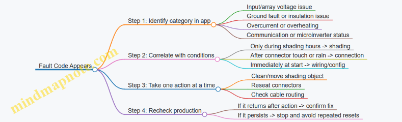
Practical Response Steps
- Record the pattern. Note the time of day, weather, and whether the issue happens after any movement on the balcony.
- Inspect connectors before cleaning. Cleaning is safe, but repeated connector handling can worsen a marginal connection. Start with a careful visual check.
- Reseat connectors once, correctly. If a connector is loose, reseat it fully and ensure the cable isn’t pulling on it.
- Address shading with small changes. Move the object causing the shadow or adjust placement so the shadow no longer covers the panel.
- Verify with the app. Look for improvement in the same time window that previously failed.
When to Stop and Escalate Internally
If a fault code indicates an insulation or ground-related issue, or if you see signs of damaged cable jackets or water inside a connector, stop troubleshooting and avoid repeated power cycling. Those conditions can turn a fixable problem into a safety problem.
Example: Water in a Connector Housing
- Observation: A connector looks fogged or has visible moisture.
- Action: Do not keep reseating it repeatedly. Drying and reseating may not be enough if the connector is compromised.
- Result: Treat it as a connection integrity issue and address it with the system’s support path or a qualified electrician.
The fastest path to stable production is simple: identify whether the problem follows the sun or follows the cables, then make one targeted change and confirm it with the app.
10.5 Documenting Results for Maintenance and Future Moves
A good documentation habit turns “it stopped working” into “here’s what changed.” The goal is simple: capture what you installed, what it produced, what you adjusted, and what you did when something went wrong—so the next maintenance session is faster and less guessy.
What to Record After Installation
Start with a one-page install summary you can find in seconds.
- System identity: panel model(s), inverter or microinverter model(s), battery model (if any), and serial numbers.
- Electrical layout: where the panels mount, where the inverter sits, and the route of major cables (rail-to-inverter, inverter-to-outlet or breaker).
- Settings snapshot: any app settings, battery charge limits, and whether the system exports or stays self-consumption only.
- Weather context: your typical balcony exposure notes (e.g., “morning sun, partial railing shade after 2 pm”).
Example: If your app shows lower production on cloudy weeks, you’ll still know whether the drop matches weather or a mounting shift.
What to Record for Ongoing Maintenance
Maintenance documentation should answer two questions: “Is it still behaving normally?” and “What did I touch last?”
- Monthly production check: note total daily average (or the app’s monthly total) and compare it to your own baseline.
- Visual inspection log: record dates and what you checked—panel cleanliness, cable strain points, connector tightness, and any water pooling near mounts.
- Connector and cable observations: write down any signs of looseness, discoloration, or repeated fault messages.
- Battery health notes: if you have a battery, record charge cycles count and any warnings shown in the app.
Example: If you see a fault code after a storm, your log should include the storm date, wind direction if you noticed it, and whether any connectors were exposed to spray.
A Simple Baseline Method That Doesn’t Require Spreadsheets
You can build a baseline without turning your balcony into an accounting department.
- Pick three clear days in the first two weeks.
- For each day, record peak production and total daily energy from the app.
- Compute a rough range: “typical daily total is about X to Y.”
Example: If your typical daily total is 6–8 kWh during clear days, a sudden repeatable drop to 2–3 kWh likely indicates shading, a loose connector, or a configuration change.
Maintenance Notes That Help Future You
When you perform any action, document it like a checklist, not a story.
- Date and time of the action.
- What you changed (cleaned panels, reseated a connector, adjusted a mount angle, replaced a cable).
- Before-and-after evidence (app production for the next day, whether a fault cleared).
- Any parts used (new connector, replacement cable length, sealant type if applicable).
Example: If you reseat a connector and production returns to baseline within 24 hours, that’s a strong indicator the issue was intermittent contact rather than shading.
Mind Map: Documentation Workflow
Mind Map: Future Move Packet
Example: A Maintenance Entry You Can Trust
2026-03-15 16:32 — Noted app fault “inverter communication intermittent.”
- Before: daily total 3.1 kWh, peak 420 W (baseline clear-day range 6–8 kWh).
- Action: reseated the panel-to-inverter connector at the inverter housing; checked cable for pinch near the rail clamp.
- After: next day total 7.2 kWh; no fault messages.
- Parts used: none.
This entry is useful because it includes evidence, not just the action.
Storage Format That Survives Real Life
Use one folder (digital and optionally printed) with consistent naming: “BalconySolar_InstallDate_SystemName.” Include:
- Photos of the mounting points and connector locations.
- A diagram of the cable route from panels to inverter to outlet/breaker.
- A copy of any app screenshots showing key settings.
Example: If you move apartments and reinstall later, you can recreate the configuration without guessing which toggle you used the first time.
Quick Checklist for the End of Each Maintenance Session
Before you close the folder for the day, confirm you captured:
- What you checked.
- What you changed.
- What the app showed afterward.
- Any parts or seals you used.
That last step keeps your documentation honest, and it makes the next troubleshooting session shorter.
11. Maintenance, Weather Handling, and Seasonal Procedures
11.1 Cleaning Panels Safely Without Damaging Coatings
Balcony solar panels usually have a glass front with an anti-reflective coating and a protective surface layer. Cleaning is mostly about removing dust and pollen without scratching the glass or forcing water into places it shouldn’t go. The safest approach is gentle, controlled, and boring.
What You’re Trying to Remove
Start by identifying the common culprits:
- Dry dust and city grime: wipes off with minimal pressure.
- Pollen: can smear if you dry-wipe it.
- Bird droppings: need extra attention because they can be acidic and harder to remove.
- Hard-water spots: usually require a rinse strategy rather than aggressive scrubbing.
A quick visual check helps you choose the right method. If you can see streaks or sticky spots, plan for a pre-rinse before any contact.
When to Clean
Clean when panels are cool. Midday heat makes water evaporate fast, leaving mineral residue and increasing the chance of streaking. Early morning or late afternoon is ideal. If it rained recently, wait until the surface is mostly dry so you can see what remains.
Tools That Don’t Fight Back
Use tools that are designed for glass and solar surfaces:
- Soft microfiber cloths or a squeegee with a soft rubber edge.
- A soft brush with plastic bristles for loosened debris.
- A hose with a gentle spray or a bucket with clean water.
Avoid:
- Abrasive pads, scouring sponges, or anything labeled “scratch” or “heavy duty.”
- Paper towels or rough rags that can leave micro-scratches.
- Metal scrapers for stuck material.
The Safe Cleaning Process
- Rinse first: Use a gentle spray to remove loose dust. This prevents grit from turning into sandpaper.
- Pre-soak stubborn areas: For pollen or light residue, let water sit briefly so it loosens.
- Wipe lightly or squeegee: If you use cloth, apply minimal pressure and use straight strokes. If you squeegee, keep the rubber edge clean and don’t drag grit.
- Final rinse: Remove any remaining film.
- Let it dry naturally: If you must reduce streaks, use a clean squeegee pass rather than repeated wiping.
A helpful rule: if you feel resistance, stop and rinse again. Pressure is the enemy of coatings.
Cleaning Solutions That Behave
Plain water is often enough. If you need a cleaner, choose one that is mild and intended for glass. Mix according to the label and test on a small corner first. Never use solvents, ammonia-heavy products, or anything that can leave residue.
For bird droppings, use a longer soak with clean water before wiping. If residue persists, repeat the soak rather than scrubbing harder.
Water Management on Balconies
Balcony setups can have tight edges, cable runs, and junction areas. Keep water flow controlled:
- Rinse from the top down so runoff carries dirt away.
- Avoid directing high-pressure water at connectors, junction boxes, or cable entry points.
- Don’t let dirty rinse water pool around mounting hardware.
If your system uses a battery or inverter nearby, keep the cleaning area separate so splashes don’t travel where they shouldn’t.
Step-By-Step Example
Example: dusty south-facing balcony panel after a dry week
- Morning cool-down: wait until the glass is not hot.
- Gentle rinse: hose spray to knock off loose dust.
- Light wipe: microfiber cloth with minimal pressure only where you still see haze.
- Final rinse: remove any film.
- Dry: allow natural drying.
Example: pollen streaks on a partially shaded panel
- Pre-rinse thoroughly to avoid smearing.
- Let water sit for a few minutes.
- Use a squeegee pass with a clean rubber edge.
- Final rinse and natural dry.
Mind Map: Cleaning Safely Without Damaging Coatings
Quick Safety Checklist
- Glass is cool to the touch.
- Tools are clean and soft.
- You rinse before wiping.
- You use minimal pressure.
- You keep water away from connectors and cable entry points.
If you follow those steps, cleaning becomes a routine maintenance task rather than a “will this scratch?” guessing game.
11.2 Inspecting Mounts, Cables, and Connectors After Storms
After a storm, your goal is to confirm three things: the panels stayed where they were meant to be, the wiring stayed protected, and the electrical connections stayed tight and dry. Do this in a repeatable order so you don’t miss the small stuff that causes big headaches.
Step 1: Make It Safe Before You Look
Turn off the system using the normal shutdown method for your setup (inverter/app switch or disconnect, depending on your components). If you can’t confirm a safe state, wait until the balcony is dry and the panels are not producing power. Then inspect from the ground first, using binoculars or a phone camera zoom, to avoid stepping on wet surfaces.
Step 2: Check Mounts for Movement and Stress
Start with the mounting points, not the panel glass. Look for:
- Gaps between brackets and the rail or wall.
- New rust around fasteners (a sign water got into the hardware).
- Bent rails or loosened clamps.
- Cracks in sealant where mounts penetrate waterproof surfaces.
Example: If your system uses a railing clamp, try a gentle push on the panel frame. It should not shift more than a tiny fraction of a millimeter. If it does, tighten the clamp hardware to the manufacturer’s spec and re-check after the balcony dries.
Step 3: Inspect Cable Runs for Physical Damage
Follow the cable path from panel to inverter. Storms often create damage in predictable places:
- Where cables flex at the panel frame.
- Where cables pass through clips or run along sharp edges.
- Where cables meet weatherproof boxes.
Look for cuts, flattening, kinks, or abrasion marks. If you see exposed conductor or damaged outer jacket, stop and replace the affected cable section rather than “patching” it. A cable that looks okay can still have internal micro-damage, so treat any jacket breach as a real problem.
Step 4: Check Connectors for Water Intrusion
Connectors should be dry and fully seated. Inspect:
- Connector locking tabs (they should click or visibly lock).
- Moisture inside the connector body.
- Corrosion on metal contacts.
- Loose strain relief where the cable enters a connector.
Example: After a heavy rain, you might find a connector that looks intact but has a faint fogging inside. That usually means water got past the seal. Disconnect, dry the connector thoroughly, and re-seat it. If corrosion is present, replace the connector set.
Step 5: Verify Cable Management and Drainage
Storms can force water into places it shouldn’t go. Confirm that cables are routed so water doesn’t pool at connector ends. Use clips or ties so the cable makes a smooth path with no sag that can hold water. If you have any low spots, re-route to create a gentle slope away from connectors.
Step 6: Confirm Panel Alignment and Surface Contact
Panels can shift slightly after wind gusts. Check that the panel frame still matches its intended tilt and that mounting points remain evenly loaded. Uneven contact can stress one side of the frame and loosen hardware over time.
Step 7: Quick Electrical Sanity Checks
Without doing anything beyond your comfort level, use the system’s monitoring app to confirm production is normal for the current conditions. If output is zero or erratic after you’ve verified physical integrity, re-check connector seating and any inline fuses or breakers used in your setup.
Mind Map: Post-Storm Inspection Flow
Case Example: Windy Rain on a Renter-Friendly Setup
A renter uses a drilling-free railing mount with quick clamps and a short cable run to a microinverter. After a storm, they find one clamp slightly rotated and a cable clip missing. They tighten the clamp, replace the missing clip, and re-seat the connector. The app shows normal production the next clear day, confirming the issue was mechanical rather than electrical.
Case Example: Heavy Rain and a Connector That “Looks Fine”
A balcony system has a weatherproof junction box near the rail. After rain, the box is dry outside, but the connector inside shows mild discoloration at the contact area. The owner replaces the connector set and re-routes the cable so the connector end is not the lowest point. Production returns to expected levels, and the fix addresses the water path rather than only the symptom.
11.3 Managing Snow, Ice, and Heavy Rain Conditions on Balconies
Balcony solar systems usually fail in predictable ways during winter and storms: water gets into connectors, ice blocks airflow and creates uneven loads, and snow shading lasts long enough to drop output. The goal is simple—keep the system dry where it should be dry, avoid mechanical stress, and restore normal operation safely.
What Changes in Snow and Ice
Snow and ice affect both energy production and physical forces. Snow mainly reduces output by blocking sunlight; ice adds weight and can lift or stress mounts if it freezes unevenly. If your panels are angled, snow often slides off more easily, but balcony railings and limited tilt can reduce that benefit.
A practical rule: treat snow as a shading issue first, and a load issue second. If you can see the panel surface clearly through the snow layer, the system is already producing near zero, so you can focus on safe clearing rather than trying to “wait it out” indefinitely.
Safe Snow Removal Practices
Use methods that minimize scratching and avoid bending the frame.
- Let loose snow fall naturally when possible. If the panel is not buried and the mount is stable, a gentle wait can be enough.
- Use a soft tool for surface clearing. A plastic snow brush or a broom with soft bristles works better than metal scrapers.
- Avoid striking the frame or junction boxes. Impact can loosen cable glands or stress internal wiring.
- Clear from the edges toward the center. This reduces the chance of pulling on the panel surface.
Example: If a 1–2 cm layer covers the panel after a light snowfall, brush lightly from the top edge downward. Stop if you feel resistance from ice; forcing it can damage the coating.
Handling Ice Without Breaking Things
Ice is harder than snow because it bonds. The safest approach is to prevent bonding in the first place and to remove only what you can remove without force.
- Do not chip ice with sharp tools. Scratches become weak points for corrosion.
- Use gentle de-icing only if the system is designed for it. If you’re unsure, rely on natural thaw and safe brushing of loose fragments.
- Watch for ice dams around mounting points. If ice forms at the bottom edge of a panel, it can trap water and increase stress.
Example: After a freeze-thaw cycle, you notice a clear sheet of ice along the lower edge. Instead of scraping, wait for partial thaw, then remove loosened flakes with a soft brush.
Heavy Rain and Wind Considerations
Heavy rain is usually less about water intrusion than about water paths. Water can travel along cables, enter connectors, or pool around mounts if drainage is poor.
- Keep cable runs with drip loops. A drip loop ensures water doesn’t follow the cable into the connector.
- Check connector seals after storms. Look for gaps, misalignment, or moisture inside housings.
- Confirm strain relief is intact. Cables should not tug when wind pushes the panel.
Example: During a storm, you hear a faint tapping from the balcony. After the rain, inspect the cable where it exits the panel frame. If it looks taut or kinked, adjust routing so wind loads don’t transmit into the connector.
Operational Safety During Bad Weather
If your system includes an inverter or battery, treat severe weather as a “do not improvise” moment.
- Avoid disconnecting connectors while wet. Wait until surfaces are dry.
- Do not walk on panels or mounts. Balcony floors are for you; panels are for the sun.
- If you see exposed wiring or damaged insulation, stop using the system. Replace damaged components rather than patching.
Mind Map: Winter and Storm Response
Quick Balcony Checklist After a Storm
- Panels: surface clear of loose snow; no visible cracks or lifted edges.
- Cables: no kinks, no exposed insulation, connectors seated firmly.
- Mounts: no shifting, no new gaps, drainage not blocked.
- Water: no pooling around junction areas.
Example: After a heavy rain, you find water droplets inside a connector housing. Dry the area, then reseat or replace the connector if moisture persists. Don’t keep operating “to see if it dries out,” because water intrusion can worsen with repeated cycles.
Example Scenarios
Scenario 1: Light snow, clear sky. Output is low, but the load is manageable. Brush lightly if the layer is thick enough to cover most of the surface.
Scenario 2: Freeze-thaw with ice sheets. Natural thaw is safer than scraping. Remove only loosened pieces and inspect mounts for stress marks.
Scenario 3: Heavy rain plus gusty wind. Focus on cable strain relief and connector seals. If anything looks pulled or misaligned, correct the routing before the next storm.
Managing winter weather is mostly about restraint: use soft tools, avoid forcing ice, and treat connectors as the system’s “waterproofing weak points.” When you keep water from traveling where it shouldn’t and prevent mechanical stress from building up, the system stays both functional and intact.
11.4 Seasonal Re-Checks for Tightening, Alignment, and Drainage
Balcony solar systems live in a place where water, wind, and temperature swings all get a vote. A seasonal re-check is a short routine that catches small issues before they become annoying or expensive.
What to Re-Check Each Season
Start with a quick visual scan, then move to hands-on checks. Use the same order every time so you don’t skip the important bits.
-
Tightening and fastener condition
- Check mounting clamps, rail brackets, and any through-bolts for snugness. If a fastener has a locking nut or thread locker, verify it hasn’t loosened.
- Look for corrosion at contact points, especially where dissimilar metals meet. A light surface oxidation is common; flaking or pitting is not.
- Example: If your system uses a railing clamp, try gently rocking the panel frame by hand. If you feel movement at the clamp, tighten and re-check after a day.
-
Panel alignment and frame straightness
- Confirm the panel sits flat in its mount. Misalignment can reduce output and can also change how water runs off.
- Check that tilt adjustments (if your mount allows them) are still set to the intended angle.
- Example: After winter, you may find one corner slightly higher. That can happen when ice expands and contracts around the mount. Reset the tilt and re-tighten.
-
Cable routing and strain relief
- Inspect cable clips, ties, and any protective conduits. Look for rubbing, kinks, or spots where the cable can flex repeatedly.
- Ensure connectors are not bearing weight. A connector that’s tugged by the cable is a connector that will eventually complain.
- Example: If you see a cable loop touching the panel frame, adjust the routing so the loop hangs with slack rather than tension.
-
Drainage paths and water management
- Clear debris from around mounts and under any raised brackets. Leaves and grit hold water against metal and can encourage corrosion.
- Verify that water can flow away from the mounting interface. If your mount creates a “cup,” add a small clearance path by repositioning the bracket or removing obstructions.
- Example: If you notice water pooling at the base of a railing mount after rain, check whether the clamp sits over a seam or ledge that traps water. Repositioning the clamp a few centimeters often fixes it.
-
Connector seals and weatherproofing
- Check that cable glands and weather caps are seated correctly. A seal that looks fine can still be slightly twisted.
- Look for moisture inside connector housings. If you see it, stop using the system until the issue is addressed.
Mind Map: Seasonal Re-Checks
A Simple Seasonal Checklist
Use this as a repeatable routine. It’s short enough to do in one sitting.
- Before you start: Ensure the system is safe to handle (unplug or switch off as your setup requires).
- Tightening: Snug all accessible mounting points; do not overtighten to the point of deforming brackets.
- Alignment: Confirm panel angle and that the frame is not twisted.
- Cables: Check routing, clips, and connector seating.
- Drainage: Remove debris around mounts; confirm water flows away.
- Weatherproofing: Inspect seals and housings for damage.
Example: Spring After Heavy Rain
You notice the panel looks slightly tilted compared to last season. During the check, you find grit packed under one bracket, creating a small lift on that side. After clearing the debris, you reset the tilt, tighten the bracket, and re-route the cable so it doesn’t pull on the connector. The next rain shows water moving away instead of pooling.
Example: Autumn Before Cooler Nights
Cooler temperatures can make some materials contract, and wind can work loose fasteners over time. You tighten the clamps, verify the frame is still straight, and check that cable slack is still present. You also confirm that the drainage path around the mount is clear of leaves, which often accumulate before winter.
What “Good” Looks Like After the Check
After tightening, alignment should be consistent across corners. Cables should have gentle slack without sagging into pinch points. Water should not pool at the mounting interface after rain. Connectors should be dry and fully seated. If any of those conditions fail, address the specific cause rather than repeating the same adjustment.
11.5 Safe Shutdown and Reinstallation for Apartment Moves
A balcony solar system is usually easy to move, but the safe part is in the details: power down in the right order, protect connectors from moisture, and reinstall so the mounting stays stable and the wiring stays strain-free.
Shutdown Checklist Before You Touch Anything
- Stop solar input safely: If your system has a DC disconnect or panel-level switch, use it first. If it doesn’t, cover the panels with an opaque tarp long enough to prevent active generation.
- Turn off AC output: Switch off the inverter or microinverter AC breaker (or the dedicated circuit breaker if your setup uses one). This prevents backfeed and reduces the chance of live terminals while you disconnect cables.
- Disconnect in a dry, controlled order: Unplug AC-side connections first only if the manufacturer instructs it that way; otherwise, follow the system’s connector labeling. Keep connectors off the balcony floor and away from puddles.
- Let capacitors discharge: Wait the time stated in your manual before touching internal electronics. If you don’t have the manual, wait at least 10 minutes after power is removed.
- Document before removal: Take photos of cable routing, connector positions, and mounting points. This makes reinstallation faster and reduces “mystery cable” moments.
Packing and Protection for Move Day
- Keep connectors clean and dry: Wipe dust and moisture from connector faces with a dry cloth. If a connector got wet, dry it thoroughly before packing.
- Avoid bending cables at the ends: Coil with gentle radius. Sharp bends near plugs can weaken strain relief.
- Label everything: Use tape labels like “Panel A to Inverter,” “Battery to Inverter,” and “AC Output.” Labels beat memory, especially after a long moving day.
- Store mounting hardware separately: Bag bolts, clamps, and adapters by mounting location. If you reuse the same balcony, you’ll still want the right parts in the right order.
Reinstallation Checklist at the New Apartment
- Confirm the new balcony matches your mounting plan: Check railing type, wall material, and drainage paths. A mount that works on one balcony may not hold on another.
- Inspect all components: Look for cracked panel frames, damaged cable jackets, loose connector seals, and any corrosion on metal parts.
- Reinstall mounts without forcing alignment: If holes don’t line up, don’t “make it fit” by bending rails or stretching clamps. Reposition the mount or use the correct adapter.
- Restore cable routing exactly: Keep cables away from sharp edges, moving parts, and areas where water pools. Use the same clips or ties you used before, but don’t overtighten and crush insulation.
- Check connector seating: Push connectors until they click or fully seat, then verify the weather seal is in place. A partially seated connector is a common cause of low output.
- Verify grounding and bonding: If your system requires grounding, confirm it’s connected exactly as before. Loose grounding can create safety and performance issues.
- Perform a controlled first power-on: Start with the inverter/breaker off, connect everything, then turn on the AC breaker. Finally, remove any panel covers so generation begins.
- Run a short performance check: In the first hour, confirm the monitoring app shows production and no fault codes. If production is zero, stop and re-check connections before leaving the system unattended.
Mind Map: Safe Shutdown and Reinstallation
Example: Renter-Friendly Move with No Drilling
A renter uses clamp mounts on a balcony railing. On move day, they cover the panels with a tarp, switch off the AC breaker, then unplug the panel-to-inverter connectors while standing on a dry surface. They label each cable run, coil the cables loosely, and pack the clamps in a labeled bag.
At the new apartment, they compare the railing profile to the old one. If the new railing has a different thickness, they swap to the correct clamp adapter rather than tightening harder. They reinstall the cable clips so the cable path stays the same height and avoids the drain line. After power-on, they check the app for production within the first hour and confirm no fault codes appear.
Example: Move with Battery Storage
A system includes a battery module with an AC output and a separate battery connection. During shutdown, the owner turns off the AC breaker first, then disconnects the battery cables only after the discharge wait time. They pack the battery upright, keep terminals protected with the provided caps, and store it indoors.
At the new apartment, they reinstall the battery where ventilation matches the original setup and confirm the battery-to-inverter connector is fully seated. They start the inverter, then check that the battery status reads normally before allowing solar charging. If the battery shows an error, they stop and re-check connector seating and cable routing rather than continuing to power-cycle.
Quick Safety Rules That Prevent Most Problems
- Power down before disconnecting: Live disconnects are the fastest way to create connector damage.
- Keep connectors dry: Moisture plus imperfect seating equals low output and intermittent faults.
- Don’t force mounts: If alignment doesn’t work, the mount needs adjustment or different hardware.
- Restore strain relief: Cables should be supported so weight never hangs on plugs.
- Verify after power-on: A brief monitoring check catches issues early while you’re still on-site.
12. Installation Playbooks with Real Apartment Scenarios
12.1 Case Study: Small South-Facing Balcony with Limited Wall Space
This balcony is about 1.2 m deep and 2.5 m wide. It faces south, but the railing is tall and the only usable wall area is a narrow strip beside the door. The goal is simple: run a few daily loads (fridge, Wi‑Fi, lights) and reduce grid usage without drilling into the building structure.
Starting Assumptions
- Balcony receives strong sun most days, but the door frame and railing create partial shading near the edges.
- The apartment has a standard outlet near the door, but no dedicated solar circuit.
- The user wants plug-and-play behavior: quick setup, clear monitoring, and safe shutdown.
Mind Map: Planning Constraints and Decisions
Step 1: Measure Usable Panel Area
You can’t size a system from balcony dimensions alone; you size it from where the panels can actually sit. Measure three things:
- Panel footprint: the maximum panel width and height that fit without blocking the door swing.
- Clearance: leave a small gap behind the panel so cables and connectors don’t get pinched.
- Edge shading: stand where the panel corners would be and note where the railing casts shade.
Example: If you can fit two panels side-by-side but the left panel edge is shaded for 45 minutes each morning, you still can use both panels—just don’t expect identical output.
Step 2: Estimate Daily Energy with a Simple Method
Use a conservative “sun hours” estimate based on your observations rather than a perfect theoretical number. For a south-facing balcony in a typical urban setting, a practical planning range might be 3–5 peak sun hours depending on season.
Example calculation:
- Two 400 W panels = 800 W nameplate.
- Assume 4 peak sun hours on an average day.
- Estimated daily energy: 800 W × 4 h = 3,200 Wh (3.2 kWh).
- Apply a realism factor for balcony losses (dust, wiring, partial shading): say 0.75.
- Planning target: 3.2 kWh × 0.75 ≈ 2.4 kWh/day.
This number is not a promise; it’s a sizing anchor that keeps expectations aligned with reality.
Step 3: Choose a Plug-and-Play Electrical Layout
With limited wall space, you want electronics that tolerate uneven shading without forcing the whole system to underperform. Panel-level power electronics help because one shaded panel doesn’t drag down the other as much.
Example approach:
- Use two panels with panel-level power electronics (often microinverters).
- Route cables along the balcony rail line using clips rated for outdoor use.
- Terminate at a system interface that is designed for plug-in use.
Key best practice: keep cable runs straight and protected. If a cable crosses where you step, add a physical cover or reroute; “it’s fine” is how connectors get stressed.
Step 4: Match System Output to Everyday Loads
A small balcony system rarely powers everything. Instead, it should cover the loads that run consistently.
Example load plan:
- Fridge: runs continuously.
- Wi‑Fi router: always on.
- LED lights: used in the evening.
If your plug-in interface supports monitoring, check whether the system is exporting to the apartment or simply offsetting loads. The goal is to reduce grid draw during the sun window, not to chase a specific percentage.
Step 5: Install with Limited Wall Space in Mind
Because the wall strip is narrow, prioritize a railing mount that keeps the panel plane stable and allows airflow behind the panels.
Example mounting checklist:
- Clamp mounts are tightened to the manufacturer’s torque guidance.
- Panel tilt is set to balance sun capture and wind resistance.
- Cable entry points are sealed with weather-rated connectors.
- Leave service slack so you can remove a panel without dismantling the whole run.
Step 6: Verify Performance and Diagnose Shading
After installation, compare production on clear days to your planning target.
Example verification routine:
- Pick a day with similar weather to your estimate.
- Note daily production in the monitoring app.
- If output is consistently low, check for one of these:
- A connector not fully seated.
- A panel angled too flat for the balcony’s constraints.
- Edge shading that’s worse than you thought.
Mind the nuance: partial shading often affects the shaded panel more than the unshaded one. With panel-level electronics, the system should still perform reasonably overall.
Mind Map: What “Good” Looks Like
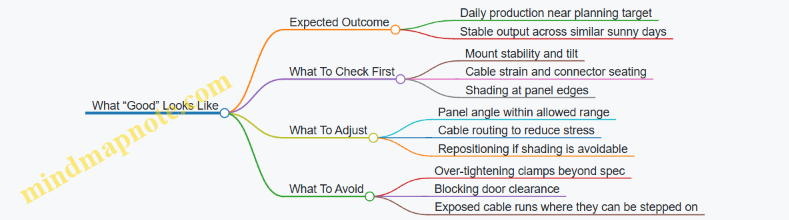
Quick Example Layout Summary
- Two panels mounted on a drilling-free railing clamp system.
- Panel-level power electronics to reduce the impact of edge shading.
- Cable routed along the rail with weather-rated clips.
- Monitoring used to confirm daily energy matches the conservative estimate.
This setup works because it respects the balcony’s physical limits while keeping the electrical behavior predictable when the railing and door frame create uneven light.
12.2 Case Study: North-Facing Balcony With High Shading From Nearby Buildings
A renter in a mid-rise apartment has a north-facing balcony. The balcony is partially blocked by a neighboring building that casts shade from late morning through early evening. They want a plug-and-play balcony solar setup that can be installed without drilling into the building structure.
The Starting Constraints
The balcony is 1.6 m wide and 3.0 m deep, with a metal railing and a narrow wall section on the inside corner. The tenant can place panels on the railing using a clamp system, but they cannot run cables through the building envelope. The electrical goal is to offset daytime loads: a fridge, Wi‑Fi router, and occasional laptop charging.
A key reality check: north-facing solar in many locations produces less energy than south-facing, and heavy shading can reduce output sharply. The plan therefore focuses on maximizing usable hours and avoiding “false confidence” from a sunny-day test.
Site Assessment That Matches the Real Problem
Instead of measuring only peak sunlight, they map shade timing. They do three short observation sessions on clear days, each lasting 30 minutes, and record whether the panel area is fully lit, partially lit, or fully shaded.
They also note that shading is not uniform. The neighboring building creates a moving edge of shadow, so one side of the balcony may be lit while the other side is shaded. This matters because string-level systems can be dragged down by the most shaded portion.
System Choice That Handles Partial Shading
They choose a plug-and-play system with module-level power electronics (microinverters or power optimizers). The reasoning is simple: when one panel is shaded, the rest can still operate closer to their own conditions. With a single inverter and no per-module electronics, a shaded panel can reduce the output of the entire string.
They also keep the panel count modest. Oversizing panels on a heavily shaded balcony often leads to wasted capacity, because the limiting factor is not panel rating—it’s the hours when the panels receive usable light.
Layout Decision with Clear Tradeoffs
They mount panels on the railing using clamp brackets rated for outdoor use. The panel face is set to the maximum tilt allowed by the railing geometry, because tilt can improve morning or late-day capture when the sun angle is low.
They avoid placing panels too close to the shade edge. A small shift of the array toward the least-shaded side can increase the number of “partially lit” hours, which is more valuable than chasing a brief peak.
Example Energy Planning with Realistic Assumptions
They list daily loads and convert them to watt-hours:
- Fridge: 1.0 kWh/day (typical range, measured later)
- Wi‑Fi router: 8 W average → 0.19 kWh/day
- Laptop charging: 60 W average for 2 hours → 0.12 kWh/day
Total target: about 1.31 kWh/day.
Because shading reduces production, they size the solar array to cover a portion of daytime energy rather than the full daily total. They aim for roughly 0.6–0.9 kWh/day during the months when shade is most severe.
They then set expectations for performance verification: if the system produces 0.3 kWh/day on average during the shaded season, the issue is not “bad luck,” it’s the site. The next step is to adjust layout or reduce reliance on solar for non-essential loads.
Mind Map: North-Facing Shading Case Study
Commissioning and Verification Steps
During first power-on, they confirm each panel’s production in the app. If one panel consistently shows much lower output than neighbors, they check for connector seating and verify that the panel face is not blocked by a bracket or cable.
They also perform a simple “shade test.” On a day when the shadow edge passes across the balcony, they watch whether the app shows independent panel behavior. With module-level electronics, shaded panels drop while others remain closer to their own output.
Practical Example Adjustments After the First Week
After seven days, they notice that the array produces most energy in two windows: late morning and late afternoon. Midday is mostly shaded. They respond by changing usage timing rather than changing hardware.
They schedule the laptop charging and any high-draw tasks to the brighter windows. They keep the fridge on its normal cycle, because it’s not practical to shift, but they treat it as the baseline load that solar can offset when available.
If production is lower than expected even during the brighter windows, they revisit the physical placement. A small repositioning—moving the array a few centimeters to reduce the overlap with the shadow edge—can improve the fraction of “partially lit” hours.
What This Case Teaches
This balcony doesn’t fail because the tenant chose solar. It succeeds when the design matches the limiting factor: shading. The most important decisions are using per-module electronics, sizing for partial offset, and verifying panel-by-panel behavior with real shade timing.
12.3 Case Study: Renter-Friendly Drilling-Free Setup with Portable Mounting
Maya rents a second-floor apartment with a balcony that has a metal railing and a narrow floor. She wants to run a small fridge, charge phones, and power a few lights during evening hours. She also needs a setup that can be removed without leaving holes in the building.
The Constraints
Maya’s balcony has three practical limits: (1) the railing can’t be modified permanently, (2) the balcony floor must stay walkable, and (3) the system must handle typical rain and morning dew. She also has a landlord who requires that any installation be reversible and that cables be secured so they can’t snag someone’s foot.
The Chosen Approach
She uses a portable mounting method that clamps to the railing rather than drilling into it. The panels are mounted on a frame that can be carried as a unit. The electrical side uses plug-and-play connectors and a single weatherproof cable run that stays inside a protective route.
A key decision is keeping the system “appliance-first.” Instead of trying to power everything, she targets a small daily energy budget. That prevents the common renter problem: buying more hardware than the balcony can reliably produce.
Step-By-Step Installation Flow
- Measure the usable sun window. She checks when the balcony receives direct light and notes the start and end times. She uses that window to estimate daily energy, not peak output.
- Plan the layout before mounting. She places the frame on the balcony floor temporarily to confirm it won’t block the door swing or create a trip hazard.
- Mount the frame with clamps. She tightens clamp points evenly and verifies the frame doesn’t rock when she pushes it by hand. If it moves, she repositions the clamp locations rather than over-tightening.
- Route cables along a protected path. She uses cable clips rated for outdoor use and keeps the cable away from sharp edges. Where the cable crosses the railing, she adds strain relief so connector weight isn’t hanging.
- Connect panels to the power unit. She follows the connector sequence exactly and checks that each connection clicks fully. She avoids forcing connectors, because bent pins are the fastest way to turn “plug-and-play” into “plug-and-cry.”
- Secure slack and create a safe removal path. She leaves a small service loop near the power unit so she can disconnect without pulling on the panel cables.
- Run a first test at low load. She powers a small device first, confirms the app readings look reasonable, and only then connects the fridge.
Example Energy Plan
Maya lists her target loads: a fridge (running intermittently), phone charging, and two LED lights. She estimates daily watt-hours by using the device’s typical consumption and the hours she expects to run them. She then chooses a panel size that matches that daily number for her sun window. The result is a system that produces useful energy without constantly chasing “maximum” output.
Mind Map: Renter-Friendly Portable Setup
Example: A Simple “No-Regrets” Checklist
- Clamps: frame doesn’t wobble when pushed gently from multiple angles.
- Cables: no cable is under tension; connectors are not hanging weight.
- Weather: all outdoor connections are fully seated and protected.
- Access: you can reach the power unit and disconnect without moving the panels.
- Walkway: the balcony path remains clear even with the cable route.
What Worked for Maya
After setup, her production readings tracked her sun window rather than surprising her with unrealistic expectations. The portable frame stayed stable in light wind because she positioned it to reduce leverage on the clamps. Her cable route stayed snag-free because she secured slack and avoided crossing the main walking line.
When she needed to clean the balcony, she could remove the frame without touching the building structure. That reversibility mattered more than squeezing out a little extra output, because it kept the installation consistent with her rental agreement and daily routine.
12.4 Case Study: Balcony Solar With Battery Backup for Essential Loads
This case study follows an apartment renter who wants power for a few essentials during outages: Wi‑Fi, a fridge, and phone charging. The balcony has partial sun, and the renter needs a setup that is safe, reversible, and easy to monitor.
Starting Point and Goals
Essential loads list
- Wi‑Fi router and modem: 18–25 W average
- Fridge: 60–120 W cycling, about 1.0–1.5 kWh/day typical
- Phone/laptop charging: 20–60 W for short periods
Goal: Run essentials for 6–10 hours during an outage, without exceeding the balcony system’s limits.
Balcony constraints
- Rail mount preferred (no drilling)
- Some shading from a nearby building during late morning
- Limited space for panels and cable runs
Mind Map: System Design Logic
Step 1: Estimate Outage Energy
Assume a 8-hour outage window.
- Wi‑Fi: 22 W × 8 h = 176 Wh
- Charging: 40 W average × 8 h = 320 Wh
- Fridge: estimate 100 W average during the window (cycling) × 8 h = 800 Wh
Total ≈ 1,296 Wh. Add a practical buffer for inverter losses and fridge variability: 1,600 Wh.
If the battery system provides 80% usable capacity, required nominal capacity is about 2,000 Wh (2 kWh). A 2.4–3.0 kWh battery is a comfortable range for real-world fridge behavior.
Step 2: Size the Solar for Recharge
The goal is not to fully recharge in one sunny afternoon; it’s to keep essentials running and reduce how often you drain the battery.
Assume the balcony gets about 3.5 peak sun hours on average and the system is partially shaded, so real output might be 70–80% of nameplate.
If you install 600 W of panels, expected daily energy is:
- 600 W × 3.5 h × 0.75 ≈ 1,575 Wh/day
That roughly matches the outage energy buffer, meaning the battery can recover over a day when sun is available.
Step 3: Choose Components That Fit the Apartment
Battery and inverter
- Use a battery system designed for backup output with an inverter that can handle fridge startup surges.
- Confirm the inverter’s continuous output is comfortably above the fridge’s typical draw.
Plug-and-play integration
- Prefer a system that includes pre-matched connectors and a backup output circuit.
- If the system offers an “essential loads” outlet or sub-circuit, use it to avoid accidental overload.
Mounting
- Use a railing mount rated for wind load and compatible with the panel frame.
- Add strain relief so cable weight never hangs on connectors.
Example: A Practical Essential Loads Setup
The renter uses a small power strip labeled “Backup Only” plugged into the system’s essential output.
- Router and modem: always on
- Fridge: plugged directly into the essential output
- Charging: plugged in when needed
This keeps the battery from powering non-essential devices like kettles or space heaters, which would drain capacity quickly.
Mind Map: Installation and Verification
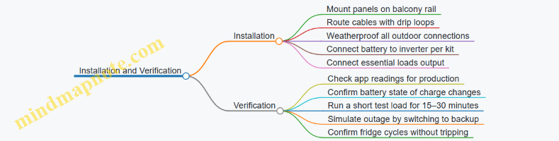
Step 4: Commissioning and First Test
- Daytime check: Ensure the app shows panel production and battery charging.
- Load test: With sun available, run Wi‑Fi and charging for 30 minutes and confirm stable output.
- Backup test: Switch to backup mode and observe:
- Router stays online
- Fridge starts and continues cycling
- No fault codes appear
If the inverter trips during fridge startup, reduce other loads and verify the inverter’s surge capability matches the fridge’s compressor behavior.
Step 5: Operating Rules That Prevent Surprises
- Keep the essential outlet limited to the listed devices.
- Avoid running high-watt appliances during backup tests.
- After storms, visually inspect cable routing and connector seals before relying on backup.
What Success Looks Like
On a typical sunny day, the battery should recharge from solar while essentials run. During an outage, the system should maintain Wi‑Fi and keep the fridge cycling without inverter faults, with remaining capacity tracked so you know when to stop charging heavy devices.
12.5 Case Study: Multi-Panel Layout with Cable Management and Monitoring
This scenario uses a renter-friendly, balcony-rail mounting approach with four plug-and-play panels feeding a single inverter system. The goal is steady daily production despite partial shading from a nearby wall, while keeping cables tidy enough that you can still use the balcony without stepping over them.
Apartment Setup and Constraints
The balcony is 2.4 m wide. The railing runs along the long edge, but the left third is shaded for about two hours in the late morning. The user wants to run a small set of loads: a fridge, Wi-Fi router, a few LED lights, and a laptop charger. During the day, the main consumption is intermittent, so the system should prioritize self-use rather than exporting.
A multi-panel layout helps because you can spread panels across the available railing length. Instead of one large panel that gets fully shaded, you place panels so that at least some receive sun during each part of the day.
Panel Layout Plan
Use four panels arranged as two rows of two, but keep them at the same tilt to avoid uneven electrical behavior. Place the shaded-side panels slightly lower in the visual stack so they don’t block the unshaded panels. Keep a small gap between panel frames so rain can drain and so you can access connectors.
A practical rule: if you can’t reach the connector with one hand while standing normally, you’ll hate maintenance later. Leave connector access at the “front edge” of the balcony where you can reach without leaning over the railing.
Cable Routing Strategy
Cable management is not just aesthetics; it prevents performance problems. Loose cables can work their way into contact with wet surfaces, and repeated flexing at the same point can damage insulation.
Route DC cables from each panel to a central junction point near the inverter. Use UV-resistant cable ties and keep bends gentle. Avoid sharp corners around railing posts, and never let cables hang in a way that forms a loop where water collects.
Create three cable zones:
- Panel-to-rail runs: short, straight paths with slack only where you need it for connector mating.
- Rail-to-central run: one continuous path down to the inverter location.
- Inverter-to-outlet or circuit run: keep this separate from DC wiring so you can troubleshoot without guessing.
If the system includes a monitoring module, place it near the inverter and keep its cable away from high-current runs.
Monitoring Configuration
Monitoring should answer two questions: “Is the system producing?” and “Is any panel underperforming?”
Set up monitoring so you can see per-panel or per-string production if the system supports it. If it only shows total output, you can still use the app to compare daily totals against your baseline days. For this case, the user records production for the first week and notes the shaded window.
A simple verification routine:
- On a clear day, check that total production rises after sunrise and drops during the shaded period.
- Confirm that the drop is smooth rather than sudden. Sudden drops often indicate a connector issue or a loose plug.
Mind Map: Multi-Panel Layout with Cable Management and Monitoring
Example: Connector Access and Slack Planning
Suppose each panel uses a quick-connect cable. You want enough slack to unplug the connector without pulling on the cable jacket. Measure the distance from the connector to your standing reach point, then add 10–15 cm of extra slack. If you add more, the cable will sag and collect water; if you add less, you’ll tug and stress the connector.
Label each panel cable with a small tag that matches the app’s panel numbering. When you later see Panel 3 producing less, you can physically find Panel 3 without guessing.
Example: Interpreting Shading with Monitoring
On a day when the left third is shaded from 10:30 to 12:30, total production should show a dip during that window. If the dip is only partial, it suggests that at least one panel on the shaded side still receives light. If production drops to near-zero for the entire system during the shaded window, check whether one panel’s connectors are loose or whether a string is being fully blocked.
Example: Cable Inspection After a Rainy Week
After several rain events, inspect the central junction area. Look for:
- Water pooling near connectors
- Cable ties that loosen and allow rubbing
- DC cable sections that touch the railing post directly
Fixing these issues is usually straightforward: reroute to eliminate contact points, add a small drip loop where the cable transitions to a vertical run, and tighten or replace cable ties so the cable doesn’t move when you brush past it.
Summary of Best Practices Used in This Case
This layout works because it spreads shading impact across panels, keeps connector access reachable, routes cables to avoid water traps, and uses monitoring to confirm that production changes match the balcony’s real sun pattern.