Hydrogen Energy Systems Engineering And Industrial Deployment
1. Introduction to Hydrogen Energy Systems
1.1 Overview of Hydrogen as a Clean Energy Carrier
Hydrogen is increasingly recognized as a pivotal clean energy carrier that can play a transformative role in the global transition towards sustainable energy systems. Unlike traditional fossil fuels, hydrogen produces zero carbon emissions at the point of use, making it an attractive option for decarbonizing sectors that are hard to electrify.
What is Hydrogen as an Energy Carrier?
Hydrogen is not a primary energy source but an energy carrier, similar to electricity. It can store, transport, and deliver energy produced from various sources, including renewables.
Key Attributes of Hydrogen as a Clean Energy Carrier
- High Energy Density: Hydrogen has a high gravimetric energy density (~120 MJ/kg), which makes it efficient for energy storage and transport.
- Zero Emissions at Use: When used in fuel cells or combusted, hydrogen emits only water vapor.
- Versatility: Can be used across multiple sectors such as transportation, industry, power generation, and heating.
- Storage Capability: Enables long-term energy storage, addressing intermittency issues of renewables.
Mind Map: Hydrogen as a Clean Energy Carrier
Examples Illustrating Hydrogen’s Role
Example 1: Hydrogen Fuel Cell Vehicles (Transportation)
Hydrogen fuel cell vehicles (FCVs) use hydrogen to generate electricity on-board, emitting only water vapor. Toyota Mirai and Hyundai Nexo are commercial examples demonstrating hydrogen’s potential to decarbonize transport, especially for long-range and heavy-duty applications.
Example 2: Industrial Use in Steel Manufacturing
The HYBRIT project in Sweden uses hydrogen to replace coke in steel production, significantly reducing CO2 emissions. This showcases hydrogen’s potential to decarbonize energy-intensive industries.
Example 3: Renewable Energy Storage
In Germany, large-scale electrolyzers convert excess wind and solar power into hydrogen, which can be stored and later used to generate electricity or heat, helping balance the grid.
Summary
Hydrogen as a clean energy carrier offers a flexible, zero-emission solution to multiple energy challenges. Its ability to integrate with renewable energy sources and serve diverse applications makes it a cornerstone of future clean energy systems. However, realizing its full potential requires overcoming challenges related to cost, infrastructure, and storage.
This foundational understanding sets the stage for deeper exploration into hydrogen production, storage, and deployment strategies in subsequent sections.
1.2 Historical Development and Current Industry Landscape
Hydrogen energy has a rich history that spans over two centuries, evolving from a scientific curiosity to a key player in the global clean energy transition. Understanding this historical context alongside the current industry landscape is essential for energy engineers and project managers to appreciate the trajectory and potential of hydrogen systems.
Early Discoveries and Milestones
- 1766: Henry Cavendish first identified hydrogen as a distinct element, calling it “inflammable air.”
- 1800s: Sir William Grove developed the first fuel cell, laying the groundwork for hydrogen-to-electricity conversion.
- 1930s-1950s: Hydrogen was primarily used in industrial processes such as ammonia synthesis and petroleum refining.
Mind Map: Early Hydrogen Development
Hydrogen in the Space Age
The 1960s marked a significant leap with NASA’s Apollo missions using liquid hydrogen as rocket fuel, demonstrating large-scale hydrogen storage and handling technologies.
- Example: The Space Shuttle program utilized liquid hydrogen and oxygen, showcasing hydrogen’s high energy density and performance.
Mind Map: Hydrogen in Aerospace
The Oil Crisis and Renewed Interest (1970s-1980s)
The oil crises of the 1970s spurred interest in alternative fuels, including hydrogen. Research focused on hydrogen production via electrolysis and fuel cell development for transportation.
- Example: The U.S. Department of Energy initiated programs to explore hydrogen as a transportation fuel.
Modern Era: Hydrogen as a Clean Energy Solution
In the 21st century, hydrogen has emerged as a cornerstone of decarbonization strategies globally.
- Green Hydrogen: Produced via renewable-powered electrolysis, gaining momentum due to zero carbon emissions.
- Blue Hydrogen: Produced from natural gas with carbon capture and storage (CCS).
Mind Map: Modern Hydrogen Landscape
Current Industry Landscape
Global Market Growth
- The hydrogen market is projected to grow at a CAGR of over 8% through 2030.
- Major investments are being made in electrolyzer manufacturing, hydrogen infrastructure, and fuel cell technologies.
Leading Regions and Initiatives
- Europe: The European Hydrogen Backbone initiative aims to create a dedicated hydrogen pipeline network.
- Asia: Japan and South Korea lead in fuel cell deployment and hydrogen refueling infrastructure.
- North America: The U.S. is investing heavily in green hydrogen projects and hydrogen hubs.
Industrial Applications
- Steel production (e.g., HYBRIT project in Sweden) replacing coal with hydrogen.
- Ammonia production using green hydrogen for fertilizer.
- Heavy-duty transportation and maritime sectors adopting hydrogen fuel cells.
Best Practice Example: Japan’s Hydrogen Society Vision
Japan has developed a comprehensive hydrogen strategy focusing on:
- Large-scale hydrogen imports
- Fuel cell vehicles and residential fuel cells
- Integration of hydrogen in power generation
This holistic approach serves as a blueprint for industrial deployment and policy support.
Mind Map: Current Industry Landscape
Summary
The historical evolution of hydrogen energy from early scientific discovery to a pivotal clean energy resource highlights its transformative potential. The current industry landscape is characterized by rapid technological advancements, expanding infrastructure, and strategic policy frameworks that collectively drive the industrial deployment of hydrogen energy systems.
Energy engineers and project managers can leverage this understanding to align their projects with global trends, adopt best practices, and contribute effectively to the hydrogen economy.
1.3 Key Benefits and Challenges of Hydrogen Energy
Hydrogen energy is increasingly recognized as a pivotal element in the transition to a sustainable and low-carbon energy future. Understanding its key benefits and challenges is essential for energy engineers, project managers, and clean energy developers to make informed decisions and design effective systems.
Key Benefits of Hydrogen Energy
-
Zero Carbon Emissions at Point of Use: When hydrogen is used in fuel cells or combusted, the only byproduct is water vapor, making it an exceptionally clean energy carrier.
-
High Energy Density: Hydrogen has a high gravimetric energy density (~120 MJ/kg), which makes it an efficient fuel for transportation and industrial applications.
-
Versatility: Hydrogen can be produced from various sources (renewables, natural gas, biomass) and used across multiple sectors including power generation, transportation, and industrial processes.
-
Energy Storage and Grid Balancing: Hydrogen can store excess renewable energy, helping to balance supply and demand in power grids.
-
Decarbonization of Hard-to-Abate Sectors: Hydrogen offers solutions for sectors like steelmaking, chemicals, and heavy transport where electrification is challenging.
-
Economic Growth and Job Creation: Developing hydrogen infrastructure and technology can stimulate new industries and employment opportunities.
Mind Map: Benefits of Hydrogen Energy
Example: Japan’s Hydrogen Society Vision
Japan is investing heavily in hydrogen to reduce carbon emissions and enhance energy security. Their strategy includes fuel cell vehicles, hydrogen refueling stations, and hydrogen-powered homes, demonstrating hydrogen’s versatility and environmental benefits.
Challenges of Hydrogen Energy
-
Production Cost and Energy Intensity: Green hydrogen production via electrolysis is currently expensive and energy-intensive compared to fossil fuels.
-
Storage and Transportation Difficulties: Hydrogen’s low volumetric energy density requires high-pressure tanks, liquefaction, or chemical carriers, which add complexity and cost.
-
Infrastructure Development: Lack of widespread hydrogen refueling stations and pipelines limits adoption, especially in transportation.
-
Safety Concerns: Hydrogen is highly flammable and leaks are difficult to detect due to its colorless and odorless nature, necessitating stringent safety protocols.
-
Material Compatibility and Durability: Hydrogen can cause embrittlement in metals and degradation in some materials, impacting system longevity.
-
Regulatory and Market Barriers: Unclear regulations, lack of standards, and market uncertainty can slow down deployment.
Mind Map: Challenges of Hydrogen Energy
Example: California Hydrogen Infrastructure Challenges
California’s ambitious hydrogen refueling network faces challenges including high station costs, limited geographic coverage, and ensuring safety standards, illustrating the complexities of infrastructure deployment.
Integrated Best Practice: Balancing Benefits and Challenges
To maximize hydrogen’s potential, projects should adopt a holistic approach:
-
Leverage Renewable Energy for Production: Use surplus solar or wind power to produce green hydrogen, reducing carbon footprint and improving economics.
-
Innovate in Storage Solutions: Explore advanced materials like metal hydrides or liquid organic hydrogen carriers (LOHCs) to improve storage safety and efficiency.
-
Implement Robust Safety Protocols: Employ continuous monitoring, leak detection sensors, and rigorous training to mitigate risks.
-
Engage Stakeholders and Policymakers: Collaborate to develop clear regulations and incentives that support infrastructure growth.
Example: European Hydrogen Valleys
Projects like the Hydrogen Valleys in Europe integrate production, storage, distribution, and end-use applications in a localized ecosystem, addressing challenges through coordinated efforts and demonstrating the benefits of hydrogen energy.
Understanding these benefits and challenges equips energy professionals to design, manage, and deploy hydrogen energy systems effectively, accelerating the clean energy transition.
1.4 Best Practice: Assessing Hydrogen’s Role in Energy Portfolios with Case Study on Japan’s Hydrogen Strategy
Hydrogen is increasingly recognized as a pivotal element in the transition to a low-carbon energy future. Assessing its role within national and corporate energy portfolios requires a structured approach that balances technical feasibility, economic viability, environmental impact, and policy alignment.
Key Steps in Assessing Hydrogen’s Role in Energy Portfolios
Mind Map: Assessing Hydrogen’s Role in Energy Portfolios
Example: Japan’s National Hydrogen Strategy
Japan has been a global pioneer in integrating hydrogen into its energy portfolio, driven by its limited domestic fossil fuel resources and commitment to carbon neutrality by 2050. The Japanese government’s strategy provides a practical example of how to assess and implement hydrogen at scale.
Technical Feasibility
- Focus on fuel cell vehicles (FCVs) and residential fuel cells (ENE-FARM) to create early market demand.
- Investment in large-scale hydrogen production via both fossil-based (with CCS) and renewable electrolysis.
Economic Viability
- Subsidies and incentives to reduce FCV costs and hydrogen refueling infrastructure.
- Public-private partnerships to share investment risks.
Environmental Impact
- Targeting a carbon-neutral hydrogen supply chain by 2030.
- Lifecycle assessments to ensure net emissions reductions.
Policy & Regulatory Framework
- Establishment of safety codes and standards for hydrogen use.
- International cooperation, e.g., with Australia for hydrogen imports.
Stakeholder Engagement
- Collaboration among government, automotive manufacturers, utilities, and research institutions.
Mind Map: Japan’s Hydrogen Strategy Components
Practical Example: ENE-FARM Residential Fuel Cells
- Japan’s ENE-FARM program deploys home fuel cells that generate electricity and heat from hydrogen.
- This decentralized approach reduces grid load and promotes hydrogen use in everyday life.
- Example: A Tokyo suburb where 500 homes adopted ENE-FARM units, resulting in a 30% reduction in household CO2 emissions.
Lessons Learned from Japan’s Approach
- Holistic Integration: Hydrogen must be integrated across production, infrastructure, and end-use sectors.
- Government Leadership: Strong policy frameworks and incentives accelerate market adoption.
- International Collaboration: Importing hydrogen and technology exchange are vital for scaling.
- Public Awareness & Safety: Educating stakeholders and establishing safety standards build trust.
Summary
Assessing hydrogen’s role in energy portfolios requires a multi-dimensional analysis supported by real-world examples. Japan’s strategy exemplifies best practices by combining technical innovation, economic incentives, environmental stewardship, and policy support. Energy engineers and project managers can leverage these insights to design robust hydrogen integration plans tailored to their regional contexts.
2. Fundamentals of Hydrogen Production Technologies
2.1 Electrolysis: Principles and System Design
Electrolysis is a fundamental process in hydrogen energy systems, enabling the production of hydrogen gas by splitting water molecules (H₂O) into hydrogen (H₂) and oxygen (O₂) using electrical energy. This section covers the core principles of electrolysis, the types of electrolyzers, system design considerations, and practical examples to illustrate best practices.
Principles of Electrolysis
Electrolysis involves an electrochemical reaction where an electric current passes through water, causing the following reaction:
\[ 2H_2O (l) \rightarrow 2H_2 (g) + O_2 (g) \]
- Anode (oxidation): Water molecules lose electrons to form oxygen gas and protons.
- Cathode (reduction): Protons gain electrons to form hydrogen gas.
The energy input must overcome the thermodynamic potential (~1.23 V) plus overpotentials due to kinetic and resistive losses.
Types of Electrolyzers
Electrolyzers are classified based on the electrolyte and operating conditions:
- Alkaline Electrolyzers (AEL): Use liquid alkaline solution (KOH or NaOH). Mature technology, lower cost, but lower current density.
- Proton Exchange Membrane (PEM) Electrolyzers: Use a solid polymer electrolyte. High purity hydrogen, fast response, compact design.
- Solid Oxide Electrolyzers (SOEC): Operate at high temperatures (~700-900°C), high efficiency, can use waste heat.
Mind Map: Electrolysis Overview
System Design Considerations
-
Power Supply and Electrical Integration:
- Stable DC power source, often from renewable energy (solar, wind).
- Power electronics to manage load and efficiency.
-
Water Quality and Purification:
- High purity water is essential to prevent electrode degradation.
- Systems include filtration, deionization, and sometimes reverse osmosis.
-
Gas Separation and Handling:
- Efficient separation of hydrogen and oxygen gases to avoid mixing.
- Use of membranes and gas-tight compartments.
-
Thermal Management:
- Electrolysis generates heat; cooling systems maintain optimal temperature.
-
Safety Systems:
- Sensors for hydrogen leaks.
- Pressure relief valves and ventilation.
Mind Map: Electrolyzer System Design
Example: Optimizing Electrolyzer Efficiency in a European Green Hydrogen Plant
A green hydrogen facility in Germany integrates a PEM electrolyzer with a 10 MW solar farm. Key best practices implemented include:
- Dynamic Load Management: The electrolyzer adjusts operation based on solar power availability, maximizing hydrogen production during peak sunlight.
- Water Recycling: The plant uses a closed-loop water purification system to reduce water consumption by 30%.
- Thermal Integration: Waste heat from the electrolyzer is used to preheat incoming water, improving overall system efficiency.
- Safety Protocols: Continuous hydrogen sensors and automated shutdown systems ensure safe operation.
This example demonstrates how system design tailored to renewable inputs and resource optimization can enhance performance and sustainability.
Summary
Electrolysis is a versatile and scalable technology critical for clean hydrogen production. Understanding the principles, selecting appropriate electrolyzer types, and designing integrated systems with attention to power, water, gas, thermal, and safety aspects are essential for successful deployment. Incorporating best practices from operational plants ensures reliability, efficiency, and safety in industrial hydrogen projects.
2.2 Steam Methane Reforming with Carbon Capture
Steam Methane Reforming (SMR) is currently the most widely used industrial process for hydrogen production. It involves reacting methane (CH4) with steam (H2O) at high temperatures (700–1,000°C) in the presence of a catalyst to produce hydrogen (H2), carbon monoxide (CO), and a small amount of carbon dioxide (CO2). The process is typically followed by a water-gas shift reaction to convert CO and steam into additional hydrogen and CO2.
Process Overview
Carbon Capture Integration
Given that SMR produces significant CO2 emissions, integrating Carbon Capture and Storage (CCS) technologies is essential for reducing the carbon footprint of hydrogen production.
The captured CO2 can be compressed and transported for storage underground (geological sequestration) or utilized in other industrial processes (CCUS).
Best Practice: Optimizing SMR with CCS
- Process Integration: Heat integration between reformer and CO2 capture units reduces energy consumption.
- Advanced Catalysts: Using high-activity nickel catalysts improves methane conversion efficiency.
- CO2 Capture Efficiency: Targeting >90% capture rate to significantly reduce emissions.
- Example: The Shell Quest Project in Alberta, Canada, captures and stores over 1 million tons of CO2 annually from its SMR hydrogen plant.
Example: Shell Quest Carbon Capture Project
- Location: Alberta, Canada
- Capacity: Produces approximately 120,000 tons of hydrogen per year
- Carbon Capture: Captures ~1 million tons of CO2 annually
- Technology: Uses amine-based absorption for CO2 capture
- Impact: Demonstrates industrial-scale CCS integration with SMR, reducing emissions by approximately 30% compared to conventional SMR without CCS
Challenges and Considerations
- Energy Penalty: CCS processes require additional energy, impacting overall plant efficiency.
- Capital Costs: High upfront investment for capture and storage infrastructure.
- CO2 Transport and Storage: Requires suitable geological formations and regulatory approvals.
Summary
Steam Methane Reforming combined with Carbon Capture is a transitional solution enabling large-scale hydrogen production with reduced emissions. By optimizing catalyst performance, integrating heat recovery, and deploying effective CO2 capture technologies, industrial deployments can achieve cleaner hydrogen production while leveraging existing natural gas infrastructure.
2.3 Biomass Gasification for Hydrogen Production
Biomass gasification is a thermochemical process that converts organic materials into a combustible gas mixture known as syngas, which primarily consists of hydrogen (H2), carbon monoxide (CO), carbon dioxide (CO2), methane (CH4), and nitrogen (N2). This syngas can be further processed to increase hydrogen yield, making biomass gasification a promising renewable pathway for sustainable hydrogen production.
Overview of Biomass Gasification
Biomass gasification involves heating biomass in a controlled oxygen environment at high temperatures (700–1000°C). The partial oxidation breaks down complex organic molecules into simpler gases. The main stages include drying, pyrolysis, oxidation, and reduction.
Mind Map: Biomass Gasification Process
Gasification Technologies
- Fixed Bed Gasifiers: Simple design, suitable for small-scale operations. Updraft gasifiers have high tar content, while downdraft gasifiers produce cleaner gas but are limited in feedstock size.
- Fluidized Bed Gasifiers: Better temperature control and uniform gasification, suitable for medium to large scale.
- Entrained Flow Gasifiers: High throughput and efficiency, used in large industrial plants.
Enhancing Hydrogen Yield
The raw syngas from gasification contains a mixture of gases. To maximize hydrogen production, the Water-Gas Shift (WGS) reaction is employed:
CO + H2O → CO2 + H2
This reaction converts carbon monoxide and steam into additional hydrogen and carbon dioxide.
Best Practice Example: Biomass Gasification Plant in Sweden
The Värnamo Biomass Gasification Plant in Sweden utilizes forest residues to produce hydrogen-rich syngas. The plant employs a fluidized bed gasifier combined with catalytic water-gas shift reactors to enhance hydrogen output. The syngas is cleaned to remove tars and particulates before hydrogen separation.
This plant demonstrates:
- Effective feedstock flexibility
- Integration of gas cleaning systems to protect downstream catalysts
- Use of pressure swing adsorption (PSA) for hydrogen purification
Mind Map: Best Practices in Biomass Gasification for Hydrogen
Example: Small-Scale Biomass Gasification for Rural Hydrogen Supply
In India, a pilot project uses agricultural residues like rice husks and sugarcane bagasse in a downdraft gasifier to produce syngas. The syngas undergoes a water-gas shift reaction and PSA purification to supply hydrogen for local fuel cell applications.
This example highlights:
- Utilization of locally available biomass
- Low-cost gasifier technology
- Community-scale hydrogen generation
Challenges and Mitigation
- Tar Formation: Tars can foul equipment and catalysts. Mitigation includes optimizing gasifier design, operating conditions, and installing tar cracking units.
- Feedstock Variability: Different biomass types have varying moisture and ash content. Pre-treatment and feedstock blending help maintain consistent operation.
- Scale-Up: Transitioning from pilot to industrial scale requires robust process control and integration.
Biomass gasification offers a renewable and carbon-neutral pathway to hydrogen production when combined with effective gas cleaning and hydrogen enrichment technologies. Its adaptability to various feedstocks and scales makes it a versatile option for clean energy engineers and project managers aiming to deploy sustainable hydrogen systems.
2.4 Emerging Technologies: Photoelectrochemical and Biological Methods
Emerging hydrogen production technologies are gaining momentum as promising alternatives to conventional methods like electrolysis and steam methane reforming. Among these, photoelectrochemical (PEC) and biological methods stand out due to their potential for sustainable, low-energy, and environmentally friendly hydrogen generation.
Photoelectrochemical (PEC) Hydrogen Production
Photoelectrochemical hydrogen production involves the direct conversion of solar energy into hydrogen fuel by splitting water molecules using semiconductor materials that act as photoelectrodes.
How PEC Works
- Light Absorption: Semiconductor photoelectrodes absorb sunlight, exciting electrons to a higher energy state.
- Charge Separation: Excited electrons and holes are separated within the material.
- Water Splitting Reaction: Electrons reduce protons to hydrogen gas at the cathode, while holes oxidize water to oxygen at the anode.
Advantages
- Direct solar-to-hydrogen conversion reduces energy losses.
- Potential for decentralized hydrogen production.
- Uses abundant solar energy, minimizing carbon footprint.
Challenges
- Stability and durability of photoelectrodes under operational conditions.
- Efficiency limitations due to material properties.
- Scalability and cost-effectiveness for industrial deployment.
Best Practice Example: Demonstration of PEC Cell with Hematite Photoanode
A research pilot in California utilized hematite (Fe2O3) as a photoanode material due to its abundance and stability. By optimizing the nanostructure and doping with titanium, the team improved light absorption and charge transport, achieving a solar-to-hydrogen efficiency of 12%. This example highlights the importance of material engineering in PEC systems.
Mind Map: Photoelectrochemical Hydrogen Production
Biological Hydrogen Production
Biological hydrogen production leverages microorganisms such as algae, bacteria, and cyanobacteria to produce hydrogen through biochemical processes.
Main Biological Methods
- Biophotolysis: Algae or cyanobacteria use sunlight to split water molecules, releasing hydrogen.
- Dark Fermentation: Anaerobic bacteria break down organic substrates to produce hydrogen without light.
- Photofermentation: Photosynthetic bacteria convert organic acids into hydrogen using light energy.
Advantages
- Utilizes renewable biomass and organic waste.
- Operates under mild conditions (ambient temperature and pressure).
- Potential for integration with wastewater treatment or agricultural waste management.
Challenges
- Low hydrogen production rates compared to physical/chemical methods.
- Sensitivity of microorganisms to environmental conditions.
- Need for efficient bioreactor design and scale-up.
Best Practice Example: Algal Biophotolysis in a Controlled Photobioreactor
A pilot project in Spain demonstrated continuous hydrogen production using green algae (Chlamydomonas reinhardtii) in a closed photobioreactor system. By optimizing light intensity, nutrient supply, and oxygen removal, the system achieved sustained hydrogen output suitable for small-scale energy applications.
Mind Map: Biological Hydrogen Production
Integration and Industrial Deployment Considerations
While PEC and biological hydrogen production are still largely in the research and pilot phases, their integration into industrial systems requires careful consideration:
- Hybrid Systems: Combining PEC with traditional electrolysis to improve overall efficiency and reliability.
- Waste-to-Hydrogen: Using biological methods to convert organic waste streams at industrial sites into hydrogen, reducing waste disposal costs.
- Material and Process Innovation: Continuous R&D to improve electrode materials and microbial strains for better performance.
Example: Hybrid PEC-Electrolyzer System in a Remote Mining Operation
A mining company in Australia piloted a hybrid system where PEC cells pre-split water during peak sunlight hours, feeding hydrogen-rich water to electrolyzers for further hydrogen production. This approach reduced electrical load and improved system resilience.
Summary
Emerging technologies like photoelectrochemical and biological hydrogen production offer exciting pathways toward sustainable and decentralized hydrogen generation. Although challenges remain in efficiency, durability, and scalability, ongoing research and pilot projects provide valuable lessons and best practices for future industrial deployment.
2.5 Best Practice: Optimizing Electrolyzer Efficiency with Real-World Example from a European Green Hydrogen Plant
Optimizing electrolyzer efficiency is a critical step in reducing the overall cost and environmental impact of green hydrogen production. This section delves into practical strategies and engineering approaches to maximize electrolyzer performance, illustrated by a real-world example from a leading European green hydrogen facility.
Key Factors Affecting Electrolyzer Efficiency
- Electrolyzer Type Selection: PEM (Proton Exchange Membrane), Alkaline, or Solid Oxide
- Operating Conditions: Temperature, pressure, current density
- Water Quality and Feedstock Purity
- Power Supply Stability and Quality
- Thermal Management
- System Integration and Balance of Plant (BoP)
Mind Map: Electrolyzer Efficiency Optimization Strategies
Practical Optimization Techniques
-
Operating at Optimal Current Density
- Avoiding too high current density to reduce overpotential losses.
- Example: The European plant operates PEM electrolyzers at 1.5 A/cm², balancing production rate and efficiency.
-
Temperature Control
- Maintaining electrolyzer temperature around 60-80°C to improve kinetics without damaging membranes.
- Use of waste heat recovery from adjacent processes to maintain temperature.
-
Water Purification
- Implementing advanced filtration and deionization to prevent catalyst poisoning.
- Example: The plant uses a multi-stage water purification system ensuring <1 ppb impurities.
-
Power Supply Management
- Using power electronics to smooth intermittent renewable energy inputs.
- Integration of battery storage to stabilize power fluctuations.
-
Thermal Management and Heat Recovery
- Capturing heat generated during electrolysis to preheat incoming water or for facility heating.
-
Modular System Design
- Enables scaling and maintenance without full shutdown.
- Facilitates load following with variable renewable energy sources.
Real-World Example: NortH2 Project Electrolyzer Optimization
The NortH2 project in the Netherlands is one of Europe’s flagship green hydrogen initiatives, aiming to produce green hydrogen at scale by coupling offshore wind power with large electrolyzer systems.
- Electrolyzer Type: PEM electrolyzers chosen for rapid response and high purity.
- Operating Strategy: Dynamic load following to match offshore wind generation profiles.
- Efficiency Achieved: Approximately 75-80% (HHV basis), improved through advanced control systems.
- Water Management: Closed-loop water purification system minimizing water consumption and ensuring membrane longevity.
- Thermal Integration: Waste heat from electrolyzers used for nearby industrial heating, improving overall plant efficiency.
Mind Map: NortH2 Electrolyzer Optimization Highlights
Additional Examples
-
Iberdrola’s Puertollano Plant (Spain)
- Uses alkaline electrolyzers optimized for steady-state operation.
- Integration with solar PV and wind, with advanced power conditioning.
- Achieved efficiency improvements through improved membrane materials.
-
Hydrogenics (Canada/Europe)
- Modular PEM electrolyzer stacks allowing flexible scaling.
- Real-time diagnostics to optimize operating parameters.
Summary
Optimizing electrolyzer efficiency requires a holistic approach encompassing technology selection, operational parameters, water and power quality management, and system integration. The NortH2 project exemplifies how these best practices can be implemented at industrial scale to produce green hydrogen efficiently and reliably.
By adopting these strategies, energy engineers and project managers can significantly improve the performance and economic viability of hydrogen production systems.
3. Hydrogen Storage and Transportation Engineering
3.1 Physical Storage Methods: Compressed Gas, Liquid Hydrogen, and Metal Hydrides
Hydrogen storage is a critical component of hydrogen energy systems, enabling the safe, efficient, and practical use of hydrogen as a clean energy carrier. This section explores the three primary physical storage methods: compressed gas, liquid hydrogen, and metal hydrides. Each method has unique engineering challenges, advantages, and industrial applications.
Compressed Gas Storage
Compressed hydrogen gas storage is the most common and mature technology used today. Hydrogen is stored in high-pressure tanks, typically ranging from 350 bar (5,000 psi) to 700 bar (10,000 psi).
Key Features:
- High-pressure cylinders made from composite materials or steel
- Lightweight composite tanks reduce weight for mobile applications
- Requires robust safety measures due to high pressure
Best Practice Example: In California, hydrogen fueling stations use 700 bar compressed hydrogen tanks to efficiently fuel fuel cell electric vehicles (FCEVs). The stations integrate advanced pressure regulation and leak detection systems to ensure safety and reliability.
Advantages:
- Mature technology with established standards
- Relatively simple infrastructure
- Fast refueling times
Challenges:
- Energy-intensive compression process
- Limited volumetric energy density compared to liquid hydrogen
Mind Map: Compressed Gas Storage
Liquid Hydrogen Storage
Liquid hydrogen storage involves cooling hydrogen gas to cryogenic temperatures (-253°C) to liquefy it, significantly increasing its volumetric energy density.
Key Features:
- Requires insulated cryogenic tanks to minimize boil-off losses
- Used primarily in large-scale or long-duration storage applications
- Complex thermal management systems
Best Practice Example: The NASA Kennedy Space Center uses liquid hydrogen storage tanks for rocket fuel. Their design incorporates multi-layer insulation and active cooling to maintain hydrogen in liquid form with minimal losses.
Advantages:
- Higher energy density than compressed gas
- Suitable for large-scale storage and transport
Challenges:
- High energy input for liquefaction
- Boil-off losses requiring venting or re-liquefaction
- Complex and costly insulation systems
Mind Map: Liquid Hydrogen Storage
Metal Hydrides Storage
Metal hydrides store hydrogen by chemically absorbing it into metal alloys, forming solid compounds. This method offers high volumetric density and safer storage at lower pressures.
Key Features:
- Hydrogen is absorbed and released through reversible chemical reactions
- Operates at moderate temperatures and pressures
- Suitable for stationary and some mobile applications
Best Practice Example: A European industrial pilot project uses metal hydride storage for backup power systems, where hydrogen is stored safely at low pressure and released on demand to fuel a fuel cell.
Advantages:
- High volumetric density
- Lower pressure storage enhances safety
- Compact and stable storage form
Challenges:
- Heavy system weight due to metal mass
- Heat management needed during absorption/desorption
- Cost and availability of suitable metal alloys
Mind Map: Metal Hydrides Storage
Summary Table of Physical Storage Methods
| Storage Method | Pressure | Temperature | Energy Density (volumetric) | Safety Considerations | Typical Applications |
|---|---|---|---|---|---|
| Compressed Gas | 350-700 bar | Ambient | Moderate | High pressure risk | Fueling stations, vehicles |
| Liquid Hydrogen | Near atmospheric | -253°C (cryogenic) | High | Cryogenic hazards, boil-off | Aerospace, large-scale storage |
| Metal Hydrides | Low to moderate | Moderate (50-200°C) | Very high | Heat management, alloy handling | Stationary storage, portable power |
Integrated Example: Hydrogen Storage at a Renewable Energy Site
A renewable hydrogen production facility in Germany uses a hybrid storage system combining compressed gas and metal hydrides. During peak production, excess hydrogen is compressed and stored in high-pressure tanks for immediate use. Simultaneously, metal hydride storage units absorb hydrogen for longer-term, safer storage. This dual approach optimizes space, safety, and energy efficiency, demonstrating best practices in industrial deployment.
By understanding these physical storage methods and their practical applications, energy engineers and project managers can design and implement hydrogen storage systems that balance safety, cost, and performance tailored to specific industrial needs.
3.2 Pipeline Transport: Design Considerations and Safety Protocols
Transporting hydrogen via pipelines is a critical component of hydrogen infrastructure, enabling large-scale distribution from production sites to end users such as industrial plants, refueling stations, and storage facilities. This section explores the essential design considerations and safety protocols necessary to ensure efficient, reliable, and safe hydrogen pipeline transport.
Key Design Considerations for Hydrogen Pipelines
Hydrogen pipeline design differs from conventional natural gas pipelines due to hydrogen’s unique physical and chemical properties. Engineers must address these factors to optimize pipeline integrity and performance.
Material Selection
- Hydrogen Embrittlement: Hydrogen atoms can diffuse into metals causing embrittlement, leading to cracks and failures.
- Common Materials: Stainless steel and specially treated carbon steel are preferred.
- Example: The HyDeploy project in the UK uses pipelines with specially coated steel to mitigate embrittlement.
Pipeline Pressure and Diameter
- Operating Pressure: Typically ranges from 20 to 100 bar depending on transport distance and volume.
- Diameter Selection: Balances flow rate requirements and cost.
Leak Detection and Monitoring
- Hydrogen Sensors: Installed at regular intervals to detect leaks early.
- Pressure Monitoring: Continuous pressure and flow monitoring to identify anomalies.
Pipeline Coatings and Corrosion Protection
- External Coatings: Protect against soil corrosion.
- Cathodic Protection: Electrical method to prevent corrosion.
Compression Stations
- Purpose: Maintain pressure and flow over long distances.
- Best Practice: Use of energy-efficient compressors adapted for hydrogen.
Pipeline Routing
- Environmental Impact: Avoid sensitive ecosystems.
- Accessibility: For maintenance and emergency response.
Safety Protocols for Hydrogen Pipeline Transport
Hydrogen’s wide flammability range and low ignition energy require stringent safety measures.
Risk Assessment and Hazard Analysis
- Conduct HAZOP (Hazard and Operability) studies.
- Evaluate potential leak scenarios and ignition sources.
Leak Prevention and Control
- Use of double containment in critical areas.
- Automatic shut-off valves and sectionalizing valves.
Emergency Response Planning
- Clear protocols for leak detection, evacuation, and firefighting.
- Training for local emergency responders.
Regulatory Compliance
- Adherence to standards such as ISO 16111 (Hydrogen Pipelines) and local regulations.
Public Awareness and Communication
- Inform communities near pipeline routes about safety measures.
Mind Maps
Mind Map 1: Hydrogen Pipeline Design Considerations
Mind Map 2: Safety Protocols for Hydrogen Pipelines
Practical Example: California Hydrogen Infrastructure Project
The California Hydrogen Highway initiative incorporates advanced pipeline transport of hydrogen with rigorous safety protocols:
- Material Use: Pipelines constructed with high-grade stainless steel to resist embrittlement.
- Monitoring: Real-time hydrogen sensors and SCADA systems for continuous monitoring.
- Safety: Automatic shut-off valves installed every few kilometers, with emergency response teams trained specifically for hydrogen incidents.
- Community Engagement: Regular public meetings and transparent communication about pipeline safety.
This project exemplifies best practices in balancing efficient hydrogen transport with robust safety measures.
Summary
Designing and operating hydrogen pipelines requires a multidisciplinary approach that integrates material science, mechanical engineering, safety management, and community engagement. By following best practices such as selecting appropriate materials, implementing advanced leak detection systems, and adhering to strict safety protocols, industrial deployment of hydrogen pipelines can be both safe and effective.
This foundation supports the broader hydrogen economy by ensuring reliable delivery infrastructure that meets the demands of clean energy systems.
3.3 Shipping and Distribution: Ammonia and LOHC as Carriers
Hydrogen’s low volumetric energy density and high diffusivity make its direct shipping and distribution challenging. To overcome these challenges, energy engineers and hydrogen project managers often rely on chemical carriers like Ammonia (NH3) and Liquid Organic Hydrogen Carriers (LOHCs). These carriers enable safer, more efficient, and economically viable transport and storage of hydrogen over long distances and in industrial-scale deployments.
Why Use Chemical Carriers?
- High volumetric hydrogen density: Enables compact storage.
- Ease of handling: Liquid state at ambient or moderate conditions.
- Existing infrastructure compatibility: Some carriers can leverage existing fuel or chemical transport infrastructure.
- Safety: Reduced risks compared to compressed or liquefied hydrogen.
Ammonia (NH3) as a Hydrogen Carrier
Ammonia is a widely studied and industrially used hydrogen carrier due to its high hydrogen content (17.6 wt%) and ease of liquefaction at moderate pressures (~10 bar at 25°C).
Key Properties and Advantages:
- Liquid at relatively mild conditions.
- Existing global infrastructure for production, storage, and shipping.
- Can be cracked back into hydrogen and nitrogen at the destination.
Industrial Example:
The Yara Pilbara Renewable Ammonia Project in Australia produces green ammonia using renewable energy and electrolytic hydrogen, shipping it internationally as a hydrogen carrier.
Best Practice: Efficient Ammonia Cracking
- Use of advanced catalysts to maximize hydrogen yield.
- Integration of heat recovery systems to improve energy efficiency.
Mind Map: Ammonia as Hydrogen Carrier
Liquid Organic Hydrogen Carriers (LOHCs)
LOHCs are organic compounds that can reversibly absorb and release hydrogen through catalytic hydrogenation and dehydrogenation reactions. They offer a promising alternative for hydrogen storage and transport.
Key Properties and Advantages:
- Liquid at ambient conditions, allowing easy handling and transport.
- Non-toxic and non-explosive compared to hydrogen gas.
- Can use existing liquid fuel infrastructure (tankers, pipelines).
Common LOHC Examples:
- N-ethylcarbazole
- Dibenzyltoluene
Industrial Example:
The Chiyoda Corporation has developed a commercial-scale LOHC system using dibenzyltoluene, enabling safe hydrogen transport and storage.
Best Practice: Optimizing LOHC Systems
- Selecting catalysts that maximize hydrogen release efficiency.
- Designing integrated systems for continuous hydrogenation/dehydrogenation.
Mind Map: LOHC Systems
Comparative Summary: Ammonia vs LOHC
| Aspect | Ammonia | LOHC |
|---|---|---|
| Hydrogen Content | 17.6 wt% | ~6-7 wt% |
| State at Ambient | Gas, liquefied under pressure | Liquid at ambient |
| Toxicity | Toxic, corrosive | Generally low toxicity |
| Infrastructure | Existing global ammonia network | Compatible with liquid fuel systems |
| Energy Efficiency | Energy needed for cracking | Energy needed for dehydrogenation |
| Safety | Requires careful handling | Safer, less flammable |
Integrated Example: Shipping Green Hydrogen from Australia to Japan
- Production: Renewable energy powers electrolyzers producing green hydrogen.
- Conversion: Hydrogen converted to ammonia via Haber-Bosch.
- Shipping: Ammonia shipped using existing chemical tankers.
- Reconversion: Ammonia cracked back to hydrogen at destination for fuel cell use.
This approach leverages ammonia’s shipping advantages and demonstrates best practices in system integration and safety management.
Summary
Shipping and distribution of hydrogen via ammonia and LOHCs provide practical solutions to overcome hydrogen’s storage and transport challenges. Understanding the properties, infrastructure compatibility, and operational best practices for each carrier enables energy engineers and project managers to design efficient, safe, and scalable hydrogen supply chains.
For further reading and detailed engineering guidelines, refer to:
- IEA Hydrogen TCP reports on hydrogen carriers
- Chiyoda Corporation LOHC technology whitepapers
- Yara International’s ammonia logistics documentation
3.4 Best Practice: Implementing Safe and Cost-Effective Storage Solutions in Industrial Settings – Case Study from California Hydrogen Infrastructure
Hydrogen storage is a critical component of any hydrogen energy system, especially in industrial settings where safety, cost, and efficiency are paramount. California, as a leader in clean energy adoption, has developed robust hydrogen infrastructure that exemplifies best practices in storage solutions.
Key Considerations for Safe and Cost-Effective Hydrogen Storage
- Safety: Hydrogen’s low ignition energy and wide flammability range demand rigorous safety protocols.
- Cost: Balancing capital expenditure (CAPEX) and operational expenditure (OPEX) while maintaining performance.
- Scalability: Storage solutions must be adaptable to varying industrial demands.
- Integration: Seamless integration with production, transportation, and end-use systems.
Hydrogen Storage Methods in Industrial Settings
| Storage Type | Description | Pros | Cons |
|---|---|---|---|
| Compressed Gas | Hydrogen stored at high pressure (350-700 bar) | Mature technology, flexible | High energy for compression |
| Liquid Hydrogen | Hydrogen cooled to -253°C and stored as liquid | High density, space-saving | Expensive insulation, boil-off |
| Metal Hydrides | Hydrogen absorbed in metal alloys | Safe, compact | Heavy, expensive materials |
| Chemical Carriers (LOHC) | Hydrogen chemically bonded for storage and release | Ambient conditions, safe | Complex processing |
Case Study: California Hydrogen Infrastructure
California has implemented a multi-faceted hydrogen storage strategy supporting its industrial and transportation sectors. The state’s approach integrates compressed gas storage with advanced safety systems and cost optimization techniques.
Overview
- Location: Multiple industrial hubs including Los Angeles and the Bay Area.
- Storage Type: Primarily compressed gas storage at 700 bar.
- Capacity: Facilities designed for megawatt-scale hydrogen supply.
- Safety Features: Leak detection, ventilation, flame arrestors, and emergency shutdown systems.
Implementation Highlights
- Modular Storage Units: Allow incremental capacity increases and easier maintenance.
- Redundant Safety Systems: Multiple layers of safety to prevent incidents.
- Cost Optimization: Use of standardized pressure vessels and local manufacturing to reduce costs.
Mind Map: Safe and Cost-Effective Hydrogen Storage Implementation
Example: Leak Detection and Safety Protocols
In California’s hydrogen storage facilities, continuous monitoring is achieved through a network of hydrogen sensors placed strategically around storage vessels and pipelines. These sensors trigger alarms and automatic shutdowns if hydrogen concentrations exceed safety thresholds (typically 1% by volume).
Example:
- At a Los Angeles industrial site, sensors are integrated with a centralized control system that can isolate storage tanks and activate ventilation fans within seconds of leak detection.
Example: Modular Storage for Cost Savings
Instead of building large, monolithic storage tanks, California’s approach favors modular pressure vessels that can be added or removed based on demand. This reduces upfront capital costs and allows for phased investment.
Example:
- A Bay Area hydrogen fueling station started with four modular storage units and expanded to eight as demand grew, avoiding the need for costly early overbuilding.
Summary
California’s hydrogen infrastructure demonstrates that safe and cost-effective hydrogen storage in industrial settings is achievable through:
- Careful selection of storage technology suited to application needs.
- Implementation of layered safety systems including advanced leak detection and emergency response.
- Modular, scalable designs that optimize capital and operational costs.
- Integration with hydrogen production and end-use systems for operational efficiency.
These best practices provide a replicable model for energy engineers and project managers aiming to deploy hydrogen storage solutions in industrial environments.
4. Fuel Cell Technologies and Integration
4.1 Types of Fuel Cells: PEMFC, SOFC, and Alkaline
Fuel cells are electrochemical devices that convert chemical energy from hydrogen into electrical energy, with water and heat as byproducts. Understanding the different types of fuel cells is critical for energy engineers and project managers to select the right technology for specific industrial applications.
Overview of Major Fuel Cell Types
| Fuel Cell Type | Electrolyte Material | Operating Temperature | Key Applications | Advantages | Challenges |
|---|---|---|---|---|---|
| PEMFC | Proton Exchange Membrane | 60-100°C | Transportation, portable power | High power density, quick startup | Sensitive to fuel impurities |
| SOFC | Solid Oxide Ceramic | 600-1000°C | Stationary power, combined heat & power (CHP) | High efficiency, fuel flexibility | High operating temperature, material degradation |
| Alkaline | Aqueous alkaline solution | 60-90°C | Space applications, early fuel cells | High electrical efficiency | CO2 sensitivity, electrolyte management |
Proton Exchange Membrane Fuel Cells (PEMFC)
PEMFCs use a solid polymer membrane as the electrolyte, allowing protons to pass through while electrons travel through an external circuit to generate electricity.
Key Features:
- Operating temperature: 60-100°C
- Fuel: High-purity hydrogen
- Applications: Fuel cell vehicles (e.g., Toyota Mirai), backup power systems
Best Practice Example:
Toyota Mirai uses PEMFC technology for zero-emission vehicles, demonstrating fast startup and high power density suitable for automotive use.
Mind Map: PEMFC Characteristics
Solid Oxide Fuel Cells (SOFC)
SOFCs use a solid ceramic electrolyte that conducts oxygen ions at high temperatures.
Key Features:
- Operating temperature: 600-1000°C
- Fuel flexibility: hydrogen, natural gas, biogas
- Applications: Stationary power generation, combined heat and power (CHP) plants
Best Practice Example:
Bloom Energy Servers utilize SOFC technology to provide reliable, efficient onsite power for data centers and industrial facilities.
Mind Map: SOFC Characteristics
Alkaline Fuel Cells (AFC)
AFCs use an aqueous alkaline solution (usually potassium hydroxide) as the electrolyte.
Key Features:
- Operating temperature: 60-90°C
- Fuel: Hydrogen and oxygen
- Applications: Historically used in space missions (NASA), now emerging for backup power
Best Practice Example:
NASA’s Apollo missions successfully used AFCs for onboard power, showcasing their high electrical efficiency in controlled environments.
Mind Map: Alkaline Fuel Cell Characteristics
Comparative Example: Choosing the Right Fuel Cell for Industrial Deployment
| Scenario | Recommended Fuel Cell | Reasoning |
|---|---|---|
| Hydrogen fuel cell vehicles | PEMFC | Quick startup, high power density, lightweight |
| Industrial combined heat & power | SOFC | High efficiency, fuel flexibility, heat recovery |
| Backup power in controlled env. | Alkaline | High efficiency, proven reliability in closed systems |
Summary
Selecting the appropriate fuel cell technology depends on application requirements such as operating temperature, fuel availability, efficiency needs, and environmental conditions. PEMFCs dominate transportation, SOFCs excel in stationary power generation, and Alkaline fuel cells remain niche but reliable in specialized applications.
Understanding these types with practical examples and mind maps helps energy engineers and project managers make informed decisions for hydrogen energy system deployments.
4.2 System Integration for Stationary and Mobile Applications
System integration in hydrogen energy systems is a critical engineering discipline that ensures the seamless operation of hydrogen production, storage, and utilization components. This section explores the integration strategies for both stationary and mobile hydrogen applications, emphasizing best practices and real-world examples.
Overview of System Integration
System integration involves combining various subsystems—such as electrolyzers, fuel cells, storage tanks, compressors, and control units—into a cohesive, efficient, and safe hydrogen energy system. The goal is to optimize performance, reliability, and cost-effectiveness while meeting application-specific requirements.
Integration in Stationary Applications
Stationary hydrogen applications include power generation, industrial processes, backup power systems, and grid balancing. Key integration considerations include:
- Scalability: Systems must be designed for modular expansion.
- Energy Management: Coordinating hydrogen production with renewable energy inputs.
- Safety: Implementing robust safety protocols for high-pressure hydrogen handling.
- Control Systems: Automated monitoring and fault detection.
Mind Map: Stationary Hydrogen System Integration
Example: South Korea’s Industrial Backup Power
In South Korea, several manufacturing plants have integrated PEM fuel cells as backup power sources. The integration involved coupling hydrogen storage tanks with fuel cells and a centralized control system that monitors grid status and automatically switches to hydrogen power during outages. This setup improved reliability and reduced emissions compared to diesel generators.
Integration in Mobile Applications
Mobile hydrogen applications primarily involve transportation sectors such as fuel cell electric vehicles (FCEVs), buses, trucks, and trains. Integration challenges include:
- Compactness: Systems must fit within vehicle size and weight constraints.
- Durability: Components must withstand vibrations and variable operating conditions.
- Refueling Infrastructure Compatibility: Ensuring seamless interaction with hydrogen refueling stations.
- Thermal Management: Efficient heat dissipation in confined spaces.
Mind Map: Mobile Hydrogen System Integration
Example: Toyota Mirai Fuel Cell Vehicle
The Toyota Mirai integrates a compact PEM fuel cell stack with high-pressure hydrogen tanks. The system includes sophisticated thermal management and power electronics to optimize performance and range. Integration with the vehicle’s onboard diagnostics ensures safe operation and efficient energy use.
Best Practices for System Integration
- Modular Design: Enables easier maintenance and scalability.
- Standardized Interfaces: Facilitates interoperability between components and suppliers.
- Robust Safety Protocols: Incorporate multiple layers of leak detection and emergency shutdown.
- Advanced Control Systems: Utilize real-time data analytics and predictive maintenance.
- Thermal and Energy Management: Optimize efficiency and component lifespan.
Integrated Example: Hydrogen Refueling Station
A hydrogen refueling station integrates high-pressure storage, compressors, dispensers, and safety systems. The control system manages hydrogen flow, pressure regulation, and leak detection. Integration ensures fast, safe refueling for FCEVs while maintaining system reliability.
Summary
Effective system integration in hydrogen energy applications requires a holistic approach that balances performance, safety, and cost. Whether for stationary power generation or mobile transportation, leveraging modular designs, advanced control systems, and rigorous safety protocols ensures successful deployment and operation.
4.3 Performance Optimization and Durability Enhancement
Performance optimization and durability enhancement are critical for the widespread adoption and industrial deployment of fuel cell technologies. Ensuring that fuel cells operate efficiently over long periods while minimizing degradation directly impacts operational costs and system reliability.
Key Factors Affecting Fuel Cell Performance and Durability
Materials Selection
- Catalyst Durability: Platinum-based catalysts are standard but expensive and prone to degradation. Strategies include using alloy catalysts (e.g., Pt-Co, Pt-Ni) to improve durability and reduce cost.
- Membrane Stability: Proton Exchange Membranes (PEMs) must resist chemical and mechanical degradation. Nafion membranes are common, but reinforced or composite membranes can enhance durability.
- Bipolar Plates: Must resist corrosion and maintain conductivity. Graphite and coated metal plates are used to balance durability and cost.
Example: A South Korean fuel cell manufacturer improved membrane durability by incorporating reinforced composite membranes, extending operational life by 30% under industrial conditions.
Operating Conditions
- Temperature Management: Optimal temperature (typically 60-80°C for PEMFCs) maximizes reaction kinetics without accelerating degradation.
- Humidity Control: Proper hydration of the membrane is essential; too dry causes membrane cracking, too wet leads to flooding.
- Pressure Optimization: Operating at elevated pressures can increase power density but may stress components.
Example: A European stationary fuel cell installation implemented advanced humidification control systems, reducing membrane failure rates by 25%.
System Design
- Flow Field Design: Uniform distribution of reactants prevents local starvation and hot spots.
- Water Management: Effective removal of water prevents flooding and ensures membrane hydration.
- Thermal Management: Heat exchangers and cooling systems maintain stable temperatures.
Example: A German manufacturer redesigned the flow field channels in their fuel cells, improving water removal efficiency and increasing overall stack durability.
Maintenance & Monitoring
- Real-time Diagnostics: Sensors monitor voltage, temperature, humidity, and gas composition.
- Predictive Maintenance: Data analytics predict degradation trends to schedule maintenance proactively.
- Degradation Tracking: Tracking performance metrics over time identifies early signs of failure.
Example: A Japanese hydrogen refueling station integrated AI-driven diagnostics to detect catalyst degradation early, reducing downtime by 40%.
Mitigation Strategies
- Catalyst Loading Optimization: Balancing catalyst amount to reduce cost while maintaining performance.
- Contaminant Management: Filtering and purifying hydrogen and air feeds to prevent poisoning.
- Load Cycling Minimization: Avoiding rapid load changes to reduce mechanical stress.
Example: An industrial backup power system in South Korea optimized load profiles, extending fuel cell stack life by 20%.
Testing & Validation
- Accelerated Stress Tests (ASTs): Simulate long-term degradation in short timeframes.
- Long-term Durability Tests: Real-world operational testing over thousands of hours.
- Field Performance Monitoring: Continuous data collection from deployed systems.
Example: The HYBRIT project in Sweden conducted extensive ASTs to validate fuel cell durability under steel manufacturing conditions.
Summary Mind Map
By integrating these best practices and learning from real-world examples, energy engineers and project managers can significantly enhance the performance and durability of fuel cell systems, enabling more reliable and cost-effective hydrogen energy solutions.
4.4 Best Practice: Deploying Fuel Cells in Industrial Backup Power – Example from South Korea’s Manufacturing Sector
Overview
Fuel cells have emerged as a reliable and clean solution for industrial backup power, particularly in sectors where uninterrupted power supply is critical. South Korea’s manufacturing sector provides a compelling example of how fuel cells can be effectively integrated to enhance energy resilience, reduce emissions, and optimize operational costs.
Why Fuel Cells for Industrial Backup Power?
- High Reliability: Fuel cells provide continuous power without the mechanical wear and tear typical of diesel generators.
- Clean Energy: Zero or low emissions compared to traditional backup generators.
- Quiet Operation: Suitable for noise-sensitive industrial environments.
- Fast Start-Up: Quick response times ensure minimal downtime during outages.
South Korea’s Manufacturing Sector Case Study
Context: South Korea’s advanced manufacturing plants, especially in electronics and automotive, require uninterrupted power to prevent costly production losses.
Solution Implemented:
- Installation of Proton Exchange Membrane Fuel Cells (PEMFC) as backup power units.
- Integration with existing electrical infrastructure and automated switchover systems.
- Use of hydrogen storage tanks onsite for fuel supply.
Outcomes:
- Reduction in carbon footprint by approximately 40% compared to diesel backups.
- Enhanced power reliability with 99.99% uptime during grid outages.
- Lower operational noise and maintenance costs.
Mind Map: Key Components of Fuel Cell Backup Power Systems
Best Practices for Deployment
-
Site Assessment and Load Analysis
- Evaluate critical loads and power quality requirements.
- Example: Korean manufacturer conducted detailed load profiling to size the fuel cell system accurately.
-
Hydrogen Supply Management
- Secure reliable hydrogen supply or onsite generation.
- Example: Partnership with local hydrogen suppliers ensured uninterrupted fuel availability.
-
Safety Protocols and Training
- Implement rigorous safety standards for hydrogen handling.
- Example: Regular staff training and installation of hydrogen detectors minimized risks.
-
System Integration and Automation
- Seamless integration with existing power systems and automated switchover.
- Example: Automated control systems reduced switchover time to under 5 seconds.
-
Maintenance and Monitoring
- Predictive maintenance using real-time monitoring.
- Example: Remote diagnostics enabled early detection of performance degradation.
Mind Map: Deployment Workflow
Additional Examples
- Hyundai Motor Company: Utilized fuel cell backup power in their Ulsan plant, achieving seamless power continuity during grid failures.
- Samsung Electronics: Integrated fuel cell systems in semiconductor manufacturing facilities to ensure zero downtime and reduce environmental impact.
Summary
Deploying fuel cells for industrial backup power in South Korea’s manufacturing sector demonstrates a successful blend of clean energy technology with operational reliability. By following best practices such as thorough site assessment, robust hydrogen supply chains, stringent safety measures, and advanced system integration, industries can achieve sustainable and resilient backup power solutions.
For energy engineers and project managers, this case underscores the importance of a holistic approach that balances technical, safety, and operational considerations to maximize the benefits of fuel cell backup power systems.
5. System Engineering and Design of Hydrogen Energy Plants
5.1 Process Flow Diagrams and System Modeling
Process Flow Diagrams (PFDs) and system modeling are foundational tools in the engineering and deployment of hydrogen energy systems. They provide a clear visualization of the process steps, material and energy flows, and system interactions, enabling engineers and project managers to design, optimize, and troubleshoot complex hydrogen plants efficiently.
Understanding Process Flow Diagrams (PFDs)
A Process Flow Diagram is a simplified representation of the major equipment and flow paths in a hydrogen production or utilization system. It highlights the sequence of operations, key process streams, and interconnections.
Key Elements of a Hydrogen System PFD:
- Feedstock input (e.g., water, natural gas)
- Hydrogen production units (e.g., electrolyzers, reformers)
- Purification and compression stages
- Storage and distribution points
- Safety and control instrumentation
Example: Consider a green hydrogen production plant using PEM electrolyzers powered by solar PV. The PFD would include:
- Solar PV array
- Power conditioning unit
- Water purification system
- PEM electrolyzer stack
- Hydrogen compressor
- Storage tanks
- Control system
Mind Map: Components of a Hydrogen Production PFD
System Modeling in Hydrogen Energy Engineering
System modeling uses mathematical and simulation tools to represent the dynamic behavior and performance of hydrogen systems. It helps in:
- Predicting system efficiency and output
- Identifying bottlenecks and losses
- Evaluating control strategies
- Supporting economic and environmental assessments
Common Modeling Approaches:
- Steady-state process simulation (e.g., Aspen Plus, HYSYS)
- Dynamic system modeling (e.g., MATLAB/Simulink)
- Computational Fluid Dynamics (CFD) for flow and heat transfer
Example: A project manager uses Aspen Plus to simulate a steam methane reforming process integrated with carbon capture. The model helps optimize operating conditions to maximize hydrogen yield while minimizing CO2 emissions.
Mind Map: System Modeling Workflow for Hydrogen Plants
Best Practice Example: Modular PFD and Modeling for Scalable Hydrogen Plants
A German engineering firm developed modular PFD templates and dynamic models for small-scale electrolyzer units. These modules can be combined to scale production capacity flexibly. The approach allowed rapid design iterations and reduced commissioning time by 30%.
Key Takeaways:
- Use modular design to simplify complex systems
- Integrate PFDs with simulation models for validation
- Employ iterative modeling to refine system performance before physical deployment
Summary
Mastering process flow diagrams and system modeling enables energy engineers and project managers to visualize, analyze, and optimize hydrogen energy systems effectively. Incorporating these tools early in the design phase ensures safer, more efficient, and economically viable hydrogen projects.
5.2 Control Systems and Automation for Hydrogen Plants
Hydrogen plants are complex systems that require precise control and automation to ensure safe, efficient, and reliable operation. Control systems manage the production, storage, and distribution processes by continuously monitoring variables, executing control strategies, and responding to dynamic changes in the plant environment.
Importance of Control Systems in Hydrogen Plants
- Ensure operational safety by monitoring pressure, temperature, and flow rates.
- Optimize production efficiency by regulating electrolyzer or reformer output.
- Maintain product purity and quality.
- Enable fault detection and rapid response to prevent accidents.
- Facilitate integration with renewable energy sources and grid demands.
Key Components of Control Systems in Hydrogen Plants
- Sensors and Instrumentation: Measure temperature, pressure, flow, hydrogen concentration, and electrical parameters.
- Programmable Logic Controllers (PLCs): Execute control logic and manage real-time operations.
- Human-Machine Interface (HMI): Provide operators with visualization and control capabilities.
- Supervisory Control and Data Acquisition (SCADA): Centralized monitoring and data logging system.
- Safety Instrumented Systems (SIS): Independent systems designed to safely shut down operations in emergencies.
Control Strategies
- Feedback Control: Adjusts process variables based on sensor input to maintain setpoints.
- Feedforward Control: Anticipates disturbances and adjusts controls proactively.
- Cascade Control: Uses multiple control loops to improve response and stability.
- Model Predictive Control (MPC): Uses process models to predict future behavior and optimize control actions.
Mind Map: Control System Architecture in Hydrogen Plants
Example: Automation in a PEM Electrolyzer Plant
A green hydrogen plant using Proton Exchange Membrane (PEM) electrolyzers integrates automation to regulate water feed, electrical input, and hydrogen output pressure.
- Sensors: Measure water flow rate, stack temperature, hydrogen purity, and pressure.
- Control Loops: Maintain stack temperature via cooling water flow control; regulate electrical current to optimize hydrogen production rate.
- Automation Benefits: Enables dynamic response to variable renewable energy input, maintaining stable hydrogen output.
Mind Map: Control Loops in Electrolyzer Operation
Safety and Automation Integration
Automation systems incorporate safety interlocks and emergency shutdown protocols:
- Continuous monitoring of hydrogen leaks using gas detectors.
- Automatic shutdown triggered by abnormal pressure or temperature.
- Redundant sensors and fail-safe control logic to prevent hazardous conditions.
Best Practice: Implementing Layered Automation for Safety and Efficiency
Case Study: A hydrogen production facility in California implemented a layered control system combining PLC-based process control with a SCADA system for centralized monitoring. The plant uses:
- Redundant sensors for critical parameters.
- Automated emergency shutdown sequences triggered by SIS.
- Predictive maintenance alerts based on sensor data analytics.
This approach minimized downtime and enhanced safety compliance.
Future Trends in Control and Automation
- Integration of AI and machine learning for predictive control and anomaly detection.
- Digital twins for simulation and optimization of plant operations.
- Enhanced cybersecurity measures for control system protection.
Summary
Control systems and automation are foundational to hydrogen plant operations, enabling safe, efficient, and flexible production. By leveraging advanced control strategies, robust instrumentation, and integrated safety systems, engineers can optimize hydrogen production and support the transition to a clean energy future.
5.3 Safety Engineering and Risk Management
Safety engineering and risk management are critical components in the design, operation, and maintenance of hydrogen energy systems. Due to hydrogen’s unique properties—such as its wide flammability range, low ignition energy, and high diffusivity—specialized safety protocols must be integrated into every stage of the project lifecycle.
Key Concepts in Hydrogen Safety Engineering
- Hydrogen Properties and Hazards
- Flammability range: 4% to 75% in air
- Low ignition energy: ~0.02 mJ
- High diffusivity: disperses quickly but can accumulate in confined spaces
- Leak Detection and Prevention
- Ventilation and Purging Systems
- Material Compatibility and Selection
- Explosion Protection and Mitigation
- Emergency Shutdown Systems (ESD)
- Safety Instrumented Systems (SIS)
Mind Map: Hydrogen Safety Engineering Overview
Risk Management Framework for Hydrogen Systems
- Hazard Identification (HAZID)
- Identify potential hydrogen release points
- Analyze possible ignition sources
- Risk Assessment
- Quantitative Risk Assessment (QRA)
- Failure Mode and Effects Analysis (FMEA)
- Risk Mitigation Strategies
- Engineering controls (e.g., leak detection, ventilation)
- Administrative controls (e.g., training, procedures)
- Personal protective equipment (PPE)
- Emergency Response Planning
- Incident command structure
- Evacuation routes
- Firefighting protocols
Mind Map: Risk Management Process
Best Practice Example: Safety Engineering in California Hydrogen Infrastructure
The California Fuel Cell Partnership has implemented a comprehensive safety engineering approach for hydrogen refueling stations:
- Leak Detection: Utilizes multiple hydrogen sensors positioned at strategic locations to detect leaks early.
- Ventilation: Stations are designed with natural and forced ventilation to prevent hydrogen accumulation.
- Material Selection: Use of stainless steel and specially coated materials to prevent hydrogen embrittlement.
- Emergency Shutdown: Automated ESD systems that isolate hydrogen supply and activate alarms upon detection of unsafe conditions.
- Training: Regular safety drills and certification programs for station operators.
This integrated approach has resulted in zero major incidents since the deployment of these stations.
Practical Tips for Implementing Safety Engineering and Risk Management
- Conduct thorough site-specific hazard analyses before system design.
- Incorporate redundant leak detection and ventilation systems.
- Use computational fluid dynamics (CFD) simulations to model hydrogen dispersion.
- Establish clear safety protocols and conduct regular training.
- Engage with local emergency responders to develop coordinated response plans.
Mind Map: Practical Safety Implementation
Summary
Safety engineering and risk management in hydrogen energy systems require a multi-layered approach combining technical, procedural, and organizational measures. By understanding hydrogen’s unique hazards and implementing best practices such as those demonstrated in California’s hydrogen infrastructure, energy engineers and project managers can ensure safe and reliable industrial deployment.
5.4 Best Practice: Modular Plant Design for Scalability – Insights from a Modular Hydrogen Production Facility in Germany
Introduction
Modular plant design is an innovative engineering approach that breaks down large hydrogen production facilities into smaller, standardized, and prefabricated units. This method enhances scalability, reduces construction time, and improves flexibility in deployment. Germany, a global leader in clean energy technologies, has pioneered modular hydrogen production facilities that serve as excellent examples for energy engineers and project managers.
Why Modular Design?
- Scalability: Easily expand capacity by adding modules.
- Cost Efficiency: Reduced on-site construction time lowers labor and overhead costs.
- Flexibility: Modules can be customized or upgraded independently.
- Risk Mitigation: Smaller units reduce the impact of failures and simplify maintenance.
Case Study: Modular Hydrogen Production Facility in Germany
Project Overview
- Location: Northern Germany
- Capacity: Initially 1 MW electrolyzer, scalable to 10 MW
- Technology: PEM Electrolyzers
- Deployment: Prefabricated modules delivered and assembled on-site
Key Features
- Standardized container-sized modules
- Plug-and-play electrical and water connections
- Integrated control systems for each module
- Remote monitoring and diagnostics
Mind Map: Modular Plant Design Components
Engineering Best Practices Illustrated
Standardization of Modules
- Use of uniform container sizes (e.g., 20-foot or 40-foot ISO containers) for electrolyzers and BoP equipment.
- Example: The German facility uses 20-foot containers housing 250 kW PEM electrolyzers, allowing easy stacking and transport.
Prefabrication and Factory Testing
- Modules are fully assembled and tested in controlled factory environments before shipment.
- This reduces on-site commissioning time and improves quality assurance.
Plug-and-Play Integration
- Electrical, water, and gas connections are designed for quick coupling.
- Example: Quick-connect fittings and standardized electrical connectors enable rapid module swapping or expansion.
Distributed Control Architecture
- Each module has its own control unit communicating with a central SCADA system.
- This allows independent operation and fault isolation.
Incremental Scalability
- Start with a small number of modules and add more as demand grows or funding becomes available.
- Example: The German plant started with 4 modules (1 MW) and plans to expand to 40 modules (10 MW) over 3 years.
Maintenance and Safety Considerations
- Modules are designed for easy access and replacement.
- Safety systems are integrated within each module, including hydrogen leak detection and emergency shutdown.
Example Workflow for Modular Plant Expansion
Benefits Realized in the German Facility
- Reduced Construction Time: From typical 18-24 months to under 9 months for initial deployment.
- Cost Savings: Approximately 15-20% reduction in capital expenditure due to modular approach.
- Operational Flexibility: Ability to scale production up or down based on market demand.
- Improved Quality: Factory testing minimized commissioning issues.
Summary
Modular plant design represents a transformative best practice for hydrogen energy systems engineering. The German modular hydrogen production facility exemplifies how standardization, prefabrication, and scalable architecture can accelerate industrial deployment while managing costs and risks. Energy engineers and project managers should consider modular approaches to optimize project timelines, enhance flexibility, and future-proof hydrogen infrastructure investments.
6. Industrial Deployment Strategies and Project Management
6.1 Feasibility Studies and Site Selection Criteria
Feasibility studies and site selection are critical early steps in the successful deployment of hydrogen energy systems. These processes ensure that projects are technically viable, economically sound, environmentally responsible, and socially acceptable. This section will explore the key components of feasibility studies, essential site selection criteria, and best practices illustrated with practical examples.
Key Components of Feasibility Studies
A comprehensive feasibility study evaluates multiple dimensions of a hydrogen project:
- Technical Feasibility: Assessing technology readiness, integration with existing infrastructure, and resource availability.
- Economic Feasibility: Cost estimation, financial modeling, funding sources, and return on investment.
- Environmental Feasibility: Impact on local ecosystems, emissions analysis, and compliance with environmental regulations.
- Social Feasibility: Community acceptance, stakeholder engagement, and potential social benefits or concerns.
Mind Map: Feasibility Study Components
Site Selection Criteria for Hydrogen Energy Systems
Selecting an optimal site involves balancing multiple factors to maximize project success:
-
Proximity to Renewable Energy Sources
- Electrolyzers require clean electricity; sites near wind farms or solar parks reduce transmission losses and costs.
-
Access to Water Resources
- Electrolysis demands high-purity water; availability and quality of water are crucial.
-
Existing Infrastructure
- Availability of pipelines, roads, ports, and grid connections facilitates logistics and distribution.
-
Safety and Regulatory Environment
- Sites must comply with local safety codes, zoning laws, and environmental regulations.
-
Market Access and Demand Centers
- Proximity to industrial users, transportation hubs, or export terminals improves economic viability.
-
Land Availability and Topography
- Sufficient flat land reduces construction complexity and costs.
-
Environmental Sensitivity
- Avoidance of protected areas, minimizing ecological disruption.
Mind Map: Site Selection Criteria
Best Practice: Integrated Feasibility and Site Selection Example
Case Study: NortH2 Project, Netherlands
The NortH2 project aims to develop a large-scale green hydrogen production facility powered by offshore wind. Their feasibility study and site selection process exemplify best practices:
- Technical: Evaluated offshore wind capacity and electrolyzer technology readiness.
- Economic: Modeled capital expenditure and operational costs, leveraging EU funding.
- Environmental: Conducted impact assessments to minimize effects on marine ecosystems.
- Social: Engaged local communities and stakeholders early to build support.
- Site Selection: Chose a coastal location with direct access to offshore wind farms, existing port infrastructure for export, and proximity to industrial hydrogen consumers.
This integrated approach minimized risks and optimized project outcomes.
Practical Example: Small-Scale Hydrogen Production Plant
A clean energy developer plans a 5 MW electrolyzer plant to supply hydrogen for local transportation.
-
Feasibility Study Highlights:
- Technical: Verified grid capacity and water availability.
- Economic: Analyzed cost-benefit with local subsidies.
- Environmental: Assessed noise and emissions impact.
- Social: Conducted public consultations.
-
Site Selection:
- Located adjacent to a solar farm to maximize renewable input.
- Near a public transit hub to facilitate hydrogen fueling.
- On industrial land with existing safety zoning.
This example demonstrates how aligning feasibility and site criteria supports project success.
Summary
Performing thorough feasibility studies combined with rigorous site selection criteria is essential for hydrogen energy system deployment. Utilizing structured frameworks and engaging stakeholders early reduces risks and accelerates industrial adoption.
For energy engineers and project managers, adopting these best practices ensures that hydrogen projects are not only technically sound but also economically viable and socially responsible.
6.2 Stakeholder Engagement and Regulatory Compliance
Introduction
Effective stakeholder engagement and regulatory compliance are pivotal for the successful deployment of hydrogen energy projects. These elements ensure alignment with community expectations, legal frameworks, and industry standards, thereby reducing risks and fostering sustainable development.
Stakeholder Engagement
Stakeholders in hydrogen projects include government agencies, local communities, investors, suppliers, customers, environmental groups, and regulatory bodies. Engaging these groups early and continuously is essential.
Mind Map: Stakeholder Engagement Components
Best Practice Example: NortH2 Project (Netherlands)
The NortH2 project, aiming to develop large-scale green hydrogen, actively involves local municipalities, port authorities, and environmental organizations through regular workshops and transparent communication channels. This proactive engagement has helped mitigate opposition and align project goals with community interests.
Regulatory Compliance
Hydrogen projects must navigate complex regulatory landscapes encompassing safety, environmental, construction, and operational standards.
Key Regulatory Areas
- Safety Regulations: Compliance with codes such as NFPA 2 (Hydrogen Technologies Code) and IEC standards.
- Environmental Permits: Emissions, water usage, and waste management permits.
- Construction and Zoning: Land use approvals and building codes.
- Operational Licensing: Certifications for operation, transport, and storage.
Mind Map: Regulatory Compliance Framework
Best Practice Example: California Hydrogen Infrastructure
California’s hydrogen refueling stations comply with stringent state and federal regulations, including the California Air Resources Board (CARB) standards. Operators maintain detailed compliance documentation and conduct regular safety drills, ensuring adherence and fostering public confidence.
Integrating Stakeholder Engagement with Regulatory Compliance
Successful hydrogen projects integrate stakeholder feedback into regulatory processes, enhancing transparency and acceptance.
Mind Map: Integrated Approach
Example: Port of Rotterdam Hydrogen Ecosystem
The Port of Rotterdam project exemplifies integration by involving stakeholders in regulatory discussions, resulting in streamlined permitting processes and community-supported development.
Summary
- Identify and map all relevant stakeholders early.
- Maintain open, transparent, and continuous communication.
- Understand and comply with all applicable regulations.
- Use stakeholder feedback to inform regulatory compliance and project adjustments.
- Document and monitor compliance rigorously.
By embedding these best practices, hydrogen energy projects can minimize risks, build trust, and accelerate industrial deployment.
6.3 Project Financing and Economic Analysis
Financing hydrogen energy projects and conducting thorough economic analysis are critical steps to ensure the viability and sustainability of hydrogen systems deployment. This section explores the key components of project financing, economic evaluation methods, risk management, and real-world examples to guide energy engineers, hydrogen project managers, and clean energy developers.
Key Components of Project Financing
- Capital Expenditure (CAPEX): Initial investment costs including equipment, installation, infrastructure, and commissioning.
- Operational Expenditure (OPEX): Ongoing costs such as maintenance, labor, feedstock, and utilities.
- Revenue Streams: Income from hydrogen sales, byproducts, government incentives, and carbon credits.
- Financing Sources: Equity, debt, grants, subsidies, and public-private partnerships.
- Financial Instruments: Loans, bonds, green financing, and venture capital.
Mind Map: Project Financing Overview
Economic Analysis Techniques
-
Levelized Cost of Hydrogen (LCOH): Calculates the average cost per kilogram of hydrogen produced over the system’s lifetime.
- Factors: CAPEX, OPEX, plant lifetime, capacity factor.
-
Net Present Value (NPV): Present value of cash inflows minus outflows, used to assess profitability.
-
Internal Rate of Return (IRR): The discount rate at which NPV equals zero, indicating project efficiency.
-
Payback Period: Time required to recover the initial investment.
-
Sensitivity Analysis: Examines how changes in key variables affect project outcomes.
Mind Map: Economic Analysis Methods
Best Practice: Conducting a Comprehensive Economic Feasibility Study
- Step 1: Define project scope and assumptions (plant size, technology, location).
- Step 2: Estimate CAPEX and OPEX based on vendor quotes and historical data.
- Step 3: Identify revenue sources including hydrogen sales price and incentives.
- Step 4: Calculate LCOH and perform NPV and IRR analysis.
- Step 5: Conduct sensitivity analysis on hydrogen price, electricity cost, and CAPEX.
- Step 6: Prepare risk assessment and mitigation strategies.
Example: Economic Analysis of a 10 MW Green Hydrogen Plant
- Project Overview: 10 MW PEM electrolyzer powered by solar PV, producing approx. 1,500 kg H2/day.
- CAPEX: $15 million (electrolyzer, balance of plant, installation).
- OPEX: $0.8 million/year (maintenance, labor, electricity at $0.03/kWh).
- Revenue: Hydrogen sold at $6/kg, with government subsidy of $1/kg.
- Analysis:
- LCOH calculated at $5.50/kg.
- NPV positive over 20 years at 7% discount rate.
- IRR estimated at 12%.
- Payback period around 8 years.
- Sensitivity: Hydrogen price drop to $5/kg extends payback to 12 years.
Mind Map: Example Economic Analysis Breakdown
Risk Management in Financing
- Market Risks: Fluctuations in hydrogen demand and pricing.
- Technology Risks: Performance uncertainties and degradation.
- Regulatory Risks: Changes in policies, subsidies, and environmental regulations.
- Financial Risks: Interest rate changes and currency fluctuations.
Mitigation strategies include diversified revenue streams, fixed-price contracts, insurance, and phased project development.
Real-World Example: NortH2 Project Financing Approach
The NortH2 project in the Netherlands, aiming to develop 4 GW of offshore wind-powered green hydrogen by 2030, illustrates best practices:
- Blended Financing: Combination of government grants, private equity, and green bonds.
- Public-Private Partnerships: Collaboration between utilities, industrial partners, and government agencies.
- Risk Sharing: Contracts for difference (CfD) to stabilize revenue.
- Economic Modeling: Detailed LCOH and market analysis to attract investors.
Summary
Effective project financing and economic analysis are foundational to the success of hydrogen energy projects. By applying structured financial evaluation methods, leveraging diverse funding sources, and managing risks proactively, project managers can enhance project bankability and accelerate industrial deployment.
6.4 Best Practice: Managing Large-Scale Hydrogen Projects – Lessons Learned from the NortH2 Project in the Netherlands
The NortH2 project is one of the most ambitious green hydrogen initiatives in Europe, aiming to produce up to 4 GW of renewable hydrogen by 2030 using offshore wind energy. Managing such a large-scale hydrogen project requires meticulous planning, stakeholder coordination, risk management, and adaptive project execution strategies. This section explores the key lessons learned from NortH2 and provides practical best practices for energy engineers and project managers.
Key Components of Large-Scale Hydrogen Project Management
NortH2 Project Management Mind Map
Lesson 1: Early and Inclusive Stakeholder Engagement
NortH2 emphasizes the importance of involving all stakeholders from the earliest phases. This includes local governments, regulatory bodies, industry partners, and the public. Transparent communication helped mitigate opposition and align interests.
Example: NortH2 held regular workshops with local communities near the Eemshaven port to address concerns about environmental impact and job creation, ensuring social license to operate.
Lesson 2: Robust Feasibility and Resource Assessment
Comprehensive feasibility studies and accurate offshore wind resource assessments were critical. NortH2 leveraged advanced meteorological data and simulation tools to optimize the location and scale of wind farms and electrolyzers.
Example: Using high-resolution wind mapping, NortH2 identified optimal offshore zones that maximize capacity factor, reducing levelized cost of hydrogen (LCOH).
Lesson 3: Modular and Scalable Technical Design
The project adopted a modular approach to electrolyzer installation, allowing phased capacity expansion aligned with renewable energy availability and market demand.
Example: NortH2 started with a pilot electrolyzer plant of 200 MW, designed to be expandable in 200 MW increments, facilitating risk mitigation and investment flexibility.
Lesson 4: Integrated Risk Management Framework
NortH2 implemented a dynamic risk management system covering regulatory changes, supply chain disruptions, and environmental uncertainties.
Example: The project team developed contingency plans for potential delays in offshore wind turbine delivery, including alternative suppliers and schedule buffers.
Lesson 5: Strong Public-Private Partnerships and Financing
Securing multi-party financing and fostering collaboration between public institutions and private companies was essential to de-risk investments.
Example: NortH2’s consortium includes Shell, Gasunie, Groningen Seaports, and the Dutch government, pooling expertise and capital.
Lesson 6: Continuous Monitoring and Adaptive Management
NortH2 uses real-time monitoring systems and data analytics to track project progress and operational performance, enabling timely adjustments.
Example: Digital twins simulate plant operations and predict maintenance needs, reducing downtime and optimizing efficiency.
Practical Mind Map: Managing Large-Scale Hydrogen Projects
Summary Table: NortH2 Best Practices and Examples
| Best Practice | Description | NortH2 Example |
|---|---|---|
| Early Stakeholder Engagement | Inclusive communication and collaboration | Community workshops near Eemshaven |
| Comprehensive Feasibility Studies | Detailed resource and site assessments | High-resolution offshore wind mapping |
| Modular Design | Phased, scalable electrolyzer deployment | 200 MW pilot plant with incremental expansion |
| Risk Management | Proactive identification and mitigation of risks | Contingency plans for supply chain delays |
| Public-Private Partnerships | Collaborative financing and expertise sharing | Consortium of Shell, Gasunie, Groningen Seaports, Dutch government |
| Continuous Monitoring | Use of digital twins and real-time data analytics | Predictive maintenance and operational optimization |
By adopting these best practices, energy engineers and project managers can enhance the success rate of large-scale hydrogen projects, ensuring they are economically viable, environmentally sustainable, and socially accepted. NortH2 serves as a benchmark and inspiration for future green hydrogen deployments worldwide.
7. Integration of Hydrogen Systems with Renewable Energy Sources
7.1 Coupling Electrolyzers with Wind and Solar Power
Introduction
Coupling electrolyzers with renewable energy sources like wind and solar power is a cornerstone strategy for producing green hydrogen. This integration enables the conversion of intermittent renewable electricity into a storable and transportable fuel, facilitating decarbonization across multiple sectors.
Why Couple Electrolyzers with Wind and Solar?
- Utilize Excess Renewable Energy: Electrolyzers can absorb surplus electricity during peak generation periods.
- Grid Balancing: Hydrogen production can act as a flexible load, stabilizing the grid.
- Decarbonization: Produces zero-emission hydrogen when powered by renewables.
Key Components and System Architecture
Best Practices for Coupling Electrolyzers with Wind and Solar
Matching Electrolyzer Capacity with Renewable Output
- Example: A 10 MW wind farm paired with a 5 MW PEM electrolyzer to optimize utilization without oversizing.
- Practice: Use historical generation data and simulations to size electrolyzers appropriately.
Implementing Advanced Power Electronics
- Example: Using DC/DC converters to stabilize input power to the electrolyzer from fluctuating solar PV.
- Practice: Employ power conditioning units to handle variability and protect electrolyzer components.
Incorporating Energy Storage for Smoothing
- Example: A hybrid system in Spain combining battery storage with solar PV and electrolyzers to smooth power supply.
- Practice: Use short-term battery storage to buffer rapid fluctuations, ensuring steady electrolyzer operation.
Dynamic Operation and Load Following
- Example: In Denmark, electrolyzers dynamically adjust hydrogen production based on wind availability and grid demands.
- Practice: Develop control algorithms that enable electrolyzers to ramp up/down quickly without efficiency loss.
Case Study: The REFHYNE Project, Germany
- Overview: A 10 MW PEM electrolyzer integrated with a 100 MW wind farm.
- Highlights: Demonstrates grid balancing by absorbing excess wind energy and producing green hydrogen for industrial use.
- Lessons Learned: Importance of robust control systems and predictive maintenance to handle intermittent operation.
Mind Map: Challenges and Solutions
Example: Solar-Powered Electrolyzer in Australia
- Project: A remote solar farm coupled with a PEM electrolyzer to produce hydrogen for local transport.
- Outcome: Reduced diesel dependency and demonstrated feasibility of off-grid hydrogen production.
- Best Practice: Use of real-time monitoring and adaptive control to maximize hydrogen yield during variable solar conditions.
Summary
Coupling electrolyzers with wind and solar power requires careful system design, advanced control strategies, and integration of energy storage solutions. By following best practices and learning from real-world examples, energy engineers and project managers can optimize green hydrogen production, ensuring economic viability and operational reliability.
References
- REFHYNE Project official website
- IRENA: Green Hydrogen Cost Reduction Report
- Case studies from Australian Renewable Energy Agency (ARENA)
7.2 Grid Balancing and Energy Storage Applications
Introduction
Grid balancing is a critical challenge in modern power systems, especially with the increasing penetration of intermittent renewable energy sources like wind and solar. Hydrogen energy systems offer a promising solution by acting as both an energy storage medium and a flexible load, enabling grid stability and enhanced reliability.
Role of Hydrogen in Grid Balancing
Hydrogen systems can absorb excess electricity during periods of low demand or high renewable generation by producing hydrogen via electrolysis. This stored hydrogen can later be converted back to electricity using fuel cells or turbines during peak demand, effectively acting as a large-scale energy buffer.
Key Benefits:
- Decouples electricity generation and consumption in time
- Provides long-duration storage capabilities
- Supports grid frequency and voltage regulation
Mind Map: Hydrogen in Grid Balancing
Energy Storage Applications Using Hydrogen
Hydrogen can be integrated into energy storage systems in several ways:
- Power-to-Gas (P2G): Converts surplus electrical energy into hydrogen gas.
- Hydrogen Storage: Stored in tanks or underground caverns for seasonal or long-term storage.
- Power-to-Power: Hydrogen is converted back to electricity via fuel cells or turbines when needed.
This approach is particularly useful for balancing daily and seasonal fluctuations in renewable energy generation.
Mind Map: Hydrogen Energy Storage Applications
Example 1: Germany’s Power-to-Gas Project
Germany has implemented several Power-to-Gas pilot projects where excess wind and solar power is converted into hydrogen. One notable example is the Audi e-gas plant in Werlte, which produces synthetic methane from hydrogen and CO2, feeding it into the natural gas grid. This project demonstrates how hydrogen can provide grid balancing by absorbing surplus renewable energy and storing it for later use.
Best Practice: Integrating hydrogen production with existing gas infrastructure can enhance grid flexibility and reduce storage costs.
Example 2: Hydrogen Storage for Grid Stability in California
California’s increasing solar penetration causes midday overgeneration and evening peak demand. Hydrogen electrolyzers are used to convert excess solar power into hydrogen during the day. The stored hydrogen is then used in fuel cells to generate electricity during peak hours, helping to smooth demand curves and maintain grid stability.
Best Practice: Deploying flexible electrolyzers with fast ramp-up capabilities enables dynamic response to grid signals.
Advanced Integration: Hybrid Energy Storage Systems
Combining hydrogen storage with battery systems can optimize grid balancing:
- Batteries provide fast response for short-term fluctuations.
- Hydrogen systems offer long-duration storage for seasonal shifts.
This hybrid approach maximizes efficiency and reliability.
Mind Map: Hybrid Energy Storage Systems
Conclusion
Hydrogen energy systems are pivotal for grid balancing and energy storage applications in a renewable-heavy energy landscape. By converting excess electricity into hydrogen and storing it efficiently, these systems provide scalable, flexible, and long-duration solutions to stabilize the grid.
Key Takeaway: Energy engineers and project managers should consider integrating hydrogen-based storage and grid balancing solutions to enhance renewable energy utilization and ensure grid reliability.
7.3 Hybrid Systems: Hydrogen and Battery Storage
Hybrid energy storage systems combining hydrogen and batteries are gaining traction as a robust solution to address the intermittency of renewable energy sources and provide flexible, reliable power. By leveraging the complementary strengths of both technologies, hybrid systems optimize energy management, enhance system resilience, and improve overall efficiency.
Why Combine Hydrogen and Battery Storage?
- Batteries excel at rapid response and short-duration energy discharge, making them ideal for grid stabilization and frequency regulation.
- Hydrogen storage offers high energy density and long-term storage capabilities, suitable for seasonal storage and large-scale energy buffering.
- Combining both enables a system that can handle both immediate power demands and long-duration energy needs.
Mind Map: Hybrid Hydrogen-Battery Storage System Components
Operational Strategy Example
Consider a renewable energy plant with variable solar and wind generation:
-
During peak solar/wind production:
- Excess electricity first charges the battery for short-term use.
- Surplus beyond battery capacity powers the electrolyzer to produce hydrogen for long-term storage.
-
During low renewable generation or peak demand:
- Battery discharges to meet immediate load.
- If demand exceeds battery capacity or duration, fuel cells convert stored hydrogen back to electricity.
-
The Energy Management System dynamically balances these flows to maximize efficiency and reliability.
Real-World Example: Australia’s Renewable Energy Integration
The Australian Renewable Energy Agency (ARENA) funded a project integrating a 1 MW lithium-ion battery with a 200 kW electrolyzer and hydrogen storage system. This hybrid setup:
- Provides grid frequency regulation services via the battery.
- Stores excess solar energy as hydrogen for later use.
- Demonstrates improved grid stability and renewable energy utilization.
Mind Map: Benefits and Challenges of Hybrid Hydrogen-Battery Systems
Best Practice: Integrated Control Systems
Successful hybrid systems rely on sophisticated Energy Management Systems (EMS) that:
- Forecast renewable generation and load demand.
- Optimize battery charge/discharge cycles to extend battery life.
- Schedule electrolyzer operation to minimize electricity costs.
- Manage hydrogen storage levels to ensure availability during extended low-renewable periods.
Example: A European pilot project uses AI-driven EMS to optimize hybrid storage, reducing operational costs by 15% while increasing renewable energy utilization by 20%.
Summary
Hybrid hydrogen and battery storage systems represent a promising pathway to maximize renewable energy integration and provide flexible, reliable power solutions. By combining the fast response of batteries with the long-duration storage of hydrogen, energy engineers and project managers can design systems tailored to diverse industrial and grid needs.
For further reading, explore case studies on hybrid systems in remote microgrids and large-scale renewable plants, highlighting operational insights and economic performance.
7.4 Best Practice: Renewable-Hydrogen Hybrid Systems in Remote Communities – Case Study from Australia
Remote communities often face significant challenges in accessing reliable, affordable, and clean energy. Traditional diesel generators are common but come with high fuel costs, logistical difficulties, and environmental concerns. Renewable-hydrogen hybrid systems offer a promising solution by integrating renewable energy sources with hydrogen production, storage, and utilization to create resilient, sustainable energy ecosystems.
Overview of Renewable-Hydrogen Hybrid Systems
These systems combine renewable power generation (such as solar PV or wind) with electrolyzers that produce hydrogen from water. The hydrogen can then be stored and used in fuel cells or combustion engines to generate electricity when renewable sources are insufficient, ensuring continuous power supply.
Case Study: Australia’s Remote Community Hybrid System
Australia has pioneered several projects integrating renewable-hydrogen hybrid systems in remote areas, notably in communities like the town of Jamestown and the remote mining site of Broken Hill.
Project Highlights:
- Renewable Sources: Solar PV arrays and wind turbines tailored to local climate conditions.
- Hydrogen Production: PEM electrolyzers sized to match renewable output peaks.
- Storage: Compressed hydrogen tanks and battery banks for short-term buffering.
- Power Generation: Fuel cells providing backup power during low renewable generation.
System Architecture Mind Map
Key Benefits Demonstrated
- Energy Security: Continuous power supply despite intermittent renewables.
- Cost Savings: Reduced diesel fuel consumption and transportation costs.
- Environmental Impact: Significant reduction in greenhouse gas emissions.
- Community Empowerment: Local job creation and energy independence.
Implementation Best Practices
-
Site-Specific Resource Assessment: Detailed analysis of solar and wind potential to optimize system sizing.
-
Modular System Design: Allows phased deployment and scalability as community needs grow.
-
Robust Safety Protocols: Hydrogen handling training and infrastructure to mitigate risks.
-
Community Engagement: Inclusion of local stakeholders in planning and operation to ensure acceptance and knowledge transfer.
-
Integrated Energy Management: Smart control systems to balance hydrogen production, storage, and power generation efficiently.
Example: Jamestown Renewable-Hydrogen Hybrid System
- Capacity: 500 kW solar PV, 200 kW wind turbines, 100 kW PEM electrolyzer.
- Storage: 50 kg compressed hydrogen storage.
- Fuel Cells: 100 kW backup power.
- Results: 40% reduction in diesel usage, 25% decrease in energy costs, zero power outages during a 12-month monitoring period.
Mind Map: Implementation Workflow
Challenges and Mitigation
- Intermittency of Renewables: Mitigated by hydrogen storage and hybridization with batteries.
- High Initial Capital Costs: Addressed through government grants and phased deployment.
- Technical Expertise: Overcome by partnerships with experienced engineering firms and training local operators.
Conclusion
The Australian experience demonstrates that renewable-hydrogen hybrid systems can effectively address the energy challenges of remote communities. By combining best engineering practices with community involvement and robust system design, these projects serve as replicable models for global deployment.
References & Further Reading
- Australian Renewable Energy Agency (ARENA) Reports on Hydrogen Projects
- Case Studies from the Clean Energy Council of Australia
- International Renewable Energy Agency (IRENA) Publications on Hydrogen
8. Environmental and Safety Considerations
8.1 Life Cycle Assessment of Hydrogen Systems
Life Cycle Assessment (LCA) is a systematic approach to evaluating the environmental impacts associated with all stages of a product’s life, from raw material extraction through production, use, and disposal. For hydrogen energy systems, LCA helps engineers and project managers understand the true environmental footprint and identify opportunities for improvement.
What is Life Cycle Assessment (LCA)?
- Goal and Scope Definition: Establish the purpose, system boundaries, and functional unit.
- Inventory Analysis: Collect data on energy, materials, and emissions.
- Impact Assessment: Translate inventory data into environmental impacts.
- Interpretation: Analyze results to support decision-making.
Why LCA is Critical for Hydrogen Systems
- Hydrogen production pathways vary widely in environmental impact.
- Helps compare ‘green’, ‘blue’, and ‘grey’ hydrogen.
- Identifies hotspots for emissions and resource use.
- Supports sustainability claims and regulatory compliance.
Mind Map: Key Components of Hydrogen System LCA
Example 1: LCA Comparison of Green vs Grey Hydrogen Production
| Aspect | Green Hydrogen (Electrolysis + Renewables) | Grey Hydrogen (SMR without CCS) |
|---|---|---|
| CO2 Emissions | ~1-4 kg CO2/kg H2 | ~9-12 kg CO2/kg H2 |
| Energy Source | Renewable electricity | Natural gas |
| Water Use | High (electrolysis) | Moderate |
| Environmental Impact | Low (depends on renewable source) | High (fossil fuel extraction) |
Best Practice: Use LCA to justify investment in renewable-powered electrolyzers by demonstrating significant emissions reductions compared to conventional SMR.
Mind Map: LCA Impact Categories for Hydrogen Systems
Example 2: LCA in Industrial Deployment – Case Study
Project: Green Hydrogen Plant in Northern Europe
- Scope: From renewable electricity generation to hydrogen fueling station.
- Findings:
- Renewable electricity source critical to minimizing GWP.
- Compression and storage contributed 15% of total energy use.
- Transportation by pipeline reduced emissions compared to trucking.
Best Practice: Incorporate LCA early in project design to optimize system components and select low-impact materials.
Practical Tips for Conducting LCA in Hydrogen Projects
- Use standardized LCA software tools (e.g., SimaPro, GaBi).
- Collect site-specific data for accuracy.
- Consider regional differences in electricity grid mix.
- Include sensitivity analysis to account for uncertainties.
- Engage multidisciplinary teams including environmental scientists.
Summary
Life Cycle Assessment is an indispensable tool for energy engineers and hydrogen project managers aiming to deploy sustainable hydrogen systems. By understanding the full environmental footprint, teams can make informed decisions that balance performance, cost, and sustainability.
For further reading and tools:
- ISO 14040/44 standards on LCA
- Hydrogen Council reports on environmental impacts
- Case studies from the International Energy Agency (IEA) Hydrogen Technology Collaboration Program
8.2 Safety Standards and Hazard Mitigation Techniques
Hydrogen, as a clean energy carrier, presents unique safety challenges due to its physical and chemical properties such as low ignition energy, wide flammability range, and high diffusivity. Ensuring safety in hydrogen energy systems requires adherence to rigorous safety standards and implementation of comprehensive hazard mitigation techniques.
Key Safety Standards for Hydrogen Systems
- ISO 19880-1: Gaseous hydrogen — Fuelling stations — Part 1: General requirements
- NFPA 2: Hydrogen Technologies Code
- IEC 60079: Explosive atmospheres standards applicable to hydrogen environments
- DOE Hydrogen Safety Best Practices
These standards provide guidelines on design, installation, operation, and maintenance to minimize risks.
Mind Map: Overview of Hydrogen Safety Standards
Hazard Mitigation Techniques
-
Leak Detection and Monitoring
- Use of hydrogen sensors with low detection limits
- Continuous monitoring systems integrated with alarms
- Example: A European hydrogen refueling station employs multiple electrochemical sensors to detect leaks early, triggering automatic shutdowns.
-
Ventilation and Dispersion
- Designing facilities with adequate ventilation to prevent hydrogen accumulation
- Use of open or semi-open structures where feasible
- Example: California’s hydrogen infrastructure incorporates natural ventilation shafts to disperse any leaked hydrogen safely.
-
Material Selection and Equipment Design
- Use of materials resistant to hydrogen embrittlement (e.g., stainless steel, specific alloys)
- Designing components to withstand high pressures and avoid leaks
- Example: German hydrogen plants use specially treated steel pipelines to mitigate embrittlement risks.
-
Explosion Prevention and Control
- Intrinsically safe electrical equipment in hazardous zones
- Use of flame arrestors and pressure relief devices
- Example: South Korean industrial plants integrate explosion-proof motors and sensors compliant with IEC 60079.
-
Emergency Shutdown Systems (ESD)
- Automated systems that isolate hydrogen sources upon detection of unsafe conditions
- Manual emergency stop buttons accessible throughout the facility
- Example: The NortH2 project uses layered ESD protocols to ensure rapid response to any detected hazard.
-
Training and Safety Culture
- Regular training programs for operators and emergency responders
- Clear safety protocols and drills
- Example: Scandinavian industrial parks emphasize safety culture with quarterly drills and certification programs.
Mind Map: Hazard Mitigation Techniques
Integrated Example: Safety Implementation at a Scandinavian Industrial Park
Context: A hydrogen production and storage facility in Scandinavia implemented a comprehensive safety program combining standards compliance, hazard mitigation, and cultural initiatives.
- Standards Applied: ISO 19880-1 and NFPA 2 for design and operational protocols.
- Leak Detection: Multi-sensor arrays with real-time monitoring.
- Ventilation: Facility designed with open-air sections and forced ventilation.
- Materials: Use of stainless steel pipelines treated to resist embrittlement.
- Explosion Prevention: Intrinsically safe electrical components and flame arrestors installed.
- Emergency Systems: Automated shutdown integrated with manual override.
- Training: Quarterly safety drills and certification for all staff.
Outcome: Zero incidents over 5 years, demonstrating the effectiveness of layered safety strategies.
Summary
Adhering to established hydrogen safety standards combined with robust hazard mitigation techniques is essential for safe hydrogen energy system deployment. Practical examples from global projects highlight the importance of integrating technology, design, and human factors to create resilient and safe hydrogen infrastructures.
8.3 Emergency Response Planning for Hydrogen Facilities
Effective emergency response planning is critical for hydrogen facilities due to the unique properties of hydrogen, such as its high flammability, wide flammability range, low ignition energy, and its tendency to disperse quickly. This section provides a comprehensive guide to developing robust emergency response plans tailored specifically for hydrogen energy systems.
Key Components of Emergency Response Planning
- Risk Assessment and Hazard Identification
- Emergency Response Team Formation and Training
- Communication and Notification Protocols
- Emergency Equipment and Infrastructure
- Incident Command System (ICS) Implementation
- Evacuation and Shelter-in-Place Procedures
- Post-Incident Review and Continuous Improvement
Mind Map: Emergency Response Planning Framework
Detailed Breakdown:
Risk Assessment and Hazard Identification
- Conduct thorough hazard and operability studies (HAZOP) focusing on hydrogen-specific risks.
- Identify potential leak points such as valves, compressors, and storage tanks.
- Evaluate worst-case scenarios including jet fires, flash fires, and explosions.
Example: A hydrogen refueling station in California implemented continuous hydrogen leak detection sensors combined with infrared cameras to identify leaks early, reducing emergency incidents by 30%.
Emergency Response Team Formation and Training
- Establish a dedicated emergency response team with clear roles: Incident Commander, Safety Officer, Communication Lead, and First Responders.
- Provide specialized training on hydrogen properties, leak control, fire suppression techniques, and use of PPE.
Example: South Korea’s industrial hydrogen plant conducts quarterly emergency drills simulating hydrogen leaks and fires, improving response times by 25%.
Communication and Notification Protocols
- Develop clear communication chains internally and with external agencies.
- Use automated alarm systems linked to control rooms and local fire departments.
- Ensure all personnel have access to emergency contact lists and communication devices.
Emergency Equipment and Infrastructure
- Install hydrogen-specific fire suppression systems such as water spray, dry chemical, or inert gas systems.
- Equip personnel with flame-resistant clothing and self-contained breathing apparatus (SCBA).
- Deploy hydrogen sensors with audible and visual alarms throughout the facility.
Incident Command System (ICS) Implementation
- Adopt ICS principles to streamline command, control, and coordination during emergencies.
- Integrate with local emergency services for joint response efforts.
Evacuation and Shelter-in-Place Procedures
- Design clear evacuation routes avoiding potential hydrogen leak zones.
- Designate safe assembly points with adequate distance from hydrogen sources.
- Develop shelter-in-place protocols for scenarios where evacuation is unsafe.
Post-Incident Review and Continuous Improvement
- Conduct thorough investigations to identify root causes.
- Update emergency response plans based on lessons learned.
- Engage in regular training refreshers and drills.
Mind Map: Hydrogen Emergency Incident Response Steps
Practical Example: Emergency Response at a Scandinavian Industrial Park
In a Scandinavian industrial park housing multiple hydrogen facilities, an integrated emergency response plan was developed with the following features:
- Real-time hydrogen leak detection network linked to a centralized control center.
- Joint training exercises conducted quarterly with local fire departments and medical services.
- Use of drones equipped with thermal imaging to assess fire situations remotely.
- Clear evacuation signage and multiple assembly points designed considering prevailing wind directions to avoid hydrogen plume exposure.
This comprehensive approach resulted in zero major incidents over five years and enhanced community confidence in hydrogen technologies.
Summary
Emergency response planning for hydrogen facilities must be proactive, detailed, and continuously updated. Incorporating hydrogen-specific hazards, specialized training, clear communication, and coordinated incident management ensures safety and operational continuity. Real-world examples demonstrate the effectiveness of these best practices in minimizing risks associated with hydrogen energy systems.
8.4 Best Practice: Implementing Safety Culture in Hydrogen Plants – Example from a Scandinavian Industrial Park
Introduction
Implementing a robust safety culture is paramount in hydrogen plants due to the unique properties of hydrogen, such as its wide flammability range, low ignition energy, and high diffusivity. A strong safety culture not only reduces the risk of accidents but also ensures regulatory compliance and builds stakeholder confidence.
This section explores best practices for embedding safety culture in hydrogen plants, illustrated through a real-world example from a Scandinavian industrial park known for its pioneering hydrogen infrastructure.
Key Components of Safety Culture in Hydrogen Plants
Scandinavian Industrial Park Case Study: Safety Culture Implementation
Background
Located in Northern Europe, this industrial park integrates multiple hydrogen production and storage facilities alongside conventional chemical plants. The park’s management prioritized safety culture following a comprehensive risk assessment that identified hydrogen-specific hazards.
Leadership Commitment
- Visible Safety Leadership: Plant managers and executives regularly participate in safety walkthroughs and toolbox talks.
- Resource Allocation: Dedicated budget for safety equipment upgrades, including advanced hydrogen sensors and explosion-proof electrical installations.
Employee Engagement
- Training Programs: Mandatory hydrogen safety training modules for all employees, including contractors.
- Safety Champions: Selected employees act as safety ambassadors, promoting safe practices and encouraging reporting.
Risk Management
- Hazard Identification: Use of HAZOP (Hazard and Operability Study) workshops focused on hydrogen-specific scenarios.
- Mitigation: Installation of automatic shut-off valves and ventilation systems to reduce hydrogen accumulation.
Communication
- Safety Meetings: Weekly safety briefings with cross-department participation.
- Incident Reporting: Anonymous digital platform for near-miss and hazard reporting.
Continuous Improvement
- Audits: Quarterly internal safety audits complemented by external expert reviews.
- Incident Investigation: Root cause analysis performed for every incident, with findings shared across the park.
Mind Map: Scandinavian Industrial Park Safety Culture Implementation
Practical Examples of Safety Culture Elements
Example 1: Training and Competency
- Scenario: New operators undergo a 3-day hydrogen safety course including simulations of leak scenarios.
- Outcome: Improved response times and reduced human error during emergency drills.
Example 2: Incident Reporting and Feedback
- Scenario: An operator reports a near-miss involving a small hydrogen leak via the anonymous platform.
- Outcome: Immediate investigation leads to procedural updates and installation of additional sensors.
Example 3: Leadership Involvement
- Scenario: Executives participate in a safety day event, engaging directly with frontline workers.
- Outcome: Boosted morale and reinforced the importance of safety at all organizational levels.
Recommendations for Energy Engineers and Project Managers
- Embed Safety in Design: Incorporate safety features early in system design, such as intrinsically safe equipment and adequate ventilation.
- Foster Open Communication: Encourage transparent reporting without fear of reprisal.
- Invest in Training: Regularly update training programs to reflect latest standards and lessons learned.
- Lead by Example: Leadership must visibly prioritize safety to influence organizational culture.
- Leverage Technology: Utilize advanced sensors and digital tools for real-time monitoring and incident management.
Conclusion
The Scandinavian industrial park exemplifies how a comprehensive safety culture can be successfully implemented in hydrogen plants. By integrating leadership commitment, employee engagement, rigorous risk management, effective communication, and continuous improvement, hydrogen facilities can achieve high safety standards, ensuring sustainable and secure industrial deployment.
This approach serves as a valuable blueprint for energy engineers, hydrogen project managers, and clean energy developers aiming to foster a proactive safety culture in their hydrogen energy systems.
9. Advances in Hydrogen System Monitoring and Diagnostics
9.1 Sensor Technologies for Hydrogen Detection
Hydrogen detection is a critical aspect of ensuring safety and operational efficiency in hydrogen energy systems. Due to hydrogen’s wide flammability range and low ignition energy, early and accurate detection of hydrogen leaks is essential to prevent accidents and maintain system integrity.
Overview of Hydrogen Sensor Technologies
Hydrogen sensors are designed to detect the presence and concentration of hydrogen gas in the environment. The main types of hydrogen sensors include:
- Electrochemical Sensors
- Catalytic Sensors
- Metal Oxide Semiconductor (MOS) Sensors
- Thermal Conductivity Sensors
- Optical Sensors
- Palladium-based Sensors
Each technology offers distinct advantages and limitations depending on the application, sensitivity requirements, response time, and environmental conditions.
Mind Map: Types of Hydrogen Sensors
Electrochemical Sensors
Working Principle: Electrochemical sensors detect hydrogen by oxidizing it at an electrode, generating a current proportional to the hydrogen concentration.
Advantages:
- High sensitivity and selectivity
- Low power consumption
- Suitable for portable and fixed installations
Limitations:
- Limited lifespan due to electrode degradation
- Sensitive to humidity and temperature variations
Example: A European hydrogen refueling station uses electrochemical sensors positioned near dispensers to provide real-time leak detection. These sensors trigger alarms and automatic shutdowns when hydrogen concentrations exceed safety thresholds.
Catalytic Sensors
Working Principle: These sensors detect hydrogen by catalytically combusting the gas on a heated element, causing a change in resistance that is measured.
Advantages:
- Robust and reliable for industrial environments
- Fast response time
Limitations:
- Requires oxygen presence
- Consumes hydrogen during detection
Example: In a large-scale hydrogen production plant in California, catalytic sensors are integrated into the ventilation system to continuously monitor for leaks, ensuring compliance with safety regulations.
Metal Oxide Semiconductor (MOS) Sensors
Working Principle: MOS sensors detect hydrogen by changes in electrical resistance when hydrogen molecules adsorb on the sensor surface.
Advantages:
- Low cost
- Compact size
- Suitable for embedded applications
Limitations:
- Cross-sensitivity to other gases
- Requires high operating temperatures
Example: A residential hydrogen storage unit in Japan employs MOS sensors to provide affordable leak detection, combined with ventilation and alarm systems.
Thermal Conductivity Sensors
Working Principle: These sensors measure changes in thermal conductivity of the surrounding gas mixture caused by hydrogen presence.
Advantages:
- Non-consumptive detection
- Suitable for gas mixture analysis
Limitations:
- Less sensitive compared to other sensors
- Requires calibration for gas composition
Example: A laboratory testing facility uses thermal conductivity sensors to analyze hydrogen purity in fuel cell research.
Optical Sensors
Working Principle: Optical sensors detect hydrogen by measuring changes in light absorption or refractive index caused by hydrogen interaction with sensor materials.
Advantages:
- Immune to electromagnetic interference
- Can be used in explosive environments safely
Limitations:
- Higher cost
- Complex instrumentation
Example: Fiber optic hydrogen sensors are deployed in offshore hydrogen storage platforms to provide remote, real-time monitoring without electrical hazards.
Palladium-based Sensors
Working Principle: Palladium absorbs hydrogen, causing physical changes such as expansion or changes in electrical properties, which are measured.
Advantages:
- High selectivity to hydrogen
- Fast response
Limitations:
- Palladium material cost
- Sensitivity to impurities
Example: Automotive manufacturers integrate palladium thin-film sensors in hydrogen fuel cell vehicles to monitor onboard hydrogen leaks with high accuracy.
Best Practice: Multi-Sensor Integration for Enhanced Safety
Combining multiple sensor types can improve detection reliability and reduce false alarms. For example, an industrial hydrogen plant in Germany integrates electrochemical and optical sensors to cross-verify hydrogen presence, leveraging the strengths of both technologies.
Mind Map: Best Practices for Hydrogen Sensor Deployment
Summary
Effective hydrogen detection relies on selecting appropriate sensor technologies tailored to specific industrial environments. Understanding the strengths and limitations of each sensor type, combined with best practices in deployment and maintenance, ensures safe and reliable operation of hydrogen energy systems.
9.2 Predictive Maintenance and Condition Monitoring
Predictive maintenance (PdM) and condition monitoring are critical components in ensuring the reliability, safety, and efficiency of hydrogen energy systems. By leveraging real-time data and advanced analytics, these practices help detect potential failures before they occur, minimizing downtime and reducing maintenance costs.
What is Predictive Maintenance?
Predictive maintenance uses data-driven insights to predict when equipment failure might happen, allowing maintenance to be performed just in time. This approach contrasts with reactive maintenance (fix after failure) and preventive maintenance (scheduled maintenance regardless of condition).
Why is Predictive Maintenance Important in Hydrogen Systems?
- Hydrogen systems operate under high pressure and involve flammable gases, making safety paramount.
- Equipment such as electrolyzers, compressors, fuel cells, and storage tanks require continuous monitoring to avoid unexpected breakdowns.
- Optimizing maintenance schedules improves plant availability and operational efficiency.
Core Components of Predictive Maintenance in Hydrogen Energy Systems
Predictive Maintenance Mind Map
Condition Monitoring Techniques
-
Vibration Analysis
- Detects mechanical faults in compressors and pumps.
- Example: Monitoring bearing wear in hydrogen compressors to prevent catastrophic failure.
-
Thermography
- Uses infrared imaging to identify hotspots indicating electrical or mechanical issues.
- Example: Detecting overheating in fuel cell stacks.
-
Ultrasonic Testing
- Detects gas leaks and structural integrity issues.
- Example: Early detection of hydrogen leaks in storage tanks.
-
Gas Analysis
- Monitors purity and composition of hydrogen.
- Example: Identifying contamination that could degrade fuel cell performance.
-
Pressure and Temperature Monitoring
- Ensures operational parameters remain within safe limits.
- Example: Tracking pressure fluctuations in pipelines to detect blockages or leaks.
Example: Predictive Maintenance in a European Green Hydrogen Plant
Context: A green hydrogen production facility using PEM electrolyzers implemented a predictive maintenance program to reduce unplanned downtime.
Implementation:
- Installed vibration and temperature sensors on electrolyzer stacks and compressors.
- Integrated data into a cloud-based analytics platform.
- Developed machine learning models to detect early signs of membrane degradation and compressor imbalance.
- Scheduled maintenance only when models predicted imminent failure.
Outcome:
- 30% reduction in maintenance costs.
- 25% increase in system availability.
- Early detection prevented a major compressor failure, avoiding costly repairs.
Example Mind Map: Condition Monitoring Workflow
Best Practices for Implementing Predictive Maintenance in Hydrogen Systems
- Comprehensive Sensor Coverage: Ensure critical components are monitored with appropriate sensors.
- Data Quality Management: Implement filtering and validation to maintain high-quality data.
- Integration with Control Systems: Link PdM outputs with plant control for automated responses.
- Continuous Model Improvement: Regularly update predictive models with new data.
- Cross-Disciplinary Collaboration: Engage engineers, data scientists, and safety experts.
Summary
Predictive maintenance and condition monitoring are indispensable for the safe and efficient operation of hydrogen energy systems. By combining sensor technologies, data analytics, and domain expertise, energy engineers and project managers can significantly enhance system reliability, reduce costs, and support the industrial deployment of hydrogen technologies.
9.3 Data Analytics and Digital Twins in Hydrogen Systems
In the evolving landscape of hydrogen energy systems, data analytics and digital twins have emerged as transformative tools that enhance operational efficiency, predictive maintenance, and system optimization. This section explores how these technologies are applied within hydrogen systems engineering, supported by practical examples and mind maps to clarify complex concepts.
What is Data Analytics in Hydrogen Systems?
Data analytics involves collecting, processing, and analyzing large volumes of data generated by hydrogen production, storage, transportation, and utilization systems. This data-driven approach enables engineers and project managers to make informed decisions, optimize performance, and anticipate failures before they occur.
What is a Digital Twin?
A digital twin is a virtual replica of a physical hydrogen system or component that simulates its behavior in real-time using data from sensors and operational inputs. It allows for scenario testing, performance monitoring, and predictive maintenance without interrupting actual operations.
Mind Map: Overview of Data Analytics and Digital Twins in Hydrogen Systems
Applications of Data Analytics and Digital Twins in Hydrogen Systems
Performance Optimization
By continuously analyzing operational data, engineers can identify inefficiencies in electrolyzers, compressors, or fuel cells. Digital twins simulate modifications or upgrades before physical implementation.
Example: A European green hydrogen plant uses digital twins to simulate electrolyzer stack degradation under different load profiles, enabling optimized scheduling that extends equipment life.
Predictive Maintenance
Data analytics models predict potential failures by monitoring vibration, temperature, and pressure data, allowing maintenance before breakdowns occur.
Example: At a hydrogen refueling station in Japan, AI-driven analytics combined with digital twins forecast compressor wear, reducing unplanned downtime by 30%.
Fault Detection and Diagnostics
Real-time data streams are analyzed to detect anomalies indicating leaks, sensor faults, or system malfunctions.
Example: A Scandinavian industrial hydrogen facility uses machine learning algorithms to detect early signs of hydrogen leakage, triggering automated safety protocols.
Operational Simulation and Training
Digital twins provide a safe environment for operators to simulate emergency scenarios, system startups, or shutdowns.
Example: The Port of Rotterdam employs digital twin simulations for operator training on hydrogen storage tank safety procedures.
Mind Map: Predictive Maintenance Workflow Using Digital Twins
Best Practice Example: AI-Driven Digital Twin at a Japanese Hydrogen Refueling Station
Context: The station faced frequent compressor failures causing service interruptions.
Implementation: Engineers developed a digital twin of the compressor system linked with AI analytics to monitor operational parameters in real-time.
Outcome: Early detection of abnormal vibration patterns enabled preemptive maintenance, reducing downtime by 30% and improving customer satisfaction.
Challenges and Considerations
- Data Quality and Integration: Ensuring sensor data accuracy and integrating heterogeneous data sources.
- Computational Resources: Digital twins require significant computing power for real-time simulation.
- Cybersecurity: Protecting sensitive operational data from cyber threats.
- Skill Requirements: Engineers and operators need training in data science and digital twin technologies.
Future Outlook
The integration of advanced AI, edge computing, and 5G connectivity will further enhance the capabilities of data analytics and digital twins in hydrogen systems, driving smarter, safer, and more efficient industrial deployments.
By leveraging data analytics and digital twins, energy engineers and hydrogen project managers can unlock new levels of insight and control, ensuring the reliability and sustainability of hydrogen energy systems.
9.4 Best Practice: Using AI for Real-Time Fault Detection – Case Study from a Japanese Hydrogen Refueling Station
Introduction
Real-time fault detection is critical in hydrogen refueling stations to ensure safety, reliability, and operational efficiency. Leveraging Artificial Intelligence (AI) technologies enables early identification of anomalies, predictive maintenance, and rapid response to potential hazards. This section explores a best practice example from a leading hydrogen refueling station in Japan, demonstrating how AI-driven fault detection systems are implemented and optimized.
Overview of AI-Based Fault Detection System
The Japanese hydrogen refueling station integrates multiple AI components to monitor system health continuously. Key elements include:
- Sensor Data Acquisition
- Data Preprocessing and Feature Extraction
- Anomaly Detection Algorithms
- Predictive Maintenance Scheduling
- Operator Alert and Response Interface
Mind Map: AI Fault Detection System Components
Detailed Workflow
-
Sensor Data Acquisition: The station is equipped with a dense network of sensors monitoring critical parameters such as hydrogen pressure, temperature, flow rates, and potential leak points.
-
Data Preprocessing: Raw sensor data undergo filtering to remove noise and outliers. Features relevant to fault detection, such as sudden pressure drops or temperature spikes, are extracted.
-
AI Model Training: Historical operational data, including known fault events, are used to train machine learning models. For example, an LSTM network is trained to recognize temporal patterns indicating system degradation.
-
Real-Time Monitoring: The trained AI models analyze incoming data streams in real time, detecting deviations from normal operating conditions.
-
Fault Classification and Alerting: When an anomaly is detected, the system classifies the fault type (e.g., valve malfunction, sensor drift, leak) and immediately alerts operators via a user-friendly dashboard and mobile notifications.
-
Predictive Maintenance: Based on fault trends, the system predicts potential failures, enabling maintenance teams to schedule interventions proactively, minimizing downtime.
Mind Map: Fault Detection Workflow
Example: Detecting a Hydrogen Leak
In one instance, the AI system detected subtle fluctuations in hydrogen concentration sensors combined with abnormal pressure drops. The LSTM model flagged this pattern as an anomaly, triggering an immediate alert.
- Traditional Approach: Manual inspection might have delayed leak detection, increasing risk.
- AI-Enabled Approach: Early detection allowed rapid isolation of the leak source, preventing escalation and ensuring safety.
This example highlights the value of AI in enhancing operational safety and reducing incident response times.
Benefits Realized
- Increased Safety: Early fault detection reduces risk of accidents.
- Operational Efficiency: Minimizes unplanned downtime through predictive maintenance.
- Cost Savings: Avoids expensive emergency repairs and regulatory fines.
- Data-Driven Insights: Continuous learning improves system performance over time.
Lessons Learned and Recommendations
- Comprehensive Sensor Coverage: Ensure critical parameters are monitored to feed AI models with rich data.
- Robust Data Quality Management: Implement rigorous preprocessing to avoid false positives.
- Model Retraining: Periodically update AI models with new data to maintain accuracy.
- Operator Training: Equip staff to interpret AI alerts and respond effectively.
- Integration with Control Systems: Automate safety protocols triggered by AI detection where possible.
Conclusion
The Japanese hydrogen refueling station case study exemplifies how AI-driven real-time fault detection can transform hydrogen infrastructure safety and reliability. Energy engineers and project managers should consider integrating similar AI systems to enhance operational excellence in hydrogen energy deployments.
10. Future Trends and Innovations in Hydrogen Energy Engineering
10.1 Green Hydrogen Production at Scale
Green hydrogen production at scale is a cornerstone for achieving a sustainable and decarbonized energy future. It involves producing hydrogen through water electrolysis powered entirely by renewable energy sources such as wind, solar, or hydropower, thereby eliminating carbon emissions associated with traditional hydrogen production methods.
Key Components of Green Hydrogen Production at Scale
Mind Map: Electrolysis Technology Comparison
Example: The NortH2 Project (Netherlands)
The NortH2 project aims to produce green hydrogen at a gigawatt scale by 2030 using offshore wind power. It integrates:
- Over 4 GW of offshore wind farms
- PEM electrolyzers for flexible hydrogen production
- Hydrogen storage and pipeline infrastructure
This project exemplifies how large-scale renewable energy integration with advanced electrolysis can enable industrial-scale green hydrogen production.
Best Practices for Scaling Green Hydrogen Production
-
Renewable Energy Integration: Co-locate electrolyzers with renewable energy sources to minimize transmission losses and maximize renewable utilization.
-
Modular Electrolyzer Design: Use modular electrolyzer units to enable flexible scaling and easier maintenance.
-
Water Management: Ensure access to high-purity water and implement water recycling to reduce consumption.
-
Grid Interaction: Employ smart grid technologies to balance electrolyzer load with renewable energy availability, enhancing grid stability.
-
Lifecycle Assessment: Conduct environmental and economic lifecycle assessments to optimize sustainability and cost-effectiveness.
Mind Map: Scaling Challenges and Solutions
Example: The Australian Renewable Energy Hub
Located in Western Australia, this project plans to produce up to 1.25 million tons of green hydrogen annually by combining solar and wind power with large-scale electrolysis. It showcases:
- Hybrid renewable energy systems
- Use of alkaline electrolyzers for cost efficiency
- Export-oriented hydrogen production for global markets
Summary
Green hydrogen production at scale requires a holistic approach combining advanced electrolysis technologies, robust renewable energy integration, and strategic infrastructure development. By adopting modular designs, leveraging smart grid solutions, and addressing environmental considerations, energy engineers and project managers can drive the industrial deployment of green hydrogen as a key pillar of the clean energy transition.
10.2 Hydrogen Blending in Natural Gas Networks
Hydrogen blending in natural gas networks is an emerging strategy to decarbonize existing gas infrastructure by injecting hydrogen into the natural gas supply. This approach leverages the extensive natural gas pipeline networks to distribute low-carbon hydrogen without the need for entirely new infrastructure.
Overview of Hydrogen Blending
Hydrogen blending involves mixing hydrogen gas with natural gas at varying concentrations, typically ranging from 5% to 20% by volume, although some pilot projects explore up to 30% or more. The blended gas is then transported through existing pipelines to end-users for heating, power generation, or industrial processes.
Benefits of Hydrogen Blending
- Decarbonization: Reduces carbon emissions by partially replacing methane with hydrogen, which produces water upon combustion.
- Infrastructure Utilization: Uses existing natural gas pipelines and appliances, minimizing upfront capital investment.
- Market Development: Supports gradual market introduction of hydrogen, enabling stakeholders to adapt.
Challenges and Considerations
- Material Compatibility: Hydrogen can cause embrittlement in some pipeline steels and affect seals and compressors.
- Safety: Hydrogen’s lower ignition energy and wider flammability range require updated safety protocols.
- End-User Appliances: Some appliances may require modification or replacement to safely use hydrogen blends.
- Gas Quality and Measurement: Accurate blending and monitoring systems are essential to maintain gas quality.
Mind Map: Key Aspects of Hydrogen Blending in Natural Gas Networks
Technical Details of Blending
- Blending Ratios: Most pilot projects operate at 5-20% hydrogen by volume. Higher concentrations require more extensive infrastructure upgrades.
- Pipeline Integrity: Assessments of pipeline materials, welds, and seals are conducted to ensure hydrogen compatibility.
- Compression and Pressure: Hydrogen has different physical properties affecting compression energy and pressure drop.
- Gas Quality Monitoring: Continuous sensors and gas chromatographs are used to monitor hydrogen concentration and ensure compliance.
Mind Map: Technical Considerations for Hydrogen Blending
Real-World Examples
HyDeploy Project (United Kingdom)
- Description: A pioneering project injecting up to 20% hydrogen into the natural gas network supplying a university campus and nearby homes.
- Best Practice: Extensive safety assessments and public engagement were conducted before deployment.
- Outcome: Demonstrated safe operation with no adverse effects on appliances or pipeline infrastructure.
H2-Netz (Germany)
- Description: A pilot blending project exploring up to 10% hydrogen injection in local distribution networks.
- Best Practice: Focused on material testing and appliance compatibility studies.
- Outcome: Provided valuable data for scaling up hydrogen blending in urban areas.
NortH2 Initiative (Netherlands)
- Description: Large-scale green hydrogen production with plans to blend hydrogen into the existing gas grid.
- Best Practice: Integrated renewable energy sources with hydrogen production and blending strategies.
- Outcome: Aims to create a hydrogen backbone for Northern Europe.
Mind Map: Examples of Hydrogen Blending Projects
Best Practices for Industrial Deployment of Hydrogen Blending
- Comprehensive Material Testing: Evaluate pipeline and component compatibility before blending.
- Stakeholder Engagement: Involve regulators, utilities, and consumers early to address concerns.
- Incremental Blending: Start with low hydrogen concentrations and gradually increase as data supports.
- Safety Protocols: Update emergency response plans and train personnel on hydrogen-specific hazards.
- Appliance Assessment: Survey and adapt end-user appliances to ensure safe operation with hydrogen blends.
- Monitoring Systems: Implement real-time gas quality monitoring and leak detection technologies.
Example: Implementing Best Practices in the HyDeploy Project
- Conducted detailed pipeline integrity assessments.
- Engaged local communities through workshops and information sessions.
- Installed advanced gas monitoring equipment.
- Coordinated with appliance manufacturers to confirm compatibility.
Conclusion
Hydrogen blending in natural gas networks offers a pragmatic pathway to reduce carbon emissions while leveraging existing infrastructure. By carefully addressing technical, safety, and regulatory challenges through best practices and pilot projects, energy engineers and project managers can facilitate the industrial deployment of hydrogen blending as a key component of the clean energy transition.
10.3 Power-to-X Technologies and Sector Coupling
Power-to-X (PtX) technologies represent a transformative approach in the clean energy landscape, enabling the conversion of surplus renewable electricity into various energy carriers and chemical products. This flexibility supports sector coupling, which integrates the power sector with other sectors such as transport, industry, and heating, thereby enhancing overall energy system efficiency and decarbonization.
What is Power-to-X?
Power-to-X refers to a suite of technologies that convert electrical energy, primarily from renewable sources, into other forms of energy or chemical feedstocks. The “X” can represent gases, liquids, or solids such as hydrogen, methane, ammonia, or synthetic fuels.
Key PtX pathways include:
- Power-to-Hydrogen (PtH)
- Power-to-Methane (PtCH4)
- Power-to-Ammonia (PtNH3)
- Power-to-Liquids (PtL)
- Power-to-Chemicals (PtC)
Mind Map: Overview of Power-to-X Technologies
Sector Coupling Explained
Sector coupling is the integration of the electricity sector with other energy-consuming sectors to optimize energy use and reduce emissions. PtX technologies are a cornerstone of sector coupling because they enable:
- Storage of renewable energy in chemical form
- Decarbonization of hard-to-electrify sectors
- Flexibility in energy demand and supply balancing
Mind Map: Sector Coupling via Power-to-X
Examples of Power-to-X and Sector Coupling in Practice
1. Power-to-Hydrogen for Industrial Decarbonization
- Example: The HYBRIT project in Sweden uses green hydrogen produced via electrolysis to replace coking coal in steel production, significantly reducing CO2 emissions.
- Best Practice: Integrating electrolyzers directly with renewable energy sources to minimize energy losses and optimize production costs.
2. Power-to-Methane for Gas Grid Injection
- Example: Audi’s e-gas project in Germany converts surplus wind power into synthetic methane injected into the natural gas grid, used for vehicles and heating.
- Best Practice: Utilizing CO2 captured from biogas plants or industrial emissions to create a circular carbon cycle.
3. Power-to-Ammonia as a Hydrogen Carrier and Fuel
- Example: The Yara Pilbara Renewable Ammonia Project in Australia produces green ammonia for export and as a carbon-free fuel.
- Best Practice: Leveraging ammonia’s ease of storage and transport to enable long-distance hydrogen supply chains.
4. Power-to-Liquids for Sustainable Aviation Fuel
- Example: The Carbon Recycling International plant in Iceland produces renewable methanol from CO2 and green hydrogen, a precursor for synthetic fuels.
- Best Practice: Combining PtX with carbon capture to reduce lifecycle emissions of liquid fuels.
Mind Map: Real-World PtX Project Examples
Best Practices in Power-to-X and Sector Coupling
- Integrated Planning: Coordinate renewable generation, PtX production, and end-use sectors to optimize system efficiency.
- Flexible Operation: Design PtX plants to operate flexibly with variable renewable energy input.
- CO2 Source Utilization: Use captured CO2 from industrial processes or direct air capture to close the carbon loop.
- Infrastructure Development: Invest in pipelines, storage, and distribution networks compatible with PtX products.
- Cross-Sector Collaboration: Foster partnerships between power producers, industrial users, and transport operators.
Summary
Power-to-X technologies and sector coupling are pivotal for unlocking the full potential of renewable energy, enabling deep decarbonization across multiple sectors. Through practical examples and best practices, energy engineers and project managers can design and deploy integrated systems that enhance flexibility, sustainability, and economic viability in the hydrogen and clean energy ecosystem.
10.4 Best Practice: Pilot Projects Demonstrating Hydrogen’s Role in Decarbonizing Industry – Example from the European Hydrogen Backbone Initiative
The European Hydrogen Backbone (EHB) Initiative is a pioneering pilot project that exemplifies how hydrogen infrastructure can be strategically deployed to decarbonize heavy industry and energy systems across Europe. This initiative envisions a dedicated hydrogen pipeline network spanning over 39,700 km by 2040, connecting major industrial clusters, renewable hydrogen production sites, and end-users.
Key Objectives of the EHB Initiative:
- Facilitate large-scale transport and distribution of green hydrogen
- Connect hydrogen producers with industrial consumers
- Enable cross-border hydrogen trade and market integration
- Support the transition from fossil fuels to clean hydrogen in sectors like steel, chemicals, and refining
Mind Map: European Hydrogen Backbone Initiative Overview
Pilot Project Examples within the EHB Framework
Hydrogen Transport for Steel Manufacturing in the Ruhr Area, Germany
- Context: The Ruhr region is a major steel production hub aiming to replace coal-based blast furnaces with hydrogen-based direct reduction.
- Implementation: The EHB pipeline connects nearby renewable hydrogen production sites to steel plants.
- Outcome: Demonstrated a 30% reduction in CO2 emissions during pilot runs.
Chemical Industry Decarbonization in the Rotterdam Cluster, Netherlands
- Context: Rotterdam hosts a large chemical industry complex with high hydrogen demand.
- Implementation: The EHB pipeline supplies green hydrogen produced via offshore wind-powered electrolysis.
- Outcome: Enabled a 25% substitution of grey hydrogen, reducing carbon footprint significantly.
Refinery Conversion in Antwerp, Belgium
- Context: Refineries traditionally use hydrogen produced from natural gas.
- Implementation: Pilot integration of green hydrogen via EHB pipeline to partially replace fossil-based hydrogen.
- Outcome: Achieved early-stage operational insights and safety validation for hydrogen blending.
Mind Map: Decarbonization Impact Areas via EHB
Best Practices Demonstrated by the EHB Pilot Projects
-
Cross-Sector Collaboration: Coordinated efforts between governments, industry players, and infrastructure developers to align goals and share risks.
-
Phased Infrastructure Deployment: Starting with repurposing existing natural gas pipelines to hydrogen use, then expanding dedicated hydrogen pipelines.
-
Safety and Regulatory Harmonization: Establishing common safety standards and regulatory frameworks across countries to facilitate seamless hydrogen transport.
-
Integration with Renewable Energy: Ensuring hydrogen production is powered by renewables to maximize decarbonization benefits.
-
Scalability and Flexibility: Designing pipeline networks and industrial interfaces that can scale with increasing hydrogen demand and evolving technologies.
Example: Applying EHB Best Practices in a Hypothetical Industrial Cluster
- Scenario: An industrial cluster with steel, chemical, and refining plants aims to transition to green hydrogen.
- Step 1: Conduct feasibility study to assess pipeline repurposing potential.
- Step 2: Engage stakeholders to establish a joint hydrogen transport agreement.
- Step 3: Pilot hydrogen injection into existing pipelines with safety monitoring.
- Step 4: Connect electrolyzer plants powered by local wind farms.
- Step 5: Monitor emissions and operational data to optimize hydrogen supply and usage.
This approach mirrors the EHB Initiative’s methodology, demonstrating how pilot projects can guide large-scale industrial decarbonization.
Summary
The European Hydrogen Backbone Initiative serves as a best practice model illustrating how pilot projects can effectively demonstrate hydrogen’s critical role in decarbonizing industry. Through strategic infrastructure development, cross-sector collaboration, and integration with renewable energy, the EHB pilots provide valuable lessons and scalable solutions for energy engineers, project managers, and clean energy developers aiming to accelerate the hydrogen economy.
11. Case Studies of Successful Industrial Hydrogen Deployments
11.1 Hydrogen in Steel Manufacturing – The HYBRIT Project
Introduction
The steel industry is one of the largest contributors to global CO2 emissions, primarily due to its reliance on coal-based blast furnace processes. The HYBRIT (Hydrogen Breakthrough Ironmaking Technology) project is a pioneering initiative aimed at decarbonizing steel production by replacing coal with green hydrogen in the direct reduction of iron ore. This section explores the engineering principles, industrial deployment strategies, and best practices demonstrated by HYBRIT, with detailed examples and mind maps to facilitate understanding.
Overview of HYBRIT Project
- Goal: Replace fossil-based reduction with hydrogen to produce fossil-free steel.
- Partners: SSAB (steel producer), LKAB (mining company), and Vattenfall (energy company).
- Location: Sweden
- Timeline: Pilot phase started in 2018, with plans for commercial scale by mid-2020s.
Process Description
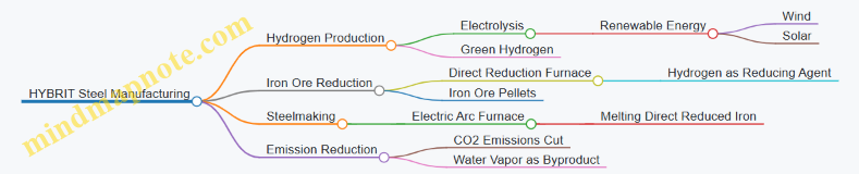
Engineering Best Practices in HYBRIT
Integration of Renewable Energy for Hydrogen Production
- Example: Vattenfall’s wind farms supply electricity for water electrolysis.
- Practice: Optimize electrolyzer operation to match variable renewable output, ensuring high efficiency and grid stability.
Direct Reduction Process Adaptation
- Example: Modifying existing direct reduction furnaces to operate with hydrogen instead of natural gas.
- Practice: Control gas flow and temperature precisely to maintain reduction kinetics and product quality.
Safety and Risk Management
- Example: Implementation of advanced hydrogen leak detection and ventilation systems.
- Practice: Conduct comprehensive hazard and operability studies (HAZOP) tailored to hydrogen’s properties.
Modular Pilot Plant Design
- Example: HYBRIT’s pilot plant designed for scalability and flexible operation.
- Practice: Use modular components to facilitate incremental capacity expansion and technology upgrades.
Detailed Mind Map: Engineering Challenges and Solutions
Real-World Example: Pilot Plant Operation
- Location: Luleå, Sweden
- Capacity: 1.3 MW electrolyzer producing hydrogen for direct reduction.
- Outcome: Demonstrated stable operation with 95% reduction of iron ore pellets using hydrogen.
- Lessons Learned: Importance of precise gas flow control and continuous monitoring to avoid process interruptions.
Environmental Impact
- CO2 Reduction: Potential to reduce steelmaking emissions by up to 90% compared to traditional blast furnace methods.
- Byproduct: Water vapor replaces CO2 as the main emission.
Economic Considerations
- Cost Drivers: Renewable electricity price, electrolyzer CAPEX, and hydrogen storage.
- Best Practice: Long-term power purchase agreements (PPAs) to stabilize electricity costs.
Summary
The HYBRIT project exemplifies how hydrogen energy systems engineering can revolutionize heavy industry by integrating clean energy technologies with traditional manufacturing processes. Its success hinges on multidisciplinary engineering approaches, rigorous safety practices, and strategic industrial deployment.
Additional Mind Map: Stakeholders and Project Management
This comprehensive view of the HYBRIT project provides energy engineers, hydrogen project managers, and clean energy developers with actionable insights and practical examples to guide similar decarbonization initiatives in the steel industry and beyond.
11.2 Hydrogen Fueling Infrastructure for Transportation
Hydrogen fueling infrastructure is a critical component in the adoption and scaling of hydrogen-powered transportation. This section explores the engineering, deployment, and best practices involved in establishing reliable, safe, and efficient hydrogen fueling stations for various transportation modes including passenger vehicles, buses, trucks, and trains.
Overview of Hydrogen Fueling Infrastructure
Hydrogen fueling stations provide compressed or liquefied hydrogen to fuel cell vehicles (FCVs). They typically include hydrogen production or delivery systems, compression, storage, and dispensing units. The infrastructure must ensure fast refueling times comparable to conventional fuels, high safety standards, and accessibility.
Key Components of a Hydrogen Fueling Station
Types of Hydrogen Fueling Stations
- On-site Production Stations: Produce hydrogen via electrolysis or reforming at the station.
- Delivered Hydrogen Stations: Receive hydrogen via tube trailers, pipelines, or liquid tankers.
Example: The Shell Hydrogen Station in California uses delivered compressed hydrogen stored onsite in high-pressure tanks.
Best Practices in Station Design and Deployment
- Safety First: Incorporate multiple layers of safety including hydrogen sensors, ventilation, and emergency shutdown systems.
- Standardization: Follow protocols such as SAE J2601 for fueling procedures to ensure compatibility and safety.
- User Experience: Design stations for quick and intuitive refueling, minimizing wait times.
- Scalability: Modular designs allow stations to expand capacity as demand grows.
Example: Toyota’s hydrogen stations in Japan employ standardized fueling protocols and advanced safety features, enabling rapid refueling times under 5 minutes.
Engineering Challenges and Solutions
- High-Pressure Compression: Achieving 700 bar fueling pressure requires robust compressors and storage.
- Thermal Management: Hydrogen cooling during fast fill to avoid overheating.
- Material Compatibility: Preventing hydrogen embrittlement in storage and dispensing components.
Example: The H2 Mobility network in Germany uses advanced compressor technology and cooling systems to maintain station reliability and safety.
Deployment Strategies
- Urban vs. Highway Stations: Urban stations focus on passenger cars and buses; highway stations cater to long-distance travel and heavy-duty trucks.
- Public-Private Partnerships: Collaboration between governments, automakers, and energy companies accelerates infrastructure rollout.
Example: California’s Hydrogen Highway initiative combined government incentives and private investment to establish over 40 stations.
Mind Map: Deployment Considerations
Case Study: California Hydrogen Fueling Network
- Background: California leads the US in hydrogen infrastructure with over 40 stations.
- Approach: Stations use delivered compressed hydrogen, standardized fueling protocols, and public-private partnerships.
- Outcome: Enabled deployment of thousands of fuel cell vehicles and buses.
Best Practice Highlight: Integration of real-time station monitoring and predictive maintenance reduced downtime and improved user confidence.
Future Trends
- Integration with Renewable Hydrogen: On-site electrolysis powered by solar or wind.
- Mobile Refueling Solutions: Hydrogen trailers to serve low-demand or remote areas.
- Digitalization: IoT and AI to optimize station operations and customer experience.
Summary
Hydrogen fueling infrastructure is foundational for the hydrogen transportation ecosystem. By adopting best practices in safety, standardization, and modular design, and learning from successful deployments like California and Japan, energy engineers and project managers can effectively plan and implement fueling stations that support the growing hydrogen vehicle market.
Additional Mind Map: Hydrogen Fueling Station Ecosystem
11.3 Large-Scale Ammonia Production Using Green Hydrogen
Ammonia (NH3) is a critical chemical widely used as a fertilizer and an emerging energy carrier. Traditionally, ammonia production relies heavily on fossil fuels, primarily through the Haber-Bosch process using hydrogen derived from natural gas (steam methane reforming). However, to achieve decarbonization goals, large-scale ammonia production using green hydrogen—hydrogen produced via renewable energy-powered electrolysis—is gaining momentum.
Overview of Green Ammonia Production
Green ammonia production involves two main steps:
- Green Hydrogen Production: Using renewable electricity (solar, wind, hydro) to electrolyze water, producing hydrogen without CO2 emissions.
- Ammonia Synthesis: Combining green hydrogen with nitrogen (extracted from air) in the Haber-Bosch process, powered ideally by renewable or low-carbon energy.
Mind Map: Green Ammonia Production Process
Best Practice: Integrating Renewable Energy with Ammonia Plants
Example: The Yara Pilbara Renewable Ammonia Project in Australia is a leading example of integrating large-scale solar and wind power with electrolyzers to produce green hydrogen, which feeds into an ammonia synthesis plant. This project demonstrates:
- Co-location of renewable energy generation and ammonia production to minimize transmission losses.
- Use of modular electrolyzers to scale hydrogen production based on renewable availability.
- Implementation of advanced process control to optimize energy consumption.
Key Engineering Considerations
- Electrolyzer Selection: PEM electrolyzers offer rapid response to fluctuating renewable inputs but are costlier; alkaline electrolyzers are more mature but less flexible.
- Energy Management: Balancing intermittent renewable supply with continuous ammonia synthesis demands energy storage or hybrid systems.
- Process Optimization: Heat integration and waste heat recovery improve overall plant efficiency.
- Safety: Handling large volumes of hydrogen and ammonia requires rigorous safety protocols.
Mind Map: Challenges and Solutions in Green Ammonia Production
Industrial Example: The H2U Eyre Peninsula Project (Australia)
- Project Scope: 20 MW electrolyzer powered by wind and solar to produce green hydrogen.
- Ammonia Production: Hydrogen combined with nitrogen to produce green ammonia for export.
- Innovations: Use of AI-driven predictive maintenance for electrolyzer reliability.
This project highlights the feasibility of green ammonia production at industrial scale, emphasizing the importance of renewable resource assessment and supply chain integration.
Environmental and Economic Impact
- Carbon Emissions: Green ammonia production can reduce CO2 emissions by up to 90% compared to conventional methods.
- Market Potential: Growing demand for green ammonia as fertilizer and as a carbon-free fuel for shipping and power generation.
- Economic Incentives: Governments and international bodies are providing subsidies and regulatory support to accelerate adoption.
Summary
Large-scale ammonia production using green hydrogen is a cornerstone for the future hydrogen economy. By leveraging renewable energy, advanced electrolyzer technologies, and optimized ammonia synthesis processes, the industry can transition toward sustainable and scalable ammonia production. Real-world projects like Yara Pilbara and H2U demonstrate best practices that combine engineering innovation with industrial deployment, paving the way for global decarbonization efforts.
11.4 Best Practice: Cross-Sector Collaboration for Hydrogen Ecosystem Development – Lessons from the Port of Rotterdam
The Port of Rotterdam stands as a pioneering example of how cross-sector collaboration can accelerate the development of a robust hydrogen ecosystem. This best practice section explores the strategic partnerships, integrated infrastructure, and multi-industry cooperation that have made the Port of Rotterdam a global leader in hydrogen deployment.
Overview
The Port of Rotterdam, Europe’s largest seaport, has leveraged its strategic location, industrial diversity, and stakeholder collaboration to build a comprehensive hydrogen ecosystem. This ecosystem integrates production, storage, transport, and end-use applications, involving sectors such as shipping, industry, energy, and logistics.
Key Elements of Cross-Sector Collaboration
- Stakeholder Engagement: Involving government bodies, private companies, research institutions, and local communities.
- Infrastructure Sharing: Utilizing existing pipelines, storage facilities, and transport networks.
- Regulatory Alignment: Coordinating policies and safety standards across sectors.
- Joint Investment: Pooling financial resources to reduce risks and increase scale.
- Knowledge Exchange: Sharing technical expertise and operational data.
Mind Map: Cross-Sector Collaboration Framework at Port of Rotterdam
Example 1: The NortH2 Project
The NortH2 initiative is a flagship project involving the Port of Rotterdam, aiming to produce green hydrogen at a massive scale using offshore wind power. This project exemplifies collaboration between renewable energy developers, port authorities, industrial users, and government agencies.
-
Collaboration Highlights:
- Shared investment in electrolyzer capacity.
- Integration with offshore wind farms.
- Coordination of hydrogen transport infrastructure.
-
Impact:
- Expected to produce up to 800,000 tons of green hydrogen annually by 2040.
- Supports decarbonization of heavy industry and shipping.
Example 2: Hydrogen Backbone Initiative
The Port of Rotterdam is a critical node in the European Hydrogen Backbone, a cross-border pipeline network designed to transport hydrogen efficiently across countries.
-
Collaboration Highlights:
- Harmonizing technical standards and safety protocols.
- Coordinating pipeline expansions with industrial demand.
- Joint planning with neighboring ports and countries.
-
Impact:
- Facilitates large-scale hydrogen trade.
- Enhances energy security and market liquidity.
Mind Map: Benefits of Cross-Sector Collaboration
Best Practices Derived from the Port of Rotterdam Experience
- Establish Clear Governance Structures: Define roles and responsibilities among stakeholders to streamline decision-making.
- Promote Transparency and Open Communication: Regular meetings and shared platforms help align objectives and resolve conflicts.
- Leverage Existing Infrastructure: Adapt and upgrade current assets to reduce CAPEX and accelerate deployment.
- Align Regulatory Frameworks: Work with policymakers to create enabling environments for hydrogen projects.
- Focus on Scalability and Flexibility: Design systems that can grow and adapt to evolving market and technology conditions.
- Encourage Innovation and Pilot Projects: Use demonstration projects to validate technologies and build confidence.
Conclusion
The Port of Rotterdam demonstrates that successful hydrogen ecosystem development hinges on robust cross-sector collaboration. By integrating diverse stakeholders, sharing infrastructure, and aligning policies, the port has created a scalable and sustainable hydrogen hub that can serve as a model for other regions worldwide.
Energy engineers, hydrogen project managers, and clean energy developers can draw valuable lessons from this approach to foster their own hydrogen initiatives, ensuring efficient deployment and long-term success.
12. Conclusion and Roadmap for Energy Engineers and Project Managers
12.1 Summary of Key Engineering Practices
In the rapidly evolving field of hydrogen energy systems engineering, mastering core engineering practices is essential for successful industrial deployment. This section summarizes the foundational practices that energy engineers, hydrogen project managers, and clean energy developers should integrate into their workflows.
System Design and Integration
- Holistic approach combining production, storage, transportation, and utilization.
- Modular design for scalability and flexibility.
- Integration with renewable energy sources to maximize green hydrogen production.
Example: The German modular hydrogen production facility employs standardized electrolyzer units that can be scaled up or down based on demand, reducing lead times and costs.
Safety Engineering and Risk Management
- Implementing rigorous hazard identification and mitigation strategies.
- Adhering to international safety standards (e.g., ISO/TC 197).
- Continuous safety training and emergency response planning.
Example: The Scandinavian industrial park integrates advanced hydrogen leak detection sensors and conducts quarterly emergency drills, significantly reducing incident response times.

Performance Optimization and Monitoring
- Utilizing real-time sensor data and AI-driven analytics for predictive maintenance.
- Employing digital twins to simulate and optimize system behavior.
- Regular performance benchmarking against industry standards.
Example: A Japanese hydrogen refueling station uses AI algorithms to predict fuel cell stack degradation, enabling preemptive maintenance and minimizing downtime.
Project Management and Stakeholder Engagement
- Conducting thorough feasibility studies and site assessments.
- Engaging regulatory bodies early to ensure compliance.
- Transparent communication with stakeholders to build trust.
- Securing financing through detailed economic analysis.
Example: The NortH2 project in the Netherlands exemplifies effective stakeholder collaboration, combining government, industry, and community input to streamline project execution.

Environmental Impact Assessment
- Performing life cycle assessments (LCA) to quantify environmental benefits.
- Minimizing carbon footprint through green hydrogen production.
- Planning for sustainable end-of-life management of system components.
Example: An Australian renewable-hydrogen hybrid system conducted a comprehensive LCA demonstrating a 70% reduction in greenhouse gas emissions compared to conventional energy sources.
Summary Table of Key Practices and Examples
| Engineering Practice | Key Actions | Example Project/Case Study |
|---|---|---|
| System Design & Integration | Modular design, renewable integration | German modular hydrogen production facility |
| Safety Engineering & Risk Mgmt | Leak detection, safety drills | Scandinavian industrial park |
| Performance Optimization & Monitoring | AI-driven predictive maintenance, digital twins | Japanese hydrogen refueling station |
| Project Management & Stakeholder Engagement | Feasibility, regulatory compliance, financing | NortH2 project, Netherlands |
| Environmental Impact Assessment | Life cycle assessment, carbon footprint reduction | Australian renewable-hydrogen hybrid system |
By embedding these engineering practices into hydrogen energy projects, professionals can ensure safer, more efficient, and environmentally responsible deployments that accelerate the transition to a clean energy future.
12.2 Strategic Planning for Hydrogen Project Success
Strategic planning is a cornerstone for the successful deployment of hydrogen energy projects. Given the complexity, capital intensity, and evolving regulatory landscape of hydrogen systems, a well-structured strategic plan helps project managers and energy engineers navigate technical, financial, and operational challenges effectively.
Key Components of Strategic Planning for Hydrogen Projects
- Vision and Objectives: Define clear, measurable goals aligned with broader energy transition targets.
- Stakeholder Analysis: Identify and engage all relevant parties including government bodies, investors, technology providers, and local communities.
- Technology Selection: Choose appropriate hydrogen production, storage, and utilization technologies based on site-specific factors.
- Risk Assessment and Mitigation: Evaluate technical, financial, environmental, and regulatory risks.
- Financial Planning: Develop detailed CAPEX/OPEX models, funding strategies, and economic feasibility.
- Regulatory Compliance: Understand and plan for permits, safety standards, and environmental regulations.
- Project Timeline and Milestones: Establish realistic schedules with critical path analysis.
- Monitoring and Evaluation: Set KPIs and feedback loops for continuous improvement.
Mind Map: Strategic Planning Framework for Hydrogen Projects
Example 1: Strategic Planning in the NortH2 Project (Netherlands)
The NortH2 project, aiming to produce green hydrogen at a large scale using offshore wind power, exemplifies strategic planning excellence:
- Vision & Objectives: Produce 4 GW of green hydrogen by 2030 to decarbonize industry and transport.
- Stakeholder Engagement: Collaboration between multiple energy companies, government, and research institutions.
- Technology Selection: Focus on PEM electrolysis integrated with offshore wind farms.
- Risk Management: Comprehensive environmental impact studies and phased deployment to mitigate technical risks.
- Financial Planning: Combination of private investment and government subsidies.
- Regulatory Compliance: Early engagement with regulators to streamline permitting.
- Project Scheduling: Clear milestones for pilot, demonstration, and full-scale phases.
- Monitoring & Evaluation: Use of digital twins and real-time data analytics to optimize operations.
This strategic approach has positioned NortH2 as a flagship project in Europe’s hydrogen roadmap.
Mind Map: Risk Management in Hydrogen Project Planning
Example 2: Risk Mitigation in a Modular Hydrogen Plant in Germany
A modular hydrogen production facility in Germany implemented strategic risk mitigation by:
- Conducting pilot testing of electrolyzer modules before full deployment.
- Engaging local authorities early to address permitting challenges.
- Structuring financing with contingency reserves to manage cost uncertainties.
- Implementing robust safety training programs to minimize operational risks.
This proactive planning reduced delays and enhanced stakeholder confidence.
Practical Tips for Energy Engineers and Project Managers
- Start Early with Stakeholder Engagement: Early dialogue helps identify concerns and build partnerships.
- Use Scenario Planning: Develop multiple project scenarios to prepare for uncertainties.
- Leverage Digital Tools: Utilize project management software and simulation tools for planning and monitoring.
- Focus on Modular and Scalable Designs: Enables flexibility and phased investment.
- Prioritize Safety and Environmental Compliance: Integral to project acceptance and longevity.
Mind Map: Financial Planning Essentials
Example 3: Financial Strategy in Australia’s Renewable Hydrogen Project
An Australian renewable hydrogen project combined:
- Government grants targeting clean energy innovation.
- Private sector investment from energy companies.
- Detailed economic modeling to demonstrate long-term viability.
This diversified financial strategy ensured project resilience against market fluctuations.
Summary
Strategic planning for hydrogen projects requires a multi-disciplinary approach integrating technical, financial, regulatory, and stakeholder considerations. By applying structured frameworks, leveraging best practices, and learning from successful examples, energy engineers and project managers can significantly enhance the likelihood of project success and contribute meaningfully to the clean energy transition.
12.3 Building Competencies and Training for the Hydrogen Economy
As the hydrogen economy rapidly expands, the demand for skilled professionals in hydrogen energy systems engineering and deployment grows exponentially. Building competencies and providing targeted training programs are essential to ensure a workforce capable of designing, operating, and maintaining hydrogen infrastructure safely and efficiently.
Key Competency Areas for Hydrogen Professionals
To effectively contribute to the hydrogen sector, energy engineers, project managers, and developers must develop expertise across multiple domains. Below is a mind map outlining the core competency areas:
Training Program Examples
-
Modular Training for Electrolyzer Operation and Maintenance
- Objective: Equip technicians with hands-on skills to operate and maintain PEM electrolyzers.
- Format: Combination of classroom theory, virtual simulations, and on-site practical sessions.
- Example: A European hydrogen plant partnered with a technical institute to deliver a 6-week certification program, resulting in a 30% reduction in downtime due to improved maintenance practices.
-
Project Management Workshops Focused on Hydrogen Infrastructure
- Objective: Develop project managers’ ability to handle hydrogen-specific challenges such as regulatory navigation and stakeholder coordination.
- Format: Case study discussions, role-playing exercises, and expert lectures.
- Example: The NortH2 project in the Netherlands conducted quarterly workshops for their project leads, improving project delivery timelines by 15%.
-
Safety and Emergency Response Drills
- Objective: Train operational staff on hydrogen-specific safety protocols and emergency procedures.
- Format: Scenario-based drills, safety audits, and certification.
- Example: A Scandinavian industrial park implemented annual drills, which enhanced emergency response times and reduced incident rates.
Mind Map: Training Delivery Methods
Building a Continuous Learning Culture
To keep pace with evolving hydrogen technologies, organizations should foster a culture of continuous learning:
- Regular Skill Assessments: Identify gaps and tailor training accordingly.
- Knowledge Sharing Platforms: Internal wikis, forums, and lunch-and-learns.
- Partnerships with Academic and Research Institutions: Collaborate on curriculum development and research projects.
- Encouraging Certifications and Advanced Degrees: Support employees pursuing specialized hydrogen energy credentials.
Example: Cross-Industry Competency Development
The Port of Rotterdam’s hydrogen ecosystem initiative exemplifies cross-sector competency building by:
- Hosting joint training sessions for maritime, chemical, and energy sector professionals.
- Developing standardized hydrogen safety certifications recognized across industries.
- Facilitating knowledge exchange workshops to accelerate innovation adoption.
By systematically developing competencies through structured training programs and fostering continuous learning, the hydrogen sector can build a robust workforce capable of driving the clean energy transition forward.
12.4 Best Practice: Continuous Improvement and Innovation – Framework for Long-Term Industrial Deployment
Long-term success in hydrogen energy systems engineering and industrial deployment hinges on a robust framework for continuous improvement and innovation. This approach ensures that projects remain efficient, cost-effective, safe, and aligned with evolving technologies and market demands.
Key Elements of Continuous Improvement and Innovation Framework
Example: Continuous Improvement at a European Green Hydrogen Plant
A green hydrogen facility in Germany implemented a continuous improvement cycle by integrating advanced sensor networks and AI-driven analytics to monitor electrolyzer performance. This enabled early detection of degradation, reducing downtime by 15% over one year. Regular training sessions ensured operators adapted quickly to new technologies, fostering a proactive safety culture.
The plant also established a cross-functional innovation team that collaborated with local universities to pilot novel catalyst materials, improving electrolyzer efficiency by 5%.
Mind Map: Continuous Improvement Cycle in Hydrogen Plants

Innovation Integration Example: Digital Twins for Predictive Maintenance
Digital twin technology creates a virtual replica of hydrogen plants, enabling simulation of operational scenarios and predictive maintenance scheduling. For instance, a Japanese hydrogen refueling station used digital twins to reduce unexpected equipment failures by 30%, optimizing maintenance costs and improving reliability.
Mind Map: Innovation Adoption Process
Best Practice Recommendations
- Establish a dedicated continuous improvement team with cross-disciplinary expertise.
- Leverage data analytics and AI to gain actionable insights.
- Foster partnerships with academic and research institutions for innovation.
- Promote a culture of safety and learning through regular training.
- Document lessons learned and update operational procedures accordingly.
- Use modular and standardized designs to facilitate scaling and replication.
- Engage stakeholders regularly to maintain transparency and trust.
By embedding continuous improvement and innovation into the core of hydrogen energy projects, energy engineers and project managers can ensure sustainable, efficient, and safe industrial deployment that evolves with technological advancements and market needs.