Backyard Greywater Systems Made Simple
1. Understanding Greywater and Where It Comes From
1.1 Defining Greywater and Separating It from Blackwater
Greywater is wastewater from household activities that are generally less contaminated than toilet waste. In most homes, it comes from sinks, showers, and laundry. Blackwater is wastewater from toilets and urinals, which carries higher loads of pathogens and requires a different handling approach.
A useful way to think about separation is “source first, then treatment.” You don’t start by treating everything the same and hoping for the best. Instead, you identify where the water came from, estimate what it likely contains, and then route it to the right system.
What Counts as Greywater
Greywater typically includes:
- Laundry water from washers, which can contain detergents, lint, and body oils.
- Bath and shower water from rinsing skin and hair.
- Bathroom sink water from handwashing and brushing.
- Kitchen sink water is sometimes treated as greywater in practice, but it depends on local rules and how much grease or food residue enters the drain.
Greywater is not “clean water.” It’s “lower risk water” relative to blackwater, and it still needs controls for solids, odors, and microbial growth.
What Counts as Blackwater
Blackwater includes:
- Toilet and urinal waste.
- Any wastewater that has mixed with toilet waste.
Once greywater and blackwater mix, the combined stream usually must be handled as blackwater. That’s why separation is not just a design preference; it’s a safety boundary.
Why Separation Matters
Separation reduces both health risk and system complexity. If you keep streams apart, you can use treatment levels that match the actual contamination level. You also avoid overloading a greywater treatment setup with solids and pathogens that belong in the sewer or a properly permitted onsite wastewater system.
A practical example: if a diverter valve sends laundry water to a garden system, but a toilet backup or cross-connection sends toilet waste into the same line, the garden system becomes the wrong place for that contamination. Separation prevents that mismatch.
The Greywater Spectrum and “Edge Cases”
Not all greywater is equal. The “grey” category covers a range of contamination.
- Lower solids: shower water without heavy hair shedding.
- Higher solids: laundry water with lint.
- Potentially higher organics: kitchen sink water when food particles or grease are common.
Edge cases often come from what goes down the drain:
- Disposable wipes can behave like solids and clog filters.
- Harsh chemicals from cleaning products can harm biological treatment media.
- Large volumes of disinfectants can reduce microbial activity in treatment components.
The safest approach is to treat the greywater source list as a design input, not an afterthought.
How to Separate in Real Plumbing Terms
Separation is achieved through routing and physical separation of piping.
- Dedicated greywater piping: greywater lines run separately from the blackwater sewer line.
- No cross-connections: there should be no shared fittings that allow backflow or mixing.
- Backflow prevention: when pressure changes occur, devices and air gaps prevent sewage from moving backward.
A simple household check: trace each fixture to its drain line. If you can’t clearly identify where a fixture’s wastewater goes, you can’t reliably separate it.
Mind Map: Greywater Versus Blackwater
Example: Two Fixtures, Two Outcomes
Consider a home with a laundry-to-garden plan.
- Laundry water goes to a treatment and distribution line. The system is sized for intermittent loads and includes filtration to handle lint.
- Toilet waste goes to the sewer. The greywater line never shares a connection point with the toilet line.
If a plumber later adds a “temporary” tee fitting to connect a drain, that small change can break the separation boundary. The correct fix is to route the new connection into the appropriate stream with proper backflow protection.
Example: Kitchen Sink as a Decision Point
A kitchen sink can be treated as greywater in some jurisdictions, but it depends on how the sink is used.
- If the sink mostly handles rinsing and minimal grease, the greywater load may be manageable with filtration.
- If grease and food scraps frequently enter the drain, the system needs stronger solids and grease handling, or the kitchen sink may be excluded from greywater routing.
Separation is therefore both a plumbing task and a household behavior match: the system should reflect what actually goes down the drain.
1.2 Common Greywater Sources in Homes and Typical Use Patterns
Greywater is the wastewater from certain household fixtures that is not toilet waste. In practice, the “source” matters because each fixture produces a different mix of water volume, temperature, solids, grease, and cleaning chemicals. Those differences drive how you route, treat, and reuse the water safely.
Common Greywater Sources
Laundry (Washing Machine) Laundry greywater is usually the largest and most consistent stream. It tends to be warm, contains lint and fine solids, and may include detergents, fabric softeners, and occasional stain removers. Typical use patterns are spiky: a few loads per day, often at predictable times.
Showers and Bathtubs Shower and bath water is often moderate in volume and typically lower in solids than laundry. It can carry skin oils, hair, and soap residue. Temperature is usually warm, which can affect biological activity in storage and distribution.
Bathroom Sinks Sink water is usually smaller in volume but can be chemically “busy,” especially with toothpaste, shaving products, and hand soaps. Solids are generally low, but the concentration of oils and surfactants can be noticeable.
Kitchen Sinks Kitchen sink water is sometimes included in greywater systems, but it is often the trickiest. Food particles, grease, and higher organic load can increase clogging and odor risk. If your local rules allow it, it usually requires stronger solids management and grease-aware design.
Other Fixtures Examples include washing machine overflow, floor drains in some jurisdictions, and utility sinks. These can be greywater or not depending on what they connect to and what they carry.
Typical Use Patterns That Affect Design
1. Volume and timing Laundry loads create short bursts of flow. Showers create more frequent, smaller bursts. If you design for steady flow but your household uses water in bursts, filters and storage can either overflow or sit idle.
2. Solids and clogging risk Hair and lint are common culprits. A shower drain can contribute hair that tangles and slows flow, while laundry lint can accumulate in filters. Kitchen drains add food fines and grease that can coat media and reduce performance.
3. Chemical variability Detergent strength changes with load size and product type. Some households use harsher cleaners occasionally, such as for deep cleaning. Even without “bad” products, the concentration can shift from day to day.
4. Temperature and odor control Warm water supports microbial growth. If greywater sits too long, it can develop odor and biofilm. That’s why routing and storage strategy matter as much as treatment.
Mind Map: Greywater Sources and What They Carry
Integrated Examples from Realistic Household Patterns
Example: Laundry-Only Reuse Plan A household runs 2–4 wash loads on weekdays, mostly in the late morning and early evening. Laundry greywater is routed to a filter and then to a subsurface distribution zone. Because the stream is predictable, the system can be sized around typical load frequency, and maintenance intervals can align with how often lint accumulates.
Example: Bathroom-Focused Reuse Plan Another household uses showers more than baths and has fewer laundry loads. Greywater routing targets shower drains and a portion of sink water. The design emphasizes hair capture and easy access for cleaning, since small, frequent flows can still bring enough hair to clog distribution if not managed.
Example: Mixed Sources With Kitchen Exclusion A home wants to reuse laundry and shower water but not kitchen sink water. The plumbing layout keeps kitchen drains separate, reducing grease and food fines entering the greywater path. This simplifies filtration requirements and lowers the chance of odor from organic buildup.
Quick Source-to-Pattern Summary
- Laundry: predictable bursts, lint, detergents.
- Showers/Baths: frequent moderate flows, hair and oils.
- Sinks: smaller flows, soaps and personal care chemicals.
- Kitchen: often higher solids and grease, more demanding treatment.
Understanding these sources and patterns early prevents mismatches later, like using a filter meant for hair when the stream is mostly lint, or storing warm water longer than necessary.
1.3 Water Quality Differences Between Laundry and Other Greywater Streams
Greywater is not one uniform liquid. “Grey” is a category, not a chemical identity, and different household sources carry different mixes of soap, lint, food particles, grease, and microbes. That matters because treatment and reuse success depend on what you’re actually collecting.
What Changes Between Laundry and Other Greywater
Laundry water usually contains the highest load of suspended solids and surfactants. Surfactants are the cleaning agents that help lift oils and dirt, but they also change how water behaves in filters and soil. Laundry also tends to include lint and fine fibers that can clog media beds and reduce infiltration if not managed.
Other greywater streams—like bathroom sinks, showers, and bathtubs—often have lower solids but can still carry skin oils, hair, and small amounts of soap residue. Kitchen sink water is a special case: it can include food particles and grease, which are not typical in most laundry-only setups and can overwhelm simple treatment trains.
A Practical Comparison by Source
Laundry loads are driven by detergent type, wash temperature, and whether the load includes heavily soiled items. A “normal” load of lightly soiled clothing might produce greywater that filters easily and smells less, while a load with heavy soil or oily fabrics can increase both organic load and odor potential.
Bathroom streams are often dominated by personal care products. Even when the water looks clear, it can contain oils and emulsifiers that affect how quickly biofilm forms in pipes and distribution lines. Showers and bathtubs also contribute hair, which can bridge or mat in some filters.
Kitchen streams can be the most variable. Even small amounts of cooking residue can create grease films that reduce oxygen transfer in treatment components and can cause surface slicks if reused improperly.
Mind Map: Quality Drivers and Their Effects
How These Differences Show Up in Design Decisions
If you design a system for laundry greywater, you plan for solids control as a first priority. That usually means screening and filtration sized to catch lint and fibers before water reaches media beds or subsurface distribution. You also plan for more frequent maintenance because detergent and fine solids accumulate.
For bathroom greywater, you can often use simpler solids removal, but you still design for biological stability. That means preventing long stagnation in tanks, using appropriate flow paths, and ensuring the distribution system can handle periodic surges without creating anaerobic zones.
For kitchen greywater, many residential reuse approaches either exclude it or require a more robust treatment train. Grease can coat surfaces and reduce infiltration, and food particles can create rapid clogging. Even when local rules allow reuse, the system must be built to handle the higher organic and fat content.
Example: Laundry-Only vs Mixed Greywater
Imagine two backyards with similar soil and similar garden goals.
In the laundry-only setup, the system receives intermittent bursts from washing machines. The design focuses on a filter that can capture lint and a storage or equalization step that smooths flow. Maintenance is scheduled around filter cleaning because the solids load is predictable.
In the mixed setup that includes shower and sink water, the solids load is lower, but the system must manage oils and soap residue. The distribution lines may develop biofilm if water sits too long, so the design emphasizes minimizing dead zones and ensuring consistent turnover.
If kitchen water is added to the mix, the same filter and distribution approach may fail sooner. Grease can cause surface problems and clogging that looks different from lint-driven clogging. That’s why many designs treat kitchen greywater as a separate stream or exclude it from reuse.
Example: Interpreting “Looks Clean” Water
Clear water can still be high in surfactants or oils. A bathroom sink can drain with little visible debris, yet still leave residues that encourage biofilm. Laundry water can look cloudy due to fine fibers, but the bigger issue is how those fibers behave in the treatment path. In both cases, the design should be based on source characteristics, not appearance.
Summary of Key Differences
Laundry greywater typically brings more surfactants and fine solids, pushing designs toward stronger solids control and maintenance. Bathroom greywater often has lower solids but more oils and soap residue, pushing designs toward biological stability and good flow management. Kitchen greywater is the most variable and grease-prone, often requiring exclusion or a more demanding treatment approach.
1.4 Health and Hygiene Basics for Backyard Reuse Systems
Backyard greywater reuse can be safe when you treat it like a plumbing system with hygiene rules, not like a “free water” shortcut. The core idea is simple: greywater is not sterile, so your design and habits must prevent exposure and keep the system from becoming a nuisance.
What “Safe” Means in Practice
Safety is about controlling three things: contact, contamination spread, and system failure. Contact control means people and pets should not touch treated water or wet surfaces. Contamination spread control means you prevent cross-connections with potable water and keep greywater from reaching food crops or drinking sources. System failure control means you design for clogs, overflows, and power interruptions so the system fails in a predictable, manageable way.
A practical rule of thumb: if you wouldn’t want to drink it, you shouldn’t allow it to splash, aerosolize, or run where kids, pets, or food preparation surfaces can contact it.
Hygiene Zones and Exposure Pathways
Think in zones. The “dirty side” includes the greywater plumbing, treatment components, and any distribution lines that carry untreated or partially treated water. The “clean side” includes potable plumbing, indoor fixtures, and areas where people walk barefoot.
Exposure pathways are usually one of these:
- Direct contact: hands, feet, or clothing touching wet soil or hoses.
- Splash and spray: runoff from uneven ground or pressurized outlets.
- Surface contamination: greywater reaching patios, play areas, or garden paths.
- Cross-connection: backflow from greywater lines into potable supply.
Design choices reduce these pathways. For example, subsurface distribution reduces splash risk, while well-labeled valves and physical separation reduce cross-connection risk.
Cross-Connection Prevention and Backflow Control
Cross-connections are the most serious hygiene threat because they can move greywater into drinking water. Even a small backflow event can defeat all other precautions.
Use backflow prevention devices where required by local code, and ensure they are installed correctly and maintained. Also prevent “accidental mixing” by keeping greywater piping clearly identified and physically separated from potable lines. If you ever have to guess which pipe is which, you’re already behind on hygiene.
Handling Laundry Greywater Responsibly
Laundry greywater is often the easiest stream to manage, but it still contains detergents, lint, and variable organic load.
Hygiene best practices:
- Use low-suds, biodegradable detergents when possible to reduce foaming that can interfere with treatment and pumping.
- Avoid bleach and harsh chemicals unless your system is specifically designed to handle them, because they can disrupt biological treatment and increase maintenance.
- Manage lint with appropriate filtration so solids don’t clog distribution and force you into messy, frequent cleanouts.
Concrete example: if you notice frequent filter clogging after switching to a detergent with higher residue, treat it as a hygiene signal. Clean the filter, check flow, and adjust detergent choice rather than letting the system run “until it clears.”
Odor, Biofilm, and What They Indicate
Odor is not just unpleasant; it’s a clue that the system is accumulating organics or experiencing stagnant zones. Biofilm is normal in many treatment environments, but excessive buildup can cause reduced flow, channeling, and surface wetting.
Hygiene actions when odors appear:
- Check for standing water near distribution areas.
- Inspect filters and screens for solids accumulation.
- Verify flow paths so water doesn’t bypass treatment.
- Confirm vents and drainage are functioning so gases can escape safely.
A simple observation-based approach works: if the system smells worse after a particular laundry cycle, the issue is likely load-related (detergent, solids, or flow rate), not a mysterious “mood” of the soil.
Safe Distribution Habits
Even with good treatment, distribution must prevent contact. Keep greywater away from:
- Food crops that are eaten raw.
- Areas where people sit, play, or walk barefoot.
- Any location where runoff can reach sidewalks, driveways, or storm drains.
Prefer subsurface distribution or controlled application methods that minimize wetting of surfaces. If you use surface application, do it in a way that avoids pooling and ensures water infiltrates quickly.
Mind Map: Health and Hygiene Controls
Quick Example Scenarios
Scenario 1: Filter clogs after detergent change. Clean the filter, check flow, and switch to a lower-residue detergent. Hygiene improves because solids are less likely to cause backups and surface wetting.
Scenario 2: You see wet patches near the distribution area. Treat it as a distribution failure, not a “soil soaking” bonus. Reduce application rate, check emitter spacing or subsurface depth, and confirm the system isn’t bypassing treatment.
Scenario 3: A hose is used to “test” flow. Don’t. Testing should be done with controlled methods that avoid splashing and contact. Hygiene is easier when you never create unnecessary exposure in the first place.
Summary Checklist for Everyday Hygiene
Keep greywater separated from potable water, control contact by design, maintain filters and flow paths, and treat odors or wet surfaces as actionable signals. If the system is clean, controlled, and predictable, hygiene follows.
1.5 What You Can and Cannot Reuse in Residential Settings
Greywater reuse is mostly a question of matching water quality to a safe use. The “grey” part is not a guarantee of cleanliness; it’s a hint that the water has fewer hazards than blackwater, but still carries soaps, food particles, lint, and microbes. A practical rule is to reuse greywater only where local codes allow, and only in ways that keep it away from people’s mouths and from areas where it can easily spread onto surfaces.
Core Principle for Safe Reuse
Think in three layers: source, treatment, and destination. If any layer is weak, the system becomes harder to keep safe. For example, laundry water often has more detergent and lint than a bathroom sink stream, so it typically needs more solids control. Even well-treated water should still be directed to non-potable uses like irrigation, where contact is limited and the soil can act as part of the treatment process.
What You Can Usually Reuse
In many residential setups, the most straightforward reuse is subsurface irrigation of landscaping using treated laundry or combined greywater, depending on local rules. Subsurface delivery reduces the chance of overspray and surface wetting, which matters because wet surfaces can spread microbes and create odors.
Common allowed uses often include:
- Landscape irrigation with treated greywater, especially subsurface distribution.
- Tree and shrub watering where water is applied below the surface or in controlled, low-splash ways.
- Soil-based absorption systems that rely on filtration and controlled loading.
A simple example: a laundry-only system that filters out lint, stores briefly for flow smoothing, and then distributes through drip lines buried a few inches can be a good match for shrubs. The plants get water, and the system avoids creating puddles.
What You Typically Cannot Reuse
Many restrictions are about preventing direct human exposure. Even if greywater looks clear, it can contain pathogens and chemical residues.
Common “do not reuse” categories include:
- Drinking or cooking uses, including making ice or filling water features that humans contact.
- Handwashing, toilet flushing, or bathing unless a code-approved, fully separated, and specifically permitted non-potable pathway exists.
- Watering edible crops in ways that allow contact with edible portions, unless your jurisdiction explicitly permits it and you meet the required treatment level.
- Any use that creates aerosols (mist, spray, or splashing) where people might inhale droplets.
- Direct discharge to storm drains or surface runoff where it can spread beyond the intended treatment area.
A concrete example: using a greywater hose to spray a lawn on a hot day may feel efficient, but it increases surface wetting and aerosol risk. Even if the water is filtered, the delivery method can undermine safety.
How Treatment Level Changes the Allowed Destination
Treatment is not just about “making it cleaner.” It changes what risks are reduced.
- Solids control (screens, settling, or filtration) helps prevent clogging and reduces the organic load that fuels odors and biofilm.
- Biological treatment or soil absorption helps manage microbes when the system is designed for controlled infiltration.
- Disinfection may be required for certain reuse destinations, particularly where contact risk is higher.
Example: If you plan to irrigate subsurface, you may be able to use a system that emphasizes filtration and controlled distribution. If you plan to irrigate closer to the surface or in a way that increases contact risk, the required treatment level usually becomes more stringent.
Mind Map: Reuse Decisions at a Glance
Practical “Can I Use This Water Here?” Checklist
Before you connect anything, verify four items in order: (1) your greywater source is permitted for reuse, (2) your treatment matches the destination’s risk level, (3) your delivery method avoids aerosols and surface wetting, and (4) the system prevents backflow and cross-connections.
Example: Suppose you want to water shrubs near a driveway. If your system is designed for subsurface drip and includes filtration to handle lint, the destination is typically a good match. If instead you plan to run a surface emitter that leaves wet leaves and soil splashes, you’re changing the risk profile without changing the treatment, which is where problems start.
In short, safe residential reuse is less about “greywater being okay” and more about designing the whole path so the destination never receives more risk than it can handle.
2. Checking Local Rules and Choosing a Compliant Approach
2.1 How to Find Applicable Regulations for Greywater Reuse
Greywater rules are local, not universal. The fastest way to get to a compliant design is to treat regulations like a checklist: identify the governing authority, determine which fixtures count as greywater, then match your proposed reuse method to the allowed treatment and discharge rules.
Start with the Governing Authority
Begin by locating the agency that regulates onsite plumbing and water reuse in your area. In many places, that’s a combination of building departments, public health departments, and water utilities. If you’re unsure, call the building department and ask which office handles “onsite greywater reuse” or “alternative wastewater systems.” Keep notes on the exact wording they use; it helps when you later compare your plan to their requirements.
Next, confirm whether your project is handled as a standard plumbing permit, an onsite wastewater permit, or a special reuse approval. The permit pathway matters because it determines which standards you must meet and which inspections you’ll face.
Identify What Your System Is Allowed to Reuse
Regulations usually define greywater by source and by what it can be used for. Common categories include laundry-only greywater and “all greywater except toilets.” Your design may be limited to irrigation, subsurface irrigation, or specific landscape types.
A practical way to avoid surprises is to list every fixture you plan to connect, then map each one to the definition used in your jurisdiction. For example, if your plan includes a kitchen sink, you may discover that many rules exclude it or require a higher treatment level.
Determine the Allowed End Uses
Even when greywater reuse is permitted, the allowed destination can be narrow. Typical restrictions include:
- Irrigation only, with limits on spray versus subsurface application
- No reuse for edible crops
- No discharge to surface runoff or storm drains
- Setbacks from wells, property lines, and buildings
Write these as “musts” and “must nots” before you size anything. If you decide later to switch from subsurface to surface application, you may have to redo treatment and setback calculations.
Match Treatment Requirements to Your Reuse Method
Rules often specify treatment levels in plain terms, such as screening, filtration, disinfection, or “equivalent treatment.” The key is to translate those requirements into design actions.
For instance, if your jurisdiction requires filtration before subsurface distribution, you’ll need to ensure your system includes a filter sized for your expected flow and that maintenance access is built in. If disinfection is required, you’ll need to confirm whether the rule expects a chemical disinfectant, UV, or another method, and whether it requires specific contact times or performance verification.
Confirm Setbacks, Separation, and Discharge Controls
Setbacks are where many otherwise-good designs fail. Regulations may require minimum distances from:
- Wells and groundwater recharge areas
- Foundations and crawl spaces
- Property lines and easements
- Water meters, septic systems, and storm drains
They may also require separation between the treated water and the receiving soil zone, plus controls to prevent surfacing. A simple test during planning is to sketch your yard with the setbacks as shaded bands. If the shaded bands swallow your preferred location, you’ll know early that you must change the layout.
Verify Plumbing Safety Requirements
Even when reuse is allowed, cross-connection prevention is non-negotiable. Look for requirements related to:
- Backflow prevention between greywater and potable lines
- Dedicated piping identification and labeling
- Diverter valves that prevent accidental mixing
- Prohibitions on connecting to toilets or drains that serve blackwater
A good sign is when the rules clearly describe how to prevent “wrong-way flow.” If the language is vague, ask the permitting office how they interpret it for inspections.
Use a Practical Document Checklist
Before you draft the system, gather the documents you’ll need to reference during design and permitting. A checklist keeps you from chasing the same question twice.
- Jurisdiction name and permit type
- Greywater definition by fixture source
- Allowed end uses and restrictions
- Required treatment steps and performance expectations
- Setbacks and separation distances
- Inspection requirements and required drawings
- Operation and maintenance expectations
Mind Map: Finding Regulations Step by Step
Example: Laundry-Only System in a Tight Yard
Suppose you want to reuse laundry water for subsurface irrigation. You confirm the local rule allows laundry-only greywater for subsurface distribution. The rule requires filtration and prohibits surface runoff. When you check setbacks, you find the required distance from a nearby well leaves only one narrow strip of yard. You redesign the layout to keep the distribution field inside that strip and add cleanouts for maintenance. The system becomes compliant not because the treatment changed, but because the setbacks were handled early.
Example: Adding a Kitchen Sink Changes Everything
You initially plan to include a kitchen sink because it’s “greywater.” During your definition check, you learn the jurisdiction excludes kitchen sink water or requires additional treatment beyond what laundry-only systems need. You either remove the kitchen connection or redesign the treatment train to meet the higher requirement. The lesson is simple: fixture scope drives the regulation scope.
Example: When the Rule Mentions Treatment but Not the Method
Some rules state that greywater must receive “equivalent treatment” without naming a specific technology. In that case, you ask the permitting office what they accept during inspection, and you document your design basis in your submittal. You’re not guessing; you’re aligning your design with how the authority evaluates compliance.
Quick Summary of the Workflow
Find the authority, confirm the permit pathway, list your fixtures, match your end use, translate treatment language into components and maintenance, then apply setbacks and safety controls. If you do those steps in order, the rest of the design work stays grounded in what’s actually allowed.
2.2 Understanding Permit Requirements and Inspection Expectations
Greywater rules are local, but the logic behind them is consistent: protect public health, prevent cross connections, and keep water where it belongs. Before you design anything, treat permitting as part of the engineering process, not a paperwork afterthought.
Start with the Jurisdiction and the Reuse Goal
Permits usually hinge on two questions: where you live and what you plan to do with the water. Start by identifying the authority that governs onsite plumbing and water reuse. Then translate your goal into a reuse category, such as laundry-only reuse, subsurface irrigation, or surface application. A system that looks similar on paper can fall under different rules depending on whether it discharges below grade, uses a diverter, or includes disinfection.
Example: If your plan is “laundry to subsurface irrigation,” you may need fewer steps than “laundry plus kitchen to surface irrigation,” because the latter typically involves higher contamination risk and stricter controls.
Understand What Triggers Review
Most jurisdictions review projects when they involve new plumbing connections, new treatment components, or changes to drainage pathways. Common triggers include:
- New or modified piping that carries non-potable water
- Installation of tanks, filters, pumps, or disinfection units
- Any system that could contact soil surface, groundwater, or potable plumbing
- Changes to setbacks, easements, or discharge points
Example: Replacing a failed laundry diverter with the same model may be treated as maintenance, while rerouting the greywater line to a new garden zone is usually treated as a new installation.
Know the Typical Permit Package
Even when forms differ, the review package often asks for the same evidence. Expect to provide:
- A site plan showing property boundaries, structures, and reuse areas
- A plumbing diagram showing source fixtures, diverter/control logic, treatment, and distribution
- Component specifications for tanks, filters, pumps, and any disinfection method
- A maintenance plan describing how you will keep the system working
- A description of how you prevent cross connections and backflow
Example: If you show a filter and pump on the diagram but cannot explain how you will clean the filter and manage solids, reviewers may require additional detail because performance depends on maintenance.
Learn the Inspection Expectations
Inspections typically occur at two stages: before concealment and after commissioning. The “before concealment” visit focuses on safety and correct routing, since trenches and walls hide mistakes. The “after commissioning” visit checks that the system operates as intended.
What inspectors commonly verify:
- No cross connections to potable water or blackwater lines
- Correct installation of backflow prevention and air gaps where required
- Proper slope, pipe sizing, and secure fittings
- Correct placement and labeling of non-potable components
- Evidence that controls divert flow correctly and fail safely
Example: If your diverter is supposed to send greywater to the treatment unit but is installed backward, the system may still run—yet it could discharge where it shouldn’t. Inspectors look for these “it works, but wrong” failures.
Prepare for Common Correction Requests
Reviewers often request clarifications rather than rejecting projects outright. The most frequent correction themes are:
- Missing or unclear diagrams, especially around valves and diversion points
- Insufficient detail on how overflow or bypass is handled
- Distribution layouts that risk surface wetting or ponding
- Lack of access for maintenance, such as cleanouts or filter service space
Example: If your distribution line ends near a walkway, you may be asked to adjust the layout or add a method to prevent surfacing, because inspectors care about where water can appear during high-use days.
Mind Map: Permit and Inspection Workflow
Example: A Practical Permit Checklist for a Laundry-Only Subsurface System
Use this as a sanity check before submitting:
- Site plan includes reuse zone boundaries and distances to structures
- Plumbing diagram shows laundry fixtures feeding a diverter, then treatment, then subsurface distribution
- Backflow prevention method is identified and shown in the diagram
- Filter and pump locations include service access dimensions
- Overflow path is defined and routed to an approved alternative
- Maintenance tasks are described in plain language (what you clean, how often, and what you replace)
Example: If your plan includes a pump, the checklist should also include how you will prevent airlocks and how you will confirm flow after filter cleaning, because inspectors expect systems to be serviceable, not mysterious.
Example: What to Bring to an Inspection
Bring a one-page “system map” and a short component list. Inspectors appreciate clarity: where the greywater enters, where it is treated, where it goes, and how controls behave. If you can point to the backflow device, the diverter, and the cleanouts quickly, the inspection tends to move faster and with fewer misunderstandings.
Summary of the Core Principle
Permits and inspections exist to confirm three things: correct separation from potable and blackwater, correct control of where greywater goes, and correct maintenance access so the system keeps doing the job after installation.
2.3 Site Eligibility Factors Including Setbacks and Property Constraints
A greywater system is only as good as the space it has to work in. Before you pick components or start drawing pipe routes, confirm that your property can physically and legally support the treatment and reuse steps. Eligibility is usually decided by a mix of setbacks, soil and drainage conditions, slope, and how close you are to structures and utilities.
Foundational Site Checks That Prevent Rework
Start with a simple question: can greywater move from source to treatment to distribution without creating nuisance conditions? That means you need enough distance for safe separation, enough depth and permeability for soil-based treatment, and enough control to prevent surface ponding.
Setbacks are the minimum distances required between the greywater system and sensitive or vulnerable areas such as wells, property lines, buildings, and sometimes septic systems. Property constraints are the practical limits that affect layout, like narrow lots, existing hardscape, tree roots, easements, and utility corridors.
A helpful way to think about eligibility is to separate it into three layers:
- Legal separation (setbacks and prohibited zones)
- Physical separation (depth, slope, and flow paths)
- Operational separation (access for maintenance and reliable drainage)
Setbacks and Separation Distances
Setbacks vary by jurisdiction and system type, but the logic is consistent: keep treated or infiltrating water away from places where it could reach drinking water sources or create odors and wet soil near structures.
Common setback drivers include:
- Wells and groundwater recharge areas: Greywater must not migrate toward drinking water wells.
- Buildings and foundations: Wet soil near foundations can cause settlement and persistent dampness.
- Property lines and easements: Systems should not cross into neighbor or utility territory.
- Septic systems and drainfields: You generally avoid overlapping treatment zones.
Example: If your laundry greywater will be distributed subsurface, you may need a buffer from a nearby well. Even if the soil seems suitable, a short distance to the well can make the site ineligible for that distribution method.
Soil, Depth, and Drainage Constraints
Soil is the quiet decision-maker. Many greywater designs rely on soil to do part of the treatment work through filtration and biological activity. Eligibility depends on whether the soil can accept and process water without surfacing.
Key constraints to verify:
- Seasonal high water table: If groundwater is too close, infiltration can become a direct discharge.
- Restrictive layers: Clay lenses or bedrock can block downward movement.
- Permeability range: Too slow leads to ponding; too fast can reduce treatment contact time.
- Surface drainage: If water already runs toward the house during storms, greywater distribution can worsen the problem.
Example: A yard with a shallow hardpan might pass a “looks dry” test, but a percolation or soil evaluation can reveal that greywater would pool at the distribution depth. In that case, you either change the system approach or relocate the distribution area.
Slope, Surface Flow, and Ponding Risk
Slope affects both where water goes and how fast it travels. Eligibility often requires that distribution areas are not positioned where greywater will run downhill to sidewalks, patios, or low spots.
Practical rules of thumb for planning:
- Avoid placing distribution where runoff naturally concentrates.
- Keep distribution zones away from swales that already carry stormwater.
- Ensure the system can be controlled during intermittent use so it doesn’t “chase” the slope.
Example: On a sloped lot, a subsurface distribution line placed parallel to the slope may still work, but only if the design prevents lateral migration toward a driveway. If the driveway is within the setback zone, the site may be eligible only with a different layout or distribution method.
Access, Maintenance, and Utility Conflicts
Even if the site is eligible for treatment and reuse, it must be serviceable. Filters, tanks, pumps, and cleanouts need access without digging through landscaping every time something clogs.
Eligibility checks include:
- Equipment access paths for routine maintenance
- Clearance from utilities like power lines, gas, and water mains
- Root zones for trees that can invade pipes and emitters
- Easements that restrict where you can excavate or place tanks
Example: A narrow side yard with overhead lines might technically allow a distribution trench, but if you cannot reach the filter and cleanout points safely, the design becomes impractical and may fail local approval.
Mind Map: Site Eligibility Factors
Quick Eligibility Example Workflow
- Mark your setback boundaries on a site plan.
- Identify candidate areas for distribution that stay inside legal zones.
- Confirm soil depth and drainage for those candidate areas.
- Check slope and runoff paths to prevent lateral travel and ponding.
- Verify access and utility clearance for tanks, filters, and cleanouts.
If any step fails, you don’t have to abandon the project immediately. You can often change the layout, adjust the distribution method, or relocate the distribution zone—provided the revised plan still meets setbacks and soil constraints.
2.4 Selecting a System Type That Matches Your Compliance Path
Start by treating “compliance path” as a set of constraints, not a single rule. Your local authority may allow different greywater uses depending on the source (laundry versus multiple fixtures), the treatment level, and where the water ends up (soil subsurface versus surface application). The system type you choose should make it easy to meet those constraints without creating new ones.
Step 1: Identify Your Allowed Use Category
Most jurisdictions sort reuse into categories that differ in risk and required controls. A common pattern is:
- Laundry-only reuse: usually simpler because the stream is more predictable.
- Multiple-fixture reuse: may require stricter treatment or limits on what fixtures can contribute.
- Where it goes: subsurface irrigation is often treated as lower exposure than surface application.
Practical example: If your rules restrict reuse to laundry only, a “whole-house greywater” system is usually a non-starter even if the plumbing could be built. You can still design a compliant system by routing only the allowed fixtures into the treatment train.
Step 2: Match System Type to Treatment and Exposure Requirements
Once you know the allowed use category, pick a system type that naturally supports the required treatment level and exposure control.
- Simple diversion with minimal treatment is typically only acceptable where the authority allows it and where exposure is controlled. It often relies on strong separation, careful distribution, and good solids management.
- Filtered and disinfected systems fit situations where the authority expects a clearer reduction of pathogens and odor-causing compounds.
- Subsurface distribution systems align well with rules that limit public contact and reduce surface wetting.
Concrete reasoning: If your compliance path requires disinfection, you should not plan on “filter-only” components. Filters reduce solids and turbidity, but they do not reliably handle microbial risk on their own.
Step 3: Choose Distribution Method Based on Site Constraints
Even when the rules are permissive, your site can force a different system type.
Consider these site factors:
- Soil depth and permeability: shallow or poorly draining soil can push you toward alternative distribution approaches.
- Slope and runoff risk: steep slopes increase the chance of water moving where it shouldn’t.
- Proximity to structures and boundaries: setbacks can limit where subsurface lines can be placed.
Example: If your yard has compacted clay near the house, subsurface lines may not absorb well. A compliant design might still be possible, but it may require a different trench layout, a raised bed approach, or a more robust treatment-and-storage strategy to prevent oversaturation.
Step 4: Align Controls with Your Compliance Path
Controls are not optional extras; they are how you prove the system behaves safely.
Look for requirements related to:
- Automatic diversion shutoff when treatment capacity is exceeded or when conditions are not met.
- Backflow prevention to protect potable water.
- Valve labeling and access so maintenance and inspections are straightforward.
Example: If your compliance path expects diversion only when treatment is operating, a manual-only diverter can fail inspection because it relies on human memory. A simple sensor-based interlock can make the behavior deterministic.
Step 5: Use a Decision Mind Map to Keep Choices Coherent
The goal is to avoid a “parts list” approach. Instead, decide in the order that compliance cares about.
Mind Map: Compliance Path to System Type
Step 6: Apply the Mind Map with Two Integrated Examples
Example: Laundry-Only Subsurface System
Assume your rules allow laundry greywater to be reused on-site with subsurface distribution and require solids control plus filtration.
- System type: laundry-only collection, screened/settled solids reduction, filtration, then subsurface distribution.
- Why it fits: the stream is predictable, solids are managed before distribution, and exposure is minimized by subsurface placement.
- Controls: diversion only to the reuse lines, with backflow prevention and accessible cleanouts.
Example: Multiple-Fixture System with Higher Treatment Expectations
Assume your rules allow multiple fixtures but require filtration and disinfection before reuse, and they restrict distribution to subsurface areas.
- System type: combined greywater collection, solids management, filtration, disinfection, then controlled subsurface distribution.
- Why it fits: disinfection is built into the treatment train rather than treated as an optional add-on.
- Controls: automatic shutoff if treatment conditions are not met, plus clear labeling for inspection.
Step 7: Verify the Fit Before You Build
Before committing to a final design, do a short checklist that ties each design choice to a compliance requirement.
- Every allowed fixture is included, and no disallowed fixture is routed.
- The treatment train includes the required steps, not just the likely ones.
- Distribution method matches the allowed exposure category.
- Controls support safe behavior without relying on perfect human timing.
If you can’t explain a component in one sentence tied to a rule, it’s a sign the system type may not match your compliance path.
2.5 Documenting Your Design for Approvals and Maintenance
A greywater system lives or dies by documentation. Inspectors want to see that you designed for safety and compliance; future you wants to see how it works when something clogs at 7 a.m. on a Tuesday.
What to Document for Approvals
Start with a one-page summary that matches what regulators typically ask for: sources, destinations, treatment, controls, and safeguards.
1) System overview
- List greywater sources (for example, laundry only or laundry plus showers).
- State the end use (for example, subsurface irrigation for landscaping).
- Identify what is excluded (for example, no kitchen sink discharge).
2) Plumbing and separation plan
- Show how greywater lines are kept distinct from blackwater and potable water.
- Include backflow prevention details and where they sit in the flow path.
- Note any diverter valve logic that prevents cross-connection.
3) Treatment train description
- Identify each treatment step in order (screening, settling, filtration, disinfection if used).
- Provide design intent for each step, not just the part name.
- Example: “Filter reduces solids to protect distribution lines; target is fewer than X visible particles per sample” (use your local criteria if provided).
4) Hydraulic sizing and flow assumptions
- Record how you estimated daily volume and peak rate.
- Include storage or equalization sizing logic if your system uses it.
- Show pump sizing basis: flow rate, head, and expected operating range.
5) Site and distribution layout
- Provide a scaled plan view with distances to structures, property lines, and wells as required.
- Mark distribution zones and the method of delivery (for example, subsurface lines or emitters).
- Note soil conditions used for design and any pretreatment required for that soil.
6) Safety and access
- Identify cleanouts, inspection ports, and service clearances.
- Describe how you prevent surface ponding and how overflow is handled.
What to Document for Maintenance
Maintenance documentation should be practical enough that a technician can work without guessing.
1) Component list with “what it does” For each major component, record:
- Location (map reference)
- Function (solids removal, disinfection, pumping, distribution)
- Model or specification
- Service interval and what “service” means
2) Operating settings and control logic
- Pump run times or cycling rules
- Filter backwash frequency or trigger method
- Diverter valve behavior and fail-safe position
3) Maintenance procedures Write short, step-by-step tasks:
- How to inspect for clogs
- How to clean filters and dispose of waste
- How to check for leaks and verify flow
4) Troubleshooting decision points Include a small table that links symptoms to likely causes and first checks.
| Symptom | First Check | Likely Cause | Action |
|---|---|---|---|
| Slow distribution | Filter differential pressure or flow meter | Clogged filter or media | Clean filter, verify flow |
| Odor near tank | Venting and diversion valve position | Stagnation or improper diversion | Inspect controls, confirm diversion |
| Uneven wetting | Emitter spacing and line blockage | Partial clog in one zone | Flush/inspect affected zone |
Mind Map: Approval Packet and Maintenance Binder
Example: A Clean, Inspector-Friendly Summary Page
Use a format like this so the reader can scan it in under two minutes.
System Summary (Example)
- Greywater sources: Clothes washer discharge only.
- Excluded flows: Kitchen sink, toilets, and any blackwater fixtures.
- End use: Subsurface irrigation to two landscape zones.
- Treatment train: Screen → settling/equalization tank → filtration → optional disinfection (if required).
- Controls: Diverter valve prevents discharge to irrigation when treatment is offline; pump cycles based on tank level.
- Safety: Backflow prevention installed on the potable tie-in; no cross-connections to blackwater.
- Site notes: Distribution lines installed at required depth and setback distances per local requirements.
Example: Maintenance Log Entry That Actually Helps
When you record service, include what changed and what you observed.
- Date: 2026-02-15
- Service performed: Filter cleaned and media inspected
- Observations: Reduced flow after cleaning; no bypass evidence
- Measurements: Differential pressure returned to baseline
- Notes: Next inspection scheduled in 60 days
Keeping Documents Consistent
Use the same labels everywhere: tank “T-1” on the plan, “T-1” in the schematic, and “T-1” in the maintenance binder. If you change a component during installation, update the drawings and the service schedule immediately. Consistency is the difference between a system that can be maintained and one that can only be admired.
3. Planning Your Backyard Layout and Water Flow Paths
3.1 Mapping Fixtures to Greywater Outlets and Branch Lines
A good greywater layout starts with a simple question: which fixtures will send water to the greywater system, and where does that water go next? Mapping answers that question in a way installers can build and homeowners can maintain.
Step 1: List Fixtures by Greywater Eligibility
Create a fixture inventory for every drain and supply that produces greywater. For each fixture, note the type of wastewater and how it behaves.
- Laundry (often the main source): Usually consistent flow and volume, but it can carry lint and detergent residues.
- Showers and bathtubs: Typically lower solids than laundry, but they can include hair and soap scum.
- Sinks (kitchen vs. bathroom): Bathroom sinks are often easier to manage; kitchen sinks may be restricted because of grease and food particles.
Example: If you plan a laundry-only system, you map only washer drains and any associated standpipe overflow. If you plan to include showers, you add those drains and confirm they are allowed in your local approach.
Step 2: Identify Drain Points and Their Plumbing Paths
Greywater mapping is about drain paths, not just fixture locations. Trace each eligible fixture to its nearest drain connection.
- Mark the fixture drain outlet (where the fixture connects to the house drain).
- Mark the branch line (the pipe that carries multiple fixtures).
- Mark the main drain line (the larger pipe that eventually leads to the sewer or septic).
Practical rule: if a branch line mixes eligible greywater with blackwater before you can divert it, you either redesign the diversion point or limit the system to fixtures that remain separable.
Step 3: Choose Diversion Locations That Stay Accessible
A diversion is where you separate greywater from blackwater. Place it where you can reach it for service and where it won’t be buried under finished surfaces.
Common diversion placement strategies:
- At the first feasible junction after the eligible fixtures join.
- Near the laundry standpipe if laundry is the only source.
- At a dedicated greywater branch if you can keep eligible drains from merging with blackwater.
Example: If your bathroom sink and shower drains join a hallway branch that also carries a toilet, you cannot divert “after the join” without also capturing toilet water. You would instead divert earlier or exclude that sink/shower from the greywater system.
Step 4: Define the Greywater Branch Line Layout
Once diversion points are chosen, define the greywater branch line routing.
- Slope and flow direction: Keep the branch line sloped to prevent standing water.
- Pipe sizing: Use the same size or larger than the connected drains to reduce clog risk.
- Cleanouts: Add access points at turns and where maintenance is likely.
Example: A laundry-to-tank line often needs a straightforward route with minimal elbows. If you must turn, plan cleanouts so you can remove lint without dismantling half the wall.
Step 5: Map Controls and Flow-Path Logic
Even when a system is “simple,” the mapping should show how water moves during normal use.
- Manual or automatic diverter: Indicate where it sits and what it switches between.
- First-flush or bypass logic: If used, map how early discharge is handled.
- Overflow handling: Show where any excess goes if the treatment or distribution path can’t accept flow.
Example: If your distribution field is subsurface, you still map an overflow path to a safe drainage route so a heavy laundry day doesn’t create surface wetting.
Mind Map: Fixture Mapping to Greywater Branch Lines
Example: Two Common Mapping Scenarios
Scenario A: Laundry-Only Greywater
- Map: Washer drain → laundry standpipe connection → diversion at the earliest laundry junction → greywater branch to treatment.
- Result: Fewer fixtures, fewer mixing risks, and a cleaner service path.
Scenario B: Laundry Plus Showers
- Map: Washer drain and shower drains each trace to a point where they can join the greywater branch without passing through toilet or kitchen drain mixing.
- Result: More fixtures, but the mapping must be strict about junction order and cleanouts.
Step 6: Produce a Build-Ready Map
Finish with three deliverables that prevent misunderstandings:
- A floor-by-floor diagram showing fixture locations, drain paths, diversion points, and the greywater branch route.
- A fixture-to-outlet table listing each eligible fixture and its mapped diversion connection.
- A markup list for installers: where cleanouts go, where the diverter mounts, and where the branch line enters the treatment area.
When these are clear, the rest of the design—treatment sizing and distribution—becomes a straightforward calculation instead of a guessing game.
3.2 Measuring Distances from Source to Treatment and Distribution
Measuring distances is where a greywater design stops being a drawing and starts behaving like plumbing. The goal is simple: estimate how far water must travel, how much resistance it will face, and where you can realistically place treatment and distribution components without creating awkward maintenance access or hidden failure points.
Step 1: Define Your “Source-to-Function” Lines
Start by naming the functional endpoints, not just the physical locations. For each greywater stream, you’ll measure along the intended path from:
- Source: the fixture outlet or the collection manifold.
- Treatment: the last treatment stage the water must pass through.
- Distribution: the point where treated water enters the soil or landscape delivery system.
Example: If laundry greywater leaves a standpipe, enters a small equalization tank, then passes through a filter and media bed, your “source-to-treatment” distance ends at the media bed inlet, not at the tank.
Step 2: Measure Along the Actual Route
Distances should follow the pipe route, not the straight-line distance across the yard. Use a tape measure or measuring wheel along the planned trench centerline.
- Pipe runs: measure the centerline length.
- Bends and offsets: include the extra length created by routing around posts, trees, or existing utilities.
- Vertical changes: measure elevation differences separately (you’ll use them for pump head and gravity flow checks).
Practical example: A 12 ft straight run becomes 16 ft once you route around a foundation corner and add two 90° elbows. That extra 4 ft matters for flow resistance and pump sizing.
Step 3: Separate Horizontal Distance from Elevation Difference
Treat horizontal distance and elevation change as different inputs.
- Horizontal distance (H) affects friction losses.
- Elevation difference (ΔZ) affects static head.
How to measure ΔZ: place a level or laser on the source outlet height, then record the vertical height to the treatment inlet and to the distribution inlet. Write both values down.
Example: If the treatment inlet is 2 ft higher than the source, gravity flow becomes harder and the system may need a pump or a different layout.
Step 4: Create a Distance Log with “Segments”
Break the route into segments so you can troubleshoot later. A segment is a continuous run with consistent pipe size and fittings.
Include these fields for each segment:
- Segment name (e.g., “Laundry to Tank”)
- Pipe diameter
- Length (ft)
- Number of fittings (elbows, tees, valves)
- Elevation change (ft)
This prevents the common mistake of treating the whole system as one distance, which hides where clogs or slow flow actually originate.
Step 5: Account for Treatment Placement Constraints
Treatment components need space for flow distribution and maintenance. Measure not only where water goes, but where a person can reach.
- Leave clearance for filter media removal.
- Ensure tank lids and cleanouts are accessible without digging every time.
- Keep treatment close enough that the “source-to-treatment” run doesn’t become a long clog-prone hallway.
Example: If a filter is placed far from the laundry, the long unfiltered run can accumulate lint and soap residue. Shortening that run often reduces maintenance frequency more than changing the filter type.
Step 6: Measure Distribution Distances and Coverage Geometry
Distribution isn’t just “distance from treatment.” It’s how water spreads across the yard.
Measure:
- From treatment outlet to distribution start (first emitter or first subsurface line).
- Lateral run lengths across the garden.
- Spacing layout so you can estimate uniform coverage.
Example: Two 20 ft laterals with evenly spaced emitters can outperform one 40 ft lateral if the far end tends to receive less flow due to friction.
Mind Map: Distance Measurement Workflow
Example: Turning Measurements into Design Inputs
Suppose laundry greywater travels from the standpipe to a filter tank, then to a media bed, then to subsurface lines.
- Laundry to tank: 18 ft horizontal, +0.5 ft elevation (tank slightly higher)
- Tank to media bed: 12 ft horizontal, −1.0 ft elevation (media bed lower)
- Media bed to subsurface header: 10 ft horizontal, 0 ft elevation
- Header to laterals: two laterals at 25 ft each
With this log, you can check whether gravity flow is plausible for each stage, identify where friction losses will be highest (longer segments and smaller diameters), and confirm that distribution geometry supports even wetting.
Quick Checklist Before You Move On
- Every distance is measured along the planned route, not guessed.
- Horizontal distance and elevation change are recorded separately.
- The distance log is segmented by pipe size and fittings.
- Treatment placement includes real maintenance access.
- Distribution measurements include lateral geometry, not just a single run length.
3.3 Evaluating Soil Conditions and Yard Topography
A greywater system lives or dies by what the ground does with water. Before you pick a distribution method, you want a clear picture of soil texture, infiltration behavior, and how water moves across the yard when the system runs.
Start with the Big Picture Water Path
Topography tells you where water naturally goes, even if you try to “aim” it. Walk the yard after a rain and note three things: low spots where water lingers, slopes that shed water quickly, and any visible channels like wheel ruts or compacted paths. If your planned distribution area sits above a natural low point, you’ll need tighter control to prevent runoff.
A simple rule of thumb: greywater should soak in where it’s applied, not travel across the surface. That means your design must match both infiltration capacity and slope.
Assess Soil Texture and Structure
Soil texture describes particle size—sand, silt, and clay—and it strongly affects infiltration. Texture alone isn’t enough, because soil structure (how particles clump) determines whether water can move through pores.
Do a quick jar test using soil from the top 6–12 inches. Fill a clear jar with soil and water, shake hard, and let it settle. Sand settles first, silt later, and clay stays suspended longest. Then do a “squeeze test” in your hand: sandy soil feels gritty and won’t form a ribbon; clay-rich soil forms a ribbon that holds shape. Structure shows up in how the soil breaks apart—crumbly soil usually infiltrates better than soil that compacts into hard blocks.
Measure Infiltration with a Simple Percolation Test
Infiltration rate is the practical number you design around. A basic percolation test uses a hole and a timer.
- Dig a test hole about 8–12 inches wide and 12 inches deep in the planned distribution zone.
- Fill it with water and wait until it drains to the bottom.
- Refill to a consistent depth (for example, 6 inches) and measure how long it takes to drop by 1 inch.
Use that time to estimate how quickly water can enter the soil. If the hole drains very slowly, you’ll need either smaller application rates, deeper treatment, or a different distribution approach.
Check Depth to Restrictive Layers
Even good surface soil can be a trap if there’s a restrictive layer below it. Look for signs like mottling (gray or rusty streaks), a hardpan layer, or persistent dampness at shallow depth. If you can, dig a second hole nearby and compare. If the restrictive layer is shallow, subsurface distribution may still work, but you must ensure the water spreads above the layer rather than pooling against it.
Evaluate Drainage, Groundwater, and Seasonal Behavior
Greywater systems must handle more than “today’s” conditions. Observe how the yard behaves across seasons by checking for persistent damp areas, algae on damp soil, or vegetation that stays greener in wet spots. If you see standing water after rain in the same places repeatedly, infiltration is limited or drainage is blocked.
Also note the direction of slope relative to any drainage features. If the yard slopes toward a foundation, you’ll want to keep application zones away from that direction or use controls that prevent lateral movement.
Mind Map: Soil and Topography Inputs That Drive Design
Integrate Findings into Distribution Decisions
Once you know infiltration and slope, you can choose how to apply water.
- If soil infiltrates quickly (sandy or well-structured), you can use subsurface distribution with moderate spacing, but you still need uniform coverage to avoid dry patches.
- If soil infiltrates slowly (clay or compacted), you should reduce the effective application rate per area. That often means smaller zones, more distribution points, or a design that keeps water from reaching the surface.
- If there’s a shallow restrictive layer, you may need to keep the wetted zone above it and avoid overloading any single trench or emitter line.
Example: Two Yards, Two Different Outcomes
Example 1: Slight Slope, Sandy Loam A yard slopes gently toward a driveway. The soil drains well in the percolation test, and the jar test shows mostly sand and silt. The design places subsurface lines perpendicular to the slope so water soaks in rather than running downhill. Distribution zones are kept away from the driveway edge where runoff would collect.
Example 2: Flat Yard, Clayey Soil With Mottling A flat yard shows mottling at about 10 inches and the percolation test drains slowly. Even though the slope is minimal, water doesn’t move downward efficiently. The design uses smaller application zones and tighter control of flow so the soil can absorb it without surface wetting.
In both cases, the soil and topography observations directly determine how much water goes where, and how quickly it can disappear into the ground. That’s the core evaluation step before you size or build anything.
3.4 Designing for Drainage Control and Avoiding Surface Ponding
Surface ponding is the backyard greywater system’s way of saying, “Something is not moving the water through the system fast enough, or not far enough.” The goal is simple: keep greywater contained, move it at a controlled rate, and ensure it infiltrates or drains away without creating wet patches, odors, or slippery paths.
Start with the Water’s Journey
Begin by tracing the path from outlet to soil. Greywater typically leaves a fixture in pulses, not a steady stream. Those pulses create short-term surges that can overwhelm small treatment or distribution components.
A practical way to design drainage control is to treat the system like three linked behaviors:
- Containment: prevent leaks and cross-contamination.
- Rate control: limit how quickly water reaches the soil.
- Dispersal: spread water so the soil can absorb it.
If any one of these fails, ponding becomes likely.
Use Rate Control Before You Worry About Fancy Distribution
Even good soil can pond if you deliver too much water at once. Rate control can be achieved by matching the distribution method to the expected flow.
For example, if laundry discharge is intermittent, a small equalization tank helps smooth the pulses. Without it, a subsurface line might receive a short burst that exceeds local infiltration capacity, forcing water upward toward the surface.
If your design uses a pump, avoid oversized flow rates. A pump that moves water quickly can still cause ponding if it delivers concentrated bursts to a small area. Slower, well-timed delivery often performs better than “more flow.”
Manage Slopes and Trenches Like They Matter Because They Do
Slopes affect where water travels. In a trench, water follows the path of least resistance, which is often the trench itself.
Key practices:
- Keep distribution lines level or gently graded according to the design, so water doesn’t migrate to one end.
- Avoid creating low spots in trenches where water can collect.
- Use proper bedding and backfill so the trench does not become a hidden drainage shortcut.
A simple check: after installation, imagine a marble rolling through the trench. If it would settle in a pocket, that pocket can become a ponding point.
Prevent Surface Wetting with Setbacks and Buffer Zones
Surface ponding often appears near edges: property lines, fences, driveways, and low spots in landscaping. Buffer zones reduce the chance that water reaches unwanted surfaces.
Design buffers also help with maintenance access. If you need to reach a cleanout or inspect a distribution area, you don’t want a wet zone right where you stand.
A practical approach is to keep distribution areas away from:
- foundations and slab edges
- paved areas that shed water toward the system
- tree roots that can create channels for water to move unpredictably
Choose Distribution Depth and Coverage to Match Soil Behavior
Soil infiltration is not uniform. Clay-rich pockets, compacted areas, and construction fill can absorb poorly.
To avoid ponding:
- Use a distribution depth that places water where the soil can accept it, not where it will find a barrier.
- Increase coverage when infiltration is uncertain. More emitters or more subsurface lines reduce the per-point loading.
Example: If you have sandy topsoil but a compacted layer 12 inches down, a shallow distribution can pond at the surface because water hits the compacted layer and spreads laterally. Moving the distribution deeper or increasing the number of outlets can reduce that lateral spread.
Control Groundwater and Seasonal Saturation
Even well-designed systems can pond when the water table is high. If the soil is already saturated, infiltration capacity drops sharply.
Drainage control here means respecting site conditions:
- Identify low areas where water collects after rain.
- Avoid placing distribution directly in zones that stay wet.
- If the yard has natural drainage swales, route greywater away from them.
A useful field observation is to check for persistent dampness after typical wet weather. If the ground stays dark and soft, treat it as a low-infiltration zone.
Use Simple Monitoring to Catch Ponding Early
You don’t need lab equipment. You need early signals.
Install or plan for:
- a way to visually inspect distribution areas
- access points that allow you to check for wet spots without digging randomly
- observation after the first few operating cycles
Example: After commissioning, run a typical laundry cycle and walk the yard 30–60 minutes later. If you see a ring of wet soil near an outlet, the distribution is too concentrated or too shallow for that soil.
Mind Map: Drainage Control and Ponding Prevention
Example: Diagnosing a Ponding Spot
Suppose ponding appears only after laundry days, and it forms near one section of the yard.
Likely causes, in order:
- Concentrated delivery: the distribution area has too few outlets or too high a delivery rate.
- Trench low point: a section of line or backfill creates a pocket.
- Shallow barrier: a compacted layer forces lateral spread.
A straightforward fix sequence is to reduce delivery concentration (more outlets or longer distribution time), then correct trench grading or backfill, then adjust distribution depth if the soil profile supports it.
The best designs make these adjustments possible without turning the yard into a permanent excavation project.
3.5 Creating a Simple Flow Diagram for Construction and Troubleshooting
A flow diagram is the “map” your system builds itself from. It should show what water does, where it goes, and what happens when something goes wrong. Keep it simple enough that a helper can follow it with a flashlight and a phone camera.
Core Diagram Goals
Start with three outcomes:
- Construction clarity: installers can trace pipe routes, valves, and access points.
- Troubleshooting speed: you can identify which component is likely failing based on symptoms.
- Maintenance discipline: you know where to open, clean, or measure.
To achieve this, your diagram must include flow direction, component boundaries, and measurement points. If you can’t point to where you’d check flow or pressure, the diagram is missing a job.
Step 1: Define the Water Path in Plain Blocks
Write the system as a sequence of blocks. For a typical backyard greywater setup, the blocks often look like:
- Source fixtures (laundry, shower, etc.)
- Collection piping
- Pre-treatment (screening or settling)
- Treatment (filtering and optional disinfection)
- Storage or equalization (if used)
- Distribution (subsurface lines or surface irrigation)
- Discharge boundaries (overflow or bypass rules)
Example: Laundry-only systems often start with a diverter that routes wash water to treatment, then distribute to a subsurface drip zone.
Step 2: Add the “Decision Points” That Change Flow
Decision points are where behavior changes based on level, time, or safety rules. Common ones:
- Diverter valve that prevents sending greywater to the wrong place.
- High-level shutoff that stops pumping when storage is full.
- Backflow prevention that blocks reverse flow.
- Bypass or overflow that safely handles unusual conditions.
Example: If your storage tank reaches a high level, the diagram should show the shutoff action and where overflow goes.
Step 3: Mark Measurement and Access Points
Add small labels for what you can check without dismantling everything:
- Sample port before and after filtration
- Pressure gauge on pump discharge and filter inlet
- Cleanout at low points and near bends
- Flow indicator if available
Example: If drains slow down, you’ll want to compare filter inlet pressure with discharge pressure to see whether the filter is clogging.
Step 4: Use One Diagram for Construction and One for Troubleshooting
Construction diagrams emphasize routing and connections. Troubleshooting diagrams emphasize symptoms to likely causes.
Greywater Flow Diagram Mind Map
Diagram: A Simple End-To-End Flow Diagram
graph TD
A[Fixtures
Laundry/Shower] --> B[Collection Piping]
B --> C[Screening/Settling]
C --> D[Filter Unit]
D --> E[Storage or Equalization]
E --> F[Pump]
F --> G[Distribution Lines]
G --> H[Soil Absorption Zone]
E -->|High Level| I[Overflow/Safe Discharge]
B -->|Diverter Route| D
F -->|Backflow Prevention| G
D -->|Cleanout Access| C
Step 5: Build a Symptom-To-Component Troubleshooting Layer
Add a short “if this, then that” section to the diagram notes. Keep it tight and mechanical.
Example symptom mappings:
- Low flow at emitters → check pump discharge pressure, then filter inlet pressure, then distribution zone valves.
- Gurgling or odors near fixtures → verify diverter position and ensure pre-treatment isn’t bypassing; inspect cleanouts for trapped solids.
- Dry spots in the yard → confirm subsurface line layout and check for clogged laterals using sample ports or pressure drop clues.
- Surface wetting → reduce application rate by adjusting run time or verify soil absorption zone design and distribution uniformity.
Step 6: Validate the Diagram with a “Walk-Through Test”
Do a dry run with no water: trace the path from each fixture to the soil zone, then trace the safety path from high level to overflow. If you can’t follow it without guessing, the diagram needs clearer labels.
A good flow diagram ends up being less about art and more about accountability: every arrow answers where water goes, and every label answers what you can check.
4. Assessing Water Quality and Selecting Treatment Levels
4.1 Understanding Contaminants in Greywater and Their Sources
Greywater is not “dirty water” in one uniform way. It’s a mix of household water streams that carry different contaminants depending on what touched the water. That matters because treatment choices are basically contaminant-specific: remove what’s present, and don’t overbuild for what isn’t.
Foundational Contaminant Categories
Start with three practical categories you can picture without lab equipment.
- Solids: tiny particles, lint, hair, food bits, and sand. These increase clogging risk and can carry attached organics.
- Organic matter: soaps, detergents, body oils, and food residues. This is the main driver of odor and biofilm formation.
- Microbes: bacteria and other microorganisms. Greywater typically has fewer pathogens than blackwater, but it still contains living organisms that can grow if conditions are right.
A fourth category often shows up in real homes:
- Chemicals: salts, surfactants, fragrances, bleach residues, and cleaning agents. Some chemicals reduce biological treatment performance, while others mainly affect plant or soil behavior.
Where Contaminants Come From
Think of each greywater source as a “contaminant fingerprint.” Laundry water usually has more solids and surfactants than bathroom sink water. Shower water tends to be rich in body oils and skin flakes. Kitchen sink water can include food particles and grease, which behave differently than soap-only residues.
Laundry (washers)
- Solids: lint, fabric fibers, and occasional debris from pockets.
- Organics: detergent and body soils.
- Chemicals: detergents, softeners, and sometimes stain removers.
Showers and baths
- Solids: skin cells and hair.
- Organics: body oils and soap residues.
- Chemicals: shampoos and conditioners.
Bathroom sinks
- Solids: hair and small skin flakes.
- Organics: soaps and toothpaste residues.
- Chemicals: toothpaste ingredients and grooming products.
Kitchen sinks
- Solids: food particles.
- Organics: grease and starches.
- Chemicals: degreasers and dishwashing agents.
Because kitchen water can be much more concentrated, many systems either exclude it or treat it more aggressively.
How Contaminants Behave in a Backyard System
Contaminants don’t just “exist”; they interact with plumbing, tanks, filters, and soil.
- Solids settle or clog: If solids aren’t removed early, they accumulate in filters and distribution lines. Even small amounts can cause big flow reductions over time.
- Organics feed biofilm: Organic matter encourages microbial growth on media and pipe walls. That’s not automatically bad, but it can cause odor and reduced performance if not managed.
- Microbes respond to conditions: Temperature, oxygen, and residence time influence microbial survival and growth. Longer, stagnant holding increases the chance of odor and thicker biofilm.
- Chemicals change treatment effectiveness: Strong cleaners can inhibit biological activity. Salts can accumulate in soil and affect plant uptake.
Mind Map: Greywater Contaminants and Sources
Concrete Examples That Tie Contaminants to Design
Example: Laundry-only system with a simple filter A household runs frequent loads. The greywater contains lint and detergent. A solids-removal step (like screening or filtration) prevents rapid clogging, while the rest of the treatment focuses on managing organic load so the distribution doesn’t become smelly or slimy.
Example: Bathroom sink reuse with minimal solids If only sinks feed the system, the contaminant profile is lighter on solids and heavier on soap residues. The design can prioritize preventing soap scum buildup and maintaining smooth flow paths rather than overemphasizing heavy solids capture.
Example: Kitchen sink included without grease control Food particles and grease enter the system. Grease can coat surfaces and trap solids, turning a manageable filtration problem into a persistent clogging and odor problem. This is why kitchen greywater is often separated or treated with additional grease handling.
Practical Takeaway for Safe Design
Before choosing equipment, identify which fixtures contribute to your greywater and what contaminants they bring. Then match each treatment step to a contaminant category: solids removal early, organic management through the treatment train, and chemical handling through appropriate exclusions or operational rules. This approach keeps the system simpler, safer, and easier to maintain.
4.2 Interpreting Practical Water Quality Indicators for Design
Greywater design starts with a simple question: what’s in the water, and how will it behave once it leaves the plumbing? Instead of chasing lab-perfect numbers, you interpret practical indicators that predict clogging, odor, and plant or soil impacts. The goal is to choose treatment and distribution that match the real characteristics of your household’s greywater.
Foundational Indicators and What They Predict
Turbidity and suspended solids tell you how likely the system is to clog. Laundry greywater often carries lint, fibers, and fine particulates that can settle in tanks or plug filters. If you see visible cloudiness after a short period of standing, assume higher solids loading and design for stronger solids removal.
Odor and visible biofilm are indirect indicators of biological activity and stagnation. A mild “laundry” smell is normal; sharp sour or sewage-like odors suggest poor separation, inadequate venting, or long residence time. Biofilm on tank walls or filter housings indicates that treatment is not keeping up with organic load.
pH and alkalinity influence both treatment performance and media stability. Many detergents push pH upward, which can affect how well some disinfection approaches work and how media surfaces behave. For design, treat pH as a “compatibility check” rather than a target to chase.
Conductivity and salinity help you anticipate soil and plant stress. Detergents and softened water can raise dissolved salts. If your yard shows recurring browning at the edge of wetting zones while other areas remain healthy, salts may be concentrating in the root zone.
Surfactants and foaming indicate detergent strength and can reduce oxygen transfer in distribution lines. Persistent foam in a tank or at a distribution outlet suggests you may need more robust screening and careful flow control to prevent excessive carryover.
Turning Indicators into Design Decisions
A practical way to interpret indicators is to map each one to a failure mode.
- High solids → filter loading, tank settling, and clogging risk.
- Strong odor → residence time, venting, and biological control.
- High salts → soil infiltration reduction and plant stress.
- Unusual pH → disinfection compatibility and media performance.
For example, consider a household where laundry is the dominant greywater source. If the water looks cloudy and leaves lint in the outlet plumbing, you should assume solids are the limiting factor. That pushes the design toward screening plus filtration sized for frequent cleaning, and distribution that avoids long, narrow runs.
Now consider a household with low cloudiness but noticeable sour odor after a power interruption. Here, the limiting factor is not solids; it’s biological activity during stagnation. You’d focus on controlling residence time, ensuring proper venting, and designing the system so it can drain or reset safely after interruptions.
Mind Map: Practical Water Quality Indicators for Design
Simple Field Checks That Inform Design
You can interpret indicators without fancy equipment by using consistent, repeatable checks.
- Visual settling test: Fill a clear container with greywater and observe after 30–60 minutes. If a noticeable layer forms quickly, solids removal should be prioritized.
- Foam persistence check: Note whether foam collapses within a few minutes or lingers. Longer persistence suggests higher surfactant carryover.
- Odor timing: Smell the water immediately after collection and again after it sits. If odor intensifies rapidly, biological activity and residence time control matter.
- Wetting pattern observation: After a few irrigation cycles, check whether water spreads evenly or forms narrow wet tracks. Uneven spread can indicate clogging upstream or infiltration differences.
Example: Choosing Treatment Level from Indicators
Scenario A: Cloudy laundry greywater with lint
- Indicators: high suspended solids, moderate odor.
- Interpretation: clogging is the primary risk.
- Design choice: emphasize screening and filtration, include cleanouts, and size the system so maintenance can happen without bypassing safety.
Scenario B: Clearer water with strong sour odor after stagnation
- Indicators: low visible solids, odor increases after downtime.
- Interpretation: biological control and residence time are the primary risk.
- Design choice: reduce stagnant volume, ensure venting, and use controls that prevent long idle periods.
In both scenarios, the indicators don’t just describe water quality; they tell you which component will do the heavy lifting. When you align treatment and distribution to the limiting indicator, the system stays easier to maintain and less likely to surprise you.
4.3 Choosing Treatment Components Based on Reuse Targets
Treatment components should be selected from the “end backward”: start with what the water will be used for, then work upstream to remove the specific problems that use creates. A simple way to think about it is that every reuse target has a tolerance for three things: solids, microbes, and chemicals. Your job is to reduce the first two to the level your reuse allows, while keeping the system easy to maintain.
Reuse Targets and What They Demand
Most backyard systems reuse greywater for landscape irrigation, but the target matters.
- Soil irrigation for established plants typically tolerates some residual nutrients and low levels of microbes because the soil acts as a filter and the water is not meant for direct human contact.
- Vegetable gardens usually require stricter handling of microbes and solids, especially if water could reach edible portions.
- Tree and shrub watering often allows simpler distribution because deep roots can handle intermittent delivery, but clogging control still matters for consistent flow.
- Lawns and turf demand uniform delivery and careful solids management to avoid emitter clogging and surface issues.
A practical rule: the closer the water use is to human contact or edible parts, the more you should prioritize solids control and disinfection.
The Treatment Train as a Problem-Solving Stack
Rather than choosing components randomly, map each component to the problem it solves.
- Solids removal prevents clogging and reduces the “food” available for biofilm.
- Filtration polishes the water so distribution devices deliver evenly.
- Disinfection reduces microbial risk when the reuse target requires it.
- Storage and equalization smooths intermittent flows so treatment works consistently.
If you skip solids control, you may still disinfect, but the disinfectant can become less effective because particles shield microbes.
Mind Map: Component Selection Logic
Systematic Selection Steps with Examples
Step 1: Define the Distribution Path
If you plan subsurface drip, you need strong solids control because small orifices clog quickly. If you plan surface or subsurface spray, solids still matter, but emitter clogging is less severe.
Example: A homeowner wants to irrigate shrubs using a drip line with emitters spaced 12 inches apart. Even if the reuse target is “low contact,” the distribution hardware forces you to treat for solids and filtration.
Step 2: Match Solids Control Level to Clogging Risk
Solids removal is usually the first “must-have.” Common approaches include:
- Screening to catch hair and large debris.
- Settling or baffled tanks to drop heavier particles.
- Media filtration to capture fine particles.
Example: Laundry-only greywater often contains lint. A simple screen plus a settling chamber can reduce load, but if you use drip emitters, you’ll likely need a finer filter stage.
Step 3: Choose Filtration Based on Uniformity Requirements
Filtration protects distribution uniformity. The tighter the distribution device, the finer the filtration you need.
Example: For a lawn using a small-bore distribution manifold, a coarse filter might keep water flowing but still cause uneven wetting. Adding a higher-grade media filter improves consistency.
Step 4: Decide on Disinfection Using Contact Risk
Disinfection is not always required for every landscape use, but it becomes important when the reuse target increases microbial concern.
- For established ornamental beds with subsurface delivery, disinfection may be minimal.
- For vegetable gardens, prioritize disinfection and keep water away from edible surfaces.
Example: If greywater will be applied near raised beds where leaves could be splashed, you should treat more aggressively: solids control first, then filtration, then disinfection.
Step 5: Use Storage and Equalization to Stabilize Treatment
Greywater flow is rarely steady. Storage smooths peaks so filters don’t get overwhelmed and disinfection systems can operate within their effective range.
Example: A system that receives most laundry during short windows can cause filter bypass or poor contact time. A small equalization tank reduces that problem by feeding treatment at a steadier rate.
Component Choices Summarized by Target
- Established plants, subsurface delivery: screening + settling, then filtration sized for the distribution device; disinfection based on local requirements and contact risk.
- Lawns and turf: stronger filtration emphasis for uniformity; solids control should be high to protect emitters.
- Vegetable gardens: highest priority on solids control and filtration, with disinfection prioritized; distribution should minimize splash and direct contact with edible parts.
The key is that each component earns its place by solving a specific limitation of the reuse target, not by being added “just because.”
4.4 Managing Solids and Reducing Clogging Risks
Greywater systems clog for predictable reasons: solids arrive, they settle where flow slows, and they build up faster than maintenance can remove them. The goal is to stop solids from reaching the most sensitive parts of the system, while still keeping the design simple enough to maintain.
Foundational Concepts of Solids in Greywater
Start by separating “solids” into three practical categories. First are visible particles like lint, food bits, and sand. Second are fine suspended solids that don’t look like much but still accumulate in filters and media. Third are biological solids—slime and biofilm—that form when nutrients and surfaces meet low-oxygen conditions.
A useful mental model is the “solids journey.” Water leaves the fixture, picks up debris, travels through piping, then enters treatment and distribution. Each transition is a chance to slow flow, drop particles, or trap them. If you design for one transition and ignore the next, the system will still clog—just somewhere else.
Where Clogging Happens in Backyard Systems
Most backyard greywater clogging occurs at three locations. Inlet screens and filters clog first because they are intentionally restrictive. Next, media beds and distribution lines clog when solids pass through early stages and accumulate in pores. Finally, emitters or small orifices clog when fine particles and biofilm reach the end of the line.
A quick diagnostic rule: if the system clogs quickly after installation, the issue is usually solids loading or bypassing filtration. If it clogs gradually over months, the issue is maintenance intervals, media selection, or distribution design that allows stagnant zones.
Solids Reduction Strategy in Layers
Use a layered approach so no single component carries the whole burden.
- Source control reduces what enters the system.
- Use a lint trap on laundry discharge if your local rules allow it.
- Avoid sending large debris to the system; a strainer on the washing machine drain line can prevent “oops” moments.
- Pre-treatment removes what can be captured before sensitive components.
- A simple settling chamber or tank with a calm inlet helps heavier particles drop out.
- Keep the inlet flow from blasting straight into the tank; turbulence keeps solids suspended.
- Filtration captures fine particles.
- Choose filter types based on expected solids. If laundry is the main source, filtration must handle lint and fine fibers.
- Distribution protection prevents end-point clogging.
- Use appropriately sized distribution components and avoid unnecessary flow restriction.
- Ensure the system drains or cycles in a way that doesn’t leave stagnant water in small passages.
Design Practices That Reduce Clogging
Good clog resistance comes from controlling flow velocity and preventing dead zones.
- Maintain adequate pipe slope and avoid low spots. Low spots collect solids like a tiny parking lot.
- Use smooth transitions and minimize sharp fittings. Every elbow is a chance for particles to slow and settle.
- Size tanks and chambers for calm flow. If the tank is too small, solids never settle and instead migrate to filters.
- Provide access for cleaning. If you can’t reach the likely clog points, you’ll eventually stop maintaining them.
A practical example: if you route laundry greywater through a long horizontal run before pre-treatment, you may see early filter clogging. Adding a settling stage closer to the source often reduces filter load more effectively than swapping filters.
Maintenance Planning That Actually Works
Maintenance is not a vague idea; it’s a schedule tied to observable signs.
- Inspect filters at a fixed interval during the first weeks after commissioning. Early observations reveal your real solids loading.
- Clean based on pressure drop or flow reduction rather than calendar alone. If the system shows reduced flow, solids are accumulating.
- Remove sludge from settling chambers before it becomes a permanent resident.
Example: a homeowner notices that after two weeks the pump runs longer to deliver the same irrigation flow. Instead of waiting a month, they clean the filter and check the chamber. The next cycle restores flow, and the maintenance interval can be adjusted to match actual conditions.
Mind Map: Solids Control and Clogging Risk
Troubleshooting Through Solids Clues
When clogging occurs, use symptoms to locate the likely stage.
- Filter clogs quickly: solids are bypassing pre-treatment or the filter is undersized for the loading.
- Media bed clogs: fine solids are passing through filtration, or the bed has stagnant zones.
- Only emitters clog: distribution components are too restrictive, or biofilm is reaching the end points.
Example: if the filter looks clean but emitters clog, the system may be distributing water unevenly, leaving some lines wetter and others drier. That uneven cycling can encourage biofilm growth in the wet sections.
Practical Checklist for Clogging-Resistant Operation
Before you call it “done,” verify these points.
- Pre-treatment is placed early enough to reduce filter load.
- Filters can be cleaned without dismantling half the system.
- Pipes avoid low spots and unnecessary restrictions.
- Distribution components match the expected flow and solids level.
- Maintenance intervals are set using early observations, not guesses.
When solids are managed as a system—source, treatment, distribution, and maintenance—clogging becomes a routine task instead of an occasional emergency.
4.5 Setting Practical Design Criteria for Odor and Biofilm Control
Greywater systems tend to smell when two things line up: organic material builds up, and oxygen drops in the wrong places. Biofilm is not automatically bad—it’s a living layer that can help filter and stabilize water—but it becomes a problem when it grows where it should not, thickens too fast, or traps solids until flow slows. Good design criteria aim to keep biofilm thin, oxygen available where needed, and solids moving or captured before they ferment.
Foundational Criteria for Odor and Biofilm
Start with a simple mental model: odor compounds are usually produced when organics break down under low-oxygen conditions. Biofilm thickening accelerates when nutrients and surfaces are present while flow is stagnant. Therefore, design criteria should control three variables: (1) solids loading, (2) residence time, and (3) oxygen availability.
Solids loading criteria focus on preventing “food” from reaching distribution lines. If your system includes screening or filtration, treat it as part of odor control, not just clog prevention. A practical target is to size filtration so it can be maintained on a predictable schedule; if cleaning requires heroic effort, solids will slip through and biofilm will get a head start.
Residence time criteria focus on avoiding long, stagnant holds in pipes and tanks. Intermittent household flows create periods of low movement, so you design to keep the system from becoming a slow-moving soup. Shorter, well-drained sections and controlled storage volumes reduce the time organics sit without oxygen.
Oxygen availability criteria focus on ensuring that the system has oxygen where biofilm is acceptable and limited where it causes trouble. Aeration and venting are not decorative; they influence whether microbes stay aerobic (less odor) or shift toward anaerobic conditions (more odor).
Practical Design Targets You Can Actually Use
Use criteria that map to real components and measurable outcomes.
-
Limit solids reaching distribution. Choose filtration and media that match your expected laundry load. If you see frequent filter bypass or rapid clogging, odor risk rises because solids become trapped downstream.
-
Keep distribution lines from becoming stagnant. Avoid dead ends and low spots where water can pool. Even a small “trap” can become a biofilm hotspot.
-
Design for frequent, easy maintenance access. If you can’t inspect and clean a component in minutes, it will be neglected. Neglect is how biofilm thickness and odor problems sneak in.
-
Provide venting and pressure relief where required. Proper vents reduce suction and gurgling that can pull air in the wrong way or create pressure swings. Those swings can also disturb biofilm layers.
-
Control storage behavior. If you use a tank or equalization chamber, ensure it drains completely or is dosed in a way that prevents long idle periods with warm, nutrient-rich water.
Mind Map: Odor and Biofilm Control Criteria
Integrated Examples That Show the Reasoning
Example: Laundry-Only System With a Simple Filter Stage A laundry-only setup often has predictable, moderate solids. If you place a filter upstream of any storage or distribution, you can set a design criterion: the filter must be cleanable on the same day you notice reduced flow. That criterion indirectly controls odor because fewer solids reach the distribution zone, so biofilm has less “food.” If the filter clogs in a week but you only clean it monthly, the system will likely develop a smell even if the plumbing is otherwise correct.
Example: Subsurface Distribution With a Low-Point Trap Suppose a trench dips slightly due to uneven grading. Water may not fully drain after a cycle, creating a small stagnant pocket. Even with good filtration, that pocket can become anaerobic and start producing odor. The fix is not a chemical; it’s geometry. Regrade to remove the low point and ensure the line slopes so it drains between events.
Example: Storage Tank With Long Idle Time If a tank equalizes flow but sits idle for days, warm water plus organics equals odor risk. A practical criterion is to size storage so it does not become a long-term holding vessel. If your household uses laundry in bursts, consider a smaller tank with more frequent dosing, or ensure the tank drains and is not left partially full.
Advanced Details Without the Mystery
Biofilm thickness management is mostly about balancing surface area and flow. More surface area is not automatically better; it can mean more places for biofilm to grow. Keep distribution components straightforward and cleanable. If you use media beds, design them so they can be maintained without dismantling half the yard.
Aerobic vs anaerobic zones should be intentional. Treatment steps that are meant to support aerobic activity should have oxygen and controlled residence time. Areas that must remain low-odor should avoid sealed, nutrient-rich stagnation.
Commissioning checks should include odor observation under normal operating conditions, not just after dry testing. If you detect odor during typical use, treat it as a design signal: either solids are bypassing, residence time is too long, or oxygen is insufficient in the wrong place.
Summary Criteria Checklist
- Filtration and solids control are odor control.
- Avoid stagnant pockets by eliminating low points and dead ends.
- Size storage to prevent long idle holding.
- Provide appropriate venting and ensure complete drainage.
- Design for maintenance access so cleaning actually happens.
5. Choosing System Types for Common Residential Backyards
5.1 Overview of Common Backyard Greywater System Configurations
Backyard greywater systems reuse household wastewater from sinks, showers, and laundry for landscape irrigation or subsurface soil wetting. The “configuration” is the arrangement of three things: where the greywater comes from, how it gets treated, and where it goes next. Choosing the right configuration is mostly about matching your household flow pattern to your yard’s ability to absorb water without creating odors, surfacing, or soggy zones.
Core Configuration Building Blocks
Most backyard systems can be described using four modules.
- Source selection: Laundry-only, or combined greywater from multiple fixtures.
- Flow control: A simple diverter or a pump-and-valve setup that routes water to treatment and distribution.
- Treatment level: Screening/settling, filtration, and sometimes disinfection depending on local requirements and reuse method.
- Distribution method: Subsurface irrigation (often preferred for odor control) or surface application (more sensitive to management).
A useful mental model is: the more variable your incoming water is, the more you need buffering and solids control before distribution.
Laundry-Only Systems
Laundry-only systems route washing machine discharge to a treatment and distribution path. They’re popular because laundry greywater is relatively predictable in volume and timing, and it typically has more lint and suspended solids than showers.
Typical flow path: washing machine → diverter or dedicated line → solids removal (screen/filter and/or settling) → storage or equalization → distribution to soil.
Why this configuration works: laundry cycles create bursts, not steady flow. Equalization tanks or timed pumping help smooth those bursts so the soil doesn’t get hit with a single heavy dose.
Practical example: A household runs a load every two to three days. A small tank buffers the intermittent inflow, and a pump doses the yard over several hours. A filter sized for lint reduces clogging in any subsurface distribution line.
Combined Greywater Systems
Combined systems collect greywater from multiple fixtures, such as showers and bathroom sinks, sometimes including laundry. This increases total available water but also increases variability in contaminant load.
Typical flow path: multiple fixture drains → manifold and routing → solids control and filtration sized for the “worst likely day” → buffering → distribution.
Key design implication: if you include showers and sinks, you often see more soap and hair, while laundry adds lint and higher solids. The treatment train must handle the combined solids and the highest expected short-term flow.
Practical example: A home with frequent shower use and occasional laundry uses a larger equalization volume and a robust filtration stage. Distribution is subsurface to keep odors and visible wetting minimal.
Direct-to-Soil Subsurface Distribution
Subsurface distribution places treated greywater below the soil surface using trenches, drip lines, or perforated pipes. This configuration emphasizes odor control and reduces surface runoff.
Typical flow path: source → treatment → pump or gravity dosing → subsurface emitters.
Why it’s common: soil acts as a natural filter when loading is controlled. The system design focuses on keeping application rates within the soil’s absorption capacity.
Practical example: A homeowner uses drip tubing in a shallow trench. A timer or level switch runs the pump in short cycles, preventing long continuous wetting that can create anaerobic conditions.
Storage-Then-Dosing Systems
Storage-then-dosing configurations add an equalization tank between treatment and distribution. The tank smooths intermittent household flows and helps match delivery to soil absorption.
Typical flow path: source → treatment → equalization tank → pump dosing to distribution.
Why it matters: without buffering, laundry bursts can overwhelm filters and saturate soil. With storage, the system can deliver greywater in smaller, more consistent doses.
Practical example: After a washing cycle, the tank fills. The pump then runs in controlled intervals until the tank level drops to a set point, reducing the chance of standing water.
Surface Application Systems
Surface application configurations spread treated greywater over the ground, often using low-flow sprinklers or gravity-fed distribution. They require careful management because water can become visible, attract insects, or create odors if not properly controlled.
Typical flow path: source → treatment (often more stringent for surface use) → distribution to controlled spray or spread area.
Why it’s tricky: surface wetting increases the chance of runoff and contact with people or pets. Even when treatment is adequate, the distribution design must prevent pooling.
Practical example: A small lawn zone receives greywater only on days when the soil is dry enough to absorb it. A diverter prevents discharge during rain events or when the yard is already saturated.
Mind Map: Common Configurations
Choosing the Right Configuration for Your Yard
Start with your household pattern. If laundry is your main source and you want simpler control, a laundry-only subsurface setup is often the cleanest fit. If you want more water and can manage variability, a combined system with solid buffering and reliable filtration becomes the practical choice. In every case, the configuration should be judged by how it handles bursts, solids, and soil absorption—because that’s where real-world performance is won or lost.
5.2 Laundry Only Systems and Their Typical Design Boundaries
Laundry-only greywater systems use wastewater from clothes washers while excluding toilet waste and kitchen sinks. This boundary matters because laundry water is usually more consistent in volume and chemistry than mixed greywater, which makes design simpler and maintenance more predictable.
What “Laundry Only” Means in Practice
Laundry-only typically includes water from the washing machine’s drain line, including rinse cycles. It excludes:
- Toilet drains (blackwater)
- Dishwasher drains (often too variable and grease-prone)
- Kitchen sink drains (food particles and oils)
- Bathroom sinks and showers (higher variability in soaps and body products)
A practical example: if your washer drains to a standpipe, you can divert that standpipe to a treatment and reuse path while leaving all other drains connected to the sewer or septic system.
Typical Design Boundaries You Must Respect
Laundry-only systems still have limits. The goal is to reuse water safely without creating odors, surfacing, or clogging.
Boundary 1: Volume and Flow Pattern
Washers discharge in bursts, not steady streams. Design must handle:
- Peak discharge during a cycle
- Intermittent use across the week
- Recovery time for treatment media and distribution
Example: If you run two loads back-to-back, your system should not rely on “perfectly spaced” use. A small equalization tank or timed diversion helps smooth the flow so filters don’t get overwhelmed.
Boundary 2: Water Quality and Detergent Load
Laundry water contains detergents, lint, and fine particles. The boundary is not “clean enough to drink,” but “clean enough to treat and apply without nuisance.”
Example: A household using low-sudsing, phosphate-free detergent often produces less foam and easier-to-handle solids. Even if you cannot control detergent choice, you can design for the solids load with filtration and maintenance access.
Boundary 3: Solids Management
Lint is the star of the show. Without solids control, distribution lines clog and media beds foul.
Example: A simple cartridge filter or screen filter upstream of any pump reduces the chance that a small subsurface emitter later becomes a lint museum.
Boundary 4: Reuse Type and Application Method
Laundry-only systems are commonly used for subsurface irrigation of landscaping or for controlled surface application where allowed. The boundary is where water can be applied without creating wet, odor-producing zones.
Example: Subsurface drip or dripline in soil typically stays cleaner than surface spray, because it reduces exposure to air and sunlight that can worsen odor and biofilm.
Boundary 5: Setbacks, Exposure, and Cross-Connection Prevention
Even with laundry-only, you must prevent backflow and avoid any chance of greywater mixing with potable water or entering areas where people contact it.
Example: Keep diversion plumbing physically separated from potable lines and use a backflow prevention strategy appropriate to your local plumbing code.
Mind Map: Laundry Only System Boundaries
A System Boundary Example with Numbers
Assume a typical household runs 5 loads per week. Each load discharges roughly 30–40 gallons. That’s about 150–200 gallons per week total.
A sensible boundary approach:
- Treat the system as intermittent: design storage or equalization so treatment media sees manageable loading.
- Size filtration for lint: choose a filter that can be cleaned on a realistic schedule.
- Match distribution to soil absorption: if your yard is clay-heavy, you may need slower application rates or more subsurface area to prevent pooling.
Common “Good Fit” Scenarios
Laundry-only systems tend to fit well when:
- The washer is near the reuse area or can be routed with reasonable trenching
- The yard has usable soil volume for subsurface irrigation
- The household can accept routine filter cleaning
- The reuse goal is landscaping irrigation rather than direct human contact
Common “Not So Great” Scenarios
Laundry-only systems become harder when:
- The property has very limited soil area for subsurface distribution
- The site has frequent standing water or poor drainage
- The washer is far from the reuse zone, making piping long and maintenance-heavy
- The system would require frequent bypassing due to solids or odor issues
Summary of the Boundary Logic
Laundry-only systems work because they narrow the problem: fewer wastewater sources, more predictable flow, and a clearer solids story. The design boundaries—flow smoothing, filtration, safe application, and strict separation from potable plumbing—keep the system reliable and boring in the best way.
5.3 Combined Greywater Systems and Additional Design Considerations
A combined greywater system routes more than one greywater source—most commonly laundry, and sometimes showers or bathroom sinks—into a single treatment and reuse path. The upside is simpler yard plumbing and fewer separate components. The tradeoff is that you must design for the “worst” stream you accept, because the system will see the combined mix.
What Changes When You Combine Sources
Start with the practical question: which fixtures contribute the most variability? Laundry water often carries higher detergent load and more suspended solids than a bathroom sink. Showers can be relatively low in solids but may include hair and skin oils. When you combine streams, you should treat the combined influent as having the highest likely contaminant load among the sources.
Example: If you include laundry plus a small amount of shower water, you may still size filtration and odor control primarily for laundry. Otherwise, the shower’s lower solids won’t “average out” the laundry peaks; the system experiences peaks when multiple fixtures run.
Choosing Which Fixtures to Include
A good combined design starts with a clear inclusion rule. Many residential systems include laundry and exclude kitchen sinks and toilets. If you add bathroom sinks, consider whether they discharge mostly handwashing (lower solids) or include shaving, hair, and heavy cosmetic residue.
Design rule of thumb: include sources that share similar reuse constraints. If your reuse target is subsurface irrigation, you can often manage a broader range of greywater than if your target is surface application, because subsurface distribution reduces direct contact.
Flow Balancing and Equalization
Combined systems usually have uneven timing. Laundry may run in bursts, while showers are shorter and more frequent. Without equalization, treatment components can see alternating “too much” and “too little,” which affects filtration performance and odor stability.
A small equalization tank smooths these swings. It also gives you a place to control diversion and to dose treatment consistently. Example: A household with morning showers and evening laundry can use a tank sized for a few hours of combined flow, then distribute at a steadier rate to the soil.
Treatment Train Selection for Mixed Loads
Your treatment train should be robust against solids and organic load. A typical combined approach uses:
- Primary solids control via screening and/or settling to reduce clogging risk.
- Filtration sized for the combined peak solids load.
- Biological or disinfection step chosen to match your reuse method and local requirements.
Example: If hair is expected from showers, ensure the upstream solids control captures it before it reaches fine media. Otherwise, the filter becomes a hair storage unit with a maintenance schedule you didn’t ask for.
Distribution Design for Consistent Soil Loading
Once treated water enters the yard, the soil becomes your final “filter,” but it needs consistent loading. Combined systems can deliver larger pulses than a laundry-only system, so distribution must prevent localized overwatering.
Use multiple distribution lines or a wider field layout so that flow spreads. If you’re using subsurface irrigation, keep emitter or outlet spacing consistent with the soil’s infiltration rate and avoid concentrating discharge in one spot.
Example: Two short distribution runs fed by a combined tank can outperform one long run if the soil is patchy. The goal is to reduce the chance that one run receives repeated pulses while another stays dry.
Controls, Diverters, and Fail-Safe Behavior
Combined systems need clear rules for what happens during bypass conditions. Common triggers include filter clogging, pump failure, or tank high level.
A practical approach is to divert untreated or partially treated water away from reuse when conditions exceed design limits. Example: If the tank level rises because the pump is off, a diverter can route water to an approved discharge path rather than forcing reuse that would cause surface wetting.
Also plan for manual access. Cleanouts, sampling ports, and filter service space matter more in combined systems because you’ll be troubleshooting a wider range of symptoms.
Mind Map: Combined Greywater System Design
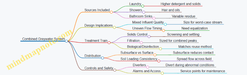
Example: Laundry Plus Shower into One Reuse Path
Assume a household wants to reuse greywater for subsurface irrigation. They include laundry and shower water but exclude bathroom sinks due to shaving residue. The design choices follow the combined logic:
- Equalization tank smooths the timing between showers and laundry.
- Upstream solids control captures hair before filtration.
- Filtration is sized for laundry peaks, since laundry drives solids and detergent load.
- Distribution uses multiple subsurface lines to avoid pulse concentration.
- Fail-safe diversion sends water to an approved non-reuse path if the system can’t treat or distribute it.
This is what “combined” means in practice: one reuse path, but design decisions anchored to the most demanding source and the most likely failure modes.
5.4 Subsurface Distribution Options for Soil Based Reuse
Subsurface distribution means delivering treated greywater into the soil below the surface so the ground can do the final work: filtering, spreading, and supporting biological activity. The core design idea is simple—place water where it can move laterally through soil pores without creating standing pools or surfacing odors.
Foundational Principles for Soil Based Distribution
Start with three constraints: soil absorption capacity, hydraulic loading, and access for maintenance. Soil absorption capacity depends on texture and structure; sandy soils drain quickly, while clay soils can hold water and risk ponding. Hydraulic loading is how much water you apply per day and per square foot of effective area. Access matters because filters and distribution lines still need cleaning, and clogs usually show up where you least want to dig.
A practical rule of thumb is to design for even distribution rather than maximum flow. If one section receives most of the water, that section becomes the “hot spot” for clogging and odors.
Distribution Methods That Work Under the Surface
Trenches and Leach Lines
Trenches are long, shallow excavations filled with graded media or designed piping. Leach lines are similar but typically narrower and deeper. Both spread flow along a length, which helps reduce localized overloading.
Example: A laundry-only system feeding a 30-foot run of distribution line can be laid so each segment receives roughly equal flow. If you instead concentrate the same total length into a short section, you’ll likely see dry spots elsewhere and wet spots near the outlet.
Key design details include pipe perforation pattern, media gradation, and trench geometry. Use a layout that avoids sharp turns and keeps the slope gentle enough to prevent water from racing to one end.
Infiltration Beds
Infiltration beds are larger, flatter zones where water spreads across a broader footprint. They’re useful when you have limited depth but more area, or when you want a buffer against uneven flow.
Example: If your yard has a gentle slope and you can spare a rectangular area, a bed can distribute greywater across multiple internal zones. Even if one zone clogs slightly, the rest can still receive water, reducing the chance of surface wetting.
Beds also help with maintenance planning because you can design access points and keep the distribution zone consistent.
Mound Systems for Limited Soil Depth
A mound system raises the infiltration zone above native soil, using engineered fill to maintain separation from limiting layers. This option is common when the site has shallow bedrock, high water table, or restrictive soil layers.
Example: Suppose you have a yard where the native soil becomes saturated a few feet down. A mound can place the active infiltration area higher, with a controlled fill layer that supports distribution and reduces the risk of water reaching unwanted zones.
Mounds require careful attention to grading, erosion control, and the integrity of the fill. The distribution piping must be protected from settling and designed to distribute evenly across the mound surface.
Choosing Between Options Using Site Logic
Use a simple decision flow: depth first, then area, then soil behavior.
- If you have adequate depth and linear space, trenches or leach lines are often straightforward.
- If you have more area than depth, infiltration beds can provide better distribution.
- If limiting layers are too close to the surface, mounds become the practical path.
Mind Map: Subsurface Distribution Choices
Advanced Details That Prevent Common Failures
Distribution Uniformity
Uniformity depends on how water enters the distribution zone. If the inlet delivers too much to one end, the first section clogs first. Designers often use multiple outlets, controlled flow paths, or internal manifolds so each segment receives a similar share.
Example: A manifold feeding three parallel leach lines can reduce end-loading. If one line clogs, the other two still operate, and the system shows symptoms gradually rather than suddenly.
Separation and Hydraulic Boundaries
Separation distances protect groundwater and reduce the chance that greywater migrates into unwanted zones. Even when soil seems “fine,” a high water table or restrictive layer can change how water moves.
Example: Two yards with the same soil texture can behave differently if one has a seasonal rise in groundwater. The design must respect the limiting layer depth, not just the current dry conditions.
Media and Pipe Considerations
Distribution piping should be protected from solids by upstream filtration, because subsurface lines cannot be backflushed like a kitchen sink. Media gradation affects how water spreads; too fine can clog quickly, too coarse can channel flow.
Example: If your upstream filter is undersized, a trench may look correct on day one but fail after a few months because fine particles migrate into the distribution zone.
Quick Example Layouts
- Laundry-only, adequate depth, linear yard: Use a trench or leach line run with multiple distribution points along the length to reduce end-loading.
- Laundry-only, limited depth, larger flat area: Use an infiltration bed so water spreads across a wider footprint.
- Laundry-only, shallow limiting layer: Use a mound with engineered fill and controlled grading to keep the infiltration zone separated.
Subsurface distribution is ultimately a balancing act between flow, soil, and geometry. When the layout spreads water evenly and respects separation limits, the soil can handle the job without turning your yard into a wet science experiment.
5.5 Surface Application Options and When They Are Appropriate
Surface application means letting treated greywater spread onto the ground surface rather than distributing it through subsurface lines. It can work well when you can control where the water lands, keep it from creating puddles, and match the application rate to how fast the soil can absorb water. The key idea is simple: surface systems are easier to observe, but they require tighter control to avoid nuisance conditions.
Foundational Concepts for Surface Reuse
Start with three practical constraints.
First, surface reuse needs a reliable “landing zone.” That zone should be level or gently sloped, away from walkways, and not directly under downspouts or drip lines that would mix clean and greywater. If the landing zone is too small, water will pool; if it is too large, you may under-apply and waste treated water.
Second, surface reuse must manage solids and surfactants. Even when treatment is solid, laundry water can carry fine particles and detergents that increase surface film and slow infiltration. That’s why surface systems usually pair with stronger solids control than subsurface systems.
Third, surface reuse must avoid direct contact. Many jurisdictions restrict or prohibit spray or runoff to edible plants and require that water not be sprayed onto people or into air. Even where allowed, you should design so the water stays on the ground and does not aerosolize.
Surface Application Methods
Controlled Basin or Swale Application
A basin is a shallow, contained area that receives greywater and allows it to soak in. A swale is a shallow channel that spreads water across a wider area while still keeping it on-site.
Appropriate when:
- You have a small, defined yard area with consistent soil absorption.
- You can build a containment edge so water doesn’t wander.
- You want easy visual checks for pooling or channeling.
Example:
A laundry-only system sends treated water to a 2-foot-deep by 6-foot-wide basin planted with non-edible shrubs. A simple diverter sends flow only when the basin is empty enough to accept it. If you see standing water after an hour, you reduce flow duration or increase the basin area.
Dripline on the Surface with Low-Pressure Delivery
Surface drip uses emitters placed at or just above the soil surface. It is still “surface application” because water emerges at the surface, but it behaves more like subsurface irrigation because it applies slowly and locally.
Appropriate when:
- You want minimal runoff and low wetting of the surrounding area.
- You can keep emitters from clogging by maintaining filtration.
- You can protect lines from foot traffic and lawn equipment.
Example:
Treated greywater flows through a filter and then to a drip zone under mulch. Emitters are spaced so each plant receives water without creating wet rings. If emitters clog, you clean the filter and flush the line, then reduce detergent-heavy loads by using lower-suds cycles when possible.
Surface Spray or Wands
Spray applies water as droplets. This is the most sensitive option because it can create aerosols and drift.
Appropriate when:
- Local rules explicitly allow spray for the intended use.
- You can ensure no overspray onto people, windows, or streets.
- You can maintain consistent pressure and filtration to prevent uneven spray.
Example:
A system uses a nozzle designed for coarse droplets and runs only during times when wind is low. The spray pattern is aimed at a non-edible landscape bed with a physical barrier to stop drift. If you notice misting beyond the bed, you switch to basin or drip.
When Surface Application Is Not Appropriate
Avoid surface application when:
- The site has slow-draining soils that stay wet.
- The area is near foundations, patios, or areas where people walk.
- You cannot prevent runoff during heavy laundry days.
- Treatment quality is inconsistent, especially solids control.
A quick rule of thumb: if you cannot reliably keep the landing zone dry enough between cycles, surface reuse will turn into a maintenance problem.
Mind Map: Surface Application Options and Fit
System Design Details That Make Surface Reuse Work
Surface systems succeed when you treat them like irrigation with guardrails.
Use a simple control strategy: apply in short cycles rather than long continuous runs. Short cycles reduce the chance of pooling and make it easier to match application to absorption. Add a way to stop flow if the landing zone is already wet, such as a timer schedule based on typical laundry use plus an overflow-safe containment design.
Plan for maintenance from day one. Surface drip needs easy access for filter cleaning and line flushing. Basins need periodic inspection for sediment buildup and plant health. Spray systems, if permitted, require frequent checks for nozzle wear and pattern consistency.
Finally, choose plants that tolerate occasional wetting of the root zone. Even when water is treated, it is still greywater, so you want vegetation that can handle intermittent higher moisture without becoming stressed.
Example: Choosing the Right Surface Method
If your yard has a small, contained area and you want maximum visibility, a basin is a good match. If you want the lowest risk of runoff and you can install emitters neatly, surface drip is usually the safer surface choice. If your local rules allow spray and you can control drift, spray can be used, but it demands the most careful setup and monitoring.
The practical takeaway: surface application is not one technique—it’s a set of choices about control, contact, and how quickly your soil can accept water.
6. Designing for Safety with Plumbing Backflow and Controls
6.1 Preventing Cross Connections with Blackwater and Potable Lines
Cross connections are the plumbing equivalent of mixing up the labels on two medicine bottles. One system is meant to be safe to drink; the other is not. A backyard greywater system must never allow greywater to flow into blackwater lines or into potable (drinking) water lines, and it must also avoid the reverse—potable water pushing into greywater piping.
Core Principle
A cross connection happens when two systems share a pathway that can move water in the wrong direction. Direction matters because pressure and flow can change during normal use, power outages, or maintenance. The goal is to create physical separation and reliable backflow prevention so the only possible movement is the intended one.
Where Cross Connections Usually Start
Most problems come from a few predictable design choices:
- Using a shared drain or vent arrangement that accidentally links greywater piping to blackwater.
- Installing a diverter valve without a true air gap or without a listed backflow device.
- Connecting greywater piping to a hose bib, irrigation manifold, or make-up water line without safeguards.
- Relying on “gravity only” when the system can be pressurized by a pump or by surges in the building.
Mind Map: Cross Connection Risk Map
Physical Separation That Actually Works
Start with routing. Greywater piping should be dedicated from the treatment outlet to the distribution point. Avoid tying greywater lines into blackwater drains, even “just upstream” of a trap. If a connection is unavoidable, it must be handled through a code-compliant method that maintains separation and prevents backflow.
Traps and vents are not backflow prevention. A trap blocks sewer gases, not the movement of water under pressure. Similarly, a vent stack does not guarantee that greywater can’t be forced backward if a pressure event occurs.
Backflow Prevention Devices and Their Roles
Backflow prevention is about creating a barrier that stops reverse flow under pressure conditions.
- Air gaps: The simplest concept—keep a vertical separation so water cannot bridge the gap. For example, if treated greywater feeds a tank or distribution header, the outlet should discharge with a visible gap above the receiving surface.
- Atmospheric vacuum breakers: These protect against backsiphonage when there is no continuous pressure. Example: a hose bib style connection used for greywater flushing should not be allowed to draw potable water backward if the pressure drops.
- Reduced pressure zone devices: These protect against both backsiphonage and backpressure. Example: if any potable make-up water is used to maintain a tank level, the make-up line must include a listed reduced pressure zone device so potable pressure cannot push into greywater piping.
Device selection depends on whether the greywater line can be under pressure and whether potable water could be connected. When in doubt, treat it as a pressure risk and choose the more protective option required by local code.
Controls That Prevent “Oops” Moments
A diverter valve is useful, but it must be fail-safe. If power fails, the system should default to a safe state that does not allow greywater to enter blackwater or potable lines.
Example: A laundry-only system uses a diverter to send greywater to treatment during normal operation. During maintenance, the diverter should be locked or positioned so greywater cannot be routed to any drain that could connect to blackwater. If the system uses a pump, include safeguards so the pump cannot pressurize piping that is not intended to be pressurized.
Labeling and Access Control
Labels are not decoration; they reduce the chance of a future “helpful” connection. Clearly mark greywater piping, shutoff valves, and any non-potable outlets. Use physical barriers where possible, such as caps on unused ports and locked access to control panels.
Example: If a yard hose connection exists for flushing filters, it should be clearly marked non-potable and should not be connected to any potable line without a backflow device and an air gap arrangement.
Verification Checklist
Before commissioning, verify separation and backflow protection with a practical checklist:
- Confirm greywater piping is dedicated and does not share fittings with blackwater drains.
- Confirm all potable connections include the required backflow device and are installed per listing instructions.
- Confirm diverter and valve positions are fail-safe and cannot be accidentally switched.
- Confirm there is no hose adapter or temporary coupling that bypasses safeguards.
- Confirm labeling matches the actual system layout.
Example: Safe vs Unsafe Connection
Unsafe approach: A homeowner connects a greywater distribution line to an irrigation manifold that also feeds potable water, relying on a valve to “keep them separate.” If the potable side pressurizes, greywater could be pushed into the potable manifold.
Safe approach: The greywater distribution uses a dedicated manifold and dedicated piping. If make-up water is required, it is added through a reduced pressure zone device, and the greywater outlet maintains an air gap where it discharges into a receiving tank or distribution header.
Summary
Prevent cross connections by combining dedicated piping routes, physical separation, correctly selected backflow prevention, and controls that fail safely. Then verify with inspection and testing so the system behaves correctly not only during normal use, but also during pressure changes and maintenance.
6.2 Backflow Prevention Devices and Where They Are Used
Backflow is when water flows in the wrong direction—typically from a non-potable source back into a potable (drinking) water line. In a greywater system, that risk shows up when pressure changes, power outages, or a clogged line cause the system to “pull” water backward. Backflow prevention devices are the physical safeguards that stop that reverse flow.
Foundational Rule for Device Placement
Treat every connection between greywater plumbing and potable plumbing as a potential cross-connection. Even if you never intend to mix waters, the plumbing can still connect them through shared pressure conditions. The goal is simple: ensure there is no pathway for greywater to reach the drinking-water network.
Where Backflow Risk Appears in Backyard Systems
Backflow risk is not evenly distributed. It concentrates at points where greywater could be forced toward potable lines or where potable pressure could be displaced.
-
At the potable supply connection to a diverter or makeup water line
- Example: Some systems use a small potable “top-up” for freeze protection or to maintain a minimum flow for irrigation. If the greywater side loses pressure, potable water can be pushed into the greywater side unless protected.
-
At any shared piping segment or manifold
- Example: A homeowner routes multiple irrigation feeds through a common valve box. If one feed is greywater and another is potable, a pressure event can move water between them without a direct “mixing” intention.
-
At hose bibs, spigots, and temporary connections
- Example: A garden hose attached to a spigot that is downstream of a greywater valve can become a backflow path if the spigot is not protected.
-
At pumps and pressure zones
- Example: A pump that feeds a distribution line can create negative pressure downstream during shutdown. If the system is connected to potable components, that negative pressure can draw water backward.
Device Types and Their Typical Use Cases
Different devices handle different risk levels. The key is matching the device to the hazard and the plumbing arrangement.
Atmospheric Breaks and Air Gaps
An air gap is the most reliable concept: it physically separates the discharge from the receiving water so reverse flow cannot occur. In practice, you see this as a visible gap between a discharge outlet and a tank or drain.
- Example: A diverter discharges into a tank with a clear air gap above the tank inlet. If the pump stops, greywater cannot siphon into the potable line because there is no continuous water path.
Check Valves
A check valve allows flow in one direction and reduces reverse flow. It is useful, but it is not always sufficient alone because debris, wear, or pressure surges can reduce effectiveness.
- Example: A check valve installed on a pump discharge helps prevent back-siphoning into the pump suction line during power loss.
Reduced Pressure Zone Assemblies
A reduced pressure zone (RPZ) backflow preventer is designed for higher-risk situations where backpressure could occur. It maintains pressure separation using internal relief mechanisms.
- Example: If a potable supply feeds a makeup line for a greywater tank, an RPZ device is often the correct safeguard because the potable side could be forced backward during a pressure event.
Double Check Valves
A double check provides two check valves in series. It is commonly used where the hazard is lower than an RPZ scenario.
- Example: If a system uses potable water only for non-contact functions and the connection is controlled and isolated, a double check may be used depending on local requirements.
Hose Bibb Vacuum Breakers
A vacuum breaker protects against back-siphonage at hose connections. It is typically used where hoses are attached and removed.
- Example: A spigot used for occasional yard watering should have a vacuum breaker so that if the hose is submerged or the line loses pressure, water cannot be drawn back.
Mind Map: Backflow Prevention in Greywater Systems
Integrated Example: Designing a Safe Diverter Setup
Imagine a laundry greywater diverter that routes water either to a treatment tank or to a drain. The system also includes a small potable top-up to keep the tank from freezing in winter.
- The diverter discharge into the tank uses an air gap so the tank inlet cannot siphon water back.
- The potable top-up line includes an RPZ backflow preventer because the greywater tank side can lose pressure during pump cycling.
- A check valve on the pump discharge prevents reverse movement during shutdown, reducing nuisance backflow events.
- Any hose connection in the same valve box uses a vacuum breaker so a submerged hose cannot create a siphon.
This arrangement works because each component addresses a different failure mode: visible separation for siphoning, pressure separation for higher-risk connections, and one-way control for pump-related reversals.
Practical Placement Checklist
- Install devices at every potable connection point, not just the most obvious one.
- Keep protected devices accessible for inspection and testing.
- Avoid relying on a single check valve where the connection could experience backpressure.
- Ensure the plumbing layout does not create hidden shared paths between greywater and potable lines.
Backflow prevention is less about memorizing device names and more about tracing water paths under real pressure conditions. Once you can picture how flow could reverse, the right device placement becomes straightforward.
6.3 Valves Diverters and Automatic Shutoff Strategies
Greywater systems often fail in predictable ways: water goes where it shouldn’t, treatment is bypassed during odd flow conditions, or a stuck valve turns a “mostly reliable” system into a “why is the yard soggy” system. Valves, diverters, and automatic shutoff devices prevent those failures by controlling three things: direction, timing, and safety interlocks.
Core Concepts for Direction Timing and Safety
A diverter decides whether greywater goes to reuse or to a safe discharge path. A shutoff stops flow when reuse conditions are not met, such as when storage is full, treatment is offline, or the receiving area is saturated. Direction control is usually handled by a diverter valve or a set of check valves; timing is handled by sensors, timers, or float logic; safety is handled by backflow prevention, air gaps, and hard interlocks that fail to a safe state.
A useful mental model is a three-step gate:
- Is the water allowed to enter the reuse path?
- Is the reuse path ready to accept it?
- If either answer is no, does the system route the water to a safe alternative without mixing with potable lines or blackwater?
Mind Map: Valve Diverter and Shutoff Roles
Diverter Valve Strategies That Match Real Plumbing
Most backyard systems need one of two diverter behaviors.
A. Divert to Reuse When Conditions Are Good A common setup uses a diverter valve controlled by a controller that reads storage level and treatment status. When the receiving tank is within an acceptable range and the treatment stage is operating, the diverter routes flow to the distribution line.
Example: Laundry-only greywater feeds a small equalization tank. A float switch indicates the tank is not full. When a wash cycle starts, the controller opens the diverter to send treated water to a subsurface distribution manifold. If the tank reaches the high float, the controller closes the diverter and routes incoming flow to a safe drain path.
B. Divert to Safe Discharge When Conditions Are Not Good This is the “don’t gamble” mode. The diverter defaults to safe discharge when power is off, sensors disagree, or treatment is not confirmed. The safe discharge path must be physically separated from reuse distribution and must not create ponding near foundations.
Example: A system uses a pump to move treated greywater to a garden bed. If the pump runs dry or the filter pressure differential indicates clogging, the controller closes the diverter and sends incoming greywater to a permitted drain outlet.
Automatic Shutoff Logic That Prevents Overflows and Misrouting
Shutoff devices should be layered. Relying on a single sensor is like relying on one seatbelt buckle.
1. Level-Based Shutoff Float switches or level sensors prevent overflow in tanks and sumps. Use two thresholds: a “start” level and a “stop” level. That hysteresis prevents rapid cycling.
Example: When the equalization tank reaches the stop float, the controller shuts off the feed pump and closes the diverter to reuse. When the level drops to the start float, reuse resumes.
2. Flow-Based Shutoff A flow switch can detect whether water is actually moving through the reuse path. If the system is commanded to run but flow is absent, the controller shuts down to avoid running pumps against closed valves or clogged filters.
Example: A filter differential pressure sensor is used as a proxy for clogging. If pressure indicates blockage and flow drops below a threshold, the controller stops the reuse pump and diverts incoming greywater to safe discharge.
3. Time-Based Shutoff Timers prevent “stuck on” behavior. If the system should deliver a certain volume during a typical cycle and it doesn’t, the timer stops the pump and forces the diverter to safe discharge.
Example: After a wash cycle ends, the controller expects flow to stop within a set window. If flow continues beyond that window, it assumes a valve is stuck or a sensor is wrong and shuts down.
Fail-Safe Defaults and Manual Override
A well-designed diverter should fail to a safe state on power loss. That usually means valves are spring-return or otherwise configured so that the default routing is away from reuse distribution.
Manual override is not optional for real maintenance. Provide a clearly labeled manual valve that can isolate the diverter or force safe discharge during cleaning. Place service access so a technician can reach the valve without dismantling half the system.
Mind Map: Shutoff Decision Flow

Practical Example: Laundry Cycle with Layered Protection
A laundry-only system uses: (1) a diverter valve to choose reuse vs safe discharge, (2) a high float to stop reuse when the tank is full, (3) a flow switch to confirm the reuse pump is moving water, and (4) a timer to prevent a stuck pump.
During a wash, the controller checks the high float. If the tank is below the stop threshold, it opens the diverter and starts the reuse pump. If the tank rises to the high float, it closes the diverter and stops the pump, routing incoming greywater to safe discharge. If the pump runs but the flow switch does not detect movement within a short window, the controller stops the pump and forces safe discharge. If power is lost, the diverter defaults to safe discharge so the system doesn’t continue feeding reuse blindly.
This layered approach keeps the system predictable: each device handles a different kind of wrong, and together they prevent the common “one sensor lied” failure.
6.4 Odor Control and Venting Considerations for Backyard Systems
Odor problems in greywater systems usually come from two places: gases produced during treatment and gases escaping through plumbing pathways. Venting helps control both by giving air a predictable route and preventing pressure swings that push smells where you do not want them.
Foundational Concepts That Drive Odor
Greywater contains organic matter that can generate hydrogen sulfide and other smelly compounds when conditions are right. Those conditions are typically low oxygen, stagnant water, and warm temperatures. Even if your treatment train is solid, odors can still appear if the system traps air, allows backflow, or vents incorrectly.
A simple way to think about it: your system is a set of connected “pressure zones.” If one zone is sealed while another is not, pressure differences can force gas movement through the path of least resistance—often toward drains, cleanouts, or the yard.
Venting Goals for Backyard Greywater
- Prevent siphon and backpressure in drain lines so traps and fixtures do not get pulled dry.
- Release gases safely so they do not accumulate in tanks or distribution lines.
- Stabilize airflow so pumps and diverters do not create repeated surges that disturb biofilm and solids.
In practice, you want vents that are sized and routed to avoid condensation buildup and to keep vent outlets away from windows, patios, and air intakes.
Vent Routing Principles That Actually Matter
- Keep vent runs short and direct. Long, low-slope vent lines collect condensate, which can become a secondary odor source.
- Avoid venting into enclosed spaces. Garages, sheds, and crawlspaces can trap gases.
- Use proper vent termination height and placement. Terminate where prevailing air will carry odors away from living areas.
- Maintain separation from distribution lines. If a vent line shares a trench with distribution piping, heat and condensation can transfer and worsen odor control.
Tank and Treatment Venting
Most odor issues show up around storage or equalization tanks because they can become the “stagnation zone.” Venting a tank does two things: it prevents pressure buildup and it provides a controlled outlet for gases.
A practical approach is to vent the tank at the highest practical point, then route the vent upward with a slope that discourages condensate pooling. If your design includes a filter chamber or media vessel, consider venting those components as well, because trapped air pockets can promote anaerobic zones.
Distribution Line Venting and Air Management
Distribution piping can create odor pathways if air is trapped and then released in bursts. Those bursts can carry gas bubbles and carryover smells.
To reduce this:
- Design for complete drainage where required. If your system is intermittent, ensure the piping does not hold water in low spots.
- Use air release strategies consistent with local code. Some systems use air relief valves or carefully placed high points; others rely on maintaining flow patterns that prevent air locking.
- Avoid dead ends. Dead-end sections become stagnant reservoirs.
Odor Control Through System Operation
Venting is necessary, but operation determines whether odors are produced.
- Minimize stagnation time. If the system sits idle for long periods, odors are more likely. Use controls that match pump cycles to actual inflow.
- Keep solids moving or removed. Solids settle and create low-oxygen conditions. A well-placed solids removal step reduces both clogging and odor.
- Prevent pump short-cycling. Frequent starts can disturb settled material and increase gas release.
Mind Map: Odor Control and Venting Considerations
Example: Fixing a “Smells Like the Laundry” Complaint
A homeowner notices a sulfur-like odor near a yard cleanout after the washing machine runs. The system has a storage tank and subsurface distribution.
- Observation: The odor appears after the pump stops, suggesting gas release during low-flow or idle conditions.
- Likely cause: The tank vent is routed with a low-slope section that collects condensate, and the vent outlet is positioned too close to a patio.
- Integrated fix: Re-route the vent to keep it mostly upward and reduce condensate pooling, then relocate the termination away from the patio. At the same time, confirm the solids removal step is functioning so the tank does not accumulate settled organics.
Example: Preventing Fixture Trap Loss
If a drain line is vented poorly, pressure changes can pull water out of fixture traps. When that happens, sewer-like odors can appear even if the greywater system itself is clean.
- Observation: Odor is strongest at indoor fixtures, not in the yard.
- Integrated fix: Verify that the greywater diversion does not interfere with the home’s venting system, and ensure any required backflow and diverter controls are installed correctly. Then confirm the greywater piping does not create siphon conditions during pump operation.
6.5 Designing Cleanouts and Access Points for Safe Service
Cleanouts and access points are the “reach-in” parts of your system. They let you remove blockages, inspect components, and verify flow without cutting into finished landscaping or guessing where the problem lives. A good design makes routine service predictable and keeps emergency fixes from turning into plumbing archaeology.
Core Principles for Serviceable Greywater Systems
Start by assuming you will need access at the worst possible time: when the system is wet, the yard is muddy, and you’re trying to fix something before it becomes a bigger mess. That assumption drives three practical rules.
First, place cleanouts where solids and hair are likely to collect. Greywater often carries lint, food particles from sinks, and soap scum that can build up in corners and transitions. If you only provide access at the end of a line, clogs will form upstream and you’ll lose the ability to clear them.
Second, design access so you can remove the blockage without damaging treatment media or disturbing seals. For example, a filter housing should have a service clearance that allows you to open it fully and remove cartridges or backwash media without reaching over sharp edges.
Third, keep access points safe and clearly identifiable. A buried cap that’s flush with soil is easy to miss and hard to open. Marking and locating cleanouts reduces the chance of accidental digging into piping.
Where Cleanouts Belong
Use a simple placement logic: every time the pipe direction changes, the system gets a chance to trap debris. Every time flow slows or expands, solids can settle. Cleanouts should be installed at those “trap points.”
Common locations include:
- At the base of vertical drops where greywater transitions from gravity flow to horizontal piping.
- At changes in direction such as 90-degree elbows, especially if the run is long.
- At the upstream side of filters and diverters so you can isolate and clear the line feeding treatment.
- At the downstream side of treatment components to verify that treated water is moving as intended.
- At the ends of distribution headers where air pockets or sediment can accumulate.
If your design includes a storage tank or equalization chamber, include an access point for inspection and for removing accumulated solids. Even well-filtered greywater can leave behind a thin layer of sludge that needs periodic removal.
Access Point Design Details That Prevent Problems
Access points fail in predictable ways: they’re too small, too hard to reach, or they don’t protect the opening from water and soil intrusion.
Choose a cover size that allows tools and hands to work safely. A cleanout should accept a proper snake or auger if your system uses a line that can clog. If you expect only minor debris, a smaller service port may work, but you still need enough space to remove a plug or cap cleanly.
Provide drainage around access covers so rainwater doesn’t pool over the opening. A simple graded pad or a short gravel apron can keep the cover area drier. Keep the cover seated firmly to prevent soil from migrating into the opening.
Label access points in a way that survives landscaping. A buried marker alone can disappear; pair it with a visible reference point like a stake near a fence line or a painted mark on a nearby structure.
Mind Map: Cleanouts and Access Points
Example: Laundry-Only System with a Filter and Diverter
Imagine a laundry-only greywater line that runs from the washer to a small filter housing, then to a diverter that sends water to either a subsurface line or a garden bed.
- Install a cleanout upstream of the filter near the first elbow after the washer. Lint and soap scum tend to collect there.
- Install a cleanout downstream of the filter right after the filter outlet before the diverter. If flow slows after treatment, you can clear the line without opening the diverter.
- Provide an access cover near the diverter that allows you to inspect the diverter mechanism and confirm valves move freely.
- If the subsurface line includes a header with multiple branches, add a cleanout at the header end so you can flush sediment that settles at the farthest point.
This layout reduces guesswork: when something clogs, you clear the section that feeds the next component rather than dismantling the whole run.
Example: Subsurface Distribution Header with Uneven Coverage
Uneven wetting often comes from partial blockage or air pockets. If you have a subsurface header feeding multiple emitters, include a cleanout at the header end and one near the midpoint if the run is long.
During service, you isolate the header section, open the cleanout, and flush until water runs clear. Then you check whether the blockage was localized to one branch or spread across the header. That distinction matters because it tells you whether the issue is a single emitter line or a broader solids management problem.
Serviceability Checklist for Final Design
Before installation, confirm each access point has:
- A clear reason for being there based on flow path geometry.
- Enough clearance for the tools you’ll actually use.
- A cover that stays stable and doesn’t trap standing water.
- A durable way to locate it after landscaping.
When these are in place, maintenance becomes a controlled task instead of a scavenger hunt with wet gloves.
7. Sizing Components for Reliable Performance
7.1 Estimating Greywater Volumes from Household Use
Estimating greywater volume is mostly arithmetic plus a little realism. You’re trying to predict how much wastewater leaves sinks, showers, and laundry so you can size storage, treatment, and distribution without constant overflow or starvation.
Start with What You Can Measure
Begin with fixture-level usage rather than guessing whole-house averages. If you have water bills only, you can still estimate, but you’ll need assumptions about how much of the bill is greywater versus blackwater.
A practical approach is to build a simple “daily greywater profile” using either:
- Metered fixture counts for a week (showers, loads of laundry, sink use hours)
- Laundry-only assumptions if your system is limited to washing machine discharge
For each greywater source, estimate volume per event, then multiply by events per day.
Convert Fixture Use into Volume per Event
Use these baseline calculations.
Laundry (typical method)
- Find the washing machine’s water factor (gallons per cycle) or estimate from the machine label.
- Multiply by loads per day.
Example: A washer uses 20 gallons per load and runs 4 loads per week.
- Loads per day = 4/7 = 0.57
- Greywater per day = 20 × 0.57 ≈ 11.4 gallons/day
Showers and Baths
- Estimate shower duration and flow rate.
- Volume per shower = flow rate (gpm) × minutes × 1 gallon per 8.33 lb water conversion is unnecessary if you keep units consistent.
Example: 2 showers per day, each 8 minutes, at 2.0 gpm.
- Volume per shower = 2.0 × 8 = 16 gallons
- Daily shower greywater = 2 × 16 = 32 gallons/day
Sinks Sinks are tricky because use is intermittent and variable. A workable method is to estimate “sink minutes per day” and multiply by average flow.
Example: Kitchen sink runs 12 minutes/day at 1.5 gpm.
- Volume = 1.5 × 12 = 18 gallons/day
If you’re reusing kitchen sink water, account for grease and food residue by treating it as higher-risk greywater in your design. If your local rules restrict it, you may exclude it from the greywater total.
Separate Average Daily Volume from Peak Flow
Sizing needs both the average and the “lumpiness.” Greywater systems often fail because peak inflow overwhelms filters or storage, even when the daily total looks fine.
Use a two-number summary:
- Average daily volume: total gallons/day
- Peak inflow rate: gallons/hour during the busiest short period
Example: Laundry runs 4 loads/week. If those loads happen mostly on Saturday, peak inflow can be several times the daily average. If each load takes 45 minutes to discharge, then peak rate during that window is roughly:
- Peak rate ≈ (gallons per load) / (hours per load)
- If 20 gallons per load over 0.75 hours, peak ≈ 27 gph
Apply a Practical Reduction Factor
Not every gallon leaving a fixture becomes usable greywater in your system. Losses come from:
- First-flush diversion if required
- Spillage and hose bib backflow prevention practices
- System downtime during maintenance
A simple design method is to apply a reduction factor to the theoretical greywater volume. For many backyard systems, a conservative starting point is to assume you can use only 70–90% of the calculated greywater volume, depending on how strict your diversion and maintenance schedule are.
Example: If your calculated greywater is 50 gallons/day and you assume 80% usable volume:
- Usable greywater ≈ 50 × 0.80 = 40 gallons/day
Mind Map: Greywater Volume Estimation Workflow
Build a Simple Estimation Table
Use a table to keep assumptions visible.
Example worksheet for one household:
- Showers: 2 showers/day × 16 gallons = 32 gpd
- Laundry: 0.57 loads/day × 20 gallons = 11.4 gpd
- Kitchen sink: 12 minutes/day × 1.5 gpm = 18 gpd
Theoretical greywater total = 32 + 11.4 + 18 = 61.4 gallons/day.
If your system excludes kitchen sink due to local rules, your greywater total becomes 43.4 gallons/day. If you include it but divert the first 5 minutes of each shower, you reduce shower volume accordingly.
Sanity-Check the Numbers
Before you commit to equipment sizes, check whether the result matches lived reality.
- If your estimate is far below what you’d expect from laundry use, you likely undercounted loads.
- If it’s far above, you may have assumed long shower durations or high flow rates.
A quick reality check is to compare your estimated greywater total to typical household water use patterns. If your greywater estimate is larger than total indoor water use, something is off in the assumptions.
Summary Outputs You Need for Design
When you finish this step, you should have:
- Average greywater volume (gallons/day) based on fixture events
- Peak inflow rate (gallons/hour) based on event duration and timing
- Usable greywater fraction after diversion and practical losses
Those three numbers drive the next parts of sizing storage, filters, and distribution so the system behaves predictably instead of improvising.
7.2 Sizing Storage and Equalization for Intermittent Flows
Greywater often arrives in bursts: a laundry cycle might run for an hour, then nothing for several hours. If your treatment and distribution are sized only for the peak moment, you can end up with short-cycling, uneven irrigation, and systems that feel “busy” when they should be steady. Storage and equalization smooth those bursts so downstream components see a more consistent flow.
Core Idea of Equalization
Equalization means you temporarily hold greywater and release it at a controlled rate. Storage provides the volume buffer; equalization provides the timing control. The goal is not to create a giant tank, but to match the release rate to what your treatment and soil distribution can handle without clogging or surface wetting.
A practical rule of thumb: if your system can only accept, say, 10 gallons per minute (gpm) but your laundry dumps 30 gpm for 10 minutes, you need either (1) storage to “spread” that 30 gpm into a longer release window, or (2) a design that limits the incoming flow to the same acceptance rate.
Step 1: Estimate Intermittent Inflow Volume
Start with a realistic event-based volume, not an average-per-day guess. For a typical laundry-only greywater setup, estimate the total greywater per load (wash plus rinse). Then multiply by the expected number of loads per day.
Example: Suppose each laundry load produces 25 gallons of greywater, and you expect 4 loads per day. Total daily greywater is 100 gallons. If loads occur in two clusters—two loads in the morning and two in the evening—your inflow is intermittent even though the daily total is steady.
Step 2: Choose an Equalization Release Rate
Your release rate should align with the limiting component:
- Treatment acceptance rate (filter/media contact time)
- Pump run capability (avoid frequent starts)
- Distribution capacity (soil absorption without runoff)
If your distribution is subsurface, the soil often becomes the limiting factor. A release rate that is too high can create wetting fronts that move laterally and surface pooling that looks like “the system is leaking,” even when it isn’t.
Step 3: Convert Volume into Storage Requirement
Storage sizing is driven by how long you want to spread the inflow.
Let:
- V = volume to buffer (gallons)
- R = desired release rate (gallons per minute)
- T = release duration needed (minutes)
If you want to release V over T minutes, then R = V / T. Rearranging, T = V / R. Storage must cover the time shift between inflow and release.
Example: Using the 25-gallon per load scenario, assume you want to release each load over 60 minutes to keep distribution gentle. Then R = 25 / 60 = 0.42 gpm. If the laundry dumps the 25 gallons over 10 minutes, the storage must hold the difference between inflow and outflow during that 10-minute window.
A simple way to estimate peak storage: during the inflow burst, outflow is still happening at rate R. Storage needed is approximately:
- S ≈ (inflow rate − R) × burst duration
If the burst averages 2.5 gpm for 10 minutes (25 gallons / 10 minutes), then S ≈ (2.5 − 0.42) × 10 = 20.8 gallons. In practice, add headroom for measurement uncertainty and minor delays.
Step 4: Add Operational Buffers
Storage isn’t just a math box. Add buffers for:
- Pump start/stop behavior: you want fewer starts, so you may hold until a minimum level, then run until a lower setpoint.
- Inflow variability: not every load uses the same water volume.
- Maintenance downtime: a filter cleanout might temporarily reduce acceptance.
A common approach is to define three levels:
- Start level: when pumps or valves begin releasing
- Stop level: when release ends
- High alarm level: when inflow exceeds capacity and you need an alert or diversion
Step 5: Validate with a Simple Level-Time Balance
You can sanity-check sizing with a level-time sketch. If the tank level rises during inflow and falls during release, you’re buffering correctly. If it rises steadily even on a “normal” day, your release rate is too low or your storage is too small.
Mind Map: Storage and Equalization Sizing Logic
Integrated Example with Control Levels
Assume again 25 gallons per load. You choose R = 0.42 gpm and plan to release over 60 minutes. The laundry burst averages 2.5 gpm for 10 minutes.
- Estimated storage during burst: ~21 gallons
- Add headroom for level sensor tolerance and a slightly longer burst: say +20% → ~25 gallons
Now set control points:
- Start level corresponds to “enough volume to run” without starving the distribution
- Stop level leaves a small residual volume so the pump doesn’t ingest air
- High alarm triggers if inflow continues faster than release, indicating a clogged filter or unexpected heavy use
This keeps the system calm: the tank fills during the laundry burst, then releases at a steady rate that the soil and treatment can handle.
Common Sizing Mistakes to Avoid
- Sizing storage from daily average only: intermittent peaks still overwhelm distribution.
- Choosing release rate without checking soil acceptance: equalization can still cause runoff if R is too high.
- Ignoring control hysteresis: if start/stop levels are too close, pumps chatter.
- No high alarm or diversion plan: when capacity is exceeded, you need a safe response.
When storage and equalization are sized this way, the system behaves like a steady stream even though the household produces greywater in pulses. That steadiness is what makes safe, efficient reuse practical.
7.3 Sizing Pumps and Determining Head Loss Requirements
A pump’s job is simple: move water from where it is to where it needs to go. The tricky part is that “go” includes friction in pipes, elevation changes, and losses from fittings and treatment components. Sizing correctly means you pick a pump that can deliver the required flow at the total head you calculate—then you avoid underpowered systems that barely trickle or overpowered ones that waste energy and stress components.
Core Concepts for Head and Flow
Start with two numbers: required flow rate (Q) and total dynamic head (TDH). Flow rate comes from your design target, such as gallons per minute to irrigation emitters. Total dynamic head is the energy per unit weight the pump must add to overcome:
- Static lift: elevation gain from tank outlet to highest distribution point.
- Friction loss: resistance as water moves through pipe.
- Component losses: filters, media beds, valves, elbows, tees, and check valves.
A quick sanity check helps: if your system must push water uphill, static lift alone may dominate. If you’re mostly level but have long runs and many fittings, friction and component losses usually dominate.
Step 1: Define Your Flow Path and Measurement Points
Choose a single flow path for sizing, typically the “worst case” path that experiences the most resistance. Mark:
- Pump suction point (tank outlet or filter inlet).
- Pump discharge point.
- Highest and farthest distribution point.
- Every segment of pipe length and diameter.
- Each fitting and treatment component along the path.
Example: You want 20 gpm to a subsurface distribution manifold. The pump sits 2 ft below the tank outlet, the manifold is 8 ft above the tank outlet, and the run includes 120 ft of 1.25 in pipe plus a filter, a check valve, and several elbows.
Step 2: Calculate Static Head
Static head (Hs) is elevation difference between suction and discharge points, plus any required pressure at the discharge. If your discharge point is higher, static head is positive.
Example: Manifold is 8 ft above tank outlet. If you need no extra pressure at the emitters beyond what the design assumes, Hs = 8 ft.
Step 3: Calculate Friction Loss in Pipe
Friction loss depends on pipe diameter, pipe material, and flow rate. Use a consistent method (manufacturer charts, engineering tables, or a calculator) and keep units consistent.
A practical approach for backyard systems:
- Break the run into pipe segments with the same diameter.
- For each segment, compute friction loss per length at your design Q.
- Multiply by segment length.
Example: Suppose 1.25 in pipe at 20 gpm has friction loss of 1.2 ft per 100 ft. For 120 ft, friction loss is 1.2 × 1.2 = 1.44 ft.
If that number feels too small, check your units and flow rate. Friction loss grows quickly with flow, so a small mistake in Q can swing results.
Step 4: Add Fitting and Component Losses
Fittings and components are often handled using either:
- Equivalent length method: treat each fitting as extra pipe length.
- K-factor method: use loss coefficient K with velocity head.
For most DIY-friendly sizing, the equivalent length method is easiest if you have K or equivalent lengths from component data.
Example: If your filter and check valve together are equivalent to 30 ft of 1.25 in pipe at 20 gpm, then additional friction is 1.2 ft per 100 ft × 0.30 = 0.36 ft.
Also include valves and elbows. Even “small” losses add up when you have many fittings.
Step 5: Compute Total Dynamic Head
TDH is the sum of static head and all dynamic losses:
TDH = Hs + Hf(pipe) + Hf(components)
Example: Hs = 8 ft, Hf(pipe) = 1.44 ft, Hf(components) = 0.36 ft. TDH = 9.80 ft.
Step 6: Select Pump Operating Point and Add Margin
Pumps are selected by matching the required flow Q to the pump curve at or near the TDH you calculated. Add a modest margin for real-world differences like slightly higher flow, minor clogging, or temperature effects on water viscosity.
A common rule of thumb is 5–15% margin on TDH, but use your judgment based on how sensitive your irrigation distribution is to pressure changes.
Example: If TDH is 9.8 ft, add 10% margin to get 10.8 ft. Choose a pump whose curve provides 20 gpm at about 10.8 ft of head.
Mind Map: Pump Sizing Workflow
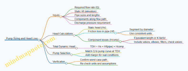
Example: Laundry-Only System with a Filter and Short Run
Assume a laundry-only greywater system sends treated water to a small garden bed.
- Design flow Q: 10 gpm
- Static lift Hs: 5 ft
- Pipe run: 60 ft of 1 in pipe
- Components: cartridge filter, check valve, 4 elbows
If friction loss for 1 in pipe at 10 gpm is 3.0 ft per 100 ft, then pipe friction is 3.0 × 0.60 = 1.8 ft. If the filter plus fittings are equivalent to 15 ft of 1 in pipe at the same flow, component friction is 3.0 × 0.15 = 0.45 ft. TDH = 5 + 1.8 + 0.45 = 7.25 ft.
Add 10% margin: 7.98 ft. Select a pump that can deliver 10 gpm at about 8 ft of head.
Common Mistakes That Break Sizing
- Using the wrong flow rate for the pump curve (for instance, using peak flow when the system runs at a lower steady flow).
- Mixing units between charts and calculations.
- Forgetting the highest point in the distribution path.
- Treating a filter as “negligible” without accounting for pressure drop at design flow.
When you keep the workflow consistent—define the worst-case path, compute static head, compute friction, add component losses, then match the pump curve—you end up with a system that delivers the intended flow without guesswork.
7.4 Sizing Filters and Media Beds for Expected Loading
Sizing a filter or media bed is mostly about matching three things: how much greywater you expect, how dirty it tends to be, and how long the water needs to stay in contact with the treatment surface. If you oversize, you spend more and may create maintenance headaches. If you undersize, you get clogging, bypassing, and performance that drops right when you need it.
Foundational Inputs You Must Know
Start with a simple loading worksheet. For each greywater source, estimate daily flow and peak flow.
- Daily volume (L/day): Use fixture counts and typical run times. A common shortcut is to compute laundry cycles per week and multiply by average cycle discharge.
- Peak flow (L/min): Greywater often arrives in bursts. Peak matters because filters and media beds must handle short surges without flooding or channeling.
- Solids and surfactant load: Laundry greywater usually carries more lint and detergents than rinse water from sinks. You don’t need lab numbers; you do need a realistic “more” or “less” ranking based on your sources.
Then decide your target performance mode. Many backyard systems aim for reliable solids reduction plus stable biological treatment (if used). That choice determines whether you size for hydraulic capacity, solids capture, or both.
Filter Sizing Logic for Solids Capture
For a screen or cartridge filter, the key is how quickly solids accumulate relative to the filter’s available surface area.
A practical sizing approach:
- Choose a filtration goal: For example, “reduce lint and particles that would clog the media bed.”
- Estimate solids loading rate: Use your source ranking. Laundry-only systems typically require more frequent cleaning than sink-only systems.
- Select a filter type and media area: Larger surface area means longer time between cleanings.
- Set a maintenance interval: If you plan to clean weekly, the filter must be able to load that long.
Example: Suppose your laundry produces greywater in two main bursts per day. If you clean the filter every week, you want the filter to hold the expected lint and debris from roughly seven days of bursts. If you notice the pressure drop rising after only two days, you either need more surface area, a finer pre-screen, or better upstream solids removal.
Media Bed Sizing Logic for Hydraulic and Contact Needs
For a media bed, you’re balancing flow-through rate and contact time. Too much flow forces water to move quickly, reducing treatment and increasing the chance of channeling.
Use these two constraints:
- Hydraulic loading: How much water per day per unit area can pass without flooding or excessive head loss.
- Organic and solids loading: How much material the media can handle before it clogs or becomes inefficient.
A reliable method is to size the bed so that, under peak conditions, the bed still has enough effective area to distribute flow. In practice, that means:
- Provide even distribution at the inlet using a diffuser or distribution manifold.
- Avoid short-circuiting by ensuring the bed depth and media volume are adequate.
- Plan for periodic resting or reduced loading if your household uses water in long bursts.
Mind Map: Filter and Media Bed Sizing
Worked Example: Choosing a Reasonable Filter and Bed Size
Assume a household where laundry is the dominant greywater source. You expect two laundry cycles per day, and each cycle discharges roughly 200 L of greywater, giving about 400 L/day. Peak flow might occur during drain events; assume a peak of 5–10 L/min for short periods.
- Upstream filter: Choose a solids removal stage sized so it can be cleaned on your planned schedule. If you intend weekly maintenance, the filter should not reach a “noticeably clogged” state before that. If you see frequent clogging, increase filter surface area or add a pre-screen.
- Media bed: Size the bed so that the daily hydraulic load is spread across the bed area and depth. If your system uses intermittent pumping, ensure the bed can handle the burst without flooding the surface or forcing water through preferential paths.
A simple field check after commissioning is to watch for three signs:
- Pressure drop climbs quickly after cleaning, suggesting insufficient filter capacity.
- Water appears unevenly across the bed surface, suggesting distribution problems or undersized effective area.
- Surface wetting persists after a burst, suggesting hydraulic overload or clogged media.
Common Sizing Mistakes and How to Avoid Them
- Ignoring peak flow: A filter that handles average flow can still fail during bursts.
- Sizing media without distribution: Even a correctly sized bed can underperform if water enters in a narrow jet.
- Treating “laundry” as one uniform stream: Heavy lint loads and high-detergent habits change solids and biofilm behavior.
- Skipping maintenance planning: A design that requires cleaning every other day may be “technically sized” but practically unreliable.
Quick Checklist for Final Sizing
Before you lock in dimensions, confirm:
- Your filter has enough surface area for your chosen cleaning interval.
- Your media bed can handle daily flow without flooding and can tolerate peak bursts without channeling.
- Inlet distribution is designed to spread flow across the bed.
- You have a clear observation plan for pressure drop, wetting patterns, and flow stability.
When these pieces line up, sizing stops being guesswork and becomes a set of testable assumptions you can validate during commissioning and early operation.
7.5 Balancing Flow Rates with Soil Absorption Capacity
A greywater system works only if the soil can accept the incoming water at the same pace. “Balancing flow” means matching three things: how fast water arrives from the house, how fast it can move through treatment and piping, and how fast the receiving soil can infiltrate and spread it without pooling.
Start with Soil Infiltration Basics
Soil absorption capacity is not a single number. It depends on texture, structure, moisture level, and whether the soil surface is sealed by mulch, turf, or compaction. A simple way to think about it is: infiltration is easiest when the soil is dry and loose, and hardest when it is saturated or compacted.
Use a practical rule for design thinking: if you deliver water faster than the soil can infiltrate, the system will push water laterally or upward, increasing the chance of surface wetting, odors, and clogged distribution lines.
Translate Household Use into Peak Flow
Greywater often arrives in bursts. A washing machine might discharge for 20–60 minutes, while a shower or sink may be shorter but more frequent. For sizing, focus on the highest likely discharge rate from your chosen fixtures, not the daily average.
A helpful approach is to estimate peak flow in two steps:
- Estimate the fixture flow rate (gallons per minute) from typical appliance specs or measured observations.
- Estimate how many fixtures can overlap during normal use. Even if overlap is rare, design for the overlap you want to tolerate.
Match Distribution Delivery to Infiltration Rate
Once you know the peak arrival rate, compare it to the soil’s infiltration ability at the distribution depth. Distribution systems spread water across an area, so the effective loading is “flow per square foot” rather than “flow per line.”
If your system uses subsurface distribution, the key is to ensure that each section of pipe receives a manageable share of the total flow. If your system uses a trench or bed, the trench width and length determine how much area is available for infiltration.
Mind Map: Flow Balance Logic
Use Equalization to Smooth the Peaks
If your peak flow is high relative to soil acceptance, equalization is often the cleanest fix. A small tank or surge volume collects greywater during a discharge event, then releases it at a steadier rate.
Example: Suppose your laundry discharges at 3 gpm for 30 minutes, but your soil can only accept the equivalent of 1 gpm over the chosen distribution area without pooling. A 90-gallon equalization volume (3 gpm × 30 minutes = 90 gallons) lets you pump out at about 1 gpm for 90 minutes, giving the soil time to absorb.
The exact numbers depend on your design area and local requirements, but the logic stays consistent: reduce the instantaneous loading even if the total daily volume stays the same.
Control Pumping and Cycling
Pumps can help or hurt. If a pump runs in long bursts, the soil experiences the same peak loading problem as direct discharge. If it cycles too frequently, you may create pressure swings that disturb distribution uniformity.
Aim for steady delivery by:
- Using controls that limit how fast water is released from storage.
- Ensuring the pump curve and piping head loss allow the target flow at operating pressure.
- Designing distribution so that the far end receives water reliably, not just the first section.
Check Distribution Uniformity with a Simple Field Test
Before relying on plants and patience, verify that water spreads as intended. A practical commissioning test is to run clean water or treated greywater through the system while observing wetting patterns.
Example: If you see wet spots only near the start of a subsurface line, the system is likely delivering too much to early sections or the later sections are underfed. The fix is usually geometric or hydraulic: increase distribution area, adjust line layout, or correct flow balancing so each segment gets a fair share.
Avoid the Two Common Failure Modes
- Overloading the soil: surface wetting, persistent dampness, and odors after use. The remedy is to reduce delivered peak (equalization and controls) and/or increase infiltrating area.
- Underfeeding the soil: very slow absorption that leads to frequent backups in the distribution piping. The remedy is to confirm that the system is not clogged or restricted and that the delivered flow matches the intended distribution design.
Advanced Detail: Area-Based Thinking for Trenches and Beds
For trenches, effective infiltrating area includes the trench bottom and sides that contact the receiving soil, adjusted for how water actually spreads. For beds, the distribution pattern matters: a bed with uneven emitter placement can concentrate flow into a smaller zone.
A good design habit is to treat the distribution zone like a “budget.” The soil has a limited spending rate per day and per hour. Your job is to allocate the greywater flow across enough area that the soil’s budget is not exceeded during peak events.
Quick Design Checklist
- Identify peak fixture discharge rate and likely overlap.
- Estimate delivered flow after piping and control losses.
- Ensure distribution area is sufficient for the peak loading.
- Use equalization to smooth bursts when needed.
- Verify uniform wetting during commissioning and adjust if patterns are uneven.
- Recheck after seasonal soil changes, especially if the receiving area compacts or stays wetter than expected.
8. Building the Treatment Train with Practical Component Choices
8.1 Screening and Settling Approaches for Solids Removal
Greywater treatment starts with a simple goal: keep solids from turning your system into a slow, smelly science project. Screening and settling do that job by removing particles before they reach filters, pumps, and distribution lines. Think of them as the system’s “front door,” where the biggest messes get handled first.
What Solids Actually Do to Greywater Systems
Solids in greywater come from lint, food residue, hair, soap scum, and fine grit tracked in from shoes. Even when water looks clear, fine particles can accumulate in media beds and emitters. Larger solids can clog screens and foul pumps. Soap and fats can bind particles into sticky masses, which is why solids removal is not just about visible debris.
A practical design mindset is to separate solids by size and behavior. Screening targets larger, discrete particles. Settling targets heavier particles that can drop out under calm conditions. Together they reduce both clogging risk and maintenance frequency.
Screening Approaches for Larger Particles
Screening uses a physical barrier with openings sized to capture target debris. The most common choices are basket strainers, perforated plates, and mesh screens.
Basket strainers work well for laundry-heavy systems because lint and hair tend to collect in predictable places. Place the strainer where flow is steady enough to avoid bypassing. Use a clear access method so you can remove the basket without dismantling plumbing.
Mesh screens are useful when you need finer control. A finer mesh removes more solids but increases head loss and cleaning frequency. A good rule is to start with a screen that captures the obvious problem solids, then refine only if maintenance logs show persistent carryover.
Perforated plates are durable and can handle grit, but they may require careful cleaning to prevent bridging. If you use plates, ensure the flow direction and cleaning method prevent trapped solids from compacting.
Integrated practice: install a differential pressure gauge across the screen or use a simple visual inspection schedule. When the screen loads up, flow resistance rises and downstream treatment becomes less effective.
Settling Approaches for Heavier Particles
Settling relies on reducing turbulence so gravity can do the work. The two most common approaches are grit removal chambers and sedimentation tanks.
Grit removal chambers are designed for heavier, sand-like particles. They typically use a calm inlet and a controlled outlet so particles drop before water exits. This is especially relevant if the greywater includes laundry water from areas where grit is common.
Sedimentation tanks remove a broader range of settleable solids. They often include a baffled inlet to slow flow and a bottom outlet or cleanout for sludge removal.
Integrated practice: design for easy sludge removal. If you cannot clean the bottom effectively, settling becomes a storage system for solids rather than a removal step.
How to Choose Between Screening and Settling
Use screening first when solids are likely to be large and discrete, such as lint, hair, and occasional debris. Use settling when you expect heavier particles or when you want to reduce the load on downstream filters.
A typical integrated sequence is:
- Screening to catch large debris.
- Settling to capture remaining settleable solids.
- Downstream filtration and disinfection with less clogging stress.
This order matters because settling tanks can be overwhelmed by large solids that would otherwise be removed at the screen.
Mind Map: Solids Removal Logic
Example: Laundry-Heavy System with Lint and Hair
A household routes laundry greywater to a treatment train. After installation, the homeowner notices that downstream filter cartridges clog faster than expected.
Step 1: Add or upgrade screening. Install a basket strainer upstream of the treatment tank. Clean it weekly at first, then adjust based on observed loading. This captures lint and hair before they reach the settling chamber.
Step 2: Add settling for remaining solids. Use a small sedimentation chamber with a baffled inlet. Provide a bottom cleanout so sludge can be removed without digging up piping.
Step 3: Verify with maintenance logs. Record how often the strainer basket fills and how quickly sludge accumulates. If the strainer stays clean but sludge still builds, the issue is likely fine settleable solids that need more effective settling conditions.
Example: Grity Site with Sand Tracked Indoors
A property has sandy soil and frequent foot traffic. Greywater includes laundry water that carries fine grit.
Step 1: Use a grit-focused chamber. A grit removal chamber with a calm inlet helps particles drop out early.
Step 2: Use screening as a safeguard. Even if grit is the main issue, hair and lint still appear. A mesh screen upstream prevents larger debris from interfering with settling.
Step 3: Keep cleaning practical. Schedule cleanouts based on observed sludge thickness rather than guesswork. If sludge is hard to remove, the chamber design needs better access or flow calming.
Practical Design Checks That Prevent Headaches
- Ensure screening and settling components are reachable for cleaning.
- Avoid placing screens where flow is highly variable without bypass protection.
- Provide a clear path for sludge removal so solids do not accumulate unnoticed.
- Monitor loading indirectly through maintenance frequency and flow resistance.
When screening and settling are treated as deliberate, maintainable steps—not optional add-ons—the rest of the treatment train runs smoother and stays cleaner with less effort.
8.2 Media Filtration Options and How to Select Media Types
Greywater treatment often starts with solids control, because solids are the main reason filters clog, pumps struggle, and distribution lines get cranky. Media filtration is the “middle step” between raw greywater and whatever comes next, such as disinfection or subsurface distribution. The trick is matching media type, particle size capture, and flow rate to the actual greywater you’re producing.
Start with What You’re Filtering
Before choosing media, identify the dominant solids source. Laundry greywater usually contains lint, fabric fibers, and detergent residue; bathroom sink greywater tends to include hair and soap scum; kitchen sink greywater can include food particles and grease, which is usually a bad match for simple backyard systems. A practical rule: if you can see or smell heavy contamination, plan for more robust pre-screening before media filtration.
A simple example: if your laundry load includes towels and you run frequent high-spin cycles, expect more lint. In that case, you’ll want a media train that tolerates fiber loading and can be cleaned without heroic effort.
Know the Media “Jobs”
Media filtration typically performs one or more of these jobs:
- Straining captures particles larger than the media openings.
- Depth filtration traps particles within the media structure, which helps with gradual clogging and longer run times.
- Surface filtration captures particles at the media face, which can clog quickly but is easy to understand.
Selection becomes easier when you decide which job matters most. Laundry lint often benefits from depth filtration after a coarse screen. Hair and larger debris often need straining first.
Compare Common Media Options
Sand and Gravel Beds
Sand and gravel are classic depth media. They work well when you can provide steady flow and periodic maintenance. Sand beds can be forgiving, but they require careful sizing and underdrain design to avoid channeling.
Example: A small laundry-only system with intermittent use can still use a sand bed if you include equalization and a pre-screen. Without pre-screening, lint can blanket the surface and reduce performance.
Media Filters with Replaceable Cartridges
Cartridge systems use pleated media or similar elements. They are compact and predictable, but they can clog faster if solids loading is high.
Example: If you have a modest household and you’re filtering mostly bathroom sink greywater, a cartridge filter can be a clean, manageable choice. If you’re filtering frequent towel loads, you’ll likely replace cartridges often unless you add strong pre-screening.
Foam and Synthetic Depth Media
Foam and other synthetic media can capture fine particles and are often easier to handle than sand. They can be good for systems that need a balance between capture and maintenance simplicity.
Example: A system that struggles with uneven flow can benefit from foam media because it can distribute capture through its thickness rather than only at the surface.
Media with Backwash Capability
Some media filters are designed for backwashing, which can restore flow without full replacement. Backwash systems require water for cleaning and careful control to avoid sending dirty backwash to the wrong place.
Example: If you have a reliable way to route backwash to an approved disposal point, a backwash-capable filter can reduce ongoing labor.
Select Media Using a Simple Decision Logic
Use this sequence to avoid guessing:
- Remove large debris first with screening or settling.
- Choose capture strategy based on particle type: straining for hair and chunks, depth for fine solids.
- Match media to flow pattern: intermittent flows need equalization or media that tolerates cycling.
- Plan maintenance: decide whether you will clean, backwash, or replace.
- Set a target particle size consistent with your next step. If you’re aiming for subsurface distribution, you generally want to prevent fine solids from migrating into soil lines.
Mind Map: Media Selection Framework
Practical Examples That Tie It Together
Example: Laundry-Heavy Household
- Pre-treatment: lint screen plus settling or equalization.
- Media choice: depth media (sand bed or synthetic depth) after coarse removal.
- Maintenance plan: periodic cleaning based on observed flow reduction.
Reasoning: lint is small enough to slip past coarse screens but large enough to clog surface filters quickly. Depth media spreads capture through thickness, buying time between cleanings.
Example: Bathroom Sink Reuse with Low Solids
- Pre-treatment: simple strainer.
- Media choice: cartridge or fine depth media.
- Maintenance plan: replace cartridges on schedule or when flow drops.
Reasoning: the solids load is usually lower and more consistent, so a cartridge filter can stay in its comfort zone.
How to Judge Media Performance Without Fancy Instruments
You don’t need a lab to make good decisions. Track three observable indicators:
- Flow rate at the outlet: steady flow suggests the media is not blinding.
- Pressure drop across the filter if you have gauges: rising pressure indicates clogging.
- Effluent clarity: if it suddenly worsens, the media is likely overloaded or channeling.
When these indicators change together, treat it as a maintenance trigger rather than a mystery. Media filtration is a system of cause and effect, not a black box.
8.3 Disinfection Options and How to Match Them to Use Cases
Greywater disinfection is the step that reduces microbes before water contacts soil, plants, or surfaces. The key design idea is simple: pick a disinfection method that fits your water quality, your contact time, and your allowed operational complexity. If you treat dirty water like it’s clean, you’ll spend your effort fighting the wrong problem.
Foundational Concepts That Drive the Choice
Start with three inputs: (1) what microbes you’re trying to control, (2) how much organic matter is present, and (3) how long the water can stay in contact with the disinfectant.
- Organic load and solids consume disinfectant and shield microbes. That’s why filtration and solids control belong upstream of disinfection.
- Contact time matters because many disinfection processes work by exposure, not by instant “magic.” If your system has short residence time, you need a method that performs well under those conditions.
- Byproduct and handling constraints matter because backyard systems must be safe for people, pets, and maintenance.
A practical rule: if your system often runs with cloudy water or frequent filter bypass, prioritize robust solids removal first, then choose a disinfection method that tolerates the remaining variability.
Disinfection Options and What They’re Good At
Ultraviolet Light
UV disinfection uses light to damage microbial DNA. It’s popular for residential systems because it doesn’t add chemicals to the water.
- Best fit: relatively clear greywater after filtration, with predictable flow.
- Design implications: UV performance depends on water clarity and lamp intensity. Use a pre-filter and include a way to monitor lamp status and flow.
- Operational reality: if the water is frequently turbid, UV output drops and you’ll need tighter upstream filtration.
Example: A laundry-only system with a cartridge filter and a small equalization tank feeds UV. The tank smooths flow, and the filter keeps turbidity low, so UV can be sized for consistent exposure.
Chlorination
Chlorination uses chlorine or hypochlorite to inactivate microbes. It can be effective even when water quality varies, but it requires careful dosing and control.
- Best fit: systems that can maintain a measurable residual and have controlled dosing.
- Design implications: you need dosing equipment, mixing, and a contact chamber sized for the required exposure.
- Operational reality: too little chlorine means poor disinfection; too much can create odor and may affect plants depending on concentration.
Example: A system that receives occasional higher-soil laundry loads uses a dosing pump tied to flow rate and a contact tank. A simple residual check ensures the system isn’t “under-dosing” during high-demand periods.
Ozonation
Ozone is a strong oxidant that can disinfect effectively and breaks down quickly, reducing long-term residual concerns.
- Best fit: where you can support an ozone generator and manage power and maintenance.
- Design implications: ozone systems require good pretreatment and controlled contact conditions.
- Operational reality: equipment complexity is higher than UV, and you must ensure the water has enough contact time for consistent results.
Example: A larger backyard system with a dedicated treatment skid uses ozone after filtration and a contact chamber sized for the expected flow range.
Hydrogen Peroxide and Advanced Oxidation Variants
Hydrogen peroxide-based approaches can disinfect and oxidize organics, but they still depend on dose, contact time, and water quality.
- Best fit: when you want chemical disinfection without chlorine and can manage dosing and contact.
- Design implications: you need dosing control and a reliable contact volume.
- Operational reality: peroxide can be less forgiving if solids and organics are high, because oxidant demand rises.
Example: A system with moderate turbidity uses peroxide dosing after a media filter and a contact tank. Maintenance focuses on keeping the filter effective so oxidant demand stays predictable.
Matching Disinfection to Use Cases
Use cases differ mainly by where the water goes and how sensitive the pathway is.
- Subsurface distribution to soil: disinfection aims to reduce microbial risk before soil contact. Filtration and consistent exposure are especially important because soil can be forgiving, but sloppy pretreatment isn’t.
- Surface application to mulch or landscape: disinfection must handle higher exposure risk and potential contact with people and pets. You’ll typically want stronger pretreatment and a method with reliable performance under variable conditions.
- Laundry-only systems: water is often more consistent than mixed greywater, making UV a strong candidate when filtration is solid.
- Mixed greywater systems: variability is higher, so chemical methods with controllable dosing or systems designed for robust pretreatment are often easier to keep consistent.
Mind Map: Disinfection Selection Logic
A Systematic Selection Checklist
- Confirm pretreatment performance: verify solids removal is stable across typical laundry cycles.
- Estimate contact time realistically: use actual flow patterns, not idealized averages.
- Choose a method you can monitor: UV needs lamp and flow checks; chlorine needs dosing control and residual verification.
- Plan for maintenance: filters, lamps, and dosing components must be serviceable without turning the system into a weekend project.
- Validate with simple operational checks: turbidity trends, residual readings where applicable, and odor observations help catch problems early.
Example: If your system’s filter pressure drop swings widely, treat that as a disinfection design constraint. Fix filtration first, then size UV or chemical contact based on the stabilized water quality.
8.4 Managing Sludge and Spent Media Disposal Practices
Greywater treatment is mostly about moving unwanted stuff from “in your system” to “somewhere it can be handled safely.” Sludge and spent media are the two big categories you’ll manage. Sludge is the concentrated solids that settle out or collect in filters. Spent media is the material in media filters or biofiltration units that has trapped organics and can no longer clean effectively.
Core Concepts That Drive Disposal Decisions
Start with two practical questions: what is in it, and how much of it you have.
First, solids from greywater typically include lint, food residues from laundry, soap precipitates, and biological growth. The exact mix depends on detergents, water temperature, and whether you used a pre-filter. Second, “how much” depends on your loading rate and how often you clean. A system that filters well but is cleaned late will produce heavier sludge batches.
Disposal choices usually follow a simple logic: keep it contained, keep it labeled, and match the handling method to local rules and the system type. Even if your system is small, treat sludge like a waste stream with a defined path, not like something you can casually rinse away.
Mind Map: Sludge and Spent Media Disposal Flow
Sludge Handling from Removal to Containment
Sludge removal is easiest when you design for it. If your tank has a cleanout port, use it rather than improvising with tools that gouge surfaces. When you open a cleanout, expect a mix of water and solids. Letting it drain into a small, dedicated container reduces mess and makes the waste easier to transport.
Containment matters more than people think. Use a lidded, leak-proof container or a heavy-duty bag inside a rigid bin. Label it “Greywater Treatment Sludge” and include the date of removal. This prevents mix-ups with yard waste and helps you keep a consistent maintenance record.
Example: Settled Solids from a Small Equalization Tank
Imagine a laundry-only system with a settling chamber. After a few weeks, you notice the filter upstream clogs faster. You open the chamber cleanout and find a wet layer of solids. You scoop solids into a sealed container, allow the remaining liquid to drain back into the chamber or into a small catch container, and then close everything promptly. The next day, you record the approximate volume removed and the odor level. If odor is strong, you schedule the next cleanout sooner.
Spent Media Disposal Without Guesswork
Spent media is usually disposed when performance drops: pressure rises across the filter, flow slows, or water quality indicators worsen. Don’t wait for a complete failure. Media that is overloaded can release trapped organics when disturbed, which increases odor and makes cleanup harder.
Treat spent media as a wet solid. If your media is in a cartridge, remove it carefully and keep it upright to avoid spills. If it’s in a media bed, scoop or lift it in sections so you don’t create a muddy slurry. Place it into a sealed container immediately.
Example: Cartridge Media from a Laundry Filter
A homeowner uses a cartridge filter after a diverter. Every month, the pressure gauge indicates higher resistance than usual. Instead of stretching the interval, they replace the cartridge on schedule. The used cartridge goes into a sealed bag inside a rigid bin. They wipe the housing with a damp cloth, then discard the cloth as part of the waste stream. This keeps the work area clean and reduces the chance of residue getting into soil.
Dealing with Odor, Liquids, and Cleanup
Odor is often a sign that solids have been sitting too long or that the system is receiving high-strength inputs. Shorten the time between removal and containment closure. If liquids drain from sludge, capture them in the same waste container rather than letting them run across the yard.
Cleanup should be controlled. Use absorbent pads or shop towels for small drips, then bag them with the waste. Avoid hosing down the area; it spreads residue and can create unintended runoff.
Tracking Volumes to Prevent “Surprise” Disposal Batches
A simple log prevents unpleasant surprises. Record: date of removal, approximate volume (for example, “one 5-gallon bucket” or “half a bag”), system run time since last service, and any changes in detergent or household habits. Over time, you’ll see whether sludge volume is stable or trending upward.
Example: Maintenance Log That Explains a Sudden Increase
After switching to a different laundry detergent, a household notices sludge volume increases and filter clogs happen sooner. The log shows the cleanout interval stayed the same, but the removed solids grew from “about one bucket” to “two buckets.” That pattern suggests more precipitates or faster biological accumulation, so they adjust cleaning frequency and ensure the pre-screen is functioning properly.
Practical Disposal Checklist
- Remove sludge or media using designed access points.
- Contain immediately in leak-proof, lidded containers or sealed bags inside rigid bins.
- Label with removal date and system identifier.
- Capture draining liquids; do not allow runoff.
- Bag absorbents used for cleanup with the waste.
- Record approximate volume and any odor or performance changes.
- Dispose through the method required by local rules for the waste type.
8.5 Integrating Components into a Simple Maintainable Layout
A maintainable greywater system is one you can understand at a glance, service without guesswork, and troubleshoot without dismantling half the yard. The goal is not to cram everything together; it’s to arrange components so flow direction, access, and maintenance tasks are obvious.
Start with a Clear Flow Path
Begin by writing the system’s “story” in one sentence: source fixtures send greywater to pretreatment, then treatment, then distribution. Next, translate that story into physical order.
A practical layout rule is to keep components in the same sequence as the water moves. For example, if you use a diverter valve, filter, pump, and then a subsurface distribution line, place them so a person can follow the piping from inlet to outlet without crossing paths. This reduces installation errors and makes later inspections faster.
Use Serviceable Access as a Design Requirement
Maintenance fails when access is an afterthought. Plan for three kinds of access:
- Inspection access for checking flow, levels, and alarms.
- Removal access for taking out filters, media, or pump parts.
- Cleaning access for flushing lines and clearing solids.
Concrete example: if your filter sits inside a buried vault, include a riser and a removable lid sized for safe removal of the filter cartridge or basket. If you can’t remove the component without standing in a puddle of greywater, you’ll eventually skip maintenance. That’s not a moral failing; it’s physics.
Keep Controls Close to What They Control
Controls should live near the components they manage, but not so close that routine service requires electrical disassembly. A common approach is:
- Put the diverter valve and its manual override near the first junction.
- Place the pump control panel near the pump, with a clear label for power, alarm, and service mode.
- Route sensor wiring so it doesn’t run through areas where you’ll dig or remove media.
Example: if you use a float switch in a small equalization tank, mount the switch so it can be inspected without draining the tank. Then wire it to a control box that has a visible status light for “pump running” and “high level.” When something goes wrong, you’ll know whether the issue is water level, power, or flow restriction.
Design for Solids Management Without Making It Complicated
Solids are the reason many systems slow down. Integrate solids handling by separating “where solids drop out” from “where solids must not go.”
A maintainable pattern is:
- Pretreatment captures lint, hair, and larger particles.
- Treatment handles finer contamination.
- Distribution stays as clean as possible.
Example: if you include a settling chamber before a pump, keep the chamber’s outlet above the expected sludge layer. Add a cleanout or drain at the low point so you can remove settled material without opening the entire line.
Make Flow Direction Obvious with Labels and Color Coding
Even careful installers forget details later. Use labels that match the physical layout.
- Label pipes by function: “Greywater In,” “Treated Outlet,” “Backwash Drain,” “Overflow.”
- Label valves by action: “Diverter to Treatment,” “Service Isolation,” “Drain.”
- Use consistent color coding on valve handles if your local practice allows it.
Example: a diverter valve labeled “Laundry Only to Treatment” prevents the classic mistake of routing greywater to the wrong branch during maintenance. The label costs little; the avoided confusion saves hours.
Build a Simple Layout Template
Use a repeatable “box” concept: each component sits in a defined zone with clear boundaries.
Example Layout with Reasoning
Imagine a laundry-only system with pretreatment, a small pump, and subsurface distribution.
- Zone 1: Inlet and Pretreatment sits closest to the laundry outlet. Include a filter and a settling section with a drain.
- Zone 2: Equalization and Pumping sits next. Keep the pump and float switch accessible from above.
- Zone 3: Treatment Finishing comes after pretreatment if you use media or disinfection. Place it so media changes don’t require moving the pump.
- Zone 4: Distribution is last, with manifolds and cleanouts at logical junctions.
This arrangement reduces cross-zone interference. When you service the filter, you don’t disturb distribution lines. When you service the pump, you don’t open the media chamber. The system stays understandable even when you haven’t looked at it in months.
Final Checks That Keep It Maintainable
Before you finalize the layout, verify these items:
- Every component has a clear “remove path.”
- Every line has a “clean path” via cleanouts or drains.
- Controls can be tested without bypassing safety functions.
- Labels match the actual piping order.
If you can draw the layout as a simple left-to-right flow diagram and point to where maintenance happens, you’re already ahead of most real-world problems.
9. Designing Distribution for Gardens and Landscapes
9.1 Selecting Reuse Targets Including Trees Shrubs and Lawns
Choosing reuse targets is where your design becomes practical. The goal is to match the greywater’s typical quality and flow pattern to what the landscape can safely absorb, without creating wet spots, odors, or clogged soil.
Start with Two Ground Rules
First, decide whether your system is meant for subsurface irrigation or surface application. Subsurface targets (trees, shrubs, and many soil-based beds) usually tolerate greywater better because water is delivered below the surface where contact with people and pets is limited.
Second, treat laundry greywater as the “baseline” stream for most designs. It often has more detergents and suspended solids than bathroom sink water, so if your plan works for laundry, it usually works for lighter streams.
Match Targets to How Water Moves Through Soil
Plants don’t just “drink.” They also influence how water spreads. Trees and shrubs create long-term pathways through roots and soil structure, which can help infiltration stay consistent. Lawns, by contrast, often sit on shallow, compacted topsoil and can show surface wetting quickly if distribution is uneven.
A simple way to think about it: trees and shrubs are forgiving about where the water lands, while lawns are less forgiving about repeated overwatering in the same spots.
Trees as Reuse Targets
Trees are strong candidates for subsurface greywater because their root zones are deeper and their watering needs are spread over a larger volume of soil.
Example: If you’re reusing greywater for a single ornamental tree, place distribution lines in a ring around the trunk, not directly under it. Keep emitters or perforations several inches away from the trunk so the root collar stays dry. If your system is intermittent, the tree’s deeper roots help absorb pulses without turning the surface into a swamp.
Design check: Ensure the tree’s expected mature root spread fits your distribution footprint. If the tree grows wider than your irrigation zone, the system may under-water the outer roots and over-water the inner area.
Shrubs as Reuse Targets
Shrubs work well when you can define a bed boundary and maintain consistent spacing. Their root zones are typically shallower than trees, but they still benefit from subsurface delivery.
Example: For a hedge row, use a continuous trench or manifold line running behind the planting line. Space distribution points so each shrub receives water without overlapping too heavily. Overlap isn’t always bad, but heavy overlap can create localized saturation that encourages algae at the surface and clogging in the distribution media.
Design check: Choose shrub locations that avoid low spots where water naturally collects. Greywater systems should manage water intentionally, not rely on the yard’s “surprise drainage.”
Lawns as Reuse Targets
Lawns can be reused, but they require careful distribution uniformity and control of surface wetting. If your system delivers water unevenly, lawns will show it as dry patches and muddy patches.
Example: If you’re irrigating a small lawn area, use a layout that creates overlapping coverage patterns that are consistent across the whole zone. Run the system long enough to wet the intended depth, but not so long that water ponds. A practical approach is to start with shorter cycles and observe soil moisture after a few runs.
Design check: Avoid placing greywater irrigation where runoff will flow toward sidewalks, driveways, or foundations. Even if the water is “clean enough” for plants, it can still cause nuisance issues when it migrates.
Combine Targets Without Creating Conflicts
Real yards mix trees, shrubs, and lawn. The key is to prevent one target from stealing water from another.
Example: If you have both a lawn and a shrub bed, consider separate distribution zones. That way, you can run the lawn only when distribution is uniform and run the shrub zone when you want deeper, steadier absorption. Mixing them into one zone often forces compromises that show up as uneven growth.
Use a Simple Selection Matrix
Pick targets based on three factors: delivery method, soil infiltration, and exposure risk.
| Target | Best Delivery Method | Why It Works | Common Failure Mode |
|---|---|---|---|
| Trees | Subsurface | Deeper absorption volume | Over-concentrating near trunk |
| Shrubs | Subsurface | Bed-defined root zones | Local saturation in overlaps |
| Lawns | Subsurface or carefully controlled surface | Even coverage supports uniform growth | Dry/muddy patches from uneven distribution |
Mind Map: Reuse Targets Selection
Final Practical Rule
If you can’t confidently control distribution uniformity, start with trees and shrubs. Lawns are the “precision instrument” of reuse targets, while trees and shrubs are the “steady team players.”
9.2 Subsurface Irrigation Layouts for Even Coverage
Even coverage starts with a simple truth: subsurface irrigation distributes water through soil, not through pipes. Your layout should therefore manage three things at once—flow rate, wetting pattern, and how the soil absorbs water along the path.
Foundational Layout Ideas
Begin by choosing a distribution style that matches how water will spread underground.
- Line-based distribution uses one or more long trenches or drip lines. It works well when you want a steady wetting band across a bed.
- Zone-based distribution splits the yard into sections so each section receives water at a controlled rate.
- Emitter-based distribution relies on many small outlets (emitters) spaced along a line, letting soil absorb water locally.
A practical rule: if you can walk the yard and describe where the plants are, you can describe where the water should go. Then you can translate that description into lines, zones, and emitter spacing.
Mind Map: Subsurface Coverage Planning
Step 1: Match Emitter Spacing to Soil Behavior
Emitter spacing controls how often water enters the soil. If emitters are too far apart, soil between them stays dry; if they’re too close, you risk overlapping wetting zones that push water upward.
Use this workflow:
- Estimate infiltration from how quickly the soil absorbs water during a controlled test (for example, run clean water through a temporary hose at a similar rate and observe how far it spreads).
- Choose emitter spacing so wetting zones overlap slightly but not heavily. Overlap is what creates even coverage; too much overlap creates surface wetting.
- Keep emitter flow consistent by using the same emitter type and maintaining pressure within the manufacturer’s range.
Example: If your soil absorbs slowly and you notice water tends to stay near the trench, you can reduce line spacing or increase run time in shorter pulses rather than placing emitters extremely close.
Step 2: Set Line Spacing and Layout Geometry
Line spacing determines how wide the wetted area becomes. For even coverage, lines should be arranged so their wetted bands cover the target area without leaving gaps.
Common geometries:
- Parallel lines for rectangular beds. Place lines so the distance between them is roughly aligned with the expected wetted width from each line.
- Grid patterns for larger lawns or mixed plantings. Multiple lines form a grid where each line contributes to neighboring coverage.
- Perimeter plus interior lines for irregular shapes. Perimeter lines handle edges that often dry faster due to wind and heat, while interior lines fill the middle.
Example: In a narrow side yard, parallel lines along the length often outperform a single line in the center because the soil near the boundary can dry sooner.
Step 3: Choose Depth to Control Wetting Depth
Depth affects both coverage and safety. Deeper placement can reduce surface wetting, but it can also place water beyond the effective root zone.
A good approach is to place emitters so the wetted bulb reaches the main root zone for your plants. For many landscape plantings, that means keeping the wetting zone within the top portion of the soil profile where roots actually work.
Example: If you irrigate shrubs with shallow roots, placing emitters too deep can create a situation where the soil stays wet but roots don’t reach it, leading to dry-looking plants.
Step 4: Balance Flow Across Multiple Lines
When you split flow into several lines, the first line often receives more if you don’t balance hydraulics. Even coverage depends on distributing flow so each line gets a similar share.
Use these practical methods:
- Use zone valves so each zone runs independently at a controlled flow.
- Use pressure regulation so emitters see consistent pressure.
- Keep branch lengths similar within a zone to reduce uneven pressure loss.
Example: If one branch line is 30% longer than another, it may under-deliver water. Either shorten the branch, add a balancing approach, or run shorter cycles per zone.
Step 5: Verify Coverage and Adjust Without Guessing
After installation, verification should be simple and measurable.
- Run the system long enough to create a visible subsurface wetting response, but not long enough to cause pooling.
- Check for dry pockets by probing soil moisture at several points between lines.
- Check for overlap problems by looking for surface dampness near the trench line.
If you find dry pockets, increase overlap by reducing line spacing or emitter spacing. If you find surface wetting, reduce overlap by increasing spacing or lowering run time and cycling.
Mind Map: Layout Verification Loop
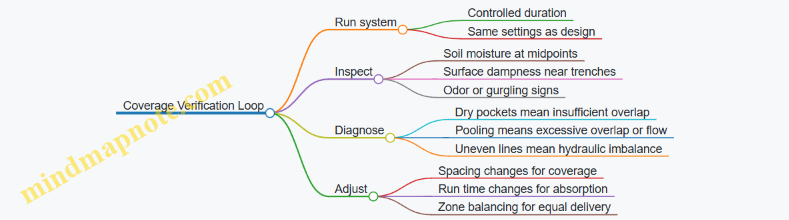
Quick Example Layout for a Typical Backyard Bed
Imagine a 20 ft by 30 ft planting area with shrubs and a small lawn edge. A workable plan is:
- Create two zones: one for the lawn edge and one for the deeper bed.
- In each zone, run parallel subsurface drip lines across the 20 ft width.
- Place emitters along each line at a spacing chosen to match your soil’s absorption behavior.
- Set emitter depth to keep the wetted zone within the shrub root zone.
After the first run, probe between lines. If the midpoint soil is drier than the trench area, reduce line spacing or adjust emitter spacing. If the surface shows dampness, reduce run time and avoid pushing more water than the soil can absorb at once.
9.3 Emitter Spacing and Distribution Uniformity Basics
Emitter spacing decides how much of your yard gets water and how evenly it gets it. Distribution uniformity decides whether plants thrive or quietly suffer from alternating wet and dry zones. The goal is simple: match the irrigation pattern to the soil’s ability to absorb water without creating puddles or dry patches.
Foundational Concepts That Control Spacing
Start with three linked ideas: emitter discharge, wetted area, and soil absorption.
- Emitter discharge is the flow rate leaving each emitter (often listed as gallons per hour or liters per hour). Higher discharge can wet more area, but it also increases the risk of runoff if the soil can’t absorb it fast enough.
- Wetted area is the footprint where water spreads in the soil. It depends on emitter rate, pressure, soil texture, and how long water runs.
- Soil absorption is how quickly water infiltrates. Sandy soils absorb quickly but may not hold water well. Clay soils absorb slowly and can create surface wetting if you apply too fast.
A practical rule: spacing is not chosen to “cover the surface.” It’s chosen to create overlapping wetted zones that meet plant needs without exceeding infiltration capacity.
How to Think About Uniformity
Uniformity improves when every part of the irrigated area receives roughly the same amount of water over the same time. Two common causes of unevenness are:
- Hydraulic variation: pressure drops along the line, so downstream emitters flow less.
- Coverage gaps: spacing is too wide, so wetted areas don’t overlap.
Uniformity is easiest to manage by controlling both. Use pressure regulation and proper layout, then verify spacing matches the expected wetted radius.
Choosing Emitter Spacing Using Wetted Radius
Most designs begin with an assumed wetted radius for your emitter and soil. You then set spacing so adjacent wetted areas overlap enough to avoid dry seams.
- If you assume a wetted radius of R, a common starting point is spacing around 1.5R to 2R for many subsurface setups, because overlap helps compensate for small variations.
- For surface or near-surface emitters, you often need tighter spacing because water can spread unevenly due to evaporation and surface microtopography.
Example: Suppose your emitter is expected to wet about 0.6 m (2 ft) radius in your soil. If you space emitters at 0.9–1.2 m (3–4 ft), you’ll likely get overlap rather than isolated “islands” of wet soil.
Accounting for Pressure and Flow Consistency
Even perfect spacing can fail if flow varies too much.
- Pressure regulation keeps emitter output stable. Without it, the first emitters may deliver far more than the last.
- Line sizing reduces head loss. Undersized pipe increases pressure drop, which reduces downstream discharge.
A simple check: after installation, run the system and observe whether the far end behaves like the near end. If you can measure flow at accessible emitters, compare them; if you can’t, watch for consistent wetting patterns across the zone.
Laying Out Emitters for Real Yards
Uniformity depends on geometry. A straight run of emitters behaves differently than a corner, a slope, or a bed with irregular edges.
- Corners and edges often need extra attention because water distribution patterns can change where lines turn.
- Slopes can cause uneven infiltration. Water may move downslope in the soil, leaving the upslope side drier.
- Beds with mixed plant types should still use uniform irrigation within the bed, then adjust plant needs with separate zones rather than relying on “hope and spacing.”
Mind Map: Emitter Spacing and Uniformity
Example: Two Spacing Choices on the Same Soil
Assume the same emitter and soil, but two different spacings.
- Case A: Wide spacing. Emitters are spaced so wetted areas barely touch. You’ll often see a repeating pattern: slightly wet bands where overlap occurs and drier strips between them. Plants in the dry strips may look fine at first, then show stress after a few irrigation cycles.
- Case B: Overlapping spacing. Emitters are closer, creating consistent overlap. The soil stays more evenly moist, and the system tolerates small variations in pressure and run time.
If you’re forced to choose, overlapping spacing usually improves uniformity more reliably than trying to “stretch” coverage with wider spacing.
Quick Checklist Before You Finalize Spacing
- Do you have a reasonable wetted radius assumption for your soil and emitter type?
- Is the spacing set to create overlap, not just contact?
- Are you using pressure regulation and properly sized lines to reduce downstream flow drop?
- Have you considered edges, corners, and slope so the pattern doesn’t break?
- Can you verify uniformity by observing wetting patterns after commissioning?
9.4 Avoiding Overwatering and Protecting Plant Health
Overwatering is the most common “looks like it’s working” failure mode in backyard greywater reuse. Plants may look greener for a week or two, but roots can’t breathe when the soil stays saturated, and that’s when problems start: yellowing leaves, slow growth, and fungal issues. The goal is simple—deliver greywater in amounts the soil can absorb quickly enough, then let the ground cycle back toward normal moisture.
Start with Soil Absorption, Not Garden Wish Lists
Plants don’t drink on a schedule; soil controls the pace. Before you adjust irrigation, check how water behaves in your yard. Run a normal hose cycle and observe infiltration: does water soak in within an hour, or does it linger? If it lingers, your distribution design must slow down or move to a subsurface approach that places water deeper and more gently.
A practical rule: if you can see standing water or feel spongy ground after a watering event, you’re applying more than the soil can take. Greywater systems should be designed to avoid that condition even during peak laundry days.
Use a Simple Water Budget
Treat greywater as a partial replacement for irrigation, not an unlimited supply. Build a basic water budget using three inputs: (1) expected greywater volume from your household, (2) the irrigated area you plan to serve, and (3) seasonal plant water needs. Then cap the greywater contribution so the total applied water stays within what the soil can handle.
Example: Suppose your laundry produces enough greywater to cover a small garden bed. If that bed is also receiving regular sprinkler irrigation, you may be doubling the water without realizing it. The fix is not “more treatment,” it’s coordination: either reduce sprinkler runtime or route greywater to a separate zone.
Match Application Method to Soil and Plant Type
Subsurface distribution usually reduces surface wetting and helps prevent root-zone oxygen loss. Surface application can work for certain landscapes, but it requires careful control of flow rate and timing.
- Subsurface irrigation: Place water where it can infiltrate without pooling. Keep emitters or distribution lines below the zone where roots are most sensitive to saturation.
- Surface application: Use low, slow delivery so water soaks in rather than runs off. Avoid applying when the ground is already wet from recent rain.
Plant type matters too. Lawns and thirsty shrubs tolerate more frequent moisture, while many trees and drought-tolerant ornamentals prefer deeper, less frequent watering. If you reuse greywater on mixed plantings, design for the most sensitive group.
Control Frequency and Flow Rate
Overwatering often comes from applying too often, too fast, or both. Greywater sources can be intermittent, so your system should avoid dumping a large slug of water into the soil.
Practical approach:
- Equalize flow using storage or buffering so the distribution sees steadier, smaller doses.
- Limit discharge rate so the soil can absorb it. If your distribution is pressurized, use pressure and emitter sizing that match infiltration.
- Time irrigation to avoid saturated conditions. Skip greywater application after heavy rain or when the soil is already dark and cool several inches down.
Watch for Root-Zone Saturation Symptoms
Plants give clues before you measure anything. Look for patterns rather than single leaf issues.
- Yellowing leaves with soft, slow growth can indicate persistent saturation.
- Mushroomy soil smell or visible algae on nearby surfaces suggests water is staying put.
- Wilting during the day that doesn’t improve at night can happen when roots can’t access oxygen.
If symptoms appear, reduce application frequency first, then reduce total volume. Changing treatment components won’t fix a soil oxygen problem.
Use Soil Checks as Your Reality Filter
A quick, repeatable check beats guesswork. Probe the soil 6–12 inches (or to your root depth target) after a greywater event. You’re aiming for moisture that is present but not waterlogged.
Example: After a laundry-heavy day, check the soil the next morning. If it feels wet and cool throughout the probe depth, you applied too much or too quickly. If it’s damp near the surface but drier deeper down, your system is closer to the balance you want.
Mind Map: Overwatering Control Logic
Example: Fixing a Wet Spot in a Shrub Zone
A homeowner notices a consistently damp patch near a subsurface line. The shrubs look slightly droopy and leaves are pale.
- Confirm soil condition by probing around the damp patch. The soil stays wet at the shrub root depth.
- Reduce frequency by limiting greywater distribution to fewer laundry cycles per week.
- Reduce total volume by shrinking the served area or adding a diversion so excess greywater bypasses the zone.
- Re-check after two cycles. The damp patch should shrink, and leaf color should stabilize.
This sequence works because it addresses the real constraint: the soil’s ability to absorb and exchange oxygen.
Practical Checklist Before You Run Greywater
- The ground is not already wet from recent rain.
- Distribution avoids pooling and surface runoff.
- The served area matches your available greywater volume.
- You can probe the root zone and find damp, not waterlogged, soil.
- Plant symptoms are improving after you reduce application.
When you treat greywater as a controlled input—measured by soil response rather than household convenience—overwatering becomes a solvable design and operation problem, not a mystery.
9.5 Managing Runoff and Ensuring Water Stays Where It Should
Greywater reuse works only when the water goes to the intended place and exits the system safely. “Stays where it should” means two things: (1) the treated water infiltrates into the target soil zone instead of running off the surface, and (2) any excess water is routed away from foundations, sidewalks, and saturated zones that can cause odors or plant stress.
Core Idea: Control the Water Balance
Start with a simple water balance for the reuse zone: inflow from greywater, infiltration into soil, and outflow as drainage or evaporation. If inflow repeatedly exceeds infiltration capacity, you get surface wetting, pooling, and bypassing of treatment benefits. If infiltration is too low, the system backs up and pushes water where it shouldn’t.
A practical rule: design for the worst realistic day, not the average week. Laundry cycles are lumpy, and a “small” extra load can tip the balance.
Site Reading Before Design Tweaks
Runoff behavior is mostly determined by slope, soil texture, and the presence of impermeable layers.
- Slope: Even a gentle grade can move water laterally. If the reuse area slopes toward a structure, you must add containment or change the layout.
- Soil texture: Sandy soils infiltrate quickly but can spread water deeper than intended. Clay soils infiltrate slowly and are prone to surface wetting.
- Layering: A perched water table or compacted layer can create a hidden “bathtub” that forces water sideways.
A quick field check helps: after a normal rain, observe where water stands and how long it takes to dry. If the area stays wet for days, you’re not just dealing with “slow infiltration”; you’re dealing with a drainage constraint.
Build Containment So Runoff Has Nowhere to Go
Containment is not about trapping water forever; it’s about preventing lateral escape.
- Place distribution upslope of sensitive areas. Keep the reuse zone away from foundations, property lines, and paved surfaces.
- Use a berm or swale when the yard grade would otherwise carry water away. A berm should be sized to handle the maximum expected runoff from the reuse zone during a short period.
- Maintain a buffer zone around the distribution area. This reduces the chance that a clogged section sends water sideways.
Example: If your laundry greywater line feeds a subsurface trench near a driveway, a shallow berm along the driveway edge can stop lateral movement during high-flow laundry loads.
Match Distribution Depth and Layout to Soil Behavior
Subsurface distribution reduces surface runoff, but only if the trench or bed is placed at the right depth and has enough lateral spread.
- For slow soils: increase the wetted area (more emitters or longer trenches) so the same volume spreads out and infiltrates without surcharging.
- For fast soils: avoid placing distribution too deep. Keep the active infiltration zone within the soil volume that can support treatment and plant uptake.
A common mistake is “more depth” as a fix. Depth can move water beyond the intended treatment zone, especially in sandy or fractured soils.
Prevent Surcharging with Storage and Controls
Even well-designed systems can receive bursts of water. Surcharging happens when the distribution can’t accept the inflow rate.
- Equalization storage smooths peaks. A small buffer tank or timed dosing can turn a 30-minute laundry surge into a steadier release.
- Dosing control prevents continuous flow. Timers and level controls help ensure the system pauses when the distribution zone is saturated.
- Overflow routing: if your storage tank or distribution chamber has an emergency outlet, route it to a safe drainage path that does not contact people or edible crops.
Example: A pump-fed subsurface bed with a simple level switch can stop dosing when the tank level drops, reducing the chance of pushing water into surface wetting zones.
Manage Surface Expression and Runoff Pathways
If any water reaches the surface, treat it as a signal to adjust.
- Keep the reuse area vegetated. Bare soil erodes and channels runoff.
- Avoid direct discharge to slopes. If the distribution is near a slope, use a containment berm and ensure the distribution is not aligned with the natural flow direction.
- Grade the surrounding yard so stormwater and greywater don’t mix in unpredictable ways.
A helpful check: after a laundry-heavy day, walk the yard 30–60 minutes later and again the next morning. Look for damp bands, rills, or edges that stay wet. Those patterns point to clogged sections, insufficient wetted area, or a lateral flow path.
Mind Map: Managing Runoff and Keeping Water Where It Should
Quick Integrated Example: From Problem to Fix
Suppose your subsurface trench is near a slight slope and you notice a damp strip running downhill after laundry days.
- Confirm the pattern: the strip aligns with the slope, suggesting lateral movement.
- Check infiltration: if the trench area stays wet longer than the rest of the yard, infiltration capacity is limited.
- Apply containment: add a berm upslope of the trench to block lateral escape.
- Adjust distribution: widen the wetted area by extending the trench length or adding a parallel line.
- Add dosing control: use timed or level-based dosing to reduce peak inflow.
This sequence fixes the cause (excess lateral flow and limited infiltration) rather than just covering up the symptom (wet grass).
10. Installation Workflow from Materials to Commissioning
10.1 Preparing the Site and Protecting Existing Utilities
A greywater system is only as good as the ground it sits on and the plumbing it doesn’t accidentally disturb. Site preparation is where you prevent the most common headaches: leaks, clogged lines from construction debris, and damage to existing utilities that were never meant to be “in the way.”
Site Walkthrough and Layout Verification
Start with a walk-through that matches your design drawings to reality. Confirm where the greywater sources discharge, where treatment components will sit, and where distribution lines will run. Measure again the distances that matter for hydraulics and maintenance access, not the ones that look convenient.
A practical habit: mark the planned trench centerline and tank footprint with temporary flags or spray paint, then check clearances to fences, trees, and structures. If you find a conflict, adjust the route now rather than after excavation.
Utility Protection and Excavation Safety
Before digging, identify all underground utilities. Use local utility locate services where required, and verify markings on the ground. Treat every marked line as real until proven otherwise.
When you excavate, use hand digging near utility marks and keep mechanical digging farther away. Maintain a safe working area and protect exposed lines from impact and abrasion. If you must cross a utility, follow your design’s crossing method and keep the crossing depth and separation consistent.
Mind Map: Site Preparation Priorities
Ground Conditions and Trench Planning
Soil behavior drives performance. If the soil is rocky, expect more difficult trenching and consider how you’ll bed and support pipe. If the soil is heavy clay, plan for careful bedding and avoid creating channels that move water unpredictably.
Set trench slopes according to your design and keep them consistent. Uneven slopes cause low points where debris collects and high points that trap air. For distribution lines, ensure the trench bottom is smooth and firm; do not place pipe on loose fill.
A simple check: after you shape the trench, run a straight board or string line along it to spot dips and humps before laying pipe.
Preventing Debris and Construction Contamination
Construction debris is the silent enemy of filters and media beds. Cap pipe ends immediately after cutting, and keep fittings covered when work pauses. Don’t let soil wash into open lines during rain.
Before connecting components, inspect pipe interiors for grit. If you see sediment, clean it out before assembly. During commissioning, flush lines to remove remaining debris; a short, controlled flush beats a long-term clog.
Protecting Existing Plumbing and Avoiding Cross Connections
Your greywater system must not interfere with potable water or blackwater plumbing. Confirm that any diverter valves, backflow prevention devices, and connection points are installed exactly where intended.
Use clear labeling on any valve that changes flow direction. If a valve is accessible, label it so a future maintenance visit doesn’t turn into a guessing game. Also verify that drain lines from greywater sources are not mistakenly tied into blackwater lines.
A helpful workflow: dry-fit the piping, confirm the routing and valve orientation, then install with final torque and correct gasket placement. Take photos before closing trenches so you can later verify what’s hidden.
Base Preparation for Tanks, Filters, and Pumps
Treatment components need stable support. Prepare a level, load-bearing base so tanks don’t settle and pumps don’t misalign. Remove topsoil and organic material from under the equipment pad.
If you’re using a concrete pad, ensure it’s sized for the equipment footprint and includes space for maintenance access. If you’re using a gravel base, compact it properly and keep it level. Uneven support can create stress points in plumbing connections.
Drainage Control During Construction
Construction sites collect water. Plan for it so trenches don’t fill and float. Keep excavations from becoming ponds, and manage runoff so it doesn’t carry sediment into open pipe runs.
If you encounter unexpected groundwater, stop and reassess. Waterlogged trenches can shift pipe alignment and create voids under bedding.
Documentation and Verification Before Closing
Before backfilling, verify key items: pipe alignment, slope, bedding contact, and that all cleanouts are accessible. Record trench depths and any deviations from the plan.
Take a few targeted photos: each major connection, the trench before cover, and the equipment base. This turns future troubleshooting from “where is it?” into “we already know.”
Example: Utility Conflict Resolution Without Chaos
You planned a trench route that crosses a marked utility line. After hand-digging near the mark, you discover the utility is deeper than expected and closer to the trench centerline. Instead of forcing the pipe to fit, you adjust the trench route by shifting the run laterally and re-checking distances to the treatment unit. You then re-confirm slope and bedding continuity before laying pipe. The system stays compliant with the design intent, and the utility remains undamaged.
10.2 Installing Piping Trenches and Maintaining Proper Slopes
A greywater system lives or dies by two things you can see: the pipe path and the slope. If the route is sensible and the grade is consistent, flow stays predictable and maintenance stays boring—in the best way.
Trench Planning Before You Dig
Start by confirming the route on the ground, not just on paper. Mark the pipe centerline, then check three constraints along the entire run: (1) distance to the treatment unit, (2) separation from potable water lines, and (3) where you can physically keep a continuous slope without creating dips.
Lay out cleanouts and inspection points early. A trench that hides every joint is a trench that will eventually demand excavation. Place access where you expect clogs to form: near changes in direction, near filters, and at the start of distribution.
Excavation and Bed Preparation
Excavate to a depth that leaves room for bedding and cover. Bedding matters because it prevents the pipe from “bridging” over uneven soil. Use a uniform, compactable bedding material (commonly sand or fine gravel, depending on local practice) and compact it in lifts.
Keep the trench bottom smooth and continuous. If you have to remove soft spots, replace them with the same bedding material and compact again. A single low spot can create a pocket where solids settle, turning a minor issue into a recurring one.
Maintaining Proper Slopes
For gravity sections, slope is the difference between steady flow and intermittent pooling. The goal is to move water fast enough to carry fine solids along, while not forcing excessive velocities that can stress joints.
Measure slope continuously, not just at the ends. Use a laser level or string line with a level reference, and check at regular intervals (for example every 5 ft / 1.5 m). Record the measured grade so you can compare it to the design.
If you encounter a conflict mid-run—like a rock or an unexpected utility—do not “fix” it by flattening the slope. Instead, adjust the trench depth upstream or downstream so the pipe returns to the intended grade.
Slope Checklist You Can Actually Use
- Confirm the pipe material and diameter match the design before setting grade.
- Verify slope direction so the pipe always trends toward the receiving component.
- Keep joints aligned while bedding is still adjustable.
- Avoid bellied sections caused by over-excavation or under-compaction.
- Re-check slope after the pipe is laid and before backfill.
Pipe Laying and Joint Integrity
Dry-fit the pipe sections first. Ensure each joint seats fully and that gaskets are clean and correctly oriented. Misaligned joints can create internal ledges where solids accumulate.
Support the pipe on the bedding so it does not float. If you must cross a utility trench, follow local separation rules and provide additional support as required.
For any section that transitions from gravity to pressure, confirm the elevation at the changeover point. A small elevation error can cause air trapping or uneven flow.
Backfilling Without Creating Problems
Backfill in stages. First, place bedding material around and above the pipe to stabilize it. Compact carefully to avoid shifting the pipe off grade.
Do not dump large rocks directly against the pipe. Use controlled fill and keep the pipe protected until the trench is fully backfilled to the required cover.
If your system includes subsurface distribution, keep the distribution zone consistent. Uneven backfill density can change how water spreads through the soil, which shows up later as dry spots or soggy patches.
Example Installation Scenario
A laundry-only system runs from a treatment unit to a subsurface distribution line. The design calls for a continuous gravity slope.
- The installer marks the route and identifies two low areas where the trench would naturally flatten.
- Instead of digging shallower at the low points, they deepen the trench upstream so the pipe maintains grade.
- They compact bedding in short sections, lay the pipe, and re-check slope every few pipe lengths.
- After joint seating is confirmed, they backfill in lifts, keeping the pipe centered and protected.
The result is a line that drains predictably after each cycle, with fewer opportunities for solids to settle.
Mind Map: Trench Installation and Slope Control
Quick Field Verification Before You Move On
Before closing the trench, run a final visual and measurement check: confirm the pipe follows the marked line, verify slope at multiple points, and ensure no section has sagged. If something looks off now, it will look worse after backfill—because gravity is very consistent about consequences.
10.3 Setting Up Tanks Filters Pumps and Controls Safely
A safe greywater system is mostly about controlling three things: where water goes, what happens when it stops, and how you prevent unwanted mixing. Tanks, filters, pumps, and controls are the tools that make those three things predictable.
Foundational Safety Checks Before You Install
Start with the basics: confirm your piping routes, verify backflow prevention requirements, and ensure every component has a clear service path. A practical rule: if you can’t reach a part to clean it, you can’t maintain it, and if you can’t maintain it, it will eventually fail in the least convenient way.
Use a simple “no surprises” checklist:
- Label every line at both ends before connecting.
- Keep greywater piping physically separated from potable lines.
- Install shutoff valves so you can isolate the system without draining the whole yard.
- Plan for overflow handling so a stuck valve doesn’t create surface pooling.
Tanks Setup for Stable Flow and Controlled Storage
Tanks do two jobs: they buffer intermittent household discharge and they give solids a place to settle before filters work. Place the tank where you can access the lid, inspect the inlet, and remove sludge.
Inlet design matters. If you connect a noisy inlet directly to the tank bottom, you can resuspend settled solids. A common fix is to use an inlet diffuser or a short drop pipe that directs flow below the water surface.
Add an outlet configuration that avoids drawing from the tank bottom. A floating intake or a dip tube set above the sludge layer helps keep filters from becoming a solids magnet.
Overflow and venting are safety features, not accessories. Provide an overflow outlet sized for the worst-case inflow and route it to a safe disposal path approved for your setup. Venting prevents pressure buildup that can push water into unintended areas.
Filters Setup for Reliable Treatment
Filters protect downstream components and help keep distribution lines from clogging. Treat filters as maintenance-heavy parts: they should be easy to remove, clean, and reinstall.
Choose a filter type that matches your solids load. For laundry-heavy greywater, a screen or cartridge filter often handles larger debris, while a media filter can polish finer particles. Regardless of type, install it with:
- A clear flow direction arrow.
- Isolation valves on both sides so you can service it without shutting down the entire system.
- A pressure gauge or simple differential indicator if your design allows it, so you can tell when cleaning is needed.
If you use a backwash-capable filter, ensure the backwash line has a safe discharge route. Backwash water is still greywater; it must not end up where it can create cross-contamination.
Pumps Setup for Correct Operation Under Real Conditions
Pumps move water, but they also respond to conditions like air, head pressure, and intermittent demand. Before you connect power, confirm the pump curve matches your system’s required flow at the expected head.
Install the pump so it can’t run dry. If your tank level can drop below the pump intake, use a float switch or level sensor to stop the pump. For extra safety, add a high-level cutoff to prevent overflow when controls fail.
Check suction conditions. Cavitation and air entrainment often come from poor intake submergence or vortexing. Keep the intake submerged and avoid placing it too close to the tank wall where swirling flow can pull air.
Use unions or removable couplings on pump connections. This is one of those “future you will thank present you” details that prevents cutting pipe during maintenance.
Controls Setup for Safe Switching and Fail-Safe Behavior
Controls should make the system behave correctly when things go wrong: power interruptions, clogged filters, or unexpected inflow.
A typical control strategy includes:
- Level-based pump start and stop.
- A filter clog indicator that triggers an alarm or stops pumping.
- A diverter or valve control that prevents greywater from entering distribution when treatment is bypassed or unavailable.
Wire controls with clear segregation from potable plumbing. Use proper enclosures and strain relief so vibration and moisture don’t loosen connections.
Test controls in a controlled sequence. First, verify sensor readings by simulating tank levels. Next, confirm valve actuation direction and pump start/stop behavior. Finally, run a short cycle and observe for leaks, abnormal noise, and correct discharge.
Mind Map: Tanks Filters Pumps and Controls Safely
Example: Laundry-Heavy System with Tank, Screen, Pump, and Diverter
A common setup starts with a tank that receives laundry greywater, then a screen filter before pumping to subsurface distribution.
- Tank inlet uses a diffuser so incoming water doesn’t churn sludge.
- Tank outlet uses a dip tube set above the settled layer.
- A screen filter sits downstream with isolation valves and a differential pressure gauge.
- The pump starts only when the tank level reaches the start float and stops at a lower float.
- A high-level float triggers a shutoff to prevent overflow.
- A diverter valve prevents pumping if the filter is clogged beyond the set threshold.
During commissioning, you run a short cycle, confirm the pump stops at the lower level, verify the diverter stays in the correct position, and check that no leaks appear at unions or filter housings.
Example: Preventing Cross-Contamination During Filter Service
If you need to clean a filter, you isolate it with the two shutoff valves, then stop the pump using the control logic. This prevents greywater from bypassing the filter through unintended paths. After cleaning, you reopen valves in the correct order and run a brief test cycle to confirm flow direction and stable operation.
10.4 Pressure Testing, Flushing, and Leak Checks Before Use
Before a greywater system sees real flow, you want three things to be true: water can move where it should, air and debris are out of the lines, and every connection is tight. Pressure testing, flushing, and leak checks are the sequence that turns “looks installed” into “is ready.”
Foundational Concepts You Need First
Pressure testing verifies that pipes, fittings, and joints can hold a specified pressure without loss. Flushing clears construction sediment, metal shavings, and biofilm starters that can clog filters or distribution emitters. Leak checks confirm that seals behave under real conditions, not just under a static test.
A practical mindset helps: treat each step as a filter for different failure modes. Pressure testing catches gross joint failures. Flushing catches loose debris and trapped air. Leak checks catch slow seepage that might not show up during a short test.
Step 1: Pressure Testing with Clear Pass Criteria
- Isolate the section being tested. Close valves so you test only the intended pipe run and components. If your system includes a tank or media vessel, keep it out of the pressure test unless the manufacturer explicitly allows it.
- Use the correct pressure and duration. Follow your local code or the equipment instructions. If you don’t have a target, use the system designer’s specified test pressure and hold time.
- Watch for pressure drop and visible seepage. A small drop can indicate a leak or temperature change. If the temperature is stable, a drop is a red flag.
- Inspect joints while the system is pressurized. Wipe suspect fittings dry, then look for fresh moisture. Even a thin film can become a drip once flow starts.
Example: If you pressurize a 20-meter run and the gauge falls steadily over 15 minutes, don’t assume it’s “just settling.” Re-check every glued joint and threaded connection in the tested segment.
Step 2: Flushing to Remove Construction Debris
Flushing is not “turn it on and hope.” It’s controlled movement of water through the system so debris exits before it reaches filters and emitters.
- Flush from the source side toward the distribution side. This pushes sediment out in the direction it would travel during operation.
- Use clean water and capture runoff safely. Direct discharge to a drain, approved area, or temporary containment so you don’t create a muddy mess.
- Flush until discharge runs clear. “Clear” means no visible particles, not just fewer bubbles.
- Include the components that trap debris. If you have a filter housing, flush through it only if the design allows; otherwise flush upstream first, then install the filter and flush again as required.
Example: After installing a new filter manifold, the first flush may carry sand-like grit. If you stop early, that grit can lodge in the smallest passages and cause uneven watering later.
Step 3: Leak Checks Under Realistic Conditions
Pressure tests are static; leak checks are dynamic. After flushing, you want to confirm the system behaves during low and normal flow.
- Start with low flow. Open the diverter or control valve gradually. Low flow reduces the chance of dislodging debris you missed.
- Check connections at multiple points. Focus on joints that are hard to access later: unions, threaded fittings, tank penetrations, and any pump discharge connections.
- Verify drainage behavior. If your design includes overflow or relief paths, confirm they carry water away without backing up.
- Confirm filter housings and media areas stay dry where they should. A wet exterior can mean a seal leak even if the system “seems to work.”
Example: A fitting may pass a pressure test but seep during pump start because vibration changes the seal contact. That’s why you check after the pump runs.
Mind Map: Pressure Testing, Flushing, and Leak Checks
Mini Checklist You Can Use on Site
- Pressure test completed with stable gauge and no fresh moisture.
- Flushing completed until discharge is visibly clear.
- Filter and distribution components installed as required.
- System started at low flow, then stepped up to normal.
- All accessible joints inspected again after pump start.
- Any overflow or relief discharge verified to run freely.
Integrated Example Sequence for a Typical Laundry-Only Run
You test the laundry greywater branch line first, isolating the tank and distribution laterals. After passing, you flush the branch line until discharge runs clear. Then you install or confirm the filter stage, connect the distribution piping, and run low flow. Finally, you step up to normal operation while inspecting every union and tank penetration for seepage. If anything looks damp, you fix it before the system is considered ready—because “almost dry” tends to become “wet enough to cause problems.”
10.5 Commissioning Procedures Including First Run Verification
Commissioning is the moment your design becomes a working system. The goal is simple: confirm that water flows where it should, gets treated as intended, and never crosses into places it shouldn’t. Do it in a sequence that reduces rework—start with isolation and safety checks, then move to flow verification, then confirm treatment and distribution behavior.
Step 1: Pre-Start Safety and Readiness Checks
Before any water runs, verify the system is physically ready.
- Confirm separation from blackwater and potable lines. Trace every inlet and outlet. If a valve diverter exists, ensure it is installed in the correct orientation and labeled.
- Check electrical safety. Pumps and controls should have correct grounding, dry electrical connections, and strain relief on cords or wiring. If a control panel exists, ensure covers are in place.
- Verify venting and drainage paths. Filters and tanks need air to move water smoothly. Make sure vents are not capped and that any drain lines discharge to an approved location.
- Inspect installed components. Confirm filter housings are seated, gaskets are intact, media is installed correctly (no bypass gaps), and unions are tightened.
Example: If your filter housing has an arrow for flow direction, don’t assume it’s obvious once everything is buried. Mark the direction with tape before closing trenches.
Step 2: System Isolation and Controlled First Fill
Your first run should be controlled enough that you can stop quickly.
- Set valves to a safe initial position. Typically, divert flow to the intended treatment path and keep distribution valves closed until you confirm upstream performance.
- Prime pumps if required. Many pump issues during first run are just trapped air. Follow the pump’s priming method and confirm the suction line is fully connected.
- Fill tanks and check for leaks. Start with low flow. Watch joints, fittings, and tank seams. Fix leaks before increasing flow.
Example: If you see a slow drip at a union, tighten it once, then re-check. Over-tightening can deform gaskets and create a leak that wasn’t there before.
Step 3: First Run Verification for Flow and Controls
Now you confirm that the system moves water as designed.
- Verify diverter operation. If the system uses a diverter valve, run a small amount of greywater and confirm the valve switches at the expected trigger.
- Check pressure and flow indicators. If you installed a pressure gauge or flow meter, record readings at steady operation. Compare them to your design expectations.
- Confirm no bypassing. Observe whether water exits only through the intended outlets. A common mistake is a misrouted hose or a misconnected drain.
Example: During first run, you might notice the distribution line stays dry while the tank level rises. That can indicate a closed irrigation valve, a stuck check valve, or insufficient pump priming.
Step 4: Treatment Performance Checks
Treatment isn’t just “installed”; it must behave correctly under real flow.
- Filter behavior. Confirm water passes through the filter without channeling. If you have a clear housing, watch for consistent flow distribution.
- Media contact and head loss. Ensure the system doesn’t stall as it loads. If pressure rises quickly, you may have incorrect media placement or an undersized pre-filter.
- Disinfection verification when applicable. Confirm the unit is powered, interlocks are satisfied, and the flow rate is within the required operating range.
Example: If a media bed is installed upside down, water may find the path of least resistance. The first run will show uneven flow and rapid clogging.
Step 5: Distribution Verification for Coverage and Runoff Control
Finally, confirm that treated water reaches the landscape safely and predictably.
- Check subsurface or surface outlets. For subsurface distribution, verify that emitters or perforations are not blocked and that water spreads evenly.
- Look for surface wetting. If you see pooling or persistent damp spots, adjust depth, spacing, or flow rate. Surface wetting is often a sign of distribution mismatch.
- Confirm shutoff behavior. When the source stops, the system should settle without backflow or draining in the wrong direction.
Example: If one zone stays dry, check for a clogged emitter, a closed zone valve, or an air pocket. Air pockets are especially common after trench work.
Step 6: Commissioning Documentation and Handover
Record what you observed so future maintenance is faster and less guessy.
- Create a commissioning log. Include date, system ID, component list, initial settings, measured flow/pressure, and any adjustments made.
- List baseline maintenance actions. Note filter cleaning interval starting point and any media inspection schedule.
- Provide a simple “what to watch” checklist. Include signs like recurring odors, repeated filter pressure spikes, or uneven wetting.
Use a date such as 2026-02-15 in your commissioning log if you need a reference entry.
Mind Map: First Run Verification Workflow
Example: A Practical First Run Sequence
- Set diverter to treatment path; keep distribution valves closed.
- Prime pump; fill tank slowly; confirm no leaks.
- Run a short test load; confirm diverter switches and flow meter/pressure gauge stabilize.
- Open one distribution zone at a time; verify even wetting or subsurface spread.
- Stop the source; confirm system settles without draining backward.
- Record readings and any valve adjustments; clean filters if pressure rises quickly.
This sequence prevents the most common commissioning headaches: fixing leaks after burial, discovering a reversed flow direction after media is loaded, and chasing distribution problems that are actually control or priming issues.
11. Operation and Maintenance for Long Term Reliability
11.1 Daily Weekly And Seasonal Maintenance Tasks
Greywater systems work best when maintenance is boring and consistent. The goal is to keep solids from building up, keep flow paths open, and confirm that safety controls still do their job. Use a simple routine: check, clean, verify, and record.
Daily Maintenance Tasks
Daily checks take 2–5 minutes and focus on symptoms that show up fast.
- Listen and watch for flow stability. After laundry cycles, confirm that the system drains without gurgling, slow surges, or repeated pauses. A steady sound usually means the filter and distribution path are not choking.
- Check for odors near access points. A mild “wet soil” smell can be normal, but sharp sewage-like odors suggest a cross-connection, stagnant water, or a diverter stuck in the wrong position.
- Inspect visible components. Look for leaks at fittings, damp spots around tanks, and wetness around cleanouts. If a leak is small today, it becomes a bigger excavation tomorrow.
- Confirm diverter position when used. If your system includes a diverter or valve that routes flow, verify it returns to the intended state after use. Many failures are mechanical and simple: a valve not fully seating.
Example: After a load of laundry, you notice the filter housing is dry but the outlet area smells stronger than usual. You clean the inlet screen and check the diverter position. The next cycle drains normally and the odor returns to baseline.
Weekly Maintenance Tasks
Weekly tasks prevent gradual buildup. Plan for 20–60 minutes depending on system complexity.
- Clean screening and inlet strainers. Remove trapped lint, hair, and fibers. Rinse with clean water and reinstall correctly so seals sit evenly.
- Check filter pressure drop or flow indicators. If your design uses a pressure gauge, compare readings to your normal range. If flow is reduced without a gauge, use a simple observation: does the distribution area receive water at the expected rate?
- Inspect pump operation if present. Verify the pump starts promptly, runs without excessive cycling, and shuts off cleanly. Check for air entrainment signs like sputtering or intermittent flow.
- Look at distribution performance. Walk the reuse zone. Dry patches can mean clogged emitters or uneven subsurface wetting; persistent pooling can mean the soil is saturated or the distribution pattern is wrong.
- Test safety controls at a basic level. If you have backflow prevention or a diverter, ensure access covers are secure and there is no visible corrosion or damage.
Example: Weekly inspection shows the distribution zone has one consistently dry corner. You find a clogged emitter line segment and clear it. After the next laundry cycle, coverage becomes uniform.
Seasonal Maintenance Tasks
Seasonal work is about adapting to weather and plant behavior. Do it at least twice a year, once before the wet season and once before the hottest dry period.
- Before heavy rain: Confirm drainage paths remain clear. Remove debris from surface access points and ensure any overflow routes are not blocked.
- Before hot weather: Check that the reuse zone is not over-saturated from prior months. If plants look stressed or the ground stays wet longer than usual, reduce reuse volume by adjusting routing or scheduling.
- Service media and tanks as required by design. Some systems need periodic media replacement; others need cleaning and inspection. Follow your design’s maintenance intervals, not guesswork.
- Inspect for root intrusion and surface settling. Subsurface lines can shift slightly over time. Look for disturbed soil, exposed piping, or signs roots have entered access openings.
- Verify electrical and control components. Check for loose connections, water intrusion into control boxes, and proper operation of alarms or timers if included.
Example: In early spring, you notice the reuse zone stays damp for days after use. You inspect the distribution area and find compacted soil around an access point. You correct the grading and improve infiltration, restoring normal drying time.
Mind Map: Maintenance Routine
Maintenance Records That Actually Help
Keep a short log with four fields: date, what you checked, what you found, and what you did. If you record filter cleaning and distribution observations, you can connect symptoms to causes without relying on memory.
Example: On 2026-02-15 you note reduced flow and a clogged inlet screen. On 2026-02-22 after cleaning, flow returns to normal. When the same symptom appears later, you already know where to look first.
11.2 Filter Cleaning Backwashing and Media Replacement Schedules
A greywater filter is a traffic cop: it stops solids from clogging the rest of the system, then it needs regular attention so it can keep doing that job. The goal of a schedule is simple—clean before performance drops, and replace media when cleaning no longer restores flow.
Core Concepts That Drive the Schedule
Start with three facts that determine timing.
- Loading rate controls how fast the filter clogs. Laundry-heavy households load filters faster than occasional use. A system that runs daily needs shorter intervals than one that runs a few times per week.
- Water quality controls how fast media degrades. Detergents, fats, and fine particles can shorten media life even if the filter still “looks” clean.
- Hydraulics tell you when to act. If flow slows, pressure rises, or distribution becomes uneven, the filter is already behind.
A practical schedule uses both time (a baseline) and signals (what you observe). Time alone is guesswork; signals alone can be late.
Mind Map: Filter Maintenance Logic
Baseline Inspection Frequency
Inspect filters at a frequency that matches how quickly solids accumulate.
- Weekly for the first month after commissioning. This establishes your household’s real loading rate.
- Every 2–4 weeks once stable. If your system is heavily used, lean toward the shorter end.
During inspection, check three things: visible solids on screens, any sign of channeling in media beds (water paths that bypass the media), and whether the filter housing shows residue that suggests incomplete cleaning.
Backwashing Schedules That Don’t Guess
Backwashing applies to media filters that can be reversed to lift trapped particles. Use a schedule that includes both a routine and a “do it now” trigger.
Routine backwash baseline:
- Every 2–4 weeks for typical laundry-driven greywater.
- Every 1–2 weeks if you see frequent lint, high detergent use, or noticeably reduced flow.
Do-it-now triggers:
- Flow drops enough that irrigation coverage becomes patchy.
- Pump cycles more often than usual for the same demand.
- A pressure gauge or differential pressure indicator shows a sustained rise.
- Odor increases near the filter outlet, suggesting trapped organics.
Backwashing should be performed in a controlled sequence: stop feed, backwash to lift solids, rinse to settle media, then return to normal operation. If you skip the rinse step, you can send loosened fines downstream.
Media Replacement Schedules with Clear Criteria
Media replacement is not only about time; it’s about whether cleaning restores performance.
Start with a baseline window:
- 6–12 months for many common filter media types in residential greywater service.
- 3–6 months if your household uses high-suds detergents, has lots of lint, or the system runs near capacity.
Replace when cleaning no longer restores performance:
- Backwashing no longer returns flow to baseline.
- Differential pressure keeps climbing after repeated cleanings.
- Media shows persistent channeling, compaction, or breakdown into fine particles.
- You find media that has become uniformly coated and slimy even after proper cleaning.
A useful rule: if you clean twice in a short period and the system still behaves worse, replacement is usually the next step.
Example Schedules for Two Households
Example: Moderate laundry use, consistent detergent
- Inspect: every 3 weeks
- Backwash: every 4 weeks
- Media replacement: plan for 10 months, adjust if differential pressure rises early
- Verification after each backwash: confirm flow returns and irrigation coverage looks even
Example: Heavy laundry use, lots of lint
- Inspect: weekly
- Backwash: every 2 weeks
- Media replacement: plan for 5 months, because fines load faster and media clogs sooner
- Verification after each backwash: check for reduced pump run time and stable distribution
Post-Clean Verification That Prevents “It Works on Paper”
After any cleaning or replacement, verify three outcomes.
- Flow stability: run the system long enough to confirm flow doesn’t sag after the first cycle.
- No bypass behavior: ensure valves are in the correct positions and that the filter is actually taking the intended path.
- No airlock symptoms: listen for unusual pump behavior and confirm smooth restarting.
Finally, record what you did and what you observed. Even simple notes—inspection date, cleaning date, and whether flow returned—turn your schedule from a calendar into a tool.
11.3 Pump Care Preventing Airlocks and Handling Power Interruptions
A greywater system pump is happiest when it can move water continuously and breathe through its own plumbing. Airlocks and power interruptions are the two most common reasons a pump “runs” but doesn’t actually deliver flow.
Foundational Concepts for Reliable Pump Operation
Start with how air gets into the pump circuit. Air typically enters when the suction line is dry, when a valve is closed, when the pump is started before the system is primed, or when a leak lets air be pulled in under suction. Once air collects in the pump volute or high points of the piping, the pump can cavitate, lose prime, or cycle on overload.
Power interruptions add a second failure mode: the pump may restart into a partially drained line, or the system may restart without restoring the intended valve positions. Even if the pump is fine, the control logic and plumbing arrangement determine whether it resumes pumping water or just spins in air.
Preventing Airlocks with Correct Priming and Plumbing
Airlock prevention begins at installation, not troubleshooting.
-
Keep suction lines flooded. The suction line should connect to a tank or sump where the pump intake remains submerged during normal operation. If the pump is fed from a small chamber, ensure the chamber level stays above the intake during typical draw.
-
Avoid high points on the suction side. Any loop or rise in the suction piping can become an air pocket. If you must route around obstacles, slope the suction line so it continuously rises toward the pump only if the line remains full; otherwise, keep it consistently downward toward the pump.
-
Use proper fittings and sealing. Under-suction leaks pull air in rather than leaking water out. Check unions, threaded joints, and gasketed connections. A quick operational check helps: after running, inspect for dampness around joints; dry joints can still be leaking air, so also listen for hissing and watch for repeated loss of prime.
-
Prime intentionally after maintenance. After filter cleaning, media changes, or any work that opens the suction path, prime the pump according to the manufacturer’s method. A practical rule: if the pump has been disconnected from water, treat it as unprimed until you confirm water reaches the pump inlet.
-
Install and maintain an air management strategy. Some systems use a vent or an air release arrangement on the discharge side. If your design includes a vent, keep it clear and functional. A blocked vent turns a safety feature into a trap.
Mind Map: Airlock Prevention and Pump Readiness
Handling Power Interruptions Without Losing Prime
When power returns, the system should behave predictably.
-
Choose a safe restart mode. If your control panel supports it, configure the pump to restart only when the system conditions are met, such as adequate tank level or a confirmed “ready” signal. If the pump restarts immediately after a long outage, it may run dry if the sump level is low.
-
Prevent rapid cycling. Some pumps and controls will attempt repeated starts if the circuit trips. Rapid cycling can overheat the motor and worsen airlock conditions. If overload protection trips, allow time for reset and verify the cause before restoring normal operation.
-
Confirm valve positions after outages. Diverter valves, check valves, and any manual shutoffs can end up in the wrong state after maintenance or power-driven actuator movement. After a power restoration, verify that the intended flow path is open and that check valves are not stuck.
-
Use a simple post-power check. After power returns, observe for a short, controlled period. You’re looking for signs of prime: steady discharge, stable pump sound, and no repeated surging. If you hear a change from smooth flow to a chattering or rattling sound, stop and investigate before the pump overheats.
Example: Laundry-Only Pump Loses Prime After Filter Cleaning
A homeowner cleans a lint filter and opens the pump chamber for access. The pump is restarted, but discharge is weak and the pump sound is “busy” rather than steady.
Fix sequence:
- Confirm the suction intake is submerged.
- Prime the pump using the approved method.
- Check that the suction line has no newly created high point or loose connection.
- Inspect the intake screen for partial blockage that could reduce flow and encourage air ingestion.
Once discharge becomes steady, the system can return to normal operation.
Example: Power Outage Causes Repeated Overload Trips
After a storm outage, the pump restarts automatically. It runs briefly, then trips overload, then tries again.
Fix sequence:
- Turn off the pump at the control panel and verify the sump level.
- Inspect for an air pocket in the discharge line or a stuck check valve.
- Reset overload according to the panel instructions and restart only after confirming flow path readiness.
A stable run after restart indicates the system is primed and the plumbing is behaving.
Maintenance Habits That Reduce Both Problems
- Keep intake screens clean so the pump doesn’t pull air through a starving intake.
- Inspect for suction-side leaks by checking connections after running.
- Test the system after any work that changes piping or valve positions.
- Record pump run behavior during the first few cycles after maintenance so you can spot a trend early.
With airlocks and power interruptions handled as predictable system behaviors rather than mysteries, the pump becomes a reliable workhorse instead of a periodic puzzle.
11.4 Odor Control Troubleshooting and Biofilm Management
Greywater systems can smell for two main reasons: something is breaking down anaerobically (no oxygen), or something is trapped long enough to grow biofilm and produce odor compounds. Biofilm is not automatically bad—it’s often part of how a system stabilizes—but odor means the balance has shifted.
Foundational Concepts That Explain Most Odors
Start by separating “where odor is coming from” from “what to do about it.” Odor usually originates in one of three zones: the collection plumbing, the treatment stage, or the distribution area. Each zone has a typical failure pattern.
In collection plumbing, odor often appears when flow is intermittent and solids settle. In treatment, odor can indicate media is overloaded, filters are bypassing, or disinfection is insufficient for the actual load. In distribution, odor can mean water is not infiltrating fast enough, so it sits and turns anaerobic.
Biofilm forms when water carries nutrients and surfaces provide attachment points. A healthy system tends to keep biofilm thin and aerobic where possible. When oxygen drops, biofilm thickens and shifts toward anaerobic activity, which is where the “why does my yard smell like a science project” problem usually begins.
Mind Map: Odor Sources and Biofilm Drivers
Stepwise Troubleshooting That Narrows the Cause
-
Confirm the odor location. Smell at the cleanout near the source, then near the treatment outlet, then at the distribution area after a discharge event. If odor is strongest at the treatment outlet, focus on solids control and media performance. If it’s strongest in the yard, focus on infiltration and distribution uniformity.
-
Check whether water is staying put. After a typical laundry cycle, observe whether the distribution area stays wet longer than expected. Standing wet spots are a direct path to anaerobic conditions and thicker biofilm.
-
Inspect solids control. If filters are frequently bypassing or clogging, solids reach downstream surfaces and feed biofilm. A practical sign is reduced flow rate plus odor that increases over days, not hours.
-
Look for hydraulic stagnation. Low spots in piping create mini “ponds” inside the system. Even if the yard looks fine, those low points can generate odor in the plumbing.
-
Evaluate disinfection or contact time. If your system includes disinfection, odor can rise when contact time is too short for the actual load. Don’t assume the design flow matches real household use.
Biofilm Management Without Overcorrecting
Biofilm control is mostly about keeping the system aerobic where possible and preventing solids from overwhelming the treatment stage.
-
Keep solids out early. Use the simplest solids removal that your design allows, and maintain it on a schedule based on observed loading. If you wait until filters are fully clogged, you’re training the system to grow thick biofilm.
-
Avoid long stagnation. If your household uses laundry infrequently, consider how the system handles the “between loads” period. Stagnation encourages anaerobic shifts even when the system is otherwise sized correctly.
-
Use gentle cleaning methods. When you clean media or components, aim to remove excess growth without stripping everything so aggressively that you create a new imbalance. For example, if you backwash or flush, do it in a way that restores flow paths rather than blasting channels.
-
Balance flow distribution. Uneven distribution creates dry zones and wet zones. Wet zones become odor generators; dry zones waste capacity. Adjusting emitter spacing or line layout can be more effective than adding stronger chemicals.
Concrete Examples That Tie Symptoms to Fixes
Example 1: Odor near the cleanout after laundry. You notice a sour smell at the plumbing cleanout within an hour of a wash cycle. The yard shows no standing water. The likely cause is solids settling in a low point or insufficient slope. Fix by correcting the slope or removing the low section and ensuring cleanouts allow effective flushing.
Example 2: Odor at the treatment outlet that worsens over a week. Flow is slower than usual, and the filter pressure drop increases. The odor is strongest right where treated water exits. This points to solids control failure and biofilm thickening on media surfaces. Fix by cleaning or replacing the filter elements and verifying that the system is not channeling around media.
Example 3: Odor in one corner of the yard. Only one area smells after discharge, and that spot stays damp longer than the rest. The rest of the distribution looks normal. This indicates uneven infiltration or a partially blocked distribution line. Fix by checking line integrity, clearing obstructions, and rebalancing distribution coverage.
Quick Checklist for the Next Maintenance Visit
- Confirm odor location after a discharge event.
- Check for standing water or persistent dampness in distribution.
- Inspect filter condition and flow reduction signs.
- Verify piping slope and look for low points at cleanouts.
- Ensure distribution lines are delivering evenly.
When you treat odor as a system symptom—linked to location, flow behavior, and solids—you can usually fix it without guesswork. Biofilm becomes manageable once you stop feeding it with stagnation and excess solids.
11.5 Record Keeping for Service Logs and Component Lifecycles
A greywater system runs on routines: treat, distribute, and keep the plumbing honest. Record keeping turns those routines into evidence. When something changes—slower flow, a new odor, a pump that cycles more often—you want a clear trail from “what happened” to “what we did” to “what it fixed.”
What to Log and Why It Matters
Start with a simple rule: log anything that affects performance, safety, or maintenance decisions.
- System health indicators: inlet flow rate (if measured), pump run time, filter differential pressure (if you have it), and any alarms or fault codes.
- Water quality observations: visible solids, unusual cloudiness, odor notes, and whether discharge stays where it should.
- Maintenance actions: cleaning dates, media replacement dates, backwash durations, filter cartridge swaps, and any adjustments to valves or diverters.
- Component lifecycles: installation date, service intervals, and the “as-found” condition during each service.
A good log prevents guesswork. For example, if filter cleaning happens on a schedule but differential pressure rises faster than before, you can investigate upstream causes rather than just cleaning more often.
A Practical Log Template
Use one page per service visit, plus a running summary sheet.
Service visit fields
- Date of service (example: 2026-02-15)
- Technician or homeowner initials
- Weather notes only if relevant (heavy rain can affect surface wetting)
- Observations: odor, solids, standing water, leaks, valve position
- Measurements: pump run time, pressure readings, flow notes
- Actions taken: cleaned, backwashed, replaced, adjusted
- Results: improved flow, reduced odor, stabilized pressure
- Next maintenance due date and what triggers it
Running summary fields
- Total pump hours since installation
- Filter cleanings count since last media change
- Media bed service history and remaining life estimate based on actual load
Mind Map: What Your Records Should Connect
Integrated Examples That Show the Logic
Example: Filter media replacement decision You replace a media bed after a fixed interval, but you also record differential pressure trends. After three months, pressure rises faster than the previous cycle. The log shows the same household detergent usage and similar greywater volume notes, but the “as-found” condition includes more fine solids than before. Instead of waiting for the next scheduled replacement, you clean upstream screens and inspect the first-stage solids removal. The next cycle shows slower pressure rise, and the log confirms the change.
Example: Pump cycling pattern A pump that runs longer per cycle than usual can indicate clogged lines, air entrainment, or a distribution issue. Record pump run time and any visible signs during service. If the log shows longer run times starting after a valve adjustment, you can revert the setting and verify improved cycling. If the change starts without any adjustments, you inspect for partial blockages and check suction conditions.
Example: Odor notes tied to maintenance timing Odor can come from stagnant sections, trapped solids, or a treatment step that isn’t working as intended. When you record odor intensity and location during each visit, you can connect it to the last maintenance action. If odor appears shortly after backwashing, the log may reveal that the system was returned to service too quickly before stabilization.
Review Cadence and Consistency Rules
Do a monthly quick check: confirm the log is complete, verify that measurement points match what you used previously, and note any recurring issues. After each service visit, update the running summary immediately so the next decision is based on the latest facts.
Consistency is the quiet hero. Use the same units, the same sensor locations, and the same wording for observations. When two entries describe “slow flow,” define what slow means in your system: for instance, “pump run time increased by 20%” or “distribution zone 2 stayed dry.”
What a Complete Record Looks Like
A complete record answers three questions without searching through pages:
- What changed? (measurements and observations)
- What did we do? (actions and settings)
- What happened next? (results and updated due dates)
When those answers are in the log, troubleshooting becomes methodical rather than hopeful. The system still needs care, but your decisions stop being guesses.
12. Troubleshooting Common Problems with Clear Fixes
12.1 Slow Drains Clogging and Reduced Flow Symptoms
Slow drains are the greywater system’s way of saying, “Something is restricting the path.” In backyard setups, the restriction is usually one of three things: solids accumulating, a filter or media loading up, or a pipe slope and flow pattern that encourages settling. Reduced flow can also come from air pockets or pump issues, but those typically show up alongside gurgling or intermittent operation.
Foundational Symptoms to Recognize
Start by distinguishing symptoms that point to solids versus those that point to hydraulics.
- Slow greywater arrival at the treatment unit: often means the source plumbing is partially blocked or the diverter is not routing properly.
- Slow flow after the filter or settling stage: strongly suggests the filter is loaded or the settling compartment is accumulating sludge.
- Slow flow at the distribution zone: can mean the distribution lines are partially clogged, emitters are blocked, or the system is short-cycling.
- Reduced flow with no odor change: often indicates physical restriction rather than a biological failure.
- Reduced flow with gurgling: frequently indicates trapped air, a venting issue, or a pump drawing air.
A practical check is to observe the time it takes for a known volume to reach the next component. For example, run a laundry cycle and time how long it takes for the first surge to appear at the filter inlet and then at the outlet. If the delay grows over successive loads, the restriction is accumulating.
Root Causes and How They Create the Symptom
Clogging is rarely one single event. It’s usually a chain: solids enter → solids slow down → solids settle → solids build up.
-
Solids loading from laundry and fixtures Lint, hair, food particles from pre-rinsed dishes, and detergent residue can form a sticky mix. Even if each load seems small, the system sees them repeatedly.
-
Filter media or screen loading A filter that looks “mostly clean” can still be partially blinded. Water finds the easiest channels, then those channels clog too.
-
Inadequate slope or long level runs Greywater pipes that are too flat encourage settling. A small change in slope can turn “occasional settling” into “steady accumulation.”
-
Oversized components that reduce scouring velocity If the pipe or chamber is much larger than the incoming flow, the water may not move fast enough to keep solids suspended.
-
Air entrainment and pump suction problems When a pump draws air, it can lose prime or reduce effective flow. The result is reduced delivery even if the filter is clean.
Mind Map: Slow Drains and Reduced Flow
Systematic Troubleshooting Workflow
Use a top-to-bottom approach so you don’t clean the wrong component.
-
Confirm the symptom location Time the flow from the source to the filter inlet, then from filter outlet to the distribution point. If the delay starts before the filter, focus upstream. If it starts after, focus on the treatment train.
-
Inspect the filter stage first Remove and inspect the screen or filter cartridge. Look for fine film, not just obvious debris. If the filter is clogged, clean it and restart with a controlled test load. If flow returns briefly and then drops again, the solids load is high or the filter is undersized.
-
Check settling compartments for sludge accumulation In systems with settling, sludge reduces effective volume and increases the chance of re-suspension. If sludge is near the outlet baffle, you’ll see reduced flow and sometimes uneven distribution.
-
Verify pipe slope and flow path If you suspect slope issues, check for low spots where water can linger. Even without excavation, you can sometimes infer problems from repeated clogs at the same segment.
-
Assess pump suction and air handling Look for signs of air: gurgling, fluctuating discharge, or bubbles at inspection points. A small suction leak can cause reduced flow even when the filter is clean.
Concrete Examples That Match Real-World Patterns
-
Example: Laundry-only system with progressively slower flow After each wash, the filter outlet takes longer to deliver to the distribution line. Cleaning the filter restores flow for a short period, then it slows again. This pattern points to high lint load and filter loading, not a one-time blockage. The fix is thorough filter cleaning and confirming the filter size and maintenance interval.
-
Example: Slow distribution with clean filter The filter looks clear, but the yard emitters receive less water and some zones stay dry. The restriction is likely in distribution lines or emitter clogging. Flushing and inspecting the distribution path is more productive than repeatedly cleaning the treatment unit.
-
Example: Reduced flow plus gurgling The system delivers intermittently and makes a hollow sound near the pump. The filter may be fine. The likely cause is air entrainment from suction leaks or venting problems. Repairing suction integrity and correcting air handling restores steady flow.
Quick Decision Guide
If the delay begins before the filter, check upstream routing and source plumbing. If it begins at or after the filter, clean and inspect the filter and settling stage. If the filter is clean but distribution is slow, focus on distribution lines and emitters. If gurgling appears, prioritize air and pump suction checks.
12.2 Odors Gurgling and Unexpected Backups
Odors, gurgling, and unexpected backups usually share one root: water is moving where it shouldn’t, or it’s moving too slowly for the solids and fats it carries. Greywater systems are often designed to be “quiet” and predictable, so when you hear gurgling or smell sour laundry-water, treat it like a system feedback signal, not a mystery.
Foundational Signals and What They Mean
Start by separating three sensations:
- Odor type: sour, musty, or “sewer-like” often points to stagnant water or anaerobic pockets; bleach-like or sharp chemical smells can indicate cleaning products overwhelming biological treatment.
- Gurgling: a hollow, bubbling sound usually means air is being pulled through a trap or vent path, or a line is partially blocked so flow alternates between surging and stalling.
- Backups: water rising in a drain or backing up into a fixture indicates the downstream path is full, restricted, or incorrectly vented.
A practical rule: if you can reproduce the issue by running a specific fixture, you can usually trace it to that fixture’s branch line, diverter, filter, or the first section of the treatment train.
Quick Safety and Isolation Steps
Before troubleshooting, do two things in order:
- Stop greywater discharge by diverting or pausing the system so you don’t keep feeding the problem.
- Check for cross-connection risk by confirming that blackwater fixtures still drain normally. If blackwater is affected too, stop and get plumbing help.
Then observe: does the gurgling happen at the same fixture every time, or does it appear only after the system has been running for a while?
Core Causes and How to Confirm Them
Blockage or Partial Blockage
Common culprits include filter media loading, hair and lint accumulation, grease buildup, or sediment settling in a low spot.
Confirm it: run a short burst from the suspected fixture. If flow slows quickly, odors increase, and gurgling starts soon after, you likely have a restriction near the start of the system.
Fix it: clean the filter and inspect the first accessible section of piping for solids. If you find a low point, correct the slope so water can keep moving.
Venting and Air Path Problems
Greywater lines need a proper air path so drains don’t “pull” air through traps or create pressure swings.
Confirm it: gurgling occurs at the fixture drain even when the greywater system is not yet fully loaded, and the sound changes when you open another nearby faucet.
Fix it: verify vent terminations and ensure the system’s air path is not blocked by covers, insect screens, or incorrect pipe routing.
Stagnation in Storage or Distribution
If water sits too long in a tank, equalization chamber, or distribution manifold, it can turn sour and produce gas that forces air and water to burp back into the plumbing.
Confirm it: odors are strongest after periods of no use, and backups happen after the system has been idle.
Fix it: check pump run logic, confirm the pump cycles at appropriate intervals, and ensure the distribution line can drain between events.
Incorrect Diverter or Control Logic
A diverter that doesn’t fully switch, or a control that sends flow to the wrong path, can overload one section while leaving another underfed.
Confirm it: the issue appears only when a specific mode is selected, or it starts after maintenance when valves were moved.
Fix it: inspect valve positions, confirm diverter operation, and verify that the intended path receives flow during a controlled test.
Mind Map: Odors Gurgling and Unexpected Backups
Example: Laundry-Only System with Sour Smell and Gurgling
A homeowner notices gurgling in the laundry standpipe when the washing machine drains, plus a sour odor near the treatment tank access. The first step is to pause greywater discharge and confirm the kitchen sink drains normally. Next, they run only the washer for a short cycle with the system in a test mode.
The gurgling starts within seconds, and the filter pressure indicator shows a rapid rise. That pattern points to a restriction near the start of the treatment train. After cleaning the filter and removing accumulated lint, the gurgling reduces immediately. The sour odor then fades over the next few days because the system no longer holds water long enough to go anaerobic.
Example: Backup After Idle Period
Another system smells musty and occasionally backs up into a yard drain after a weekend with no laundry use. During the next use, the odor is strongest right before the first greywater arrives, and the backup happens after the pump starts.
This suggests stagnation and gas buildup. The fix is to check pump cycling and confirm the distribution line can drain between events. Once the system is adjusted so water doesn’t sit in a trapped section, the musty odor and burping behavior stop.
Practical Checklist for Fast, Reliable Diagnosis
- Identify which fixture triggers the sound or backup.
- Compare behavior during active use versus after idle.
- Check filter and the first accessible piping section for solids.
- Verify vent integrity and that air paths aren’t blocked.
- Confirm diverter and control positions match the intended mode.
- After corrections, run a short controlled test and watch for immediate improvement.
When odors, gurgling, and backups show up together, treat it as a flow-and-air problem first, then a stagnation problem, and only then a “mystery” problem. Most fixes are straightforward once you match the symptom pattern to the mechanism.
12.3 Uneven Irrigation Coverage and Dry Spots
Uneven coverage usually comes from one of three places: the water isn’t reaching the dry area with enough flow, the water is reaching it but the soil can’t absorb it evenly, or the system is distributing water unevenly across emitters. The fix depends on which of those is happening, so start with observation before you start swapping parts.
Step 1: Confirm the Pattern, Not Just the Symptoms
Walk the yard and note where dry spots appear relative to the plumbing layout. Dry spots that line up with a specific branch line often point to distribution issues. Dry patches that appear in low spots or near hardscape edges often point to infiltration differences or runoff.
A quick check is to run the system and watch for three things: (1) which emitters start first, (2) whether any emitters drip weakly compared to neighbors, and (3) whether water pools or runs off instead of soaking in. If the dry area is farthest from the source, pressure loss is a prime suspect.
Step 2: Identify the Most Likely Cause
Use this practical decision logic:
- Dry spots increase with distance from the supply: likely pressure drop, undersized piping, or a partially clogged filter.
- Dry spots appear in a repeating pattern across the same zone: likely emitter spacing, emitter type mismatch, or a section of tubing with uneven flow.
- Dry spots cluster where soil is compacted or rocky: likely infiltration limits, root intrusion into distribution lines, or uneven soil preparation.
- Dry spots coincide with recent trenching or repairs: likely a kink, crushed line, or a joint that leaks and steals pressure.
Step 3: Measure Flow and Pressure Where It Matters
Even without fancy instruments, you can narrow the problem. If you have a pressure gauge at the zone inlet, compare readings between zones. A zone that shows noticeably lower pressure while running is a strong clue.
If you can access the distribution line, temporarily open a test point near the dry area and compare it to a test point near the start of the zone. The goal isn’t lab-grade accuracy; it’s relative comparison. If the dry-area test point delivers much less water, the distribution path is the bottleneck.
Step 4: Check Filters and Screens First
Clogging rarely shows up as a complete failure. It often shows up as weak flow at the far end. Clean the filter and any screen components, then flush the line briefly according to your system design. After cleaning, rerun and re-check the same dry spots. If the pattern changes, you’ve found the culprit.
Step 5: Inspect Emitters and Tubing for Local Restrictions
Uneven emitter output can come from:
- Clogged emitters: one or two emitters can create a visible dry patch.
- Kinks or crushed sections: these can reduce flow without fully stopping it.
- Incorrect emitter type: mixing emitter ratings within a zone can create mismatched discharge.
A systematic approach is to start at the dry spot and work outward. Replace or flush the nearest emitters and check for consistent wetting around them. If the dry spot moves after replacing a nearby emitter, you’re dealing with a local restriction.
Step 6: Address Soil Absorption and Surface Behavior
Sometimes the plumbing is fine and the soil is the problem. Greywater reuse often involves soils that vary across the yard.
- Compacted areas absorb slowly, so water may run off or pond before it infiltrates.
- Sandy patches may drain quickly, leaving emitters that “work” but don’t keep the root zone moist.
- Mulch and thatch can change how quickly water reaches soil.
To correct this, adjust how water is delivered. For subsurface distribution, ensure the line depth and coverage match the root zone. For surface or near-surface systems, consider reducing application rate so infiltration can keep up, rather than increasing flow and hoping for the best.
Mind Map: Uneven Coverage Root Causes and Fix Path
Example: Laundry-Only System with Dry Spots at the Far Corner
A homeowner reports dry grass at the far corner of a zone fed by a single main line. The dry area is always the farthest point from the supply, and the first emitters near the tank look stronger.
- They clean the filter and flush the line. The dry corner improves slightly but doesn’t disappear.
- They measure pressure at the zone inlet and compare it to a nearby test point. Flow near the far corner is noticeably weaker.
- They inspect the distribution tubing and find a section that was crushed during landscaping. Replacing that section restores more uniform wetting.
The key lesson is that “some improvement” after filter cleaning suggests a second issue, not a complete fix.
Example: Subsurface Lines with Dry Patches After Soil Preparation
Another yard shows dry spots that don’t correlate with distance. The pattern matches areas where soil was regraded and compacted.
- The system runs with normal inlet pressure.
- Emitters and tubing appear intact.
- Soil tests by simple observation show slow infiltration and occasional surface runoff during test cycles.
The fix is to adjust placement and delivery: the line depth and coverage are corrected to match the root zone, and the application is set to a rate that allows infiltration rather than forcing water to move sideways.
Quick Checklist for the Next Troubleshooting Run
- Map dry spots against plumbing branches.
- Clean filters and flush before deeper work.
- Compare flow or pressure near the start versus the dry area.
- Inspect for local restrictions at the dry spot.
- Evaluate soil absorption and surface runoff behavior.
When you treat uneven coverage like a detective problem—pattern first, then measurements, then targeted fixes—you usually solve it without replacing half the yard.
12.4 Surface Wetting and Standing Water Issues
Surface wetting and standing water usually mean the system is moving water faster than the ground can accept it, or the water is being delivered in the wrong place. In a backyard greywater setup, that can happen even when the treatment components are working fine—because the distribution and soil interaction are separate problems.
What “Surface Wetting” Actually Signals
Start by distinguishing three common patterns:
- Dark, damp patches that appear quickly after discharge: the water is reaching the surface before it has time to infiltrate.
- Shallow puddles that linger: infiltration is too slow for the delivered flow rate, or distribution is too concentrated.
- Wet rings around emitters or outlets: the water is exiting the distribution line too locally, often from clogged or misaligned outlets.
A simple check is to note timing. If wetness appears within minutes, the issue is typically distribution geometry, outlet clogging, or trench/bed placement. If wetness builds over hours, the issue is often overall loading versus soil absorption.
The Ground Can Be “Right” and Still Fail
Soil infiltration is not a single number. It changes with:
- Texture and structure: clay-rich layers can look fine until they get saturated.
- Compaction: foot traffic or equipment can create a shallow barrier.
- Seasonal moisture: a system that works in dry months can struggle after a wet spell.
- Depth to restrictive layers: roots and topsoil may absorb well, but a dense layer can force water upward.
Practical example: a subsurface line installed in sandy topsoil may still cause surface wetting if it crosses a compacted strip from construction equipment. The line “works,” but the water hits the barrier and pools.
Common Causes and How to Confirm Them
Use a cause-first approach so you don’t fix the wrong thing.
-
Overloading the soil
- Confirmation: wetness expands outward and upward during each discharge event.
- Typical trigger: too much flow at once, often from a laundry cycle feeding a small distribution area.
-
Distribution is too concentrated
- Confirmation: wet spots align with outlet locations or trench segments.
- Typical trigger: emitter spacing too tight, too few subsurface lines, or a surface application area that’s smaller than the design.
-
Clogged outlets or filter bypass
- Confirmation: some zones stay dry while others get wet, especially near the start of a run.
- Typical trigger: inadequate filtration, biofilm buildup, or solids that slip through.
-
Improper trench or bed placement
- Confirmation: wetness appears where the line is shallow or where the trench was backfilled with material that drains poorly.
- Typical trigger: insufficient cover depth, wrong backfill, or disturbed soil around the pipe.
-
Incorrect slope and pooling
- Confirmation: water collects at low points in the distribution layout.
- Typical trigger: uneven trench grade or a line that traps water.
A Systematic Troubleshooting Workflow
Follow this order to narrow the problem quickly.
-
Observe and map
- Mark wet areas on a simple sketch with dates and approximate times.
- Note whether wetness matches discharge duration.
-
Check distribution coverage
- Compare the wet pattern to the intended coverage area.
- If wetness is localized, treat it as a distribution uniformity issue first.
-
Inspect filtration and flow control
- Verify filters are clean and that any diverter or valve is functioning as designed.
- If flow is intermittent or spiky, the soil may not have time to absorb.
-
Evaluate soil acceptance
- Do a basic infiltration test in a representative spot of the wet area.
- If infiltration is slow, reduce loading by increasing distribution area or adding equalization.
-
Inspect outlets and line integrity
- Look for signs of clogging at accessible cleanouts.
- If only the first section wets, suspect partial blockage.
Fixes That Match the Cause
- If overloading is the issue: spread the same volume over more ground. Increase the number of subsurface lines or enlarge the distribution zone so each discharge event delivers a smaller effective dose.
- If distribution is too concentrated: adjust emitter spacing or add parallel runs to reduce local flow.
- If outlets are clogged: improve filtration performance and establish a maintenance interval that prevents biofilm buildup from narrowing flow paths.
- If placement is shallow or backfill is wrong: correct cover depth and ensure the surrounding backfill supports infiltration rather than acting like a lid.
- If pooling occurs at low points: regrade or redesign the distribution layout so water cannot collect in a sag.
Mind Map: Surface Wetting and Standing Water Issues
Example: Laundry Cycle Causing Puddles
A homeowner notices puddles forming near the start of a subsurface trench after each washing machine run. The wet area is concentrated near the first section, while the far end stays mostly dry. The filters are cleaned, but the pattern persists.
The likely sequence is: solids or biofilm reduce flow to later outlets, so the early section receives most of the water and saturates locally. The fix is to restore distribution uniformity by addressing outlet clogging and ensuring filtration is adequate for laundry greywater, then confirm that wetness spreads across the intended length after the next test discharge.
Example: Wet Spots After a Rainy Week
Another system works in summer but shows damp patches after a rainy stretch. The wetness appears more broadly, not just at one outlet. This points to reduced soil acceptance from higher antecedent moisture. The practical response is to reduce the effective loading per event by increasing distribution area or adding equalization so the soil gets smaller, steadier inputs rather than a single heavy dose.
12.5 Safety Checks for Cross Connections and System Integrity
Cross connections are the quiet failure mode of greywater reuse: water intended for landscaping ends up where it shouldn’t, or potable water gets pulled into the greywater line. The goal of this section is simple—prove, with practical checks, that the system’s plumbing paths stay separated and that the system remains watertight and controllable.
Core Concepts That Drive Safe Checks
Start with three rules. First, greywater and blackwater must never share a direct path. Second, potable water must never be able to backflow into greywater piping. Third, every “switch” in the system—diverters, valves, pumps, and controls—must fail in a safe way.
A useful mental model is “pressure and direction.” Potable lines are typically pressurized. Greywater lines may be pressurized (pumps) or gravity-fed. If a higher-pressure side can push into a lower-pressure side through a missing backflow device, you get cross-connection risk.
Mind Map: Safety Checks and What They Prove
Plumbing Separation Checks That Catch Real Mistakes
Begin at the source. Trace every fixture branch that feeds the greywater system and confirm it connects only to the greywater inlet path. A common mistake is using a “convenient” tee on a drain line that later gets reused for greywater. If a fitting could reasonably connect two systems during maintenance, treat it as a risk until proven otherwise.
Next, inspect the transition points. Look for any shared manifold, shared cleanout, or shared valve body that could allow mixing. Even if the system “usually works,” cross connections can appear after service work, when someone reconnects a hose or swaps a component.
Backflow Protection Checks That Verify Direction Control
Backflow protection is not just “a device exists.” You must verify three things: the device is installed, it matches the hazard level, and it is oriented correctly.
- Installed: Confirm the backflow device is physically present at the required location, not bypassed with a temporary coupling.
- Correct type: If your system uses a pump to move greywater, the hazard profile differs from gravity-only setups. Use the device type required by your local code for the specific connection.
- Orientation and condition: Many devices have an arrow indicating flow direction. If installed backward, they can fail silently.
Example: A homeowner installs a diverter valve and adds a check valve “somewhere near the tank.” During a power outage, potable pressure surges backward through the check valve’s failure path. A proper backflow assembly at the correct connection point prevents that.
Valve and Control Integrity Checks That Prevent Wrong-Path Flow
Controls should be tested like they’re going to be wrong once—because they might be. Verify:
- Diverter valves move through full travel, not just “partway.”
- Automatic shutoffs actually stop flow when expected.
- Manual override positions are labeled and physically reachable.
Example: A diverter is installed, but the actuator arm is slightly misaligned. In normal operation it routes correctly, yet during maintenance the valve stops short and leaves a small opening. That small opening is enough for slow contamination over time.
Leak and Pressure Integrity Checks That Confirm Physical Separation
A system that leaks can create cross-connection pathways even when valves and backflow devices are correct. Perform a pressure test on pressurized sections and verify that joints, fittings, and tank penetrations remain dry and stable.
Also inspect trenches and bedding. A pipe that shifts after installation can stress joints. If you see disturbed soil, crushed conduit, or standing water around fittings, treat it as an integrity issue before commissioning.
Example: A filter housing is installed with a gasket that looks seated. During testing, a slow seep appears at the base. That seep can carry greywater into surrounding areas and create unexpected wet paths that later connect to other plumbing.
Commissioning Verification Checks That Prove Flow Direction
During first run, confirm direction at multiple points, not just at the outlet. Watch for:
- Correct routing from each greywater source to the treatment or storage stage.
- No unexpected discharge into blackwater lines.
- No signs of backflow at potable-adjacent connections.
If your system includes sampling ports, use them to confirm water is where it should be. Record observations and keep them with the system documentation.
Ongoing Safety Checks That Keep the System Honest
Set a simple schedule. Monthly, do a visual inspection of accessible valves, diverters, and backflow devices. After any plumbing service call, re-check the connection points that were touched.
For backflow devices, follow the inspection interval required by your local rules. If you don’t know the interval, treat it as a safety item to confirm before the next season.
Example: A plumber replaces a nearby hose bib. Even if they don’t touch the greywater system, they may disturb a shared wall penetration or valve access. A quick post-service check prevents a “works fine until it doesn’t” situation.
Quick Checklist for Cross Connection and Integrity
- Trace every fixture branch to confirm it connects only to greywater.
- Verify backflow protection is present, correctly oriented, and not bypassed.
- Test diverter travel and shutoff behavior.
- Pressure test pressurized sections and inspect for seepage.
- Confirm flow direction during first run at more than one point.
- Re-check after any maintenance that involves nearby plumbing.