Handheld Laser Welding for Small Workshops
1. Scope, Benefits, and Workshop Fit
1.1 What Handheld Laser Welding Covers in Small Shops
Handheld laser welding is a process where a compact laser source delivers energy through a handheld torch to form a weld pool. In small workshops, it’s typically used for joining sheet metal, thin plate, tubing, and fabricated assemblies where you want tight control of heat and repeatable results without building a full production line.
What You Can Weld
Most small-shop work falls into a few categories:
- Thin sheet and light gauge parts: brackets, enclosures, covers, and cabinet frames. Laser welding helps reduce warping compared with many higher-heat processes.
- Tube-to-plate and tube-to-tube joints: frames, roll cages for non-vehicle use, duct supports, and custom fixtures.
- Stainless steel assemblies: tanks, food-service parts, and decorative or hygienic components where you care about surface finish and corrosion resistance.
- Aluminum structures: housings and lightweight fabrication, where controlling heat input matters to avoid distortion and excessive penetration.
- Repairs and rework: fixing cracks, replacing sections, or rejoining seams after fit-up changes.
A practical way to think about coverage is by joint access. If you can position the torch and see the joint line, handheld laser welding is often a good fit. If the joint is buried, fully enclosed, or impossible to reach, the process becomes more about tooling than welding.
What the Process Actually Does
Laser welding is not “point welding” in the casual sense. The torch delivers a focused beam that creates a small molten zone. Your job is to manage three things together:
- Energy delivery: how much power reaches the joint.
- Beam placement: where the spot sits relative to the seam.
- Heat management: how fast you move and how you overlap passes.
Because the weld pool is small, small changes in standoff distance, torch angle, or travel speed show up quickly in the bead shape. That’s why small shops often treat handheld laser welding as a “setup-and-control” skill rather than a “press and pray” skill.
What It Replaces and What It Complements
Handheld laser welding can replace some MIG or TIG tasks, but it also complements them:
- Replace: short seams, thin-gauge welds, and many production-like joints where you want consistent appearance and minimal cleanup.
- Complement: thicker structural welds that require higher energy and longer fusion zones, or jobs where you need filler-heavy builds.
A useful rule of thumb for planning is to match the process to the required weld size. If the design needs deep penetration and large cross-section, you may need a different approach or a different power class.
Typical Workshop Workflow
Small shops usually run laser welding as a short cycle:
- Material prep: cleaning, deburring, and fit-up. Laser welding is sensitive to surface contamination.
- Joint alignment: clamps or simple jigs to hold the seam gap and position.
- Parameter baseline: a starting set for power, speed, and focus, then adjustments based on test beads.
- Weld execution: controlled torch motion with consistent standoff and angle.
- Post-weld checks: visual inspection and simple mechanical checks depending on the part.
This workflow matters because handheld laser welding rewards good fit-up. If the gap is inconsistent, the weld pool behaves inconsistently too.
Mind Map: What Handheld Laser Welding Covers
Example: A Small-Shop Use Case
A common first project is a stainless sheet enclosure corner. The shop cleans the edges, clamps the panels with a tight seam gap, and runs a short test bead to confirm penetration and bead width. If the bead sits too high and doesn’t wet into the edges, the fix is usually not “more force,” but better placement and adjusted travel speed or energy. Once the test bead looks consistent, the shop repeats the same motion pattern along the seam, then checks for uniform fusion by visual inspection and a simple bend test on a scrap coupon.
Example: A Tube-to-Plate Bracket
For a mild steel tube to plate bracket, the workshop focuses on alignment and consistent standoff. If the torch angle drifts, the weld pool can favor one side of the joint, leading to uneven fusion. The practical response is to use a simple fixture or a guide mark so the torch path stays repeatable. The result is a weld that looks consistent and holds up under the intended load without excessive grinding.
What This Section Sets Up
This chapter’s goal is to define the boundaries of the process in real workshop terms: what materials and joints are practical, what controls matter most, and how small-shop workflow affects weld quality. Once those boundaries are clear, the next sections can focus on fundamentals and setup without surprises.
1.2 Where Laser Welding Commonly Replaces or Complements MIG and TIG
Handheld laser welding often shows up where you want repeatable weld appearance with minimal cleanup, and where setup time matters as much as weld time. It can replace MIG or TIG in specific joint types and thickness ranges, and it can complement them when a job mixes materials, access constraints, or finishing requirements.
Replacement Patterns for MIG
MIG is great when you need fast deposition and you can tolerate more spatter and post-cleaning. Laser welding tends to replace MIG when the goal is a cleaner, narrower bead and when you can control fit-up tightly.
Common MIG-to-Laser swaps
- Thin sheet seams where MIG would overheat the panel and warp it. Laser heat input is concentrated, so you can stitch along the seam with less distortion.
- Short production runs where MIG setup and gas tuning take time. Laser setups are often quicker once you have baseline parameters.
- Visible seams on enclosures and brackets where grinding is expensive. Laser beads can reduce the amount of surface finishing.
Easy example A small shop fabricates a 1.2 mm mild-steel box. MIG at a typical setting can leave a wider bead and more spatter, which then needs sanding to look uniform. Laser welding with a steady standoff and consistent travel speed produces a narrower bead that usually needs only light cleanup.
Replacement Patterns for TIG
TIG excels at control and weld quality, especially on stainless and aluminum, but it can be slower and more sensitive to torch technique. Laser welding can replace TIG when you want consistent penetration and appearance without the same level of manual arc control.
Common TIG-to-Laser swaps
- Stainless steel sheet seams where you want less heat spread and fewer discoloration zones.
- Aluminum housings where you need a clean, narrow weld line and can manage oxide and joint fit.
- Repeatable welds where the same joint is produced many times and you want uniform results.
Easy example A stainless service panel has a 2 mm butt joint with tight fit-up. TIG can do it, but it often leaves a wider heat-affected zone and requires careful torch angle control. Laser welding, with proper cleaning and consistent standoff, can produce a narrower weld line with less visible discoloration.
Complementary Roles for Mixed Work
Many small workshops keep MIG and TIG because not every job fits laser’s strengths. Laser complements them by handling the “easy-to-repeat” parts while MIG/TIG handle the “hard-to-fixturize” parts.
Where laser complements
- Hybrid assemblies: laser for thin skins and TIG/MIG for thicker structural welds in the same product.
- Spot-to-seam transitions: laser for continuous seams after you tack with MIG.
- Difficult access: laser can reach some tight corners where torch positioning for TIG is awkward.
Easy example You build a cabinet frame from 3 mm steel tube and attach 1 mm sheet panels. Use MIG for the tube joints, then laser weld the sheet seams to the frame. The frame stays structurally sound, and the panel seams stay neat.
Decision Logic That Prevents Regret
Laser welding is not “better” in every case; it’s better when the constraints match. Use this practical checklist before switching processes.
- Joint fit-up: laser prefers tight gaps and consistent alignment.
- Material thickness: laser shines on thin to moderate thickness where heat control matters.
- Surface condition: oil, paint, and heavy oxidation can cause defects.
- Finish expectations: if you want minimal grinding, laser often helps.
- Production rhythm: if you repeat the same joint, laser consistency pays off.
If you can’t reliably hold the joint geometry, MIG or TIG may save time by being more forgiving.
Mind Map: Process Choice for Small Workshop Jobs
Case Study: One Workshop, Three Processes
A small shop makes a stainless guard with a thin sheet top and a thicker base plate.
- Laser: weld the top seam because it’s thin, visible, and benefits from a narrow bead.
- TIG: weld the base plate corners because thickness and joint access demand arc control.
- MIG: tack the alignment points quickly so the laser seam starts with correct geometry.
The result is not “one machine to rule them all.” It’s a workflow where each process handles what it does best, and the shop avoids spending time fighting the wrong tool for the job.
1.3 Typical Workshop Layout Changes for Laser Safety and Workflow
A handheld laser welding setup changes how you move through the shop. The goal is simple: keep people out of the beam path and keep parts flowing without forcing you to “hunt” for tools mid-weld.
Start by mapping your current work zones: receiving and storage, cutting and grinding, fit-up, welding, inspection, and cleaning. Then add two laser-specific zones: a controlled welding area and a fume/air handling area. The welding area is where the torch, workpiece, and operator hands meet. The fume/air handling area is where extraction hoses, filters, and clean-out access live. If you place extraction too far from the torch, you’ll compensate by leaning, twisting, or raising your head—exactly the motions you don’t want.
Layout Principles That Prevent Common Mistakes
First, treat the welding area like a “line-of-sight” space. Laser light can reflect off metal surfaces, so you want walls, partitions, or beam stops that block direct and specular reflections. In practice, that means positioning the work so the most reflective faces are angled away from eye level and away from other workers. If you weld a flat plate, don’t leave a polished fixture directly opposite the torch.
Second, separate clean and dirty steps. Grinding and wire brushing create dust that can contaminate optics and worsen fume exposure. Put grinding stations so sparks and dust don’t travel toward the welding optics path. A simple physical barrier—like a low partition plus a dedicated vacuum hose—often beats “remembering to clean later.”
Third, design for one-direction flow. Parts should move from fit-up to welding to inspection without backtracking. Backtracking increases the chance you’ll carry a hot part through the wrong zone or set it down on a surface that later becomes your next work surface.
Mind Map: Workshop Layout Changes
Concrete Example: Rebuilding a Small Welding Corner
Imagine a shop where welding and grinding share the same bench. You can keep the bench but change the layout. Move the welding torch station to one end of the bench and place a non-reflective welding screen behind it. Put the grinding wheel on the opposite side with a dust shroud and a vacuum pickup. Add a small “hot landing” tray near the welding station so you don’t set parts on the grinding tools.
Next, route the fiber cable and extraction hose so they travel along the outside edges of the welding area. Use simple cable clips or a low overhead support so the operator doesn’t drag the hose across the floor. If the hose crosses your walking path, you’ll eventually step over it while holding a part, which is how small layout problems become big safety problems.
Concrete Example: Welding a Tube Frame Without Chaos
For tube-to-plate frames, create a fit-up jig that sits beside the welding station, not across the shop. The jig should hold the tube at the correct angle and include a stop so you don’t rely on “eyeballing” alignment. During welding, keep the reflective tube ends oriented away from the torch-to-operator line. After each tack, move the frame only within the welding area, then place it on the hot landing zone.
When you finish a side, don’t carry the frame through the grinding zone. Instead, rotate your workflow: inspection happens at the inspection bench immediately after welding, while the grinding tools remain in their upstream zone.
Checklist for a Practical Layout
- Welding area has partitions or beam stops and reflective faces are angled away.
- Extraction is positioned close enough that you don’t lean or twist to reach it.
- Grinding and brushing are physically separated from the welding optics path.
- Cables and hoses are routed to avoid crossing walkways.
- Hot and cold staging are clearly separated.
- Parts move in one direction from fit-up to welding to inspection.
A good layout doesn’t just improve safety; it reduces the number of times you pause mid-job to fix something that should have been fixed before the first tack.
1.4 Cost Drivers Including Consumables, Power, and Downtime
Handheld laser welding costs are easiest to control when you separate them into three buckets: consumables, energy, and time lost. The trick is that downtime often hides inside “small” issues like cleaning, alignment, or waiting for gas and extraction to settle.
Consumables That Actually Get Used
Consumables are the items that change with every job or every session. For most small workshops, the main ones are optics protection, shielding gas, and any filler wire or inserts used for specific joints.
- Optics protection and cleaning supplies: A contaminated lens can force you to stop, clean, or replace a protective cover. If you weld oily or painted surfaces, you will pay in cleaning time and lens wear.
- Shielding gas: Even when the weld looks fine, gas flow that is too low can increase porosity, which means rework. Gas that is too high can waste money and still not fix a bad joint fit.
- Filler wire and inserts: Not every weld needs filler, but when you do use it, the cost becomes predictable per meter of wire and per part.
Example: You weld 20 brackets from 1.5 mm mild steel. If you start with a quick wipe-down and keep standoff consistent, you might use only gas and no filler. If you skip cleaning and later see pinholes, you may spend 15 minutes per batch reworking and cleaning the lens afterward. The “cheap” start becomes expensive in time.
Power Costs That Scale with Real Time
Power cost is not just the laser’s wattage. It’s the total time the system is drawing meaningful power, plus any overhead from auxiliary equipment.
Break power into two parts:
- Laser operating time: The seconds you are actually welding.
- Active support time: Time the system is on while you set up, purge gas, run extraction, and wait for stable conditions.
Example: Suppose a weld pass takes 6 seconds, but your setup and verification take 4 minutes. If you only track the 6 seconds, you underestimate cost. A practical approach is to record two timings per job: “weld time” and “system-on time.”
A simple workshop estimate can be done with this structure:
- Compute energy used = (system power during active support) × (system-on time) + (laser power) × (weld time)
- Multiply by your electricity rate
Even without exact numbers, the reasoning holds: reducing system-on time by improving fixturing and pre-checks usually saves more money than shaving a few seconds off weld travel.
Downtime Costs That Hide in Friction
Downtime is the cost of everything that stops production while the part is still “in your hands.” It includes troubleshooting, waiting, and rework.
Common downtime sources:
- Setup friction: Repeated focus checks, standoff adjustments, and torch alignment.
- Material and joint variability: Warped sheet, inconsistent gap, or poor edge prep causing parameter changes.
- Defect-driven rework: Porosity, lack of fusion, or undercut leading to grinding and rewelding.
- Environmental delays: Extraction not ready, shielding gas not flowing correctly, or clamps needing repositioning.
Example: You plan to weld a stainless enclosure seam. The first attempt shows lack of fusion because the joint gap is wider than expected. You stop, re-fixture, and re-weld. The downtime includes grinding, cleaning, parameter adjustment, and the second pass. That’s why good joint fit is a cost-control tool, not just a quality habit.
Mind Map: Cost Drivers and Their Levers
A Practical Cost-Control Workflow
Use a repeatable loop for each job batch:
- Before welding: Confirm joint fit, clean the surfaces that matter, and set standoff once using a consistent method.
- During welding: Keep notes on weld time and system-on time, not just the weld seconds.
- After welding: If you see defects, record which bucket they came from—gas coverage, joint fit, or optics contamination—so the next batch starts cleaner.
Example: After three batches, you notice rework correlates with skipped degreasing. The fix is not “use more power.” It’s to standardize cleaning and protect the optics from the same contamination pattern every time.
Quick Cost-Driver Checklist
- Are you tracking system-on time separately from weld time?
- Are optics getting cleaned on a schedule that matches your material contamination?
- Is shielding gas flow consistent with your joint design and fit?
- Are defects being categorized by cause so rework doesn’t repeat?
- Are fixturing and clamping reducing alignment retries?
1.5 Selecting First Projects That Build Skill Efficiently
Selecting First Projects That Build Skill Efficiently
Start with projects that let you practice the same few variables repeatedly: joint fit, standoff, travel speed, and shielding coverage. A good first project is not the easiest one; it’s the one that teaches you the most per hour of setup. Think of your first weeks as building a repeatable routine, not collecting trophies.
Choose Projects with One Main Learning Goal
Pick a single dominant skill per project. For example, if you’re learning to control penetration, choose a joint where thickness is consistent and fit-up is straightforward. If your goal is bead appearance, choose a flat plate lap joint where you can keep the torch angle stable. When you mix goals—thin sheet control, dissimilar metals, and awkward access—your results become hard to interpret.
A practical rule: if you can’t explain why a weld looks the way it does using one process variable, the project is too complex for the current stage.
Prioritize Repeatable Geometry over Fancy Shapes
Simple geometry reduces hidden variables. A straight seam on a plate teaches travel speed and overlap consistency. A circular seam on a tube adds curvature effects and makes it harder to judge whether the torch motion or the joint shape caused the outcome.
For early practice, favor:
- Flat plate seams
- Straight butt or lap joints
- Small brackets with consistent access
- Test coupons you can cut into multiple identical runs
Use Thickness Steps That Match Your Equipment Limits
Your first projects should sit near the middle of your machine’s comfortable range, not at the extremes. If you start too thin, you’ll spend most of your time fighting burn-through. If you start too thick, you may chase penetration with parameters while your technique is still forming.
A systematic approach is to run a thickness ladder: 1–2 mm, then 3–4 mm, then 5–6 mm (adjust to your actual capability). Each rung should be close enough that you can keep the same joint design and only change one or two settings.
Mind Fit-Up Like It’s Part of the Weld
Handheld laser welding is sensitive to joint gap and surface condition. Early projects should let you practice fit-up without requiring advanced fixturing.
Example: For a lap joint, aim for consistent overlap and a small, repeatable gap. If you can’t achieve that with clamps, your project is teaching you clamp wrestling instead of welding.
Plan for Fast Feedback and Minimal Rework
Choose parts where you can inspect quickly and correct without major teardown. Weld test coupons are ideal because you can cut, re-weld, and compare outcomes.
A simple workflow for each project:
- Make one setup and record parameters.
- Weld a short section, then inspect.
- Adjust one variable at a time.
- Repeat on a second coupon before committing to the full part.
This keeps your learning clean. If you change five things after one bad weld, you’ll learn five things badly.
Build a Skill Ladder from Easy to Integrated
Below is a mind map that organizes your first projects by the skills they train.
Mind Map: First Projects Skill Ladder
Concrete Example Paths
Path A: Technique First
- Start with 10–20 mm straight seams on mild steel plate.
- Next, do lap joints with the same overlap width.
- Finish with a small bracket that uses two straight seams and one corner.
Path B: Penetration First
- Start with butt joints on a thickness you can penetrate without burn-through.
- Add a controlled gap by using thin spacers, then remove them for the next run.
- Move to tube-to-plate, keeping the tube axis aligned so you can judge penetration consistency.
Path C: Quality Control First
- Weld coupons designed for inspection: consistent length, consistent joint type.
- After each run, mark acceptance criteria on the coupon itself (for example, bead width range and visible fusion).
- Only then move to a real part.
A Quick Checklist Before You Commit to the Full Part
- Can you weld the joint in a straight line without awkward torch repositioning?
- Can you achieve consistent fit-up with simple clamps?
- Will you be able to inspect the weld without disassembling the part?
- Are you changing one major variable from the last successful run?
If you answer “no” to more than one item, scale the project down. Your first wins should be repeatable, not rare.
2. Laser Welding Fundamentals for Practical Use
2.1 How Laser Energy Produces Weld Pool Formation
A handheld laser weld starts with a simple chain: focused light enters the metal, converts to heat, and creates a small region that melts and mixes. The “weld pool” is that molten region, and its shape is the result of how fast energy is delivered, where it lands, and how quickly the surrounding metal can carry heat away.
From Light to Heat
Laser light is absorbed by the metal surface. Absorption isn’t a constant; it changes with surface condition, alloy, and angle. Clean, reflective surfaces often absorb less, which is why prep matters even when the laser is “self-contained.” Once absorbed, energy becomes heat in a very small volume. That heat raises the local temperature above the melting point, forming a melt pool bounded by solid metal.
A useful mental model is a hot spot with a moving boundary. As the torch travels, the hot spot moves with it, so the melt pool continuously forms at the leading edge and solidifies at the trailing edge. If travel speed is too high for the available power, the leading edge never reaches full melting. If it’s too low, the pool grows and can become unstable or excessively deep.
Key Energy Balance
The weld pool size depends on the balance between input energy and losses.
- Input energy comes from laser power and how tightly the beam is focused.
- Losses include conduction into the surrounding metal, heat carried away by shielding gas, and radiation from the hot surface.
Because conduction dominates in metals, the pool doesn’t just “follow” the beam; it also depends on thickness and thermal conductivity. Thin sheet heats quickly through the thickness, so the pool can reach the back side sooner than you expect. Thick plate acts like a heat sink, requiring more energy or slower travel to achieve the same penetration.
Focus, Spot Size, and Penetration
Focus determines spot size at the work surface. A smaller spot concentrates energy, raising peak temperature and increasing the chance of deeper melting. In practice, focus is rarely perfect across the whole joint because standoff height and surface curvature vary. That’s why consistent stand off and a stable torch position are not “nice to have”; they directly affect where the energy density peaks.
If the beam is slightly out of focus, the spot enlarges, peak temperature drops, and the pool becomes wider but shallower. That can still produce a weld, but it changes bead profile and penetration. For many workshop jobs, that difference shows up as a flatter bead with less fusion.
The Role of Shielding Gas
Shielding gas protects the molten metal from oxidation and helps stabilize the process. It also influences the pool through gas flow effects. In many setups, the gas flow reduces surface contamination and can improve wetting, meaning the molten metal spreads smoothly rather than beading up.
A practical example: when welding stainless, poor gas coverage often leads to a rougher bead and more visible oxidation. The pool may still melt, but the surface chemistry changes, which affects how the molten metal flows and solidifies.
Why the Pool Sometimes “Digs In”
Deep penetration is not only about melting; it’s about how the molten region interacts with the laser. At sufficient energy density, the surface can form a keyhole-like cavity where vaporization helps maintain a deeper path for energy. Not every process reaches that regime, and you don’t need to chase it blindly.
What you can observe is this: as penetration increases, the bead profile typically narrows and the fusion zone extends downward. If you see excessive penetration or burn-through, the energy density is too high for the thickness and joint fit, or the torch position is drifting.
Solidification and Bead Formation
Once the laser moves on, the pool cools and solidifies. Cooling rate affects microstructure and how smoothly the bead transitions into the base metal. A steady travel speed helps keep the pool size consistent, which reduces undercut and irregular ripples.
If the pool is too small, you get lack of fusion at the edges. If it’s too large, the edges can overheat and sag, increasing the chance of undercut or excessive reinforcement.
Mind Map: Weld Pool Formation
Example: Matching Settings to Thickness
Suppose you’re welding 1.0 mm mild steel sheet to a 2.0 mm plate. If you use parameters that worked on 3.0 mm plate, the 1.0 mm side will overheat because conduction into the thicker plate doesn’t prevent the thin sheet from reaching melting quickly. The bead may look fine on top but show burn-through or a weak fusion line at the thin edge.
A better approach is to reduce energy density by increasing travel speed and/or improving focus consistency, then confirm with a short test weld. The goal is a pool that fully wets the joint edges without turning the thin sheet into a “through-hole generator.”
Example: Diagnosing Pool Shape
- Wide, flat bead with shallow fusion: likely insufficient peak energy density due to out-of-focus standoff, too fast travel, or low effective power.
- Narrow bead with deep penetration: likely higher energy density; if it’s too deep, raise travel speed or adjust focus to reduce peak intensity.
- Rough bead with poor wetting: often linked to shielding coverage or surface contamination affecting absorption and flow.
When you think of the weld pool as an energy balance problem with a moving boundary, troubleshooting becomes less guesswork and more measurement-by-observation.
2.2 Key Process Variables Including Power Speed and Focus
Handheld laser welding is a three-variable conversation: power sets how much energy you deliver, speed sets how long you linger, and focus sets where that energy concentrates. Change one and the weld pool responds immediately; change two and you’ll see it in bead shape, penetration, and defect risk.
Power
Power is the maximum laser output available to the weld. In practice, you use it to control penetration depth and the width of the fusion zone. Too little power gives a narrow, shallow weld that may look “wet” on top but fails mechanical checks because the joint didn’t fully fuse.
Example: Welding 1.5 mm mild steel lap joints. Start with a moderate power that produces a stable pool without excessive spatter. If you see the bead sitting on top with a faint toe line and no visible fusion at the edge, increase power in small steps. If you see aggressive bubbling and a wide, rough bead with burn-through risk, reduce power.
Power also interacts with material reflectivity and surface condition. Clean, consistent surfaces let you use power more predictably; dirty or oily surfaces can steal energy and increase porosity.
Speed
Travel speed controls energy per unit length. Slower travel increases heat input, which can deepen penetration but also widens the heat-affected zone and increases the chance of burn-through on thin sheet.
Example: On 1.0 mm stainless sheet, if you slow down to “make sure it fuses,” you may get a beautiful-looking bead that still fails because the backside shows excessive thinning or the joint distorts. A better approach is to keep speed consistent and adjust power first, then fine-tune speed.
Speed consistency matters more than absolute speed. A handheld torch naturally introduces micro-variations, so you want parameters that tolerate small changes without turning every wobble into a defect.
Focus
Focus is where the laser energy density peaks. It’s controlled by standoff distance and lens settings. With the focus too far above the work, energy spreads and penetration drops. With focus too deep, the beam concentrates on a smaller region, which can increase penetration but also raise the risk of keyhole instability and spatter.
Example: If you set focus for a 2 mm plate and then weld 1 mm sheet without adjusting standoff, the beam may be effectively “too deep.” The result is often a narrow, deep weld with spatter and undercut at the toes. For thin material, you typically want a focus position that produces a stable, forgiving pool rather than a dramatic keyhole.
Focus also affects how the weld pool “reads” visually. A stable pool tends to show consistent wetting at the toes and a smooth transition into the base metal.
Interactions and Practical Tuning
Think of power and speed as energy quantity and energy time, while focus is energy concentration. Together they determine whether the weld pool is shallow and wide, deep and narrow, or unstable.
A systematic tuning method prevents random knob-turning:
- Choose a target bead width and penetration style for the joint type.
- Set focus first using a simple test on scrap of the same thickness.
- Adjust power to reach the desired penetration without burn-through.
- Adjust speed to stabilize bead width and reduce defects.
- Lock in a repeatable hand motion and verify with at least two test runs.
Mind Map: Power Speed Focus
Quick Diagnostic Examples
If the bead is too narrow and doesn’t wet the toes, increase power slightly or reduce speed slightly, but only after confirming focus is correct. If the bead is wide and the joint shows thinning, reduce power first, then increase speed, and re-check standoff. If you see spatter spikes that correlate with torch height changes, focus and standoff consistency are the first suspects.
A good parameter set is the one that keeps the weld pool stable even when your hand motion varies slightly. That’s the practical definition of “forgiving,” and it’s what makes handheld welding work in real workshops.
2.3 Heat Input, Penetration, and Bead Geometry Relationships
Laser welding is basically a controlled way to put energy into a tiny spot and let the metal do the rest. Three outcomes matter most in small workshops: how much the weld penetrates, what the bead looks like on top, and how stable the process feels when you repeat it.
Heat Input as the Starting Point
Heat input is the energy delivered per unit length along the weld. A practical way to think about it is: if you slow down or increase power, you raise heat input; if you speed up or reduce power, you lower it. For many setups, you can use a simplified relationship:
- Higher power increases energy at the spot.
- Lower travel speed increases energy per millimeter.
- Focus and standoff affect how much of that energy actually becomes useful heating.
Example: If you weld 2 mm mild steel at 1200 W and 200 mm/min, then repeat at 1200 W and 100 mm/min, you are effectively doubling energy per unit length. Expect deeper penetration and a wider molten region—unless the joint fit or shielding conditions limit it.
Penetration as a Balance of Key Variables
Penetration is not only about “more heat.” It depends on how the molten pool forms and how long the material stays above melting temperature. The main levers are:
- Power and speed: more heat input generally increases penetration.
- Beam focus and standoff: the beam’s energy density changes, which changes how aggressively the pool penetrates.
- Joint fit and gap: poor fit can steal energy into melting edges without forming a stable keyhole.
- Shielding and surface condition: contamination can reduce effective coupling and increase spatter, which disrupts pool stability.
Example: Two welds with the same power and speed can look different if one has a slightly larger gap. The larger gap often leads to a shallower, more irregular penetration because the pool has to bridge and wet more area.
Bead Geometry as the Visual Feedback Loop
Bead geometry is your immediate feedback: bead width, reinforcement height, and the shape of the toe. In laser welding, bead width often grows with heat input, but penetration can increase faster than width when the beam is well-focused.
A useful mental model:
- Low heat input tends to produce narrow beads with risk of lack of fusion.
- Moderate heat input often gives a stable pool with consistent wetting.
- High heat input can increase penetration but also raises the chance of burn-through on thin sections and excessive reinforcement on thicker ones.
Example: On 1.0 mm stainless sheet, increasing heat input too far may create a bead that looks “good” on top while still thinning the backside. If you can access the underside, check for uniform penetration rather than trusting top appearance alone.
The Relationship Between Penetration and Bead Shape
Penetration and bead width are related, but not perfectly. You can see this when focus changes. If focus is too loose or standoff is off, the beam spreads and the process may widen the bead without achieving the same depth.
Example: If your standoff increases by a small amount, you might notice a wider bead and less penetration. The pool becomes less concentrated, so it spreads before it can drive deeply.
Practical Tuning Workflow for Small Shops
Use a controlled approach so you learn the system instead of guessing.
- Hold joint and material constant: same thickness, same edge prep, same gap.
- Set focus and standoff first: verify with a test bead before changing power or speed.
- Adjust one variable at a time: change speed in steps, then power in steps.
- Record bead width and reinforcement: even simple notes help you correlate settings to outcomes.
Example: For a mild steel lap joint, start with a baseline speed. If penetration is shallow, reduce speed slightly rather than jumping power. Then re-check bead width and toe wetting to confirm you’re not just making a wider, weaker-looking bead.
Mind Map: Heat Input, Penetration, and Bead Geometry
Mini Case Study: Thin Sheet Without Burn Through
You’re welding 1.2 mm aluminum sheet to a 3 mm backing plate. Your first bead shows a wide top bead but inconsistent backside fusion.
- The wide bead suggests energy is spreading rather than concentrating.
- The inconsistent backside fusion suggests penetration is not stable.
Corrective actions: verify standoff and focus, then reduce speed in small steps while watching bead width. If width grows quickly while penetration stays shallow, the issue is likely beam concentration or joint fit, not just heat input.
Quick Reference Relationships
- Increase heat input → typically increases penetration and bead width.
- Increase standoff or reduce focus quality → bead may widen while penetration drops.
- Too little heat input → narrow bead with lack of fusion risk.
- Too much heat input on thin sections → burn-through risk and excessive reinforcement.
In practice, the “right” settings are the ones that produce consistent toe wetting and confirmed penetration for your specific thickness and joint fit. The bead is the map; the underside check is the compass.
2.4 Shielding Gas Effects and When to Use No Gas
Shielding gas controls what the molten weld pool is allowed to “meet” while it’s hot. Without it, oxygen and nitrogen from the air can dissolve into the metal, changing bead appearance, penetration behavior, and defect risk. With it, you’re mostly trading one set of variables for another: gas flow and nozzle setup become part of your process, not an afterthought.
What Shielding Gas Actually Does
When the laser melts the work, the surface of the weld pool is exposed. Oxygen can oxidize the molten metal, which often shows up as rougher bead edges and a higher chance of porosity. Nitrogen can contribute to porosity and, in some alloys, undesirable microstructures. Shielding gas forms a protective blanket that reduces the amount of air reaching the pool.
A practical way to think about it: the laser creates a small “window” of time and space where the metal is liquid. Shielding gas mainly protects that window. If your gas coverage is inconsistent, you’ll see inconsistent welds even when your laser settings are stable.
Gas Choice and How It Changes the Weld
Different gases behave differently in terms of arc-like effects (even though you’re not using an arc), heat transfer, and how they interact with the molten surface.
- Argon is common because it’s inert and provides stable coverage. It’s a good default for many stainless and aluminum setups.
- Helium can improve heat distribution and wetting in some cases, but it often requires higher flow and can be more expensive.
- Mixtures are used to balance coverage and wetting. The exact behavior depends on the alloy and your nozzle geometry.
Even when the gas is “inert,” the weld can still change because gas flow affects how the plume moves around the pool. That plume movement can influence spatter and how the keyhole stabilizes.
Flow Rate and Coverage Without Guesswork
Too little gas coverage is like leaving the door cracked during a rainstorm. Too much can be counterproductive: it may disturb the plume, increase turbulence around the pool, and waste gas.
Use a simple verification routine:
- Weld a short test bead on the same material and thickness.
- Visually compare bead edge smoothness and spatter level.
- Cut and inspect for porosity if you’re seeing inconsistent results.
If you have a nozzle with a defined standoff, keep it consistent. Gas coverage depends on standoff distance as much as it depends on flow.
No Gas Welding When It Works
No-gas welding can work when the process is tolerant of oxidation and the material doesn’t punish you for it. It’s most likely to be acceptable when:
- The joint is not safety-critical and cosmetic appearance matters more than corrosion resistance.
- The material is mild steel and your parameters produce a stable, well-formed bead.
- You can achieve good surface cleanliness so there’s less contamination to react with air.
No-gas welding often produces a bead that looks slightly more irregular, and it can increase porosity risk. The key is whether your specific setup stays within your quality requirements.
A Decision Path You Can Use at the Bench
Use this checklist before you commit to a production run.
Mind Map: Shielding Gas Decision Logic
Example: Mild Steel Bracket with and Without Gas
Setup: 2 mm mild steel bracket, lap joint, consistent standoff, same travel speed and power.
- With Argon shielding: The bead edges are smoother, and the underside shows fewer pinholes after a quick section check. Spatter is easier to manage because the pool surface stays more uniform.
- No gas: The bead may still hold together, but you’re more likely to see scattered pinholes and a slightly rougher surface. If the bracket is non-critical, you might accept it after inspection. If it’s load-bearing or will be exposed to moisture, the gas version is the safer choice.
Example: Stainless Enclosure Panel
Stainless is less forgiving about oxidation and porosity. If you weld without shielding gas, you may get a bead that looks “fine” at first glance but shows more porosity when you inspect closely. Using shielding gas typically improves bead consistency and reduces the number of small defects that later become corrosion starting points.
Example: Aluminum with Inconsistent Standoff
Aluminum weld quality can swing when standoff changes. If you run shielding gas but your standoff varies, coverage becomes uneven across the bead. The result is a weld that alternates between smooth and slightly irregular sections. Fixing standoff consistency often improves the weld more than changing laser settings.
Practical Best Practices to Keep Gas Effects Predictable
- Match gas coverage to your nozzle and standoff, not just to a flow number.
- Keep surface prep consistent; gas can’t fix oil, paint, or heavy oxide.
- Use short test beads to confirm bead appearance and porosity before committing.
- Treat “no gas” as a controlled option, not a default. If defects show up, switch back to shielding gas and correct the setup.
2.5 Understanding Common Defects and Their Root Causes
Handheld laser welding defects usually come from a small set of causes: energy not matching the joint, the torch not staying where the process expects it, or the surface not being ready for the laser to do its job. The trick is to read the defect like a clue, not like a mystery.
Defect Map Mindset
Start by separating defects into three buckets:
- Energy delivery problems (too little or too much heat, wrong focus, wrong travel behavior).
- Joint and surface problems (fit-up gaps, contamination, oxide layers, poor edge prep).
- Process stability problems (shielding coverage, inconsistent standoff, torch angle drift, unstable travel speed).
When you fix a defect, change only one variable at a time. Otherwise you’ll “improve” the weld for the wrong reason and make the next job harder.
Mind Map: Defects to Root Causes
Porosity
Porosity looks like small holes scattered in the bead or clustered near the start. The most common root cause is shielding not protecting the molten pool. In practice, this happens when the nozzle is held too far away, the flow is too low, or the gas is turned off for a material that actually needs coverage.
Example: Welding mild steel sheet with a tight lap joint. If you see pinholes, try a controlled change: keep torch angle and speed steady, then reduce standoff to the recommended range and confirm gas flow. If porosity drops immediately, you’ve confirmed the shielding hypothesis.
Contamination is the other frequent culprit. A quick wipe with solvent and a light mechanical clean often beats “more power.” Oil and paint don’t just add smoke; they create gases right where the pool is trying to solidify.
Lack of Fusion
Lack of fusion shows as a bead that looks present on top but fails to connect into the joint edges. Root causes cluster around insufficient energy at the interface or insufficient contact between parts.
Example: Butt welding two strips with a small gap. If the bead bridges but the edges remain unbonded, you’ll usually find that either the speed is too high or the joint gap is too large. Fix the fit first if the gap is obvious; then adjust parameters with a test coupon. Chasing lack of fusion by increasing power while the gap remains can widen the problem and increase distortion.
Focus matters too. If the focus is consistently off the joint line, the laser may be heating the surface rather than the interface, producing a “pretty but not fused” weld.
Excess Penetration or Burn Through
This defect is common on thin sheet and on joints without backing support. The root cause is too much energy density at the joint.
Example: Welding 1 mm sheet on a lap joint. If you get a crater-like hole or a bead that disappears through the bottom, reduce power or increase travel speed, and avoid long dwells at the edges. Also check whether the part is supported; unsupported sheet can sag into the pool.
Cracking
Cracking is less about “one bad weld” and more about stress plus material response. Root causes include high restraint, poor sequence, and geometry that creates stress risers.
Example: Welding a long bracket that’s clamped rigidly on both ends. If cracks appear after cooling, try tack welding first, then weld in a sequence that balances shrinkage. Also inspect for sharp undercut or abrupt bead transitions, since those can concentrate stress.
Undercut and Rough Bead
Undercut is a groove beside the bead where the edges are melted but not filled. Rough bead and excessive spatter often travel with it.
Example: If undercut appears consistently on one side of the bead, torch angle is a prime suspect. Keep the same travel speed and adjust angle slightly toward the direction that maintains a stable pool. If spatter is high, confirm lens cleanliness and shielding coverage; spatter can disturb the pool and make the bead look like it’s trying to escape.
Practical Diagnosis Routine
- Identify the defect type by appearance and location.
- Check joint fit and surface readiness before touching parameters.
- Verify standoff, torch angle, and shielding flow.
- Change one parameter at a time using a small test coupon.
With this routine, defects stop being random and start being repeatable—like a bad habit you can actually fix.
3. Equipment Selection for Compact Systems
3.1 Comparing Handheld Laser Types and Their Practical Implications
Handheld laser welding usually comes in two practical families: fiber-delivered systems and direct diode systems. Both can produce a tight spot, but they behave differently in real workshop conditions—especially around cable handling, focus stability, and how forgiving the process is on imperfect joints.
Mind Map: Handheld Laser Types and Practical Implications
Foundational Differences That Matter at the Bench
Fiber-delivered systems route the beam through a fiber to the torch. In practice, that means the torch can move freely without dragging a rigid optical path. The trade is that the fiber is a precision component: it must be protected from sharp bends, impacts, and contamination. If you’ve ever treated a shop air hose gently because it’s expensive, that’s the right mindset—except the “hose” is carrying light.
Direct diode systems typically package the optics so the beam path is shorter and more direct. This can make the torch feel straightforward to set up, but it doesn’t remove the need for correct standoff and clean optics. A laser can be “simple” and still be picky about how close you are to the work.
Practical Implications for Weld Quality
Both types depend on the same core physics: a small, intense spot melts a narrow region, and the weld pool solidifies behind it. The practical differences show up in how consistently you can maintain that spot and how quickly you can recover from setup mistakes.
-
Focus stability and standoff sensitivity
- With either type, the spot size changes with distance. A fiber-delivered torch often feels consistent once you’ve dialed in standoff, because the beam delivery is designed to preserve the optical path.
- With direct diode systems, the torch optics and focus behavior can be more sensitive to standoff changes if the lens is worn or contaminated. That’s why “wipe the lens” is not a ritual; it’s part of process control.
-
Torch handling and repeatability
- Fiber systems usually benefit from a flexible cable, which helps you keep a steady travel speed and torch angle. If your torch hand is fighting the cable, your bead will show it.
- Direct diode torches can be compact, which helps in tight corners. The downside is that compactness can tempt you to vary angle while reaching, and angle variation changes penetration.
-
Maintenance behavior
- Fiber systems require care around cable routing and bend radius. A workshop habit like “coil it however it fits” can become an expensive lesson.
- Direct diode systems still need optics care, but the maintenance story is often more about lens cleanliness and correct seating than about cable handling.
Example: Choosing Based on Your First Real Joint
Scenario A: Mild steel tube frame with lots of short seams
- You’ll benefit from a torch you can position quickly and repeatedly. A fiber-delivered system often fits this workflow because the flexible cable supports consistent torch motion.
- Best practice: mark a simple standoff reference on a scrap coupon and check it every few welds. Consistency beats heroics.
Scenario B: Stainless enclosure panels with tight access
- You may value a compact torch that reaches edges without awkward cable angles. A direct diode system can be convenient here.
- Best practice: clean the panel edges and keep shielding gas coverage consistent along the seam. Stainless punishes shortcuts with oxidation and inconsistent bead shape.
Example: Parameter Tuning Without Guessing
Regardless of laser type, start with a controlled test bead on the same material and thickness as the job.
- Keep travel speed steady first.
- Adjust power second.
- Adjust standoff last.
This order matters because changing standoff changes spot size, which can make power adjustments look like they “didn’t work.” If you tune in the wrong order, you’ll end up chasing your own setup.
Quick Decision Checklist
- If your workshop struggles with cable management or you need free torch motion across awkward angles, fiber-delivered is usually the smoother fit.
- If you prioritize compact access and want a torch that feels straightforward in tight spaces, direct diode can be easier to live with.
- In both cases, the winner is the system you can keep aligned, clean, and consistent—because the weld pool doesn’t care what brand is on the label, only what the spot is doing.
3.2 Choosing the Right Power Range for Workshop Materials
Power range is the knob that most directly controls how much energy the laser delivers into the joint. In a small workshop, the goal isn’t to run “as high as possible”; it’s to match power to material thickness, joint geometry, and your ability to keep a stable stand-off and travel speed. When those pieces line up, you get consistent penetration without turning the workpiece into a puddle with opinions.
Start with What You Can Measure
Begin by treating power as one part of a simple energy balance. For handheld welding, the practical inputs you can control are: laser power, travel speed, focus/stand-off, and shielding gas coverage. If your torch height and speed vary, power will compensate in the wrong direction. That’s why the first step is to pick a target thickness range and then establish a baseline using short test welds.
A good baseline workflow looks like this:
- Choose a representative coupon set for the material and thickness you actually weld.
- Set focus and stand-off to your system’s recommended values.
- Pick a moderate speed you can repeat for 30–60 seconds.
- Sweep power in small steps and record the results.
You’re not hunting for a single “best” number yet. You’re mapping what power does to penetration and bead shape under your real handling.
Match Power to Thickness and Joint Type
For most workshop jobs, thickness is the first constraint. As thickness increases, you need more energy to reach the same penetration depth. But joint type changes the required power because it changes how heat spreads.
- Butt joints demand reliable penetration across the gap. If power is too low, you’ll see lack of fusion at the root.
- Lap joints can tolerate slightly less root penetration because overlap provides additional contact area, but too much power can overheat the overlap and thin the upper sheet.
- Fillet-like edges (common in brackets and corners) often require a balance: enough power to wet into the corner, not so much that you undercut the edge.
A practical rule for choosing your initial power sweep: start near the lower end of the system’s recommended range for that thickness, then increase until you achieve full wetting and consistent penetration without burn-through.
Use Bead Behavior as Your Feedback Loop
Power selection becomes straightforward when you interpret what the weld is telling you.
- Too low power: bead looks narrow and sits on the surface; cross-sections show incomplete fusion.
- Right power: bead wets smoothly, with a stable pool; cross-sections show consistent penetration.
- Too high power: you see excessive penetration, sagging on thin sections, or a wider, rougher bead with more spatter.
Because handheld welding is sensitive to torch motion, don’t judge only by the top bead. If you can, cut one test coupon and check the root. If cutting isn’t available, use a consistent visual checklist: uniform wetting, minimal undercut, and no sudden change in bead width as you move.
Account for Material Differences Without Guessing
Different materials absorb and conduct heat differently, so the same power can behave differently.
- Mild steel usually tolerates a wider window because it forms a predictable weld pool when cleanliness and shielding are correct.
- Stainless steel can show more sensitivity to surface condition; power that works on clean coupons may underperform on slightly contaminated parts.
- Aluminum often needs careful attention to focus and stand-off because the process window can be narrower in practice; power that gives penetration on one thickness may cause excessive melt on another.
Instead of memorizing numbers, keep your method consistent: for each material and thickness family, run a short power sweep once, then reuse the resulting parameter set for similar parts.
Mind Map: Power Range Selection Logic
Example: Mild Steel Bracket from 2 mm to 4 mm
Assume you’re welding a mild steel bracket with a lap joint. You want a repeatable parameter set.
- 2 mm coupon: Start with a lower power step and keep speed steady. If you see burn-through or excessive sag, reduce power or increase speed slightly while maintaining stand-off.
- 4 mm coupon: Use the same speed you proved on the 2 mm test, then increase power in steps until the bead wets into the overlap and the root shows consistent fusion.
- Transfer to the real part: If the bracket fit-up is tighter than your coupons, you can often keep the same power. If there’s a larger gap, you’ll typically need more power or a slower speed to maintain fusion.
The key is that your “power range” becomes a small band tied to your handling and your joint conditions, not a single magic value.
Example: Stainless Enclosure Panel with Surface Variability
You weld stainless panels that sometimes arrive with light oil or fingerprints.
- Run your power sweep on a clean coupon first and record the power that gives stable wetting.
- Then repeat the test on a coupon with the same level of contamination you commonly see.
- If the contaminated coupon shows lack of fusion at the same power, don’t immediately jump to higher power. Cleanliness issues often masquerade as “needs more power,” and higher power can worsen spatter and roughness.
In practice, you’ll end up with two notes: one parameter set for clean parts and one for parts that require extra prep time or more consistent cleaning.
Practical Output to Record
After your tests, write down:
- Material and thickness
- Joint type and typical fit-up
- Focus/stand-off setting
- Travel speed you can repeat
- Power band that produced correct penetration
- What changed when power was too low or too high
That record turns power selection from a guessing game into a controlled process you can run again next week without re-learning everything by feel.
3.3 Fiber Delivery, Cable Management, and Handling Considerations
Handheld laser systems rely on a fiber to carry light from the source to the torch. In practice, the fiber is also a mechanical object: it has a minimum bend radius, it dislikes sharp kinks, and it responds to contamination. Good cable management is less about being careful in a dramatic way and more about building repeatable habits that prevent the same failure modes day after day.
What the Fiber Is Doing During Work
The fiber delivers energy through a guided path. When you route the cable, you’re controlling two things at once: the optical path quality and the mechanical stress on the fiber. Mechanical stress shows up as increased attenuation or unstable output, while contamination shows up as reduced transmission and inconsistent weld behavior. That’s why “it looks fine” is not the same as “it’s fine.”
Minimum Bend Radius and Why It Matters
A fiber can tolerate gentle curves, but sharp bends force the light to leak out of the core. The result is lower power at the torch and a process that feels like it’s “moving slower” even when your settings are unchanged.
A practical rule: treat the bend radius like a tire’s sidewall—don’t pinch it. If your torch cable needs to turn a corner, route it so the bend is gradual and spread over a longer distance.
Example: If you hang the torch on a hook that pulls the cable into a tight loop, you may see reduced penetration after a few sessions. Fixing the hook height so the cable forms a wide arc often restores consistent weld depth.
Cable Routing That Prevents Kinks
Kinks usually come from two sources: snagging and twisting. Snagging happens when the cable crosses walk paths or gets caught by clamps. Twisting happens when the torch is rotated repeatedly while the cable is constrained.
Use a routing pattern that keeps the cable free to move. A common approach is to place a cable support near the work area so the cable hangs with slack rather than dragging across the bench.
Example: During a series of bracket welds, the operator repeatedly turns the torch to reach different angles. If the cable is tied down at the bench edge, each turn twists the fiber bundle. After a few parts, the output becomes inconsistent. Repositioning the cable support so the cable can rotate freely eliminates the problem.
Strain Relief and Handling During Setup
The fiber end at the torch and the connector at the source are the most sensitive points. Strain relief means you avoid pulling on the connector body or letting the cable weight hang on the mating surfaces.
Before welding, do a quick “weight check”: lift the torch slightly and confirm the cable doesn’t tug the connector. If it does, adjust the cable support or reposition the torch stand.
Example: A shop keeps the laser source on a low cabinet. The cable exits downward and the torch is placed on the floor. The connector takes the load. After a month, the connector area shows signs of wear and weld output becomes erratic. Raising the source cabinet or using a proper torch stand fixes the load path.
Connector Care and Contamination Control
Fiber connectors are unforgiving about dust and residue. Even a small amount of debris can scatter light and reduce transmission. Handling matters: touching connector faces, setting them down on a dirty surface, or leaving caps off between sessions all increase risk.
Adopt a simple routine: keep caps on when not connected, inspect the connector face under good light, and wipe only with the correct method and materials your system specifies.
Example: After welding galvanized parts, the torch is stored without cleaning. Zinc residue and fine particulates settle near the connector. The next day, the operator sees lower power and more spatter. Cleaning and re-checking the connector face restores stable output.
Managing Cable Length and Work Envelope
Long cable runs increase the chance of snagging and accidental bends. Short runs can be too tight, forcing sharp turns. The goal is a routing that matches your work envelope.
Set up the work so the torch can reach the joint without pulling the cable into corners. If you need to reposition the part, do it rather than dragging the torch across the bench.
Example: For a small enclosure, the operator tries to weld the far corner by stretching the torch cable. The cable forms a tight bend near the torch. Rotating the enclosure instead keeps the cable in its safe curve and improves weld consistency.
Mind Map: Fiber Delivery, Cable Management, and Handling Considerations
Quick Checklist for Daily Use
Before the first weld, confirm the cable forms wide curves, isn’t twisted, and has slack near the torch. During a job, watch for snag points and adjust routing rather than forcing the torch. After welding, cap the connectors and store the torch so the cable doesn’t stay under tension. These steps keep the fiber’s mechanical and optical conditions stable, which is exactly what you want when you’re trying to repeat weld results.
3.4 Torch and Nozzle Options Including Stand Off and Viewing
Handheld laser welding is less about “holding still” and more about keeping the beam relationship stable. The torch and nozzle you choose control three things: how the beam is delivered to the work, how shielding gas is managed, and how reliably you can see where you’re welding. Stand-off distance and viewing setup are the two practical levers that make settings repeatable.
Torch Styles and What They Change
Most compact systems offer a few torch styles. The key differences are where the optics sit, how the nozzle is shaped, and how the torch body helps you maintain a consistent angle.
- Fixed nozzle with integrated gas path: Good for routine joints because the gas flow stays aligned with the beam. It also tends to be forgiving when your travel speed varies slightly.
- Replaceable nozzle tips: Useful when you switch between thin sheet and thicker sections. Different nozzle geometries can change how the gas envelope covers the weld pool.
- Long-reach torches: Helpful for recessed seams or when you need clearance from clamps. The tradeoff is that alignment errors become more noticeable because small angle changes at the torch tip translate into larger beam shifts at the work.
A practical rule: if your parts are mostly flat and accessible, prioritize repeatability over reach. If you frequently weld inside corners or near obstructions, prioritize access and plan your fixturing so the torch can still sit at a consistent angle.
Nozzle Geometry and Shielding Coverage
Nozzles shape the gas envelope and influence how much of the weld area stays protected from air. Even when you use the same laser parameters, poor gas coverage can cause porosity and inconsistent bead edges.
- Short, wide nozzles: Tend to cover a larger area, which helps when your standoff is not perfectly consistent.
- Narrow, focused nozzles: Can improve shielding at tight seams, but they punish inconsistent standoff and torch angle.
Example: If you’re welding 1.0 mm stainless sheet and you see pinholes near the bead edges, try a nozzle that better matches your joint width and then re-check standoff. Don’t jump straight to “more power”; first make the shielding conditions consistent.
Stand-Off Distance as a Control Knob
Stand-off is the distance between the nozzle face (or torch reference point) and the work surface. It affects:
- Spot size and energy density at the work: Too far can reduce effective intensity; too close can interfere with optics protection and gas flow.
- Gas coverage: A standoff mismatch can move the gas envelope away from the weld pool.
- Stability of the torch: Consistent standoff helps you keep the torch angle stable, which improves bead shape.
A simple way to set standoff without guesswork is to use a physical gauge. Many workshops keep a small set of feeler gauges or a printed template that matches the recommended distance for each nozzle.
Example: For a lap joint on mild steel, start with the manufacturer’s standoff for your nozzle. Weld a short line, then inspect the bead edges. If the bead looks narrow and inconsistent, reduce standoff slightly. If you see signs of overheating or irregular gas coverage, increase standoff slightly and repeat.
Viewing Options and Why They Matter
Viewing is not just convenience; it’s how you maintain joint tracking. If you can’t reliably see the seam line and the beam position, you’ll compensate with hand motion, which changes heat input.
Common viewing approaches include:
- Integrated viewing window: Lets you see the seam and torch position without removing your gloves or changing stance.
- External camera or display: Useful when the workpiece is hard to see directly, such as under clamps or in tight corners.
- Reference marks on the nozzle: Simple but effective. A small alignment mark helps you keep the torch centered over the joint.
Best practice: clean the viewing window and nozzle face before dialing in parameters. A thin film of spatter can shift your perceived beam location, leading to “mystery” bead wandering.
Example: When welding a long bracket seam, mark the start point and end point on the work. If the bead consistently drifts toward one side, adjust your torch angle and viewing alignment first. Only after that should you change speed or power.
Mind Map: Torch and Nozzle Options
Quick Selection Workflow
- Choose access first: If you can’t reach the seam comfortably, no amount of parameter tuning will fix inconsistent tracking.
- Match nozzle to joint width: Pick a nozzle that gives stable shielding for your seam geometry.
- Set standoff with a gauge: Don’t rely on “by eye” when you’re trying to repeat results.
- Verify viewing alignment: Do a short dry run to confirm you can track the joint line before welding.
Example: For a small workshop job list, keep two nozzle types—one that tolerates minor standoff variation and one that’s better for narrow seams. That reduces the number of variables you change during setup, which makes troubleshooting faster and less frustrating.
3.5 Accessories Including Fume Extraction, Fixtures, and Workholding
Handheld laser welding is precise, but the accessories decide whether that precision survives real workshop conditions. The goal is simple: keep the joint stable, keep the operator safe, and keep the process repeatable from part to part.
Fume Extraction That Matches the Weld Reality
Laser welding fumes depend on material, coatings, and cleanliness. Mild steel produces different smoke behavior than stainless, and aluminum often adds extra nuisance from oxide and surface residue. Start by extracting at the source: a nozzle positioned close to the weld line captures fumes before they spread across the breathing zone.
A practical setup uses a fume extractor with a flexible arm and a shroud or nozzle that can sit within a few inches of the work without interfering with the torch path. If the extractor is too far away, you get “clean shop air” in the wrong place and a smoky cloud near the operator’s face.
For workshop usability, prioritize these checks:
- Airflow that doesn’t fight the torch. If the arm pulls the torch cable or changes your stance, you’ll compensate with inconsistent motion.
- Filtration that fits the job. Fine particulate capture matters for stainless and coated surfaces; basic dust collection may be insufficient.
- Noise and placement. An extractor that’s loud or positioned awkwardly leads to shortcuts, like welding longer without breaks.
Example: Welding a stainless enclosure seam. Before welding, wipe the surface with a solvent-safe cleaner and remove any protective film. Position the extractor nozzle so it tracks the seam as you move. You should see less visible smoke drifting upward, and you’ll notice fewer interruptions from “I can’t see the joint.”
Fixtures That Reduce Fit-Up Drama
Fixtures are not about locking parts forever; they’re about controlling the few variables that cause most weld problems: gap size, alignment, and movement during heating.
For laser welding, the most useful fixture features are:
- Repeatable locating surfaces. Use machined tabs, stops, or pins so the same part always lands in the same place.
- Access for the torch. A fixture that blocks your torch angle forces you into awkward technique and inconsistent standoff.
- Quick clamp release. If unclamping takes too long, you’ll loosen your process discipline.
When designing fixtures, think in layers. First, locate the part. Second, clamp it without distorting it. Third, add a simple way to verify alignment before welding.
Example: Welding a bracket made from two plates. A simple fixture can use two side stops to set the plate position and a bottom support to prevent sag. Add a clamp that presses near the weld line but not directly on the area you need to see. Before welding, run a feeler gauge or a thin shim along the intended seam to confirm the gap is consistent.
Workholding That Keeps the Joint Where You Left It
Workholding includes clamps, magnets, V-blocks, jigs, and any method that holds the work during welding. For handheld laser welding, the key is stability without blocking visibility.
Choose workholding based on part geometry:
- Thin sheet: Use support plates or backing bars to prevent local flexing. A clamp that only grips the edge can let the sheet “oil-can” under heat.
- Tubes and round stock: Use V-blocks or cradle fixtures so the torch path stays consistent around the circumference.
- Small parts: Use soft jaws or custom inserts to avoid marring and to keep the part from creeping.
Also consider thermal behavior. Clamps that are too rigid can restrain expansion and increase stress, which may show up as distortion or cracking in sensitive materials. The practical compromise is to restrain alignment while allowing controlled movement away from the weld.
Example: Welding a short stainless tube to a plate. Place the tube in a V-block, clamp it with a strap clamp that contacts the tube away from the weld zone, and support the plate with a backing bar. This reduces the “gap opens as I weld” problem and keeps the joint line visible.
Mind Map: Accessories and Their Roles
Integrated Setup Workflow
A reliable workflow connects all three accessory categories. First, position the extractor so it follows the seam without pulling on cables. Next, place the part in a fixture that sets alignment and gap. Finally, clamp the work with support that prevents movement during heating.
Example: Welding a small stainless corner. Extractor nozzle tracks the corner line. The fixture sets the plate angle and keeps the seam gap uniform. Workholding uses a backing bar under the thin edge so the corner doesn’t lift as the weld pool forms. The result is fewer parameter changes because the joint geometry stays consistent.
4. Safety and Compliance for Daily Operations
4.1 Laser Safety Basics Including Eye Protection and Controls
Handheld laser welding concentrates energy into a small spot, so the main safety risk is not burns from touching the torch—it’s eye and skin exposure to the beam and reflections. Treat the beam as if it were invisible hot metal: you don’t “see” it, but it can still do damage.
Core Hazard Pathways
Start with the three ways exposure happens:
- Direct beam exposure: the beam hits the eye or skin straight on. This is the most serious scenario.
- Specular reflections: shiny surfaces can reflect the beam like a mirror. Stainless steel and polished aluminum are common culprits.
- Diffuse reflections and scattered light: even when surfaces aren’t mirror-like, some energy scatters. It’s usually less intense than a direct hit, but it still matters at close range.
A practical rule: if you can see a bright spot on a surface, you should assume there are hazardous reflections nearby.
Eye Protection That Actually Works
Eye protection is not “safety glasses, plus vibes.” It must match the laser wavelength and the expected exposure level.
What to verify on the eyewear label:
- Wavelength rating: it should cover the laser’s operating wavelength.
- Optical density or attenuation rating: higher attenuation is required for higher power and closer viewing.
- Side protection: reflections can come from angles, not just straight ahead.
How to use it correctly:
- Wear the eyewear before powering the system and keep it on until the laser is fully shut down.
- Inspect lenses for scratches or clouding; damaged lenses reduce protection.
- Don’t wear the eyewear on a forehead “for a second.” That second is still a second.
Workshop example: If you’re welding a stainless bracket and you notice the torch head “glinting” when you reposition, stop and check for reflections. Reposition the part or add a non-reflective barrier so the beam doesn’t bounce toward your face.
Control Measures from Setup to Shutdown
Safety controls work best as a layered system. Use multiple barriers so a single mistake doesn’t become an injury.
Engineering Controls
- Interlocks and covers: keep guards and door interlocks functional. If something is bypassed, treat it as a temporary emergency condition, not a normal workflow.
- Beam path management: aim the beam toward a controlled work zone. Avoid open-ended paths where reflections can travel.
- Non-reflective surfaces: use matte fixtures or covers near the work area.
Administrative Controls
- Training and written procedures: define who can operate the system and what “safe start” means.
- Clear work zone: restrict access so others aren’t standing where reflections could reach their eyes.
- Signage and laser status awareness: make it obvious when the laser is enabled.
Personal Protective Equipment
- Eye protection as the primary PPE.
- Skin protection: wear clothing that covers arms and avoids highly reflective fabrics.
- Gloves and footwear: focus on preventing burns and reducing injury from hot parts and sharp edges.
Workshop example: During setup, you may test motion without welding. Still wear eye protection because the beam can be enabled during parameter checks.
Safe Use of Controls and Operating Habits
Controls are only safe if you use them in a predictable order.
A simple safe operating sequence:
- Confirm the correct eyewear is on.
- Verify the work area is clear and barriers are in place.
- Check that the part is positioned to minimize reflective angles.
- Start with conservative parameters and perform test marks.
- Only then proceed to full weld passes.
- Shut down and wait for the system to complete its stop sequence.
Common mistake: adjusting the torch angle while the laser is enabled. Make torch positioning part of the “laser off” routine.
Mind Map: Laser Safety Basics
Quick Self-Check Before You Weld
Before each session, run a short checklist: correct eyewear on, work zone cleared, reflective surfaces managed, and controls verified. If any item fails, fix it before the first weld. This is the unglamorous part of the job that keeps the rest of the work straightforward.
4.2 Fume and Particulate Management Including Extraction and Filtration
Handheld laser welding creates a small, intense plume at the weld pool. Even when the visible smoke looks mild, the particles and fumes can still irritate lungs and eyes and can coat nearby surfaces. Good control is mostly about capturing the plume early, keeping airflow stable, and filtering what you capture.
What You Are Managing
Fume is the gas-phase byproduct that can include metal oxides and decomposition products from coatings. Particulates are the tiny solids suspended in the air, often metal oxide dust. In practice, you manage both by combining local extraction at the source with filtration that matches the hazard.
A useful mental model is “capture first, then clean.” If you only filter room air without capturing at the torch, the plume has time to spread and deposit on your breathing zone.
Source Capture That Actually Works
Extraction should be positioned so the airflow pulls the plume toward the hood or nozzle before it disperses. For handheld torches, a fixed hood can work for repeatable joints, but for general fabrication you typically need a flexible extraction arm or a hood that can be brought close to the weld line.
Key setup checks:
- Distance: Keep the extraction inlet close to the weld area. If it’s too far, the plume escapes and you end up filtering the whole shop.
- Airflow direction: The airflow should move from cleaner areas toward the weld, not from the weld toward the operator.
- Nozzle placement: Aim the inlet so it “sees” the plume. If the torch blocks the path, reposition the arm.
A simple example: when welding a bracket on a vertical plate, place the extraction inlet slightly above and to the side of the weld so the rising plume is intercepted. If you place it below the weld, the plume can roll upward past the inlet.
Choosing Extraction and Filtration Components
Extraction systems usually combine a capture device, ducting, a fan, and a filter stage. The filter stage is where you prevent captured particles from returning to the room.
Common filter behaviors to plan for:
- Pre-filters catch larger dust and extend the life of fine filters.
- Fine particulate filters target respirable particles. They must be sealed properly to avoid bypass.
- Adsorptive media can be relevant when fumes include gases from coatings, but it should not be assumed for every job.
If your shop welds bare metal most of the time, particulate filtration is the priority. If you weld painted or coated parts, you must treat the fumes as more complex and ensure your system is appropriate for the coating type.
Airflow Balance and Ducting Basics
A filtration unit is only as good as its airflow. Ducting that is too small, too long, or full of bends can reduce capture effectiveness.
Practical rules:
- Keep duct runs as short and smooth as possible.
- Avoid sharp turns that create turbulence and reduce flow.
- Ensure the fan can maintain airflow at the capture point, not just at the unit.
Example: if you add a long duct extension to reach a distant welding station, you may notice the plume still drifts. That’s often a sign the capture airflow at the torch dropped, not that the filter “failed.”
Handling Coatings and “Unknown” Parts
Coatings change the fume composition. Even if extraction is strong, you still need to control what you’re welding.
Best practice is to standardize material prep:
- Remove paint or coating at the weld zone when feasible.
- If removal isn’t possible, treat the job as higher fume risk and ensure your extraction and filtration are suitable.
A practical workflow: keep a small “prep station” where parts are cleaned and weld zones are stripped. Then move the prepared parts to the welding station so the extraction system isn’t asked to solve a coating problem.
Operator Protection Without Replacing Engineering Controls
Extraction and filtration reduce exposure, but they don’t guarantee zero exposure. Respiratory protection can be necessary depending on local conditions, system performance, and the materials being welded.
Use a layered approach:
- Capture the plume at the source.
- Filter what you capture.
- Verify performance with routine checks.
- Use personal protection as required by your risk assessment.
Verification and Routine Checks
You don’t need fancy instruments to spot problems. You do need consistent checks.
Routine indicators:
- Plume behavior: If smoke drifts toward the operator, capture is insufficient.
- Filter loading signs: Reduced airflow or increased resistance can indicate clogged filters.
- Seal integrity: Loose filter housings can cause bypass.
A straightforward example: after replacing a fine filter, confirm the unit is seated correctly and the airflow at the capture inlet feels strong. If it feels weaker, re-check the installation before continuing production.
Mind Map: Fume and Particulate Management
Quick Setup Checklist for Each Job
Before you start welding, confirm the extraction inlet is positioned close to the weld line, the airflow direction pulls the plume away from your breathing zone, and the filter housing is sealed. During the first weld, watch where the plume goes; if it doesn’t go into the inlet, adjust immediately rather than continuing and hoping for the best.
4.3 Electrical and Fire Safety Including Grounding and Cable Routing
Handheld laser welding systems are compact, but they still behave like serious power tools: they combine high current, high voltage components, and heat sources that can ignite the wrong material. Electrical and fire safety is mostly about controlling three things—fault paths, ignition sources, and the way cables move while you work.
Foundational Concepts for Safe Electrical Behavior
Start with the goal: if something goes wrong, the system should fail in a controlled way rather than energizing the torch body, workpiece, or your hands. Grounding provides a low-resistance path for fault current so protective devices trip quickly. Cable routing prevents damage that can turn a normal conductor into a short circuit.
A practical mental model is “current takes the easiest path.” If the easiest path is through a person, you have a problem. Grounding changes the easiest path to the protective earth conductor.
Grounding Essentials for Workshop Reliability
- Use the correct grounding conductor: The machine’s protective earth terminal must connect to a properly grounded outlet or grounding system. Never substitute a random screw or a paint-covered bracket.
- Maintain continuity: Loose connections increase resistance, which increases heat. Heat at a connection is a slow-burn fire risk.
- Avoid daisy-chaining: Do not rely on one tool’s ground to carry another tool’s fault current.
Example: You move a welding cart to clean the floor. The power cord gets tugged and the earth pin connection loosens. The next weld run shows intermittent faults or a “tingly” sensation when touching the work area. The correct response is to stop, inspect the earth connection, and verify continuity before continuing.
Cable Routing Principles That Prevent Damage
Cable damage is often mechanical: bending, abrasion, pinching, and heat. Laser welding adds another twist—cables can be near hot parts and sharp edges during fixturing.
Follow these routing rules:
- Keep cables off the floor when possible: Floor contact invites cuts and trapped-wheel damage.
- Use strain relief and slack management: Provide enough slack for torch motion, but not so much that the cable can snag on clamps.
- Avoid pinch points: Never route cables where clamps, part edges, or fixtures can compress them.
- Separate power and signal where applicable: If the system uses separate leads, keep them routed to minimize interference and accidental contact.
- Protect against abrasion: Use cable guides or sleeves where cables pass near metal edges.
Example: While welding a rectangular frame, you route the cable along the inside corner. Each time you reposition the torch, the cable rubs the corner. After a few sessions, the insulation looks slightly rough. That’s not “cosmetic wear”—it’s the start of a short-circuit path.
Fire Safety Controls for Daily Use
Fire risk comes from ignition sources plus fuel plus oxygen. Laser welding contributes ignition sources through hot metal, spatter, and hot surfaces on the workpiece and nearby fixtures.
Implement these controls:
- Clear the work zone: Remove oily rags, cardboard, and solvent containers from the immediate area.
- Manage spatter and hot slag: Use appropriate welding blankets or noncombustible covers where needed, and keep them positioned so they don’t trap heat against the cable.
- Control flammables and fumes: If you use degreasers or cleaners, let parts dry fully before welding. Residual vapors can ignite even when the liquid is gone.
- Keep a fire response plan simple: Know where the extinguisher is and ensure it’s accessible without crossing the welding area.
Example: You weld a stainless enclosure after wiping it with a solvent. The surface looks dry, but the solvent smell lingers. The first weld run produces a small flame at a seam where residue pooled. The fix is to clean again and allow adequate drying time, then verify the area is free of lingering vapors before welding.
Protective Devices and Safe Operating Habits
Protective devices—fuses, circuit breakers, and residual-current protection—exist to interrupt fault current. They are not substitutes for good setup.
- Do not bypass interlocks: If a safety interlock triggers, treat it as a fault indicator, not an annoyance.
- Stop on repeated faults: Repeated trips often mean a damaged cable, loose connection, or moisture issue.
- Inspect before use: Look for insulation cuts, flattened sections, and loose connectors.
Example: The system trips the breaker only when you move the torch toward the left side of the bench. That pattern points to cable strain or a routing pinch point. Re-route the cable away from the fixture edge and inspect the section that flexes most.
Mind Map: Electrical and Fire Safety Workflow
Quick Checklist for Each Setup
Before you weld, do a short circuit of checks: verify the earth connection is secure, route cables so they cannot be pinched or abraded, clear combustibles from the work zone, and confirm the workpiece area is dry and free of residue. During welding, keep cable motion controlled and watch for any sign of insulation wear or unusual faults. If anything looks off, the safest move is to stop and correct the cause rather than “work around” it.
4.4 Hot Work Practices Including Fire Watch and Surface Preparation
Hot work in a laser welding workflow is less about “flames” and more about managing ignition sources, heat transfer, and ignition-ready surfaces. Even when the process is controlled, sparks, hot spatter, and heated base metal can start fires in places you did not look. A good routine is boring in the best way: it repeats, it checks, and it leaves a paper trail in your head.
Core Hot Work Principles for Laser Welding
Start with a simple rule: treat every weld as if it can ignite something within reach. Laser welding can produce spatter, and the surrounding metal can heat up enough to ignite nearby combustibles. Your goal is to prevent ignition by controlling three things: fuel, ignition sources, and oxygen.
Fuel control means clearing the area of paper, rags, solvents, cardboard, dry dust, and any stored gas cylinders that are not part of the immediate setup. Ignition source control means managing spatter and hot metal, plus keeping the work area free of flammable residues. Oxygen control is mostly handled by ventilation and shielding gas use, but you still avoid creating a situation where flammable vapors linger.
Fire Watch Responsibilities and Timing
A fire watch is not just “someone nearby.” It is a defined role with a defined window. For small workshops, one person can serve as the fire watch if they can continuously observe the area and respond immediately.
Begin the fire watch before the first weld. If you are welding near hidden cavities, seams, or under benches, extend the observation to those spaces because heat can travel and ignite later. Continue monitoring during welding and for a set period after the last weld, since smoldering can start after the metal cools.
A practical approach is to use a checklist mindset:
- Confirm the immediate area is cleared and that a clear path exists to shut down power and gas.
- Watch for smoldering at edges, under clamps, and around cable runs.
- After welding, re-check the same spots once the part has cooled enough to touch safely.
If your workshop uses a logbook, record the part, location, and who performed the fire watch. That single line helps you spot patterns like “this corner always smolders.”
Surface Preparation That Prevents Ignition and Defects
Surface preparation is often framed as “for weld quality,” but it also reduces fire risk. Contaminants like oil, cutting fluid, paint overspray, and solvent residue can smoke, ignite, or create persistent heat pockets.
Use a two-stage method: remove contaminants first, then confirm cleanliness.
- Mechanical removal: For mill scale, rust, and paint, remove to bright metal where the weld will be. A wire brush dedicated to the material type works well, but keep it clean to avoid cross-contamination.
- Degreasing: Wipe with an appropriate cleaner and allow full evaporation before welding. If you can smell solvent strongly, it is not ready.
- Final wipe: Use a clean, lint-free wipe to remove remaining residue.
For thin sheet, avoid aggressive grinding that leaves sharp edges or deep grooves. Those features concentrate heat and can increase spatter. Instead, use controlled cleaning and fit-up so the joint is tight.
Integrated Workflow for Safe Setup
A reliable sequence reduces missed steps:
-
Clear and inspect the area
- Remove combustibles within the expected spatter and heat-affected zone.
- Move flammables away from the bench and check under the work surface.
-
Prepare the part
- Clean to bright metal at the joint.
- Dry fully after degreasing.
-
Set up fire watch
- Assign the observer and define the monitoring window.
- Ensure extinguishing equipment is accessible and the route is unobstructed.
-
Perform welding with controlled parameters
- Keep standoff and travel consistent to avoid excessive spatter.
- Stop and re-check if spatter increases or if you see smoke from residues.
-
Post-weld monitoring
- Re-check the weld area and nearby hidden spaces after the weld completes.
Mind Map: Hot Work Practices and Surface Preparation
Example: Welding a Mild Steel Bracket Near a Bench
You are welding a 3 mm mild steel bracket to a base plate on a shared bench. Before welding, you remove paper templates, a rag pile, and a solvent bottle from the bench and the floor area under the bench. You also check the underside where spatter can land.
Next, you wire-brush the joint area to bright metal and wipe off any oily fingerprints. After degreasing, you wait until the surface no longer smells like cleaner.
You assign a fire watch to observe the weld line and the clamp area. During welding, you watch for smoke that would indicate residue still present. After the final pass, you re-check the same spots once the metal cools enough to touch safely.
Example: Thin Stainless Sheet with Clamp Contact
For thin stainless, clamp contact points can trap heat and hide smoldering. You clean the joint line to bright metal and avoid leaving grinding dust in the clamp region. You also ensure the clamp faces are clean and dry.
Your fire watch focuses on the clamp edges and any seams where heat can travel. If you see persistent smoke, you stop, clean again, and only resume once the surface is fully dry and residue-free.
4.5 Safe Setup and Shutdown Procedures for Repeated Use
Repeated use is where small habits pay off. A handheld laser system is not just a torch; it’s a chain of safety controls, interlocks, gas handling, optics protection, and electrical states. The goal is simple: start in a known safe condition, weld in a controlled condition, and end in a condition that prevents accidental firing, overheating, or contamination.
Foundational Setup Steps Before Any Power-On
Start by treating the bench like a checklist, not a scavenger hunt.
- Clear the work zone: remove flammables within your defined radius, and keep rags, solvents, and cardboard out of reach. Even “just a little” clutter can become a problem when fumes and heat are involved.
- Inspect the consumables and optics path: confirm the protective lens is intact and clean, and that the nozzle or standoff parts are seated correctly. If the lens is smudged, you’ll often compensate with settings—then you’re welding around a problem.
- Verify ventilation and shielding gas readiness: ensure extraction is running and the gas line is connected with no obvious kinks. If your setup uses no gas for certain materials, still confirm the system is configured for that mode.
- Confirm the workpiece is mechanically stable: clamp or fixture it so it cannot shift when you touch down. A moving joint is a fast route to poor penetration and extra rework.
Power-On Sequence with Safety States
A consistent power-on sequence reduces the chance of skipping a step.
- Emergency stop and interlocks: confirm the emergency stop is not engaged and that any door or cover interlocks are in their normal state.
- System power on: turn on the laser controller first, then the cooling system if it is separate, and finally the handheld unit according to your machine’s order.
- Cooling stabilization: wait for the system to report stable operating conditions. If you start welding before cooling is ready, you risk thermal drift and inconsistent focus.
- Gas flow check: if using shielding gas, run a short test flow and confirm stable flow at the torch. If the flow is erratic, fix the regulator or line before welding.
- Test firing only in a safe target area: use a scrap plate and keep your hands out of the beam path. The first test is about verifying focus and alignment, not about making a “real” weld.
Focus, Standoff, and Trigger Discipline
Before you weld the actual joint, lock in the geometry.
- Set standoff and focus using a repeatable method: mark the torch height reference on your fixture so you can return to it quickly.
- Use trigger discipline: practice starting the beam on scrap with the torch already positioned. Starting mid-air is a common cause of inconsistent bead start.
- Confirm travel speed with a short run: do a 20–30 mm test bead, then adjust speed and power based on bead shape and penetration indicators.
Shutdown Sequence That Prevents “Next Time” Surprises
Shutdown is not just turning things off; it’s leaving the system in a safe, clean state.
- Finish the current weld cleanly: complete the bead and lift away smoothly to avoid crater defects.
- Stop beam output and release the trigger: ensure the controller is no longer emitting.
- Allow cooling to complete: keep the system in its normal post-run state until cooling reports completion. Cutting power immediately can leave heat where you don’t want it.
- Purge or close gas correctly: if your system supports purge, follow its purge step. If not, close the gas valve to prevent slow leaks.
- Power down in the correct order: turn off the handheld unit if it has a separate switch, then the controller, and finally the cooling system if applicable.
- Protect the optics: cap or cover the lens if your setup uses a protective cover. Wipe only when the system is in a safe state and according to your cleaning method.
- Document what you changed: note parameter changes, joint type, and any issues. This prevents “mystery settings” the next time you start.
Mind Map: Safe Setup and Shutdown for Repeated Use
Example: Quick Start and End for a Same-Day Batch
You’re welding 10 identical mild-steel brackets.
- Setup: clamp the first bracket to the fixture, confirm extraction is running, inspect the lens, connect gas, then power on controller and cooling and wait for stable status.
- Verification: set standoff using the fixture reference mark, run a 20 mm test bead on scrap, and only then weld the bracket.
- Shutdown between batches: after the last weld, release the trigger, let post-run cooling finish, close the gas valve, power down in order, and cover the lens.
Example: What to Do if Something Feels Off
If the first test bead looks inconsistent, don’t jump straight to higher power.
- Check focus and standoff: a small height change can mimic a power problem.
- Check gas flow: a partially blocked line can cause porosity even when settings are unchanged.
- Check optics cleanliness: a smudged lens often changes the effective energy delivered.
Practical Mini-Checklist for Repeated Use
- Work zone cleared
- Lens inspected and protected
- Ventilation running
- Gas configured correctly
- Cooling stable before welding
- Test bead on scrap
- Post-run cooling completed
- Gas closed or purged correctly
- Power down in order
- Notes recorded for the next part
5. Materials and Joint Design That Work
5.1 Selecting Materials Including Mild Steel Stainless and Aluminum
Handheld laser welding works best when the material’s behavior matches the process: thin, clean, and predictable. In a small workshop, “predictable” usually means you can control surface condition, joint fit, and shielding coverage. The material choice then determines how forgiving the weld pool is, how easily you get penetration, and what defects show up when something is off.
Material Behavior Basics You Can Feel in the Weld Pool
Laser welding concentrates energy, so the metal’s thermal conductivity and melting behavior matter. Mild steel tends to be forgiving because it tolerates a wider range of heat input before you hit severe distortion or cracking. Stainless steel is less forgiving because it can form chromium oxide films and because its thermal expansion and thermal conductivity differ from mild steel. Aluminum is often the most demanding because it forms a stable oxide layer that resists wetting, and because it can lose heat quickly while still being prone to burn-through on thin sections.
A practical rule: start with the material that matches your shop’s current habits. If you already have good cleaning and fit-up routines, stainless becomes manageable. If your parts are mostly thin sheet and you struggle with consistent standoff, aluminum will punish inconsistency.
Mild Steel Selection and Preparation
Mild steel (often low-carbon) is a common choice for brackets, frames, and repair work. It welds with relatively stable bead appearance and typically produces fewer surprises during penetration.
Best practices:
- Choose consistent thickness within a job. Mixing 1.0 mm and 3.0 mm in the same pass forces parameter compromises.
- Use clean, bright surfaces. Mill scale and paint can cause porosity or lack of fusion.
- Plan joint fit. Even with a laser, a large gap reduces fusion and can create a “cold” edge.
Easy example: welding a 25 mm square tube to a 3 mm plate. Aim for tight fit-up, tack the tube at two opposite points, then run short segments to reduce heat buildup. If you see a narrow, rope-like bead with no edge wetting, slow down slightly or improve contact and cleaning.
Stainless Steel Selection and Preparation
Stainless steel can be welded successfully, but the surface chemistry is the main obstacle. Chromium oxide forms quickly, and contamination can trap gas.
Best practices:
- Prefer parts that are not heavily contaminated with oils, cutting fluids, or fingerprints.
- Clean right before welding. Wipe with an appropriate cleaner and avoid touching the weld zone afterward.
- Use shielding gas consistently when your process calls for it. Stainless benefits from stable gas coverage to reduce oxidation during the weld.
Easy example: welding a stainless enclosure seam on 1.5 mm sheet. If the bead looks dull and you get pinholes, treat it like a cleaning and shielding problem first, not a “speed” problem. Improve surface prep, then re-run a small test coupon to confirm penetration.
Aluminum Selection and Preparation
Aluminum’s oxide layer is the key challenge. It melts at a much higher temperature than the base metal, so the weld pool may not wet properly unless the oxide is addressed.
Best practices:
- Use mechanical cleaning for the weld zone, then keep it clean. Light abrasion and immediate welding often work better than wiping alone.
- Maintain consistent standoff and travel. Aluminum can show defects quickly when the torch position drifts.
- Expect different parameter needs than steel. Start with a baseline for aluminum thickness and adjust based on penetration and bead wetting.
Easy example: welding 2.0 mm aluminum plate to a bracket. If you see a bead that sits on top without blending into the edges, the oxide is likely interfering. Re-clean the joint area and verify standoff consistency before changing power aggressively.
Choosing Between Materials for Your First Projects
When you’re building skill, choose materials in an order that matches your control of cleaning and fit-up.
- If your workshop can reliably clean and clamp, stainless becomes a good next step.
- If your parts are thin and your standoff control is still developing, mild steel is the safer training ground.
- If you can consistently prep aluminum oxide and maintain torch position, aluminum is doable, but it rewards discipline.
Mind Map: Material Selection Logic
Quick Checklist Before You Commit to a Material
- Can you clean the weld zone immediately before welding?
- Can you clamp for consistent joint fit without forcing alignment?
- Do you have shielding gas coverage where required?
- Are you matching thickness within the same weld sequence?
Answering “yes” to these points turns material selection from guesswork into a controlled process. The material still matters, but your workshop habits become the deciding factor—usually in a good way.
5.2 Joint Types Including Butt Lap and Fillet for Laser Welding
Joint choice is where laser welding starts behaving like a predictable process instead of a guessing game. For handheld systems, the joint geometry also controls how the weld pool is guided by gravity, how the keyhole forms, and how forgiving the setup is when your fit-up is less than perfect.
Foundational Concepts for Joint Geometry
A laser weld needs a path for energy to concentrate where you want fusion. That path is created by the joint gap, the overlap area, and the way the edges meet. Three practical ideas drive most decisions:
- Fusion access: Can the laser energy reach both sides of the joint without being blocked by geometry?
- Heat flow: Will heat spread into the surrounding material in a way that supports penetration rather than thinning out the edges?
- Stability: Will the weld pool stay where you aim, or will it wander because the joint offers no “landing zone”?
With handheld welding, stability matters because your standoff and travel speed vary slightly from pass to pass. A joint that naturally funnels the weld pool reduces sensitivity.
Butt Joint for Laser Welding
A butt joint brings two edges together in the same plane. It is the cleanest-looking joint, but it demands better fit-up because there is little overlap to compensate for gaps.
Best use cases
- Thin sheet where you want minimal material buildup.
- Parts where alignment can be held with clamps or a fixture.
Fit-up target
- Keep the gap small and consistent. If you can slide a thin feeler gauge into the joint, you can usually expect inconsistent fusion.
Easy example
- Two 1.0 mm mild steel strips edge-to-edge. Clamp them on a flat plate, tack at both ends, then run a single straight bead. If you see a line of lack of fusion along the center, reduce travel speed slightly or improve edge contact.
Lap Joint for Laser Welding
A lap joint overlaps one part over another. It is more forgiving than a butt joint because the overlap provides a larger fusion area and a place for the weld pool to “sit.”
Butt Lap Joint
A butt lap joint is a hybrid: the parts overlap, but the laser is aimed to fuse near the butt line of the overlap. This is common when you want the appearance of a butt joint while still gaining the tolerance benefits of overlap.
Best use cases
- Repairs where you need to bridge a small misalignment.
- Assemblies where one side can be positioned but the other side is harder to clamp perfectly.
Key geometry choices
- Overlap length: Enough overlap to ensure fusion reaches the lower part. Too little overlap turns it back into a gap-sensitive butt weld.
- Edge alignment: Even with overlap, aim to keep the butt line straight so the weld pool doesn’t chase the seam.
Easy example
- A bracket repair: a cracked tab is overlapped onto the base plate by about 8–12 mm. Weld along the seam line. If the bead sits mostly on the top sheet and the lower sheet shows weak fusion, increase overlap slightly or adjust the torch angle so the laser energy favors the lower edge.
Fillet Joint
A fillet joint forms a triangular fusion zone where one surface meets another at an angle, typically 90 degrees. For laser welding, fillets are popular because they provide a natural “corner” for the weld pool to stabilize.
Best use cases
- Frames, corners, and brackets.
- Situations where you cannot maintain perfect edge-to-edge contact.
Key geometry choices
- Leg size: The effective fillet size depends on how much material is available on both sides of the corner.
- Corner cleanliness: Any paint, oil, or oxide in the corner becomes a defect generator because the laser concentrates energy right where contamination collects.
Easy example
- A 90-degree corner made from two 1.5 mm plates. Clean the corner, clamp tightly, then weld a short segment. If the bead looks narrow and sits only on one leg, increase the torch work angle toward the other leg or slightly reduce travel speed to allow more fusion.
Mind Map: Joint Selection and Setup
Practical Comparison Checklist
- Choose butt when you can clamp edges precisely and want a low-profile seam.
- Choose butt lap when you need overlap tolerance but still want fusion near the seam line.
- Choose fillet when parts meet at an angle and you want the geometry to help the weld pool stay put.
Common Defect Patterns by Joint Type
- Butt joint lack of fusion: Often traces back to a gap or inconsistent edge contact.
- Butt lap weak lower fusion: Usually means the laser energy is spending too much time on the top sheet; torch angle and overlap length matter.
- Fillet one-leg dominance: Typically comes from torch work angle or corner contamination; clean the corner and bias the torch toward the fusion target.
Quick Setup Example Sequence
- Clamp the parts and add tacks at both ends.
- Clean the joint surfaces, especially corners and overlap edges.
- Start with a short test weld segment.
- Inspect the bead profile and check for fusion continuity along the seam.
- Adjust only one variable at a time: torch angle for fillets, overlap length or torch bias for butt lap, and fit-up for butt joints.
5.3 Edge Preparation Including Beveling Cleaning and Fit Up
Edge preparation is where laser welding either behaves like a predictable tool or turns into a guessing game. With handheld systems, the torch can compensate for small motion errors, but it cannot compensate for dirty edges, poor fit, or inconsistent bevel geometry. The goal is simple: create a joint that lets the laser energy reach the intended fusion zone while shielding and capillary flow do their jobs.
Foundational Principles for Laser Joint Readiness
Start with three realities. First, laser welding is sensitive to surface condition because the beam energy couples into what it can “see.” Oil, mill scale, paint, and oxide layers change absorption and can cause unstable bead shape. Second, fit-up controls how the molten metal can wet and bridge the gap; a tight joint reduces the chance of lack of fusion. Third, beveling changes the effective path length for heat and molten metal, which affects penetration and bead width.
A practical way to think about it: you are preparing two surfaces to meet cleanly, then shaping them so the weld pool has a clear route to fuse.
Cleaning That Actually Matters
Cleanliness is not just cosmetic. For steel, thin oxide and light mill scale can be enough to cause inconsistent wetting. For stainless, chromium oxide is especially stubborn, and for aluminum, oxide is the main reason “it looked fine before welding” turns into porosity or weak fusion.
Use a repeatable sequence:
- Degrease first: Wipe with a solvent-safe cleaner appropriate for the material. Dry fully.
- Remove oxide and scale: Use stainless/aluminum-dedicated brushes or abrasive methods that do not cross-contaminate. Stop when the surface looks uniformly bright.
- Final wipe: Remove dust and residue right before fit-up.
Example: If you’re welding a mild steel bracket, do not stop at a quick wipe. After grinding the edges, wipe again; the grinding dust is conductive and can carry contaminants into the weld zone.
Beveling Geometry for Stable Penetration
Beveling is about controlling where the weld pool forms and how it reaches the root. For handheld laser welding, you typically want bevels that are consistent across the joint length.
Key guidelines:
- Aim for a predictable included angle: Too steep can reduce root access; too shallow can encourage surface-only fusion.
- Keep bevel edges clean and sharp: Rounded or ragged bevels create local gaps and uneven fusion.
- Match bevel to thickness and access: Thicker sections usually benefit from a more deliberate bevel to ensure the root sees enough energy.
Example: Welding 2 mm stainless sheet to a plate, a small bevel on the sheet edge can help the laser reach the interface without excessive surface width. If you skip the bevel, you may get a bead that looks wide but lacks consistent root fusion.
Fit Up That Prevents Lack of Fusion
Fit-up is the difference between “welded” and “welded correctly.” Even with good parameters, a joint with variable gap or misalignment can produce alternating penetration and inconsistent bead profile.
Use these checks:
- Gap uniformity: Target a consistent gap along the entire seam. If you can measure it at one spot, you can measure it at three.
- Alignment: Keep surfaces flush where possible. If one side sits proud, the weld pool may favor that side.
- Tack strategy: Tack in a way that holds alignment without introducing contamination. Tacks should be ground or cleaned if they will sit inside the final weld path.
Example: For a tube-to-plate joint, clamp the tube so the circumference gap is even. If the tube is slightly oval, rotate it so the tightest area is not always on the same side; otherwise, the weld pool will repeatedly under-fuse the wider gap region.
Mind Map: Edge Preparation Workflow
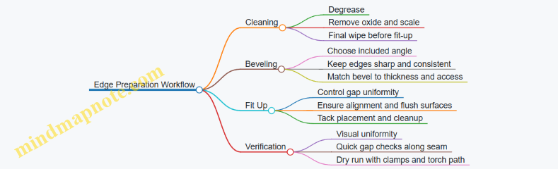
Verification and Micro-Adjustments Before Welding
Before you start the actual weld, do a short “dry” setup: clamp the parts, confirm access for the torch angle, and check that the bevel surfaces remain in contact where intended. If you see a gap that opens and closes along the seam, fix it now with clamps or shims; parameter changes can’t reliably correct mechanical inconsistency.
A simple rule: if you can slide a thin feeler gauge into the joint at one location, expect lack of fusion risk at similar locations. Fix the fit, then weld.
Common Mistakes and What to Do Instead
- Mistake: Cleaning only the visible face
- Instead: clean the bevel surfaces and the first few millimeters of the joint line.
- Mistake: Beveling with inconsistent tool pressure
- Instead: use a guide or stop block so the bevel angle stays repeatable.
- Mistake: Tack contamination inside the weld path
- Instead: clean tacks and remove any rough, oxidized edges before the final pass.
When edge preparation is consistent, the laser process becomes easier to tune. You spend less time chasing defects and more time building welds that look the same from one joint to the next.
5.4 Managing Thin Sheet Distortion with Laser Friendly Techniques
Thin sheet distortion is mostly a heat-and-constraint problem: the laser creates a small hot zone, the surrounding metal resists expansion, and the part “chooses” a new shape to relieve stress. With handheld laser welding, the cure is not just lower settings; it’s controlling where heat goes, how the joint is supported, and how the weld is sequenced.
Start with the Physics You Can Use
-
Contraction pulls the weld toward itself. After the weld cools, the solidified metal shrinks and drags nearby regions. If the sheet is free to move, it will warp; if it’s clamped, the stress concentrates and may still bow the sheet.
-
Heat input scales with speed and overlap. Slower travel and repeated passes add energy. For thin sheet, a small change in travel speed can shift you from “stable fusion” to “unwanted movement.”
-
Joint fit controls heat distribution. A tight, consistent gap reduces the need for extra energy to achieve fusion. Poor fit forces you to compensate, which increases distortion.
Prepare the Sheet So It Can’t Misbehave
- Clean to bare metal where the weld will be. Oil, oxide, and paint act like heat sinks or contamination sources. The practical result is more time spent “chasing” fusion.
- Use consistent fit-up. For lap joints, keep overlap uniform. For butt joints, aim for a narrow, repeatable gap. If you can’t hold the gap, you’ll end up adding energy and the sheet will pay the price.
- Plan for access. If your torch angle forces you to hover or correct mid-weld, you’ll create uneven heating. Position the part so your wrist motion stays steady.
Control Heat with Laser Friendly Welding Habits
- Prefer short weld segments over continuous runs. Stitch welding reduces the length of the hot zone at any moment. Think of it as giving the sheet time to cool before the next pull.
- Use a balanced sequence. For long seams, weld in alternating sections from the center outward. This spreads contraction forces instead of stacking them in one direction.
- Minimize unnecessary dwell. Pausing at the start and end of a seam often creates a “bulge” that later becomes a warp anchor.
- Keep standoff and focus consistent. Variations change spot size and effective energy density. A slightly larger spot can widen the weld and increase the area that contracts.
Fixturing That Actually Works
Fixturing should restrain movement without creating new stress risers.
- Clamp near the weld line, not far away. Distant clamps allow the sheet to flex during heating.
- Use soft interfaces where possible. Aluminum or copper pads under clamps reduce local denting and help maintain contact.
- Allow controlled expansion. If you fully lock the sheet in a way that prevents any movement, the stress has nowhere to go except into bending. A practical approach is to clamp firmly at key points while leaving small freedom elsewhere.
Choose Parameters with Distortion in Mind
A good starting point is “just enough” energy for full fusion.
- Increase travel speed before you increase power. If fusion is incomplete, raise power in small steps rather than slowing down aggressively.
- Reduce pass count. Multiple passes can be necessary for thickness or joint geometry, but each pass adds heat. When possible, aim for one clean pass with correct fit-up.
- Avoid excessive overlap of weld beads. Overlapping too much reheats already-welded metal and widens the contraction zone.
Use Simple Techniques to Flatten After Welding
Sometimes the sheet still moves. The goal is to correct it without creating new defects.
- Peen lightly on the weld bead side for mild steel. Gentle, controlled peening can counteract shrinkage. Stop when the sheet is flat; over-peening can thin the bead or create surface irregularities.
- Restrain during cooling. Keep the part clamped until it reaches a safe handling temperature. Releasing too early lets the sheet “set” in the warped shape.
- Heat straightening only when needed. If you must straighten, use localized, controlled heat and monitor continuously. Broad heating adds more distortion than it removes.
Example: Lap Joint on 1.0 mm Mild Steel
Setup: Clean overlap faces, clamp with pads 20–40 mm from the seam, and keep overlap uniform.
Technique: Weld in 15–25 mm stitches. Start at the center, then alternate left and right stitches. Avoid pausing at stitch ends.
Result logic: Each stitch creates a short contraction zone. Alternating sides balances pull forces, so the sheet doesn’t accumulate bending in one direction.
Example: Butt Joint on 0.8 mm Stainless Sheet
Setup: Ensure tight, consistent gap using a temporary tack fixture. Keep torch angle steady to avoid wandering.
Technique: Use a single pass if fusion is achieved; otherwise, do two light passes rather than one slow pass. Keep standoff consistent and avoid reheating the same track repeatedly.
Result logic: Stainless is less forgiving of contamination and inconsistent energy. Tight fit reduces the need for extra heat, which reduces warping.
Mind Map: Thin Sheet Distortion Control
Quick Checklist for the Next Thin Sheet Job
- Fit-up is consistent and clean.
- Welding is stitched or sequenced to avoid one long hot zone.
- Standoff and focus are stable.
- Clamps are near the seam and release happens after cooling.
- Parameters aim for full fusion with minimal extra heat.
5.5 Using Consumables and Filler Wire When Applicable
Handheld laser welding often works without filler wire, but consumables and filler can make the difference between “looks fine” and “holds under real use.” The key is to treat consumables as part of the process, not as an afterthought.
Consumables That Actually Matter
Start with the basics that change the weld pool and the surface around it:
- Shielding gas: Even when the system allows no-gas operation, gas can reduce oxidation and improve bead consistency on reactive metals like stainless and aluminum. If you see a dull, chalky surface after welding, gas coverage is usually the culprit.
- Lens protection: Spatter and vapor can cloud optics. Use the manufacturer’s recommended lens cover or protective window and replace it on schedule, not when the weld “starts looking weird.”
- Cleaning materials: Laser welding is picky about contamination. Use dedicated stainless brushes, lint-free wipes, and approved degreasers. Avoid touching cleaned surfaces with bare hands; oils transfer fast.
- Filler wire: Use it when you need to restore volume, bridge a gap, or control bead shape in joints that don’t fit tightly.
A practical rule: if your joint fit is tight and surfaces are clean, you can often weld without filler. If fit-up is inconsistent or the joint leaves a visible gap, filler becomes a tool for stability.
When Filler Wire Helps
Filler wire is most useful in these situations:
- Lap joints with variable overlap: A small gap can cause lack of fusion. Filler helps maintain continuity.
- Butt joints with imperfect edge alignment: Filler can bridge the mismatch while you keep travel speed steady.
- Thin sheet repairs: You may need a controlled amount of added metal to avoid a weak, narrow bead.
- Stainless and aluminum: These materials can benefit from filler when you want a smoother bead profile and better wetting.
If the joint is already well-fitted and you can achieve full fusion, adding filler can increase heat input and widen the weld. That’s not always bad, but it should be intentional.
Choosing Filler Wire and Consumables
Match filler to base metal and application requirements:
- Mild steel: Use filler wire compatible with the steel grade and intended load. For workshop jobs, “close match” is usually better than random assortment.
- Stainless steel: Choose wire that matches the alloy family to reduce corrosion issues. If you’re welding 304-like material, don’t grab a generic mild steel wire.
- Aluminum: Use aluminum filler designed for the alloy family. Aluminum filler that doesn’t match can create a bead that looks okay but behaves poorly under stress.
Consumables should also match the task:
- Gas type and flow: Use the recommended gas for the material. Too little flow can cause oxidation; too much can disturb shielding coverage depending on torch geometry.
- Wire diameter: Smaller wire is easier to control on thin sections. Larger wire adds metal quickly and can overfill.
Technique for Controlled Filler Addition
Filler wire works best when you treat it like a metered input, not a “more is better” lever.
- Set your baseline without filler: Weld a short test bead on the same material and thickness. Confirm penetration and bead shape.
- Introduce filler only after the pool is stable: Start the weld, establish a consistent pool, then feed wire smoothly.
- Feed rate matches travel speed: If you move fast, feed less. If you slow down, feed slightly more. The goal is a steady bead width, not a constant wire motion.
- Keep the wire tip clean: Contamination on the wire transfers into the weld pool.
- Avoid “dumping” wire at the start: The first second sets the bead profile. Add wire gradually once the pool is established.
A simple workshop check: after welding, compare bead width and penetration between “no filler” and “with filler” runs. If filler increases width but penetration stays shallow, the issue is likely joint fit or focus/standoff, not filler quantity.
Mind Map: Consumables and Filler Wire Use
Example: Lap Joint on Mild Steel Bracket
You’re welding a mild steel bracket with a lap overlap that varies by about 0.5 mm due to hand-made fit-up. Without filler, you get a bead that looks continuous but shows occasional weak spots when you bend the bracket.
Best practice:
- Clean both surfaces thoroughly.
- Run a short no-filler test to confirm penetration.
- Add filler wire only when the pool is stable.
- Feed at a rate that keeps bead width consistent across the overlap.
Result: the weld becomes more uniform because the filler bridges the small gaps that would otherwise create lack of fusion.
Example: Stainless Enclosure Seam
A stainless enclosure seam shows a dull, oxidized surface and inconsistent bead edges when welded without filler and with weak shielding.
Best practice:
- Verify shielding gas flow and coverage.
- Replace lens protection if spatter has reduced clarity.
- If fit-up is tight, try no filler first.
- If you still see uneven wetting, add a small amount of stainless-compatible filler with a controlled feed rate.
Result: the bead profile improves while the surface stays cleaner, because the process is addressing oxidation and wetting rather than just adding metal.
Example: Thin Aluminum Repair Patch
A thin aluminum patch has a small gap at the edges. Welding without filler creates a narrow bead that doesn’t fully tie into the base metal.
Best practice:
- Use the correct aluminum filler family.
- Start the weld, stabilize the pool, then feed wire gradually.
- Keep the wire diameter small to avoid overfilling.
Result: the filler restores continuity at the edge without turning the repair into a thick, heat-stressed lump.
6. Setup, Calibration, and First Welds
6.1 Unboxing, Inspection, and Initial System Checks
When the system arrives, treat the first hour like a calibration session for your eyes and habits. The goal is simple: confirm the package contents, verify nothing was damaged in transit, and establish a safe baseline before you ever touch a part.
Unboxing with a Checklist Mindset
Start by clearing a flat workspace with good lighting and enough room to lay components without stacking them. Keep the laser interlock key and any safety key separate from the rest of the kit so you don’t end up hunting for them mid-check.
Open the shipping cartons in this order: controller and power unit, then the handheld torch assembly, then cables and accessories. As you remove each item, compare it to the packing list and note any missing serial-numbered parts. If your system uses a separate shielding gas regulator, confirm it’s included before you proceed, because later checks depend on it.
A practical habit: photograph the labels and serial numbers before you connect anything. If you later need to identify a component, you’ll be glad you did.
Visual Inspection for Transit Damage
Look for three categories of issues: mechanical, optical, and electrical.
- Mechanical: Check torch housings, cable strain reliefs, and any connectors for dents, cracks, or loose fasteners. Tug gently on cable ends only at the connector body, not on the cable itself.
- Optical: Inspect the torch head window or protective lens area for chips, haze, or scratches. Even a small mark can change how the beam behaves.
- Electrical: Verify that power cables are intact, with no exposed conductors or crushed sections. If the system includes a cooling unit, check hoses for kinks and confirm fittings are seated.
If you find damage, stop. Don’t “test anyway” because a failed component can create misleading results later.
Cable Routing and Connection Verification
Before powering on, route cables so they won’t be pinched when you move the torch. A common mistake is looping the fiber or cable near the work area; that can create strain and inconsistent behavior.
Confirm that each connection is fully seated: power input, torch connector, and any sensor or interlock leads. If your system uses a quick-connect for shielding gas, ensure the seal surfaces are clean and aligned.
Safety Interlocks and Emergency Stop Checks
With the system still unpowered or in a safe state, verify that interlock mechanisms are present and move freely. Then confirm emergency stop behavior by checking that the control panel indicates an active stop condition when engaged.
Use the simplest test: attempt to start a laser operation with the interlock not satisfied. The system should refuse to fire. If it doesn’t, treat it as a stop-ship issue.
Cooling and Gas Readiness Checks
If your system uses water or recirculating cooling, verify the reservoir level and that the pump is primed according to the manual’s basic steps. Don’t run the laser without confirming flow, because overheating can damage internal components.
For shielding gas, confirm regulator settings are reachable and that the gas line is connected securely. Perform a quick leak check at fittings using the method your system specifies. If you don’t have a specified method, don’t improvise with open flames.
First Power-On and Control Panel Baseline
Power on and watch for stable startup indicators. Record any status messages exactly as shown, including error codes. A baseline log helps you distinguish “normal startup” from “something is off.”
Then run the system’s built-in diagnostics if available. If the system offers a “ready” state, confirm it only appears when cooling and interlocks are satisfied.
A small but useful step: set the control software to a known safe mode or default profile before any parameter entry. This prevents accidental high-energy settings during early testing.
Initial Test with Non-Contact Verification
Before welding anything, verify the torch alignment and aiming aids. If the system includes a visible aiming beam or guidance light, check that it points to the expected location relative to the work plane.
Do a non-contact motion check: move the torch through the range you plan to use and confirm cables don’t snag. This is where you catch routing problems without risking a part.
Mind Map: Unboxing and Initial Checks
Example: A Clean First-Hour Workflow
On a workbench dated two months ago, you can run a repeatable sequence: verify contents against the packing list, inspect the torch head window under bright light, route cables so they hang freely, confirm interlock refusal to start, check cooling flow status, connect gas and confirm fittings are tight, then power on and record the startup messages. Only after the system reaches a confirmed ready state do you perform a non-contact aiming check.
Example: What “Good” Looks Like
Good signs are specific: the system refuses to fire when an interlock is open, the control panel shows a stable ready state only after cooling is active, and the aiming indicator stays consistent when you move the torch within your normal working range. If any of these fail, stop and correct the setup before you attempt welding.
6.2 Installing and Verifying Shielding Gas Components
Handheld laser welding often needs shielding gas to keep the weld pool clean and the surface looking like you meant it. Even when your system supports “no gas” operation, installing the gas components correctly is still useful because it reduces variables during setup and troubleshooting.
Foundational Concepts Before You Touch Hardware
Shielding gas does two jobs at once: it displaces air around the weld and it stabilizes the weld surface by reducing oxidation. For that to work, the gas must reach the right area at the right flow rate, with minimal leaks and minimal turbulence. If the torch nozzle, standoff, and gas flow are mismatched, you can get inconsistent bead shape even when your laser parameters are unchanged.
Start by identifying what your system expects: the torch model, nozzle type, and whether it uses a dedicated gas line or a shared manifold. Confirm the recommended gas type for your materials (commonly argon or argon mixes) and note the typical flow range listed for your torch. If your workshop has multiple gases, label the cylinders clearly before installation so you don’t “solve” a weld problem with the wrong bottle.
Installing Gas Components Step by Step
-
Secure the cylinder and route the hose Place the cylinder upright and secure it so it cannot tip. Route the hose away from sharp edges, hot surfaces, and areas where it can be pinched by clamps or doors. A hose that gets kinked may still “work,” but it will create unstable flow.
-
Fit the regulator and set a safe starting pressure Install the regulator per the cylinder and torch requirements. Set the regulator to a low, safe starting pressure before connecting to the torch. This prevents sudden high-flow bursts when you open the valve.
-
Connect the gas line to the torch assembly Use the correct fittings and ensure the hose is fully seated. If your system uses quick-connect couplers, confirm the latch engages. For threaded fittings, avoid over-tightening; overtightening can damage seals and cause slow leaks that show up only after you’ve started welding.
-
Install the nozzle and verify standoff compatibility The nozzle directs gas where it matters. Install the nozzle specified for your torch and ensure it matches the intended standoff. If you change nozzles later, re-check gas behavior because the gas plume shape changes.
-
Check for leaks before powering the laser With the cylinder valve closed, connect everything and then open the valve slowly. Use an approved leak-check method (for example, a leak-detection solution on fittings) and watch for bubbles. Fix leaks before proceeding; a small leak can still ruin weld consistency.
Verifying Gas Flow and Coverage
Once installed, verification is about confirming three things: flow rate, delivery stability, and coverage at the weld zone.
-
Flow rate check at the torch Set the regulator to achieve the recommended flow range for your torch and material. If your system includes an inline flowmeter, observe it while the torch is held in its normal operating position. If the flowmeter reading changes when you move the torch, you likely have a hose restriction or a partially seated fitting.
-
Coverage check using a simple test Perform a short test on scrap with the laser at low energy settings. Watch the weld area for signs of oxidation on the bead surface and around the edges. If you see rapid discoloration or inconsistent bead wetting, the gas plume may be misdirected due to standoff, nozzle mismatch, or a partially blocked nozzle.
-
Stability check during motion Move the torch at your normal travel speed over scrap while keeping standoff consistent. Gas coverage should remain steady; if bead appearance changes with motion, check for hose drag, torch tilt, or nozzle obstruction.
Common Installation Mistakes and What They Look Like
- Wrong nozzle installed: bead surface shows uneven oxidation patterns across the weld.
- Kinked or pinched hose: flowmeter readings fluctuate; bead width varies even with steady laser settings.
- Slow leaks at fittings: weld quality degrades after a few minutes as pressure drops.
- Inconsistent standoff: gas coverage changes with torch height, causing alternating under- and over-protected regions.
Mind Map: Shielding Gas Installation and Verification
Example: Setting Up for Mild Steel on Scrap
You mount the cylinder, install the regulator, connect the hose to the torch, and fit the correct nozzle. After leak-checking, you set the regulator to the recommended flow range for your torch. You then run a short scrap test while holding standoff steady and moving at your usual speed. If the bead surface stays clean and the edges look uniformly protected, you can proceed to parameter tuning. If you see patchy discoloration, you pause and re-check nozzle seating and standoff before changing laser settings.
Example: Diagnosing Fluctuating Flow During Torch Movement
During a test pass, the flowmeter reading drops when you swing the torch toward the workpiece. You inspect the hose route and find a tight bend near the bench edge. After re-routing the hose to remove the bend, the flow reading stabilizes and the bead appearance becomes consistent. This confirms the issue was delivery stability, not laser parameters.
6.3 Setting Focus and Stand Off Including Practical Verification Methods
Handheld laser welding depends on two geometry choices: where the beam is focused and how far the nozzle sits from the work. Get those right and the weld pool behaves like it has a plan. Get them wrong and you’ll chase symptoms—spatter, shallow fusion, inconsistent bead width—without fixing the cause.
Foundational Concepts for Focus and Stand Off
Focus is the location along the beam path where the spot size is smallest. A smaller spot concentrates energy, which usually increases penetration but also narrows the process window. Stand off is the distance from the nozzle face (or protective window) to the work surface. Stand off affects the spot size at the metal and the beam’s ability to stay aligned with the joint.
In practice, your goal is not “maximum penetration.” Your goal is repeatable penetration and bead shape for the joint you’re welding. That means you must verify focus and stand off on the actual material, thickness, and surface condition you’ll use in production.
Setting Focus Using the Built-In Adjustment
Most compact systems provide a focus adjustment via a mechanical slide, a lens position setting, or a software parameter tied to a physical lens module. Start with the manufacturer’s baseline for your material class, then verify with a controlled test.
- Clean the work area where you’ll test. Oil, paint, and oxide change how the surface absorbs energy, which can masquerade as a focus error.
- Set stand off to the recommended value for your torch and lens configuration.
- Adjust focus to the baseline for the thickness range you’re targeting.
- Weld a short straight bead at a moderate speed using a consistent travel path.
Now inspect the bead cross-section if you can, or use surface indicators if you can’t. A good focus setting typically produces a stable bead width, smooth transitions at the edges, and a weld pool that wets into the joint rather than sitting on top.
Setting Stand Off for Stable Spot Size
Stand off is easy to mess up because it changes with hand height, part thickness, and how you rest your wrist. A practical approach is to treat stand off like a measurement you control, not a vibe you guess.
- Use a physical reference: a spacer block or a scrap plate with a marked height that matches your target stand off.
- Mark your torch position: a tape line on the torch body or a simple jig that limits how far you can lift.
- Maintain stand off during the entire pass: if you start close and end far, the spot size changes mid-weld and the bead will show it.
Practical Verification Methods That Actually Work
Verification Method 1 Bead Profile Check
Make three beads on the same scrap strip, changing only one variable each time.
- Bead A: baseline focus and baseline stand off
- Bead B: baseline focus, stand off increased by a small step
- Bead C: baseline stand off, focus shifted by one step
Compare bead width and edge wetting. If increasing stand off makes the bead wider but shallower, you’re losing energy density at the surface. If shifting focus changes penetration without widening excessively, you’re moving the spot relative to the metal.
Verification Method 2 Penetration Proxy with Backside View
For sheet and tube where you can access the backside, look for a consistent penetration mark.
- A stable penetration mark across the bead length suggests correct focus and controlled stand off.
- A penetration mark that fades at the start or end points to height drift.
If you can’t see the backside, you can still cut a small section from the test coupon and check the fusion depth.
Verification Method 3 Joint Wetting and Lack of Fusion Detection
On lap joints, lack of fusion often shows up as a visible line at the interface. Weld a short lap test with a fixed overlap and then inspect the interface.
- Good settings produce continuous wetting along the overlap.
- Poor focus or stand off often leaves a narrow region where the top surface melts but the interface doesn’t fully fuse.
Mind Map: Focus and Stand Off Verification
Common Mistakes and How to Correct Them
If your beads look fine on top but the joint doesn’t fuse, suspect focus placement first, then stand off. If the bead changes along its length, suspect stand off drift from hand height or torch resting habits. If you see inconsistent results across similar parts, suspect surface condition and fit-up cleanliness; focus and stand off can’t compensate for dirty or poorly aligned joints.
A simple rule for workshop life: after you set focus and stand off, verify with a short coupon test before you commit to the real part. It’s faster than reworking a finished bracket, and it keeps your process from turning into a guessing game.
6.4 Establishing Baseline Parameters for Each Material and Thickness
Baseline parameters are your starting map for repeatable welds. The goal is not to find “the one perfect setting,” but to establish a small set of settings that reliably produce a stable weld pool for a specific material and thickness. From there, you adjust with evidence rather than guesswork.
Step 1: Define the Test Envelope
Start by writing down three facts before touching the controls: material type, thickness, and joint style. For example, “mild steel, 1.5 mm, lap joint with 1 mm overlap.” Then add two constraints: whether you will use shielding gas and whether you will use any filler. These choices change how the weld pool behaves, so they belong in the baseline record.
A practical baseline envelope uses a narrow range of travel speeds and a single focus/stand-off condition. If you change focus and speed at the same time, you won’t know which lever caused the result.
Step 2: Choose a Starting Power and Focus
Use the manufacturer’s recommended starting power range for the material class, then pick a mid value within that range. If your system uses a focus position, set it to the recommended default for the thickness you’re testing.
Example: For stainless sheet around 1.2 mm, start at a mid power setting and keep focus at the default position. If the weld pool is too narrow and sits on top, you may need more power or slower travel. If it blows through, you likely need less power or faster travel.
Step 3: Set Travel Speed Using a Controlled Ladder
Create a small ladder of speeds, such as three settings: slow, medium, fast. Keep power and focus constant across the ladder. Weld short segments with the same torch angle and the same standoff.
What you’re looking for is a speed where the bead shows consistent wetting and penetration without excessive spatter. If the slow setting produces burn-through on thin material, discard it. If the fast setting produces a narrow bead with lack of fusion, discard it.
Step 4: Confirm Standoff and Torch Angle
Standoff and torch angle affect energy density and how the molten metal is supported by the shielding gas. Verify standoff with a simple physical check: mark a reference distance on a scrap plate and practice holding the torch so the mark aligns during travel.
Torch angle example: If you weld a lap joint and the bead consistently undercuts one side, reduce the angle slightly so the beam energy and molten metal flow are directed more evenly across the overlap.
Step 5: Decide on Shielding Gas Coverage
If your process uses shielding gas, treat it as part of the baseline, not an afterthought. Gas coverage influences porosity and surface appearance.
Example: On aluminum sheet, if you see pinholes in the bead center while the edges look fine, try improving gas coverage and ensuring the nozzle is not too far from the surface. If you are already at the correct standoff, the next adjustment is often travel speed rather than power.
Step 6: Record Baseline Results with Evidence
A baseline is only useful if you can reproduce it. Record: power, travel speed, focus position, standoff, torch angle, gas on/off and flow setting, and joint prep notes.
Then add two quick observations from each test bead:
- Bead wetting: does it smoothly connect to the edges?
- Penetration behavior: does it sit shallow, look balanced, or show signs of burn-through?
Mind Map: Baseline Parameter Workflow
Example: Baseline Setup for Mild Steel 1.5 mm Lap Joint
- Write: mild steel, 1.5 mm, lap joint, gas on, no filler.
- Set focus to the default for 1.5 mm and set standoff to the recommended value.
- Pick starting power at the mid value for mild steel.
- Weld three 30–50 mm beads at slow/medium/fast speeds.
- Choose the speed where the bead wets both edges and shows stable penetration without excessive spatter.
- Record the chosen settings as the baseline, then only adjust one variable for the next test (usually speed or power).
Example: Baseline Setup for Stainless Steel 0.8 mm Butt Joint
Thin stainless is unforgiving, so your ladder should be tighter. Keep power constant and use smaller speed steps. If the bead looks narrow and sits on top, slow down slightly. If it shows burn-through or a crater-like appearance, increase speed first before reducing power.
Practical Baseline Rule
When you find a setting that produces a stable bead, don’t immediately chase “more penetration.” First confirm repeatability by running the same bead on a second scrap piece with identical prep. If the second piece matches, you have a baseline worth using.
6.5 Performing Controlled Test Beads and Documenting Results
Controlled test beads are your fastest way to turn “it should work” into “it does work” for a specific thickness, joint fit, and setup. The goal is not to make pretty welds; it’s to map process settings to observable outcomes so you can repeat them later.
Define the Test Scope Before You Strike an Arc
Start by writing down what you are actually testing. Laser welding is sensitive to small changes, so keep the scope tight:
- One material grade per test set (for example, mild steel sheet from the same supplier batch).
- One thickness range per test set (for example, 1.0 mm and 1.5 mm separately).
- One joint style per test set (for example, lap joint with a fixed overlap).
- One fixturing method per test set (for example, clamped flat on a steel backing plate).
A simple rule: if you change more than one variable, you lose the ability to explain why the result changed.
Prepare Coupons with Realistic Fit Up
Use coupons that match your job conditions. If your production parts have mill scale, use it. If your parts are cleaned, clean the coupons the same way.
For each coupon set, keep these consistent:
- Surface condition: cleaned to the same level, same direction of wiping.
- Joint gap or overlap: measure once, then maintain with the same spacer or jig.
- Backing support: same plate thickness and same contact area.
A practical example: if you plan to weld a lap seam on a bracket, make test coupons as lap seams too, not butt joints. Laser behavior changes when the melt has nowhere to go.
Establish a Baseline Parameter Set
Pick a baseline from the machine’s starting guidance, then reduce uncertainty by doing a small, structured sweep.
Document baseline settings in a table before welding:
- Laser power
- Travel speed
- Focus position or stand off
- Shielding gas on/off and flow rate
- Torch angle and travel direction
- Any assist features such as filler wire usage
If your system uses a focus offset, treat it like a controlled variable. A focus change can mimic a power change, which is why you record both.
Run a Minimal Matrix of Test Beads
Use a matrix that changes one main variable at a time. A common approach is:
- Keep power fixed, vary speed in 3 steps.
- Then keep speed fixed, vary power in 3 steps.
Example for 1.5 mm mild steel lap coupons:
- Speed steps: slow, medium, fast (three settings).
- Power steps: low, baseline, high (three settings).
For each bead, label the coupon clearly and record the order you ran them. That matters because optics cleaning, gas flow, and operator consistency can drift over time.
Observe Weld Pool Behavior with Simple, Repeatable Checks
After each bead, inspect and measure using the same checklist:
- Bead width and uniformity
- Evidence of penetration at the edge (if accessible)
- Undercut or excessive crown
- Spatter level on surrounding metal
- Surface discoloration pattern
A useful trick: take one photo per coupon from the same angle and distance. Even if you later measure with calipers, the photo helps you spot trends like “spatter increases as speed decreases.”
Document Results in a Way You Can Actually Use
Create a record that links settings to outcomes. Include both numbers and plain-language notes.
Example record entry:
- Coupon ID: MS-1.5-L1
- Settings: Power 1200 W, Speed 18 mm/s, Focus 0 mm, Gas 8 L/min
- Observations: penetration good at lap edge, bead width moderate, minimal spatter
- Decision: keep for next matrix
If you see a defect, record the most likely cause you can support from the test. For instance, if you get lack of fusion at the lap edge while bead width stays narrow, you likely need more energy density (often slower speed or slightly higher power), not a random change to torch angle.
Mind Map: Controlled Test Beads and Documentation
A Short Example Sequence That Stays Systematic
Run 9 coupons for a first pass on 1.5 mm mild steel lap joints.
- Coupon MS-1.5-S1 to S3: power fixed at baseline, speed slow/medium/fast.
- Coupon MS-1.5-P1 to P3: speed fixed at the best of S1–S3, power low/baseline/high.
- Choose the best two coupons based on edge penetration and minimal spatter.
- Lock those settings as your “starting recipe” for the first production-like job.
This sequence prevents the common mistake of picking a setting because it looks good on top while the lap edge tells a different story.
7. Technique for Consistent Beads and Penetration
7.1 Hand Motion Control Including Travel Speed and Standoff Consistency
Handheld laser welding is mostly a motion problem with a physics payoff. Your goal is to make the laser energy arrive at the joint in a predictable way, so the weld pool forms the same size and shape each pass. Two motion variables dominate: travel speed and standoff (the distance from the nozzle or optics reference point to the work surface). If either drifts, the effective energy density changes, and the weld responds.
Foundational Motion Model
Think of the process as energy per unit length. If your laser power is fixed, then changing travel speed changes how much energy lands on each millimeter of joint. Slower travel increases energy per length, which tends to increase penetration and bead width but also raises the risk of burn-through on thin sheet. Faster travel reduces energy per length, which can lead to shallow fusion or a narrow, ropey bead.
Standoff consistency affects how the beam focuses on the work. If the standoff grows, the beam may defocus slightly, reducing peak intensity at the surface and often widening the bead while reducing penetration. If the standoff shrinks, you can overshoot the focus and get a different pool shape, sometimes with a flatter bead and more surface melting than expected.
Travel Speed Control with Practical Cues
Start by choosing a target speed that you can repeat without “chasing” the puddle. A good workshop habit is to weld a short test line while watching the bead profile after the fact, not while you’re still moving. Use these cues:
- Too slow: bead looks wide and glossy, edges may sag, and thin material can show a dark spot or sudden thinning.
- Too fast: bead looks narrow, with possible lack of fusion at the edges; the surface may appear grainy rather than smooth.
A simple method for consistency is to mark a reference length on scrap and time your movement with a stopwatch. For example, if you intend to cover 50 mm, practice until you can hit the same time three times in a row. Then weld the actual joint with the same motion tempo.
Standoff Consistency with a Repeatable Reference
Standoff drift usually comes from body position changes, torch rotation, or uneven work surfaces. Fix it by creating a physical reference you can feel and see.
- Use a consistent torch height: rest your wrist or forearm on a stable edge so your hand moves forward more than up and down.
- Maintain a fixed torch angle: if the torch tilts, the effective standoff changes even if your hand “looks” level.
- Plan for steps: if you must cross a seam or bracket, slow slightly before the step and keep the nozzle height controlled rather than letting it float.
A practical check is to weld a short line on scrap and then measure bead width and penetration indicators (for example, by sectioning a test coupon). If bead width changes while your speed stays similar, standoff is likely drifting.
Integrated Control Loop During Welding
Use a two-variable mindset: adjust one variable at a time. If penetration is low, first confirm standoff is stable; then reduce speed in small increments. If penetration is too deep or burn-through appears, increase speed first and only then revisit standoff.
When you change speed, do not also change torch angle or standoff in the same pass. Otherwise you’ll “fix” the wrong thing and learn nothing.
Mind Map: Motion Variables and Their Weld Effects
Example: Mild Steel Tube to Plate
You’re welding a 2 mm wall tube to a 3 mm plate. The joint is tight, and you want consistent fusion without blowing through the plate.
- Baseline test: weld a 30 mm scrap joint at a moderate speed while holding standoff constant using a forearm rest.
- Inspect: if the bead is wide but penetration is shallow, slow down slightly while keeping standoff unchanged.
- If burn-through appears: increase speed in small steps. Then re-check standoff by comparing bead width across the same length; if width varies, your height is drifting.
A small but important detail: when you start the weld, your hand often accelerates from rest. That first 5–10 mm can end up slower than the rest. Practice starting with the same tempo you’ll maintain, so the beginning doesn’t become a “special case” weld.
Example: Thin Stainless Sheet Repair Patch
Thin stainless punishes inconsistent standoff. Suppose you’re filling a small gap with a patch and you notice the bead is smooth in the middle but uneven at the ends.
- If the ends look flatter and less fused, your standoff likely increases as you approach the end of the line.
- Fix it by anchoring your wrist and planning your stop point so you don’t lift the torch to “finish cleanly.” Finish by maintaining height through the last millimeter, then stop.
In both examples, the winning move is the same: make travel speed and standoff repeatable, then adjust only one at a time. The weld pool will follow your consistency, not your intentions.
7.2 Torch Angle and Work Angle for Stable Weld Pools
A stable weld pool is mostly about geometry: where the laser energy enters, how the molten metal is guided, and how gravity and surface tension behave while you move. Torch angle and work angle control those forces, so the same parameter set can look consistent—or mysteriously different—depending on how you hold the torch.
Foundational Geometry
Torch angle is the angle between the torch axis and the direction of travel. Work angle is the angle between the torch axis and the work surface normal (or equivalently, how “tilted” the torch is toward or away from the plate).
Start with a simple rule: keep the torch axis pointing into the weld pool, not at the side of it. If you aim too far ahead, the pool forms and then runs out from under the beam. If you aim too far sideways, the beam digs a narrow channel while the pool refuses to spread.
A practical way to think about it: the beam is a heat source with a preferred direction, and the molten metal is a fluid that wants to flow downhill. Your angles decide whether the fluid flows smoothly into the path you’re about to weld.
Why Angles Affect Penetration and Bead Shape
When the torch angle is correct, the molten pool receives energy while it is already moving in the direction of travel. That supports consistent penetration and reduces the “start-stop” feeling where the bead changes shape mid-stroke.
If the torch is too steep relative to the travel direction, the pool tends to lag behind the beam. You’ll often see a narrower bead with a tendency toward lack of fusion at the leading edge.
If the torch is too shallow, the pool can spread wider than intended. That increases the chance of undercut at the edges because the surface flow outruns the solidification.
Work angle also matters because it changes how the keyhole—when present—stays centered. A small tilt can shift the keyhole toward one side, which shows up as uneven penetration or a bead that looks “biased” to one edge.
Mind Map: Angle Effects and What You See
Setting Angles Without Guesswork
- Pick a reference line. Mark the joint centerline on scrap. Your torch should track that line, not hover “near” it.
- Set standoff first. Even perfect angles won’t help if the beam focus wanders. Establish a consistent distance, then adjust angles.
- Use a two-point check. Hold the torch at the start position and at the midpoint of a planned 50–100 mm test run. If the torch angle changes between those points, the bead will too.
- Move with the same posture. Most angle drift comes from wrist-only motion. Use forearm motion for travel and reserve wrist motion for fine alignment.
Example: Mild Steel Butt Joint on Thin Plate
Goal: consistent penetration without burn-through.
- Setup: Clean edges, fit-up with minimal gap, and start with a conservative parameter baseline.
- Angle choice: Use a moderate torch angle into the travel direction and a work angle that keeps the beam centered on the joint line.
- Test run: Weld 50 mm on scrap. Inspect the leading edge of the bead.
If you see lack of fusion at the leading edge: reduce the steepness of the torch angle slightly so the pool can move with the beam.
If you see undercut on one side: adjust work angle to re-center the keyhole and reduce the tendency for the molten metal to wash away from that edge.
Example: Stainless Sheet Lap Joint
Lap joints are forgiving about alignment but sensitive to overheating at the overlap edges.
- Setup: Ensure the upper sheet sits flat; any gap acts like a heat sink that changes pool behavior.
- Angle choice: Keep the torch angle steady and avoid tilting so far that the beam preferentially heats one overlap edge.
If the overlap edge looks over-melted: reduce the tendency to “aim at the side” by bringing the torch axis closer to the direction that feeds the pool forward.
Advanced Detail: Keeping Angles Stable While Speed Changes
Even if you keep the same posture, changing travel speed changes the pool’s size and lifetime. A faster pass shrinks the pool, making it more sensitive to angle errors; a slower pass enlarges it, increasing the chance of edge wash.
So when you adjust speed, re-check angles at the start and midpoint. If the bead suddenly becomes asymmetric after a speed change, treat it as an angle stability issue first, not a parameter mystery.
Quick Checklist Before You Commit to the Real Part
- Torch axis points into the weld pool direction.
- Work angle keeps the fusion line centered.
- Standoff is consistent across the stroke.
- Start and midpoint angles match.
- Bead symmetry and leading-edge fusion look normal on scrap.
When these hold, the weld pool behaves like a predictable fluid under a predictable heat source. The torch stops being a variable and becomes a tool.
7.3 Overlap Strategies Including Weave and Stringer Approaches
Overlap is how you control how one pass blends into the next. In handheld laser welding, the overlap you choose affects bead width, heat distribution, and defect risk. Think of it as “how much you trust the previous pass to still be there” when the torch moves forward.
Foundational Idea: Overlap as Heat Budgeting
Laser welding is sensitive to heat input because the weld pool is small and short-lived. If you overlap too little, each pass behaves like a separate weld with gaps or lack of fusion. If you overlap too much, you keep reheating the same zone, which can widen the bead, increase penetration variability, and raise the chance of burn-through on thin material.
A simple rule of thumb for planning is to start with a target bead width, then choose overlap so the combined passes cover that width without stacking excessive heat. For example, if your test bead is about 6 mm wide and your joint needs a 7–8 mm effective width, you typically want each new pass to cover roughly half to two-thirds of the previous bead width.
Stringer Approach: Straight Passes with Controlled Overlap
Stringer welding means moving in a straight line with minimal lateral motion. It’s the go-to choice when you want predictable penetration and when joint fit is consistent.
Best use cases
- Thin sheet where you want to avoid lateral heat spreading
- Tight root access where you need the beam to stay centered
- Repairs where you want to avoid widening the damaged area
How to set overlap
- Make a short test on scrap at your baseline parameters.
- Measure bead width and look for fusion at the edges.
- Adjust overlap by changing the lateral spacing between passes.
Concrete example Welding a 1.5 mm mild steel lap joint: you run two straight passes. If the first pass bead measures 5 mm wide and you place the second pass so it overlaps about 2.5–3.0 mm, the combined bead tends to fill the lap interface without turning the top surface into a crater. If you only overlap 1 mm, you often see a faint line at the interface after grinding.
Weave Approach: Controlled Side-To-Side Motion
Weaving adds lateral motion while maintaining forward travel. The goal is to distribute heat across the joint edges and improve sidewall wetting, especially when the joint is slightly wider than your beam spot or when you need to bridge small fit-up gaps.
Best use cases
- Wider joints where a single stringer leaves cold edges
- Slightly inconsistent fit-up where you need forgiveness
- Filling a shallow groove where you want a broader bead profile
How to set weave geometry Weave behavior is defined by three practical parameters:
- Amplitude: how far you move side to side
- Frequency or cycle rate: how quickly you complete each side-to-side motion
- Forward speed: how fast you advance while weaving
A useful way to avoid chaos is to keep amplitude modest and let overlap do the work. If amplitude is too large, you can overheat the edges and underheat the center, which looks like a bead that is wide but not well fused.
Concrete example Stitching a 3 mm stainless butt joint with a shallow gap: you start with a weave amplitude that is about half the measured bead width from your stringer test. If your stringer bead width is 4 mm, begin with about 2 mm amplitude. Run a short section and check whether both edges show consistent wetting after light grinding. If the center is underfilled, reduce forward speed slightly or increase overlap by adjusting amplitude upward by a small amount.
Choosing Between Weave and Stringer Without Guessing
Use stringer when you want “centered energy.” Use weave when you need “edge coverage.” The decision becomes easier if you evaluate what’s missing in your test weld.
- If you see lack of fusion at the sides, weave often helps because it spends time near the edges.
- If you see excess penetration or burn-through, stringer usually helps because it limits lateral heat spread.
- If you see inconsistent bead width, check standoff and travel steadiness before changing weave patterns.
Overlap Planning for Multi-Pass Welds
Multi-pass welds combine overlap in two ways: overlap between passes and overlap within a weave cycle.
Pass-to-pass overlap
- For stringers, overlap is mainly controlled by lateral spacing.
- For weaves, pass-to-pass overlap still matters, because each pass has its own effective bead footprint.
Within-pass overlap
- In weaving, the torch revisits the same lateral positions each cycle.
- If the cycle rate is too slow relative to forward speed, you can create a scalloped profile with uneven fusion.
A practical method is to keep your weave cycle consistent and adjust only one variable at a time during testing: first forward speed, then amplitude, then pass spacing.
Mind Map: Overlap Strategies for Weave and Stringer
Quick Troubleshooting Map for Overlap Problems
If your bead looks good in the middle but fails at the edges, increase effective overlap by either adding a small weave amplitude or reducing pass spacing. If the bead is too wide or the underside shows excessive penetration, reduce overlap by tightening pass spacing and switching toward stringer motion. When in doubt, run a short test coupon and measure bead width before changing multiple settings at once—your future self will thank you.
7.4 Managing Heat Without Burn Through on Thin Sections
Thin sections fail in predictable ways: the weld pool grows faster than the metal can conduct heat away, and then the laser energy does exactly what it’s designed to do—creates a hole. The goal is not “less welding,” but controlled heat input, stable focus, and joint practices that keep the molten area small.
Foundational Heat Control Concepts
Start with the simple relationship: heat input rises when you increase power, slow travel speed, or reduce effective spot size. On thin sheet, the margin between “good penetration” and “burn through” is small, so you must control all three.
-
Power sets the energy available per unit time. If you see the bead suddenly widening or the backside starting to glow, reduce power before you change anything else.
-
Travel speed controls how long the spot stays on one location. A small speed reduction can be the difference between a narrow, stable keyhole and a runaway melt.
-
Focus and standoff determine where the energy concentrates. If focus drifts, the effective spot grows and the process can shift from “deep and narrow” to “wide and shallow,” which often increases burn-through risk.
-
Joint fit and gap matter because a gap encourages the laser to couple energy into air and edges, destabilizing the pool. Tight fit helps the pool stay where you want it.
Practical Setup Checks Before You Weld
Before touching parameters, verify three things that commonly cause burn through even when settings look reasonable.
- Clean metal: Oil, mill scale, and paint change absorption and can create uneven heating. Wipe with a solvent-safe cleaner and remove surface oxides where practical.
- Consistent standoff: Use a physical reference or a torch guide so the nozzle-to-surface distance stays constant along the seam.
- Workpiece support: Thin sheet should be backed by a stable surface or fixture that prevents sagging. If the sheet flexes, the focus effectively changes mid-weld.
Parameter Tuning Strategy That Works in Real Shops
Use a small, repeatable tuning plan rather than random adjustments.
- Begin with a conservative baseline for the thinnest section you plan to weld.
- Run a short test seam and inspect the bead width and backside condition.
- Adjust one variable at a time:
- If you get burn through: reduce power slightly, then increase speed slightly.
- If you get lack of fusion: increase power modestly or slow speed slightly, but only after confirming focus and joint fit.
A useful rule of thumb for thin work is to prioritize speed and stability over chasing penetration. A slightly smaller penetration that stays intact is usually better than a deeper weld that turns into a hole.
Technique Choices That Reduce Melt Volume
Even with good parameters, technique controls how heat spreads.
- Use a straight stringer when possible: Weaving increases dwell time at the edges and can widen the melt. For thin sheet, start with a simple line.
- Keep torch angle consistent: A consistent angle helps the keyhole stay centered. If the angle changes, the pool can migrate and thin spots can fail.
- Avoid long continuous runs: For longer seams, use short segments with brief pauses to let heat conduct into the surrounding metal. The pause is not a “cooling break” for drama; it’s a way to prevent cumulative heat from stacking up.
Mind Map: Heat Management on Thin Sections
Example: Thin Mild Steel Lap Joint
You’re welding 1.0 mm mild steel lap joints. The first test shows a bead that looks fine on top but leaves a small backside opening near the start.
- Observation: Burn through begins early, suggesting the torch is starting with a slightly higher effective dwell or the sheet is flexing at the start.
- Fixes:
- Increase travel speed by a small step.
- Reduce power slightly.
- Add a fixture or clamp that prevents the sheet from lifting as you start.
- Keep the torch moving before the laser reaches full coupling, so the start doesn’t linger.
After changes, the bead remains narrow and the backside shows full fusion without a hole.
Example: Thin Stainless Sheet with Unstable Pool
On 0.8 mm stainless, the pool sometimes looks “wet” and then suddenly opens.
- Observation: Stainless is less forgiving of inconsistent fit and surface condition. A small gap can cause the pool to destabilize.
- Fixes:
- Improve fit-up with tack welds or a jig.
- Confirm standoff consistency along the seam.
- Use stringer passes and avoid weaving until you can reproduce stable bead shape.
- If the bead widens, reduce power before changing speed.
The weld becomes repeatable, with consistent fusion and no backside openings.
Quick Diagnostic Checklist
If burn through happens, check in this order:
- Standoff and focus stability
- Joint gap and cleanliness
- Travel speed too slow
- Power too high
- Technique dwell from weaving or inconsistent angle
- Cumulative heat from long continuous runs
Managing thin sections is mostly disciplined control: stable setup, one-variable tuning, and technique that doesn’t add extra dwell time. When those are in place, burn through becomes a solvable problem rather than a surprise.
7.5 Troubleshooting Bead Shape Including Spatter and Undercut
Bead shape problems usually come from a small set of causes: energy delivery, torch position, shielding coverage, and joint fit. The fastest way to troubleshoot is to change one variable at a time while keeping a written baseline. Start with a simple observation: spatter is mostly about how the weld pool is behaving at the surface, while undercut is mostly about how the pool wets the edges.
Mind Map: Bead Shape Symptoms to Likely Causes
Spatter Diagnosis and Fixes
Spatter often shows up as small droplets around the bead, sometimes with a rough, pebbly surface. If spatter increases when you slow down, the weld pool is likely staying too long in one spot, overheating the surface and ejecting material. Try increasing travel speed slightly while keeping power constant, then repeat with a small step in power if needed.
If spatter is worst at the start of a run, the torch may be entering the joint too abruptly or the standoff may be inconsistent. Use a consistent lead-in: begin on a scrap tab or at the edge of the joint, establish the pool, then continue. Also check that the nozzle and lens area are clean; contamination can change how the beam couples into the metal.
Shielding-related spatter is usually accompanied by discoloration and a duller bead surface. Verify gas flow with the regulator settings you normally use for that thickness, and confirm the nozzle is not too far from the work. Even a good parameter set can fail if there’s a draft. If you see spatter that looks “dry” and the bead looks oxidized, treat shielding first: clean the surface, confirm gas coverage, and reduce airflow across the weld path.
Undercut Diagnosis and Fixes
Undercut is a groove melted into the edge of the weld that does not get filled. It often appears when the center of the bead is getting energy but the edges are not wetting. A common cause is excessive travel speed: the pool becomes narrow and cannot climb the sidewalls. Slow down in small increments and watch whether the bead width increases and the edge groove disappears.
Another frequent cause is torch height. If your standoff is too large, the beam spot spreads and the energy density at the edges drops, leaving the sidewalls under-wetted. Bring the torch to your verified standoff and keep it consistent. If you cannot maintain standoff due to part geometry, use fixtures or a simple rest so your hand motion doesn’t turn into a height-changing act.
Torch angle matters too. If the torch is too steep, the pool tends to run forward and the edges lag behind. Adjust toward a flatter work angle so the pool has a better chance to wet both edges. If the joint has a gap or poor fit-up, the edge may not be supported by the molten pool. In that case, fix the fit: clamp tighter, re-prep edges, or use a backing strip where appropriate.
Systematic Troubleshooting Workflow
- Confirm the baseline: thickness, material, joint type, and your last known-good parameter set.
- Inspect the surface: oil, mill scale, paint, and oxide can cause both spatter and poor wetting.
- Check shielding and standoff: verify gas flow and keep nozzle distance consistent.
- Run a controlled test on scrap: change only one variable (speed, power, focus, or angle).
- Compare bead width and edge profile: spatter points to pool instability; undercut points to edge wetting.
- Lock the technique: once corrected, repeat the same motion on a second scrap coupon to confirm repeatability.
Example: Fixing Spatter on Mild Steel Tube to Plate
You weld a 2 mm tube to 2 mm plate and see heavy spatter plus a slightly rough bead. Start by cleaning both mating surfaces and confirming gas flow. Then increase travel speed by a small step while keeping power and focus unchanged. If spatter reduces but the bead still looks unstable, lower power slightly and keep the same speed. Finally, check torch angle: if it was very steep, flatten it a bit so the pool spreads rather than “punching” forward.
Example: Fixing Undercut on Stainless Sheet Overlap
You notice a clean center bead but a visible groove along one edge. First, slow travel speed slightly to widen the bead and improve sidewall wetting. If undercut persists, reduce standoff by bringing the torch closer to the work while maintaining your focus setting. If the joint fit has a small gap, clamp the overlap tighter; undercut often disappears once the edge is supported.
Quick Reference Mind Map: What to Change First
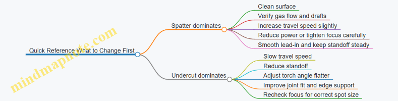
When you treat spatter and undercut as different symptoms with different root causes, troubleshooting becomes predictable. Keep the changes small, document what you altered, and let the bead tell you which knob to turn next.
8. Welding Procedures for Common Workshop Jobs
8.1 Welding Mild Steel Tube to Plate for Frames and Brackets
Handheld laser welding can join tube to plate with less heat spread than MIG, which helps when you’re building frames and brackets that must stay square. The key is to treat the joint like a geometry problem first, then a settings problem.
Joint Basics That Make Laser Welding Behave
A common frame joint is a tube end or tube side welded to a plate. For laser welding, the most reliable approach is a tight fit-up and a joint that gives the beam a clear path to the interface.
- Tube to plate alignment: Aim for consistent standoff and a predictable gap. If the tube sits proud or dips, the beam energy concentrates unevenly and the bead shape changes.
- Gap tolerance: Laser welding is less forgiving than some arc processes. A small gap can help fusion, but a larger gap often turns into lack of fusion or narrow, weak welds.
- Joint type choice: For thin plate, a lap-style contact (tube touching plate with a small overlap) often welds more consistently than a butt joint that relies on perfect edge contact.
Mind Map: Tube to Plate Welding Workflow
Setup Steps That Prevent Most Headaches
- Prep the metal like you mean it. Remove mill scale, paint, and oil at least where the beam will land. A quick wipe is not the same as removing residue; residue can create porosity.
- Dry fit and clamp. Use a fixture or at least two clamps to control rotation. For frames, check squareness before welding; laser welding won’t “fix” misalignment.
- Verify focus and standoff. If your system uses a fixed focus lens, confirm the working distance with a simple gauge or the manufacturer’s method. Inconsistent standoff changes spot size and penetration.
- Choose shielding gas based on your setup. If your torch uses gas, keep flow steady. If you’re welding in a drafty area, shielding coverage becomes inconsistent.
Technique for a Strong, Repeatable Bead
A tube-to-plate weld is usually strongest when the bead ties into both surfaces without digging a trench.
- Torch angle: Keep the beam aimed so the weld pool wets the plate edge and climbs slightly onto the tube. A shallow angle can under-wet the plate; a steep angle can under-wet the tube.
- Travel path: Use a straight stringer for short brackets. For longer seams, consider a controlled pattern that maintains overlap while avoiding heat buildup.
- End control: Start slightly ahead of the joint and stop slightly after. If you pause at the ends, you may increase penetration and create a notch that becomes a stress riser.
Example: Small Bracket with 25 mm Tube on 3 mm Plate
Assume mild steel tube around 25 mm OD and plate around 3 mm thick.
- Fit-up: Tube touching plate with a near-zero gap. Clamp to prevent rocking.
- First test: Make a 30–50 mm trial weld. Inspect the bead for a smooth transition at the plate edge and a consistent width along the seam.
- Parameter tuning logic:
- If the bead looks narrow and the plate edge doesn’t wet, increase energy (often by reducing travel speed first).
- If you see excessive penetration or burn-through marks on the plate, reduce energy (increase travel speed or reduce power).
- If you see pinholes, revisit cleaning and shielding coverage.
Example: Frame Corner with Two Tube Sides
For a corner, weld one side, then the other, rather than trying to complete everything in one pass.
- Sequence: Tack both sides first, then weld the longer seam on one face. After it cools enough to reduce movement, weld the second face.
- Why it matters: Tube corners can pull as the weld cools. Sequencing reduces the chance that the corner opens up.
Quality Checks That Match Real Use
- Visual: Look for consistent bead width and no obvious lack of fusion at the plate edge. Undercut on the tube edge is a sign your pool isn’t wetting correctly.
- Mechanical check: For brackets, a simple bend or pry test on a scrap sample from the same batch can reveal weak fusion before you commit to production.
Mind Map: Common Defects and Fixes
Practical Checklist Before You Weld the Real Part
- Surfaces cleaned where the beam will land
- Tube clamped square to plate
- Focus and standoff verified
- Shielding gas flow stable
- Trial weld made and inspected
- Weld sequence planned for corners and multi-side joints
When these steps are consistent, tube-to-plate welds come out predictable: penetration where you want it, wetting on both members, and fewer surprises when the bracket gets loaded.
8.2 Welding Stainless Steel for Enclosures and Food Service Parts
Stainless steel weld quality is mostly about control: clean surfaces, stable shielding, and parameters that match thickness and joint geometry. Handheld laser welding is fast, so the usual “slow down and hope” habits don’t work as well—small setup errors show up immediately in the bead.
Core Concepts That Drive Weld Quality
Stainless Steel Behavior You Must Plan For
Stainless grades differ in how they respond to heat. Austenitic grades (like 304 and 316) tolerate many workshop conditions, but they still form heat-affected zones that can change corrosion resistance if the weld area is contaminated or overheated. Ferritic and martensitic grades can be more sensitive to cracking, so you treat them with extra care on fit-up and parameter selection.
Corrosion Resistance Depends on Cleanliness and Shielding
For food service enclosures, the weld zone must be free of oils, oxide films, and residue. Laser welding can be forgiving on distortion, but it is not forgiving on contamination: fingerprints and cutting fluids can create porosity or surface defects that are hard to clean later.
Joint Fit-Up Controls Penetration
Laser energy is concentrated, so gaps and misalignment can lead to lack of fusion. For thin sheet, even a small edge mismatch can cause burn-through on one side and under-welding on the other.
Workshop Setup That Prevents Common Failures
Material Handling and Surface Prep
- Degrease both sides of the joint line. A simple wipe with a dedicated stainless-safe cleaner is usually enough.
- Remove oxide and discoloration from the weld path. Light sanding or a stainless brush works if it doesn’t leave carbon steel debris.
- Dry the parts before welding. Moisture can contribute to porosity.
Example: If you’re welding a 1.0 mm 304 enclosure seam, wipe the edges, then do a quick visual check for rainbow discoloration. If you see it, clean again before you start.
Shielding Gas Coverage and Flow
Even when the torch is compact, shielding is what keeps the molten pool from reacting with air. Use the recommended gas and flow range for your system, and keep the nozzle height consistent.
Best practice: Do a short test weld on scrap from the same sheet batch. If the bead surface looks rough or shows excessive oxidation, adjust shielding coverage before welding the actual enclosure.
Focus and Standoff Consistency
Focus position and standoff affect energy density and bead width. Mark a repeatable torch height reference on your fixture so you don’t “eyeball” it every pass.
Parameter Selection from Thickness and Joint Type
Start with Test Coupons
Use a small coupon set: same grade, same thickness, same joint prep. Change one variable at a time—typically speed first, then power—so you can interpret results.
Typical Process Logic
- Thin sheet: prioritize stable penetration without burn-through; keep travel speed high enough to avoid overheating.
- Thicker sections: allow more energy or slower travel to reach full fusion, but watch for excessive bead width that can trap contaminants.
Example: For a 1.2 mm 316 bracket, begin with a moderate power and a speed that produces a smooth, continuous bead with minimal spatter. If you see a crater-like end or inconsistent fusion, reduce speed slightly and verify fit-up.
Technique for Enclosure Seams and Food Service Parts
Travel Path and Torch Angle
Keep the torch angle consistent so the beam and shielding remain aligned with the pool. For long seams, use a steady travel path and avoid sudden starts and stops.
Best practice: Start the weld on a scrap tab or a hidden edge. This prevents a “first-second” defect from landing on the visible enclosure face.
Tack Strategy for Thin Assemblies
Tacks should be small and positioned to minimize distortion. If the seam opens during welding, you’ll get lack of fusion at the gap.
Example: For a box enclosure corner, place two tacks 20–30 mm apart, then weld the corner in one direction. If you weld both sides without controlling the corner fit, the panel can pull and create a visible step.
Managing Heat for Clean Surfaces
Laser welding is fast, but repeated passes can still overheat localized areas. If you need multiple passes, let the part cool enough to keep discoloration minimal.
Quality Checks That Match Real Use
Visual and Surface Integrity
Inspect for continuous bead appearance, minimal undercut, and absence of surface pits. For food service parts, prioritize smoothness where cleaning tools will contact the surface.
Simple Mechanical Verification
For enclosure panels, a light bend or peel check on a test coupon can confirm fusion quality. If the bead flakes or separates, the issue is usually fit-up or insufficient energy.
Cleaning After Welding
Remove any residue promptly. If you used stainless-safe brushes, avoid mixing carbon steel tools with stainless parts.
Mind Map: Welding Stainless Steel for Enclosures and Food Service Parts
Example: Corner Seam on a 1.0 mm 304 Enclosure
- Prep: degrease, then remove oxide along the corner line.
- Fit: clamp the corner so the gap is near zero.
- Shielding: set nozzle height to your reference mark.
- Test: weld a short 30 mm coupon seam and inspect bead continuity.
- Production: start on a hidden tab, then run the corner in one direction with steady speed.
- Check: confirm no visible pits or undercut; clean immediately.
If the corner shows a narrow, uneven bead, don’t “fix it” by adding more passes right away. First re-check fit-up and standoff, because those two factors usually explain the mismatch.
Example: Stainless Bracket with a Lap Joint
- Use a lap joint only when design allows overlap that can be cleaned.
- Ensure the overlap edges are aligned so the laser reaches the interface.
- If you see lack of fusion at the overlap root, slow travel slightly and confirm the joint isn’t rocking under the torch.
A good lap weld looks continuous at the interface line, not just on the top surface. That’s the difference between “it looks welded” and “it behaves welded.”
8.3 Welding Aluminum for Housings and Lightweight Fabrication
Aluminum behaves differently from steel because it forms an oxide layer quickly and because its thermal conductivity spreads heat fast. In handheld laser welding, that means your results depend as much on surface prep and shielding as on the laser settings.
Aluminum Basics That Affect Weld Quality
Start by identifying the alloy family and thickness. For housings, you’ll often see 1xxx, 3xxx, and 5xxx series sheet or extrusions. Laser welding generally tolerates a range of alloys, but the oxide layer is the constant problem: it has a higher melting point than the base metal, so it can trap contaminants and reduce wetting.
A practical rule: if you can’t keep the surface clean from the moment you prep it to the moment you weld it, you’ll spend time chasing defects that aren’t really “process” defects.
Joint Design for Lightweight Housings
For thin walls, prioritize joint types that minimize the need for deep penetration. Lap joints can work well when you can control overlap and keep the seam tight. Butt joints demand better fit-up because any gap becomes a path for lack of fusion.
A good workshop target is consistent standoff and consistent seam tracking. If the housing has corners, plan your weld sequence so you don’t lock in distortion early. Tack first, then weld in short segments that balance heat across the part.
Surface Preparation That Actually Matters
Aluminum prep is not optional. Use a two-step approach: remove grease, then remove oxide. Degrease with a clean solvent and a lint-free wipe, then mechanically clean the seam area right before welding.
Keep the cleaned area small. If you clean a whole panel and then weld ten minutes later, the oxide comes back and you’re back to troubleshooting.
If you see black residue or dull, patchy discoloration after cleaning, treat it as oxide and re-clean. The laser can melt aluminum, but it can’t magically fix a contaminated surface.
Shielding Gas and Why It Changes Everything
Even when the laser power is correct, poor shielding can lead to porosity and a dull, irregular bead. Use shielding gas to protect the molten pool from air.
For housings, start with a simple workflow: set gas flow, confirm coverage at the torch position, then weld a short test seam. If you get pinholes, increase attention to gas coverage and seam cleanliness before raising power.
Parameter Setup from First Principles
Begin with a baseline for thickness and alloy family, then adjust one variable at a time. Focus and standoff determine how much energy reaches the seam and how stable the keyhole or melt pool remains.
When you increase speed, penetration usually drops and the bead can become narrow. When you decrease speed, penetration increases but so does the risk of burn-through on thin sections. For housings, aim for full fusion without turning the seam into a hole with good intentions.
A useful method is to weld three short segments with the same prep and shielding: one at baseline speed, one slightly faster, and one slightly slower. Compare bead width and penetration indicators on the cross-section or by controlled grinding.
Technique for Stable Beads on Thin Aluminum
Keep torch motion steady and avoid sudden pauses. Pauses concentrate energy and can cause localized melt-through or excessive undercut.
Maintain a consistent torch angle so the plume and shielding gas flow stay aligned with the molten pool. If your torch is drifting, your bead will drift too, and aluminum will punish that with inconsistent fusion.
For seams that curve, practice on scrap until your standoff stays constant through the bend. Curves are where handheld work either becomes repeatable or becomes a guessing game.
Common Defects and Targeted Fixes
Porosity often comes from inadequate shielding, dirty oxide, or seam gaps that trap gas. Fix in this order: re-clean, verify gas coverage, then improve fit-up.
Lack of fusion usually traces to insufficient energy at the seam or poor joint fit. Increase penetration by reducing speed slightly or improving focus and standoff consistency, not by jumping power wildly.
Excess penetration and burn-through are typically heat input too high for the thickness. Raise travel speed and confirm standoff; also check that you’re not lingering at the start and end of the seam.
Mind Map: Aluminum Housing Welding Workflow
Example: Thin Aluminum Enclosure Corner Seam
You’re welding 1.5 mm aluminum sheet into a box corner with a lap joint. Degrease the seam, then mechanically clean a 20–30 mm strip on both mating edges. Assemble with tight overlap and add two tacks at the ends.
Set shielding gas and confirm the torch position keeps gas directed over the seam. Weld a 30 mm test segment using baseline parameters. If you see pinholes, stop and re-clean the seam area and re-check gas coverage at the corner angle.
Once the test seam looks continuous, weld the full corner in two passes: one side segment, then the opposite side segment to balance heat. Finish by inspecting the bead for consistent width and checking that the overlap is fully fused without a visible edge gap.
Example: Aluminum Tube to Plate Bracket
For a bracket made from aluminum tube welded to a plate, prioritize fit-up. If the tube end doesn’t sit flush, the laser will melt what it can reach and leave a fusion line where the gap hides.
Clean both mating surfaces, then tack the tube in three points around the circumference. Weld in short arcs, keeping travel speed consistent. If penetration is shallow at the start of the arc, adjust your start technique by entering the seam smoothly rather than pausing to “find” the line.
Mind Map: Parameter Tuning Without Guessing
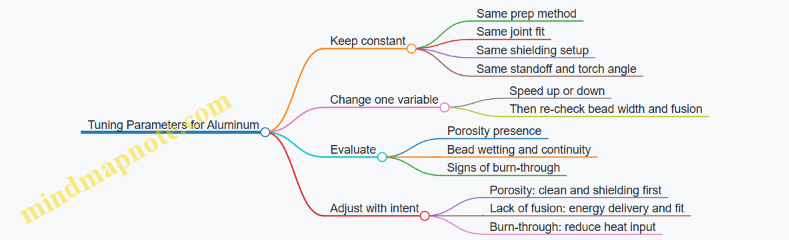
8.4 Welding Dissimilar Metals with Joint Preparation and Parameter Control
Dissimilar metal welding is less about “finding the one magic setting” and more about controlling three things: how the joint is prepared, how the heat is delivered, and how the weld pool solidifies. With handheld laser welding, the small spot and fast travel can be an advantage, but only if you keep the joint clean, the fit consistent, and the parameters matched to the weaker side.
Core Principle: Choose the Limiting Material First
Start by identifying which metal is more sensitive to cracking, oxidation, or excessive dilution. For example, when welding stainless to mild steel, the stainless side often dictates shielding needs and surface cleanliness, while the mild steel side dictates how much dilution you can tolerate without turning the weld chemistry into a mixed bag. A practical rule: set parameters to avoid overheating the more sensitive metal, then verify penetration and bead shape on a test coupon.
Joint Preparation That Prevents Chemistry Surprises
Dissimilar joints fail in predictable ways: contamination, poor fit, and uneven gap. Laser welding is precise, but it cannot fix a dirty interface.
- Clean both sides to the same standard. Degrease, then remove oxide where relevant. Stainless and aluminum oxide layers are stubborn; if you skip them, you often get porosity or weak fusion.
- Control the gap. A small gap can help wetting, but a large or uneven gap forces the laser to chase the joint. That increases dilution and can create lack of fusion on one side.
- Use joint geometry that supports consistent standoff. If one side sits higher, your standoff changes across the weld line, which changes power density.
- Plan for dissimilar expansion. Even when the laser input is low, thin sections can warp. Use clamps and tack points that lock alignment without crushing thin sheet.
Parameter Control: Match Heat Input to Joint Behavior
Think in terms of heat input, penetration balance, and dilution.
- Power and speed: Higher power or slower speed increases penetration and dilution. For dissimilar metals, that can be good on the “thicker or easier” side but harmful on the “sensitive” side.
- Focus and standoff: A slight focus shift changes keyhole behavior and bead width. Keep standoff consistent across the entire joint.
- Shielding gas: Use shielding to reduce oxidation at the weld pool surface. For aluminum and stainless, gas coverage often matters more than you expect.
- Travel path: A straight stringer can be enough for narrow joints, but if the joint is wider or the fit is imperfect, controlled overlap helps maintain fusion.
Example: Stainless to Mild Steel Lap Joint
Goal: achieve fusion into both metals without excessive dilution that weakens the stainless side.
Preparation: Clean both surfaces, ensure tight overlap, and remove any oxide on the stainless. Use a lap joint with a consistent overlap width so the laser sees a stable geometry.
Setup: Start with a conservative power and a speed that produces a stable bead without excessive penetration. Verify that the bead wets both edges and that the stainless side shows consistent fusion rather than a thin, shiny “skate” layer.
Adjustment logic:
- If you see lack of fusion on the mild steel side, slightly increase power or reduce speed while watching the stainless side for signs of overheating.
- If you see excessive penetration into the mild steel with a narrow or irregular stainless fusion zone, increase speed slightly or reduce power to lower dilution.
Example: Aluminum to Steel Edge Joint
Aluminum-steel joints are unforgiving because oxide layers and intermetallic formation can dominate failure modes.
Preparation: Remove aluminum oxide mechanically and/or chemically as appropriate for your shop process, then keep the time between cleaning and welding short. Ensure steel surface is free of oil and rust.
Setup: Use shielding and keep standoff consistent. Begin with parameters that produce full fusion on the steel side without blowing through thin aluminum.
Adjustment logic:
- If the bead looks like it sits on top of aluminum, increase wetting by improving surface condition first, then adjust speed and power modestly.
- If you get porosity, revisit shielding coverage and surface cleanliness before chasing parameter changes.
Mind Map: Dissimilar Metal Welding Workflow
Practical Verification: What to Inspect After the First Weld
Do not judge dissimilar welds only by surface appearance. After the first test coupon, inspect:
- Bead wetting on both sides: Both edges should show fusion, not just a surface smear.
- Penetration distribution: If one side is under-penetrated, the joint will fail under load even if the surface looks fine.
- Porosity and surface oxidation: Porosity often points to shielding or contamination; oxidation can indicate insufficient gas coverage or poor surface prep.
- Distortion: If the joint shifts during welding, your standoff and fit will drift on the next pass.
Case Logic: One Variable at a Time
When tuning, change only one parameter category per test. For example, if you suspect lack of fusion on the steel side, adjust power or speed slightly while keeping shielding and standoff unchanged. This keeps cause-and-effect readable, which is especially important when two metals behave differently under the same heat.
8.5 Repair Welding for Cracks Holes and Worn Surfaces
Repair work is where handheld laser welding earns its keep: you can localize heat, keep distortion low, and rebuild small damaged areas without turning the whole part into a heat-treated pretzel. The workflow is the same whether you’re chasing a crack, filling a hole, or rebuilding worn material—just with different emphasis.
Repair Planning and Part Assessment
Start by deciding what “good” looks like. For cracks, good means stopping the crack from growing and restoring load paths. For holes, good means restoring thickness and sealing. For worn surfaces, good means returning geometry and surface function.
- Identify the damage type and likely cause
- Cracks often start at stress concentrators: sharp corners, weld toes, threaded holes, or impact points.
- Holes usually come from corrosion, fatigue through-thinning, or mechanical damage.
- Worn surfaces come from abrasion, sliding contact, or misalignment.
-
Check material and thickness Laser parameters depend heavily on thickness and alloy. If you can’t confirm the alloy, treat the job as “unknown” and start with conservative test coupons from the same stock.
-
Decide whether to remove material first
- Cracks: you typically need to open the crack so the laser can fuse cleanly.
- Holes: you may need to bevel edges for full penetration.
- Worn surfaces: you often remove the damaged layer to create a stable base.
Crack Repairs with Controlled Stop Holes and Clean Edges
Cracks are sneaky because the laser can melt the surface while leaving the crack path unfused underneath. The fix is mechanical access plus laser fusion.
Step-by-step best practice
- Stop the crack by drilling a small hole at the crack tip. This reduces stress concentration and gives the laser a defined boundary.
- Open the crack with a narrow groove using grinding or a small end mill. Aim for clean, bright metal at the groove walls.
- Pre-fit if the crack is wide. Even a small gap can help you see fusion, but too much gap causes lack of fusion.
- Weld in short segments. Use overlapping passes so each segment remelts the previous one slightly.
Easy example A cracked mild-steel bracket at a weld toe: drill a 2–3 mm stop hole, grind a shallow V-groove, then run 3–5 mm long weld segments with consistent standoff. After cooling, inspect the groove for continuous fusion lines. If you see a “line” that doesn’t connect, reduce travel speed slightly and ensure the groove walls are clean.
Hole Filling with Edge Beveling and Heat Control
A hole repair is basically “make a new wall.” The laser must fuse to the perimeter, not just sit on top.
Step-by-step best practice
- Bevel the hole edges so the laser can reach the base. For thin sheet, use a shallow bevel to avoid burn-through.
- Support the back side if possible. Backing blocks reduce sag and help you maintain bead shape.
- Fill in layers. Start with a thin first layer that wets the bevel, then build thickness.
- Avoid chasing the crater. If the pool gets too deep, pause and let heat dissipate, then continue with smaller segments.
Easy example A 3 mm hole in stainless enclosure sheet: bevel to roughly a 30–45° edge, tack around the perimeter first, then fill with overlapping passes. After grinding flush, check for pinholes by visual inspection under strong light and by running a light bead test if the part must be sealed.
Rebuilding Worn Surfaces with Material Removal and Layered Build-Up
Worn surfaces fail because the surface layer is gone, not because the whole part is broken. Your job is to restore the worn profile without creating a weak boundary.
Step-by-step best practice
- Remove to sound metal. Grind until you stop seeing pitting, grooves, or smeared material.
- Create a shallow recess that matches the intended build thickness. This prevents the weld from forming a tall mound that’s hard to grind.
- Build in layers with controlled overlap. Each layer should slightly remelt the previous one.
- Finish with machining or grinding. Laser beads are great at building; they’re not always great at final dimensions.
Easy example A worn steel sliding pad: grind a shallow pocket, then deposit overlapping passes until you’re about 0.5–1.0 mm above final thickness. After cooling, grind to dimension and check flatness with a straightedge.
Mind Map: Repair Welding Decision Flow
Inspection and Corrective Actions That Actually Fix Things
Inspection should happen in stages.
- Before welding: verify groove cleanliness and fit. If you can’t remove oxides and contamination, the laser will weld the dirt, not the metal.
- After welding but before final grinding: look for incomplete wetting along edges, which often signals lack of fusion.
- After grinding: check for pinholes, surface cracks, or undercut at the perimeter.
Corrective actions
- Lack of fusion at edges: slow down slightly, ensure the torch angle keeps the beam aimed into the joint, and confirm the bevel/groove exposes clean metal.
- Burn-through or excessive penetration: reduce energy per pass by increasing travel speed or decreasing power, and switch to shorter segments with more cooling time.
- Porosity: improve surface cleaning and shielding coverage. If you’re using shielding gas, confirm flow and that the nozzle is positioned consistently.
Practical Parameter Notes for Repairs
Repairs benefit from repeatable technique more than heroic settings. Keep standoff consistent, use short segments, and overlap intentionally. When you change one variable, change only one—then you’ll know whether the fix worked or you just moved the problem to a different spot.
9. Quality Assurance and Inspection Methods
9.1 Visual Inspection Criteria Including Surface Continuity and Profile
Visual inspection is the fastest quality check you can do without cutting the part open. For handheld laser welds, it focuses on two things: surface continuity (is the weld path unbroken and properly sealed?) and profile (does the bead shape match what the process is capable of for that material and thickness?). If you treat these as separate checks, you’ll catch most issues before they turn into rework.
Surface Continuity Checks That Catch Real Problems
Start by confirming the weld is continuous along the intended path. A “continuous” weld is not just “there is metal.” It means the bead shows no interruptions that would allow leakage or rapid corrosion.
What to look for
- Unbroken bead line: The weld should follow the joint with no gaps, missing spots, or sudden stops.
- No pinholes on the surface: Small dots can indicate porosity or inconsistent shielding coverage.
- No undercut along edges: A groove beside the bead can reduce effective throat and create a stress riser.
- No obvious overlap failure: Where you expect overlap between passes or segments, the surface should not show a “step” that leaves a thin, weak boundary.
Easy example
- You weld a 1.5 mm mild steel lap joint. After cooling, you run a fingertip lightly across the bead. If you feel a series of tiny dips or see scattered pinhole-like dots, the weld may have trapped gas or inconsistent surface wetting. Even if the bead looks “mostly there,” those surface features are continuity failures.
Quick rule of thumb
- If the weld surface would let liquid run through a visible gap, it’s not a cosmetic issue.
Profile Checks That Confirm Process Stability
Profile is the bead’s geometry: width, height, reinforcement shape, and how smoothly it transitions into the base metal. Laser weld profiles are sensitive to standoff, travel speed, and joint fit, so profile tells you whether the torch behavior matched the setup.
What to look for
- Bead width consistency: Wide-to-narrow swings often mean speed or standoff drift.
- Reinforcement shape: A smooth crown with gradual edges is typical. Sharp peaks can indicate too much energy per unit length.
- Edge blending: The bead should merge into the base metal without a harsh boundary.
- Penetration clues from surface: While you can’t measure penetration visually with certainty, a bead that is too narrow for the joint and thickness often correlates with lack of fusion.
Easy example
- On stainless sheet, you set parameters for a clean, narrow bead. If subsequent welds show a noticeably broader bead and a flatter crown, it can indicate torch angle drift or standoff variation. The weld may still be continuous, but the profile shift suggests the process is no longer operating in the intended window.
Using Lighting, Angle, and Cleanliness Like a Pro (Without Being One)
Visual inspection is only as good as the viewing conditions. Use consistent lighting and viewing angles so you’re comparing welds to welds, not welds to whatever the shop lights feel like today.
- Lighting: Bright, directional light helps reveal undercut and pinholes.
- Viewing angle: Look from the side to judge edge blending and from above to judge continuity.
- Surface cleanliness: Remove spatter and loose oxide before judging. Spatter can hide small defects; oxide can mimic a rough profile.
Practical example
- After welding, you wipe the bead with a clean cloth and remove loose spatter. If a “smooth” weld suddenly reveals a line of tiny discontinuities, you were previously inspecting debris, not the weld.
Mind Map: Visual Inspection Criteria for Laser Welds
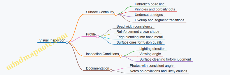
Systematic Workflow for Each Weld
- Confirm the weld path: Compare the bead to the intended joint line. If the bead wandered, profile and continuity may both be compromised.
- Check continuity first: Look for gaps, pinholes, and undercut before judging bead shape.
- Then check profile: Evaluate width, crown smoothness, and blending at both edges.
- Compare to your baseline: Use earlier “good” welds from the same material and thickness as your reference, not memory.
- Record what you see: Note whether the issue is continuity-related (gaps, pinholes) or profile-related (width drift, sharp crown). This distinction speeds up troubleshooting.
Example workflow
- A weld shows continuity (no gaps), but the bead is wider than your baseline and the edges look less blended. You log it as a profile deviation. That points you toward standoff, torch angle, and travel speed rather than gas coverage alone.
Common Visual Findings and What They Usually Mean
- Pinholes with otherwise continuous bead: Often points to shielding coverage problems or surface contamination.
- Undercut with a smooth crown: Often points to energy distribution and edge wetting balance.
- Narrow bead with poor edge blending: Often correlates with insufficient fusion at the edges or joint fit issues.
- Width variation along the weld: Often correlates with inconsistent travel speed or standoff.
The goal isn’t to guess perfectly from a photo. The goal is to classify the defect correctly from the surface so the next check—mechanical, dimensional, or cross-section—targets the right cause.
9.2 Measuring Weld Size Including Bead Width and Penetration Indicators
Measuring weld size is how you turn “it looks good” into “it will pass again tomorrow.” For handheld laser welding, the two most practical indicators are bead width (what you can see on the surface) and penetration (what you infer from cross-section or reliable proxies). You’ll get the best results when you measure the same way every time: same lighting, same part orientation, same measurement location, and the same documentation format.
Core Concepts You Measure First
Bead width is the surface footprint of the weld pool. It reflects how the laser spot, travel speed, and standoff work together. If bead width grows while penetration stays flat, you’re often spreading heat without driving it deeper.
Penetration is the depth of fusion into the base metal. It’s the main driver for joint strength, especially in butt joints and thin-to-thick transitions. Surface width alone can’t guarantee penetration because a wide, shallow weld can still fail under load.
Bead Width Measurement Method
- Prepare the surface consistently. Remove oxide, oil, and heavy spatter. A quick wipe and light cleaning is usually enough for repeatable measurements.
- Choose a measurement rule. Measure the maximum bead width across the weld centerline, not the widest random spot.
- Use a stable reference. Mark the weld centerline with a fine marker before measuring. Then measure perpendicular to the centerline.
- Measure at multiple points. For a 50 mm weld, measure at 3 locations: start, middle, end. Record each value and the range.
A simple example: you weld 1.5 mm mild steel with the same parameters for three passes. You measure widths of 1.8 mm, 2.1 mm, and 1.9 mm. That range tells you your hand motion and standoff consistency are reasonably stable. If you see 1.2 mm at the start and 2.3 mm at the end, your torch path or start/stop technique is changing.
Penetration Indicators That Actually Help
True penetration measurement requires a cross-section, but you can still use indicators that correlate with penetration.
Best direct method
- Cut a small section through the weld, polish, and inspect the fusion zone. Measure penetration depth from the top surface to the deepest fusion point.
Practical proxy indicators
- Bead profile shape: A narrow, high crown often suggests deeper fusion, while a flat, wide bead can indicate shallow fusion.
- Undercut and toe geometry: Excessive undercut can accompany high energy or poor torch angle; it may look “aggressive” but doesn’t automatically mean good penetration.
- Backside fusion visibility: For thin sheet or through-welds, you may see a faint change in the backside appearance. Treat this as a screening tool, not a final measurement.
Concrete example: on 2 mm stainless, you observe a bead width increase of about 0.4 mm after slowing travel speed. If the cross-section later shows penetration rising from 0.9 mm to 1.2 mm, your width increase was a good sign. If penetration stays at 0.9 mm, you learned that width was driven by spreading rather than depth.
Mind Map: What to Measure and Why
Turning Measurements into Parameter Decisions
Use measurements to decide what to adjust, not just to report numbers.
- If bead width is too small and penetration is also low: increase energy delivery (commonly by reducing travel speed or increasing power within your safe limits) and verify standoff.
- If bead width is too large but penetration is shallow: reduce energy spreading. Typical fixes include increasing travel speed slightly, improving joint fit, and checking standoff consistency.
- If width varies along the weld: focus on torch steadiness and start/stop technique. A consistent torch path usually tightens the width range before you chase parameter changes.
Quick Measurement Checklist
- Cleaned surface with consistent prep
- Marked centerline for perpendicular width measurement
- Width recorded at start, middle, end
- Penetration confirmed by cross-section at least during setup trials
- Proxy indicators used only after you’ve established correlation for that material and thickness
When you measure this way, bead width becomes a reliable surface story, and penetration becomes a grounded depth story. Together, they tell you whether your handheld technique is producing welds that are not only visible, but also structurally meaningful.
9.3 Simple Mechanical Checks Including Bend and Peel Tests
Visual inspection tells you what the weld looks like. Mechanical checks tell you what it can survive. For small workshops, bend and peel tests are fast, low-cost ways to catch weak fusion, poor wetting, and brittle behavior before a part goes into service.
What You Are Actually Testing
A bend test checks whether the weld metal and the heat-affected zone can deform together without cracking. A peel test checks whether the weld bond can resist separation under a controlled opening force. Both tests are most useful when you compare results across parameter changes, not when you treat a single pass as “good forever.”
Preparing Test Coupons
Use the same material, thickness, joint type, and cleaning steps as the real job. Cut coupons large enough to clamp comfortably and to leave room for the bend radius or peel grip. Mark the weld centerline and the side that faces the bend or peel load so you can interpret cracks consistently.
A practical rule: if your real part will be welded in multiple passes, test coupons should include the same pass pattern. Otherwise, you might “pass” a coupon that never had to deal with the same thermal history.
Bend Test Fundamentals
Choose a bend method that matches your workshop tools:
- Mandrel bend uses a fixed radius and a controlled wrap.
- V-block bend uses two supports and a press or lever to create a single bend.
Start with a moderate bend angle and increase only if the coupon survives. Excessive bending can create cracks that are not caused by the weld quality but by unrealistic strain.
How to run a simple V-block bend
- Place the coupon on two supports with the weld centered over the gap.
- Apply force gradually until the coupon reaches the target angle.
- Inspect the weld face and the opposite side for cracks, lack of fusion openings, or tears.
What to look for
- Cracks at the weld toe often indicate poor fusion at the edge.
- Cracks along the weld centerline can indicate weak weld metal or excessive brittleness.
- Open seams that appear before the final bend suggest lack of fusion or insufficient wetting.
Peel Test Fundamentals
Peel testing is especially handy for lap joints and thin sheet where bending can be awkward. The goal is to force the weld to separate in a way that reveals weak bonding.
How to run a simple peel test
- Weld two overlapping strips with the same overlap length you use in production.
- After cooling, clamp one strip firmly.
- Pull the other strip to open the joint at a steady rate.
- Observe where separation occurs: in the weld, at the interface, or in the base metal.
How to interpret results
- Separation through base metal usually indicates the weld bond is stronger than the surrounding material.
- Separation along the weld interface points to lack of fusion or insufficient penetration.
- Separation with a jagged, crumbly weld face can indicate brittle behavior or contamination that weakened the bond.
Mind Map: Mechanical Checks Workflow
Example: Diagnosing a Weak Weld with One Coupon Set
Suppose you weld mild steel lap joints and the part sometimes fails during handling. You run two coupons with different travel speed settings.
- Coupon A shows a clean bend with no visible cracks on the weld face.
- Coupon B shows a crack starting at the weld toe.
Because the crack location is consistent, you can focus on edge fusion rather than general weld strength. You then adjust technique or parameters that affect wetting at the toe, such as maintaining stable standoff and ensuring the beam tracks the joint edges.
Example: Peel Test Tells You Where the Problem Lives
You weld stainless sheet lap joints. In the peel test, one coupon separates along the weld interface with a smooth line.
That failure mode is a strong hint that the bond never fully connected across the overlap. If you also see shallow penetration in visual inspection, the combined evidence points to insufficient energy delivery or poor fit-up, not just surface appearance.
Recording Results Without Making It Complicated
For each coupon, note: material, thickness, joint type, parameter set, test type, target bend angle or peel distance, and the failure location (toe, centerline, interface, or base metal). This turns “it feels weak” into a repeatable diagnosis you can act on the next day.
9.4 Cleaning and Passivation Checks for Stainless Welds
Stainless weld quality is not just about getting a neat bead. The weld zone must also keep enough corrosion resistance, which depends on how you clean before welding and how you remove heat-tint and contamination after welding. Laser welding can reduce heat input, but it does not magically fix dirty surfaces or missed oxide removal.
Why Cleaning Matters for Corrosion Resistance
Stainless steel relies on a thin chromium-rich oxide layer. Welding disrupts that layer in two ways: it heats the surface and it can introduce contaminants such as oils, marker ink, or carbon steel dust. Heat tint and embedded iron particles can locally reduce corrosion resistance, even if the weld looks solid.
Foundational Cleaning Workflow
Start with a repeatable sequence so every part gets the same treatment.
- Pre-weld degreasing: Wipe with a dedicated stainless-safe cleaner or solvent, then use clean lint-free wipes. If you can smell the cleaner strongly, you likely left residue—wipe again with fresh material.
- Mechanical cleaning to bright metal: For areas that will be welded and a small margin around the joint, remove oxide and surface contamination. Use stainless-dedicated brushes or abrasive pads.
- Segregate tools: Never use the same brush for carbon steel and stainless. If you do, you can drag iron contamination into the weld zone.
- Post-weld heat tint removal: After welding, remove discoloration and any surface iron. This is where many “it passed visually” parts fail later.
Passivation Checks That Actually Mean Something
Passivation is not a single magic step; it’s a controlled chemical process that supports the oxide layer. Your checks should confirm both cleanliness and surface condition.
Visual and Surface Condition Checks
- Heat tint coverage: Look for straw, blue, or purple discoloration around the weld. Any remaining tint in the cleaned zone is a sign the surface still needs treatment.
- Iron contamination spotting: If you see tiny dark specks or rough patches that feel gritty, treat them as embedded contamination until proven otherwise.
- Wipe test: After cleaning, wipe with a clean white cloth. If you get dark streaking, you still have loose residue.
Chemical and Process Checks
- Passivation solution control: Confirm concentration and temperature match the process instructions for your chemistry. Too weak under-treats; too strong can be harsh on surfaces.
- Rinse completeness: After passivation, rinse thoroughly. Residual chemicals can leave spots and can interfere with the oxide layer.
- Drying method: Dry with clean air or lint-free wipes. Water spots can mimic corrosion initiation and complicate inspection.
Mind Map: Cleaning and Passivation Checks for Stainless Welds
Example: Enclosure Seam That Looks Fine but Fails Inspection
A common scenario: a stainless enclosure seam is welded, then only wiped down. The weld bead looks uniform, but the area around it still shows faint heat tint. During inspection, the surface shows early staining in the heat-affected zone.
Corrective approach: Re-clean the weld area mechanically to remove remaining discoloration, then repeat passivation with controlled concentration and temperature. After passivation, perform a wipe test and confirm the weld zone is free of tint before releasing the part.
Example: Brushed Stainless That Still Shows Iron Specks
Another scenario: the shop uses a wire brush that “has been used for years.” Even if it’s mostly used on stainless, it may have picked up carbon steel dust.
Corrective approach: Replace or dedicate the brush and abrasives for stainless only. Re-clean the weld area, then passivate again. The key check is the wipe test after post-weld cleaning—if you still see dark transfer, you haven’t removed the contamination yet.
Practical Inspection Criteria You Can Use Immediately
- No visible heat tint in the defined inspection zone around the weld.
- No dark residue on a clean white wipe after final rinse and drying.
- Consistent process records for passivation concentration, temperature, and rinse steps so the same part type gets the same treatment.
When these checks are treated as part of the welding procedure rather than an afterthought, stainless welds stop being a “looks good today” problem and become a “stays good” process.
9.5 Keeping Weld Records for Repeatability and Traceability
Good weld records do two jobs: they help you reproduce a successful result, and they explain what happened when something doesn’t match the plan. In a small workshop, the goal isn’t paperwork for its own sake; it’s making the next setup faster and the next investigation calmer.
What to Record Every Time
Start with a consistent minimum set. If you only capture a few items, capture the ones that directly change the weld pool.
- Part identity: job name, customer or internal batch ID, material grade, and thickness.
- Joint details: joint type, gap/fit-up notes, and any edge prep method (for example, brushed, ground, or solvent cleaned).
- Setup conditions: torch model, nozzle or lens protection used, stand-off distance, and shielding gas type and flow.
- Process parameters: laser power setting, travel speed, focus position, and any pulsing or mode selection if your system uses it.
- Consumables and handling: filler wire used or not, wire diameter, and whether parts were clamped or tack welded.
- Operator and date: operator name or initials and the date of the weld trial or production run.
- Outcome: visual notes, pass/fail against your inspection criteria, and any rework performed.
A practical rule: if you would change it between two welds, it belongs in the record.
A Simple Record Template That Actually Gets Used
Keep the template short enough to fill out during the job. Use checkboxes and short fields rather than essays.
Example record entry
- Job: Frame bracket batch B-17
- Material: Mild steel, 2.0 mm
- Joint: Lap, 10 mm overlap
- Fit-up: 0.2 mm gap max
- Prep: Ground to bright metal, wiped with solvent
- Torch: Handheld model X, nozzle Y
- Stand-off: 6.0 mm measured with gauge
- Focus: Set to marked focal position
- Shielding: Argon, 8 L/min
- Parameters: Power 1.2 kW, speed 0.35 m/min
- Filler: None
- Clamping: Two clamps, tack at both ends
- Result: No undercut, uniform bead, passed bend test
- Notes: Slight spatter at start; improved after 2 mm ramp-in
That last line matters because it tells you what to do next time without guessing.
Mind Map: Weld Record Structure
Weld Records Mind Map
Linking Records to Inspection Criteria
Records become useful when they connect to what you inspected. If your acceptance criteria include bead width, penetration appearance, and absence of porosity, write down the observations in the same language each time.
- Visual: “No visible lack of fusion at toe,” “uniform bead with consistent wetting,” or “porosity visible as pinholes.”
- Measurements: bead width range, any thickness loss, and whether the weld shows full fusion at the joint edge.
- Mechanical checks: bend direction, bend angle achieved, and where failure occurred if it did.
If you only record “passed,” you lose the ability to explain why it passed.
Change Control Without Bureaucracy
Small workshops still need a way to track changes. Treat any adjustment as a deliberate event.
- When you change stand-off, focus, gas flow, or power/speed, record the reason and the effect.
- If you adjust parameters after a defect, note the defect type and the corrective action.
Example change note
- “Porosity observed at start; increased gas flow from 6 to 8 L/min and extended pre-flow by 1 second. Result: porosity eliminated.”
This turns troubleshooting into a reusable procedure.
Storage and Versioning That Prevents Lost Context
A record is only as good as the ability to find it later.
- Use a consistent folder naming scheme: JobID_Material_Thickness_Date.
- Store trial weld results separately from production entries.
- If you revise parameters, create a new version entry rather than overwriting the old one.
Example naming
B-17_MildSteel_2.0mm_2026-02-15_Trial1B-17_MildSteel_2.0mm_2026-02-15_ProductionA
(Using a fixed date format avoids confusion when files are shared.)
Common Failure Modes to Avoid
- Missing fit-up notes: a perfect parameter set can still fail with poor gap control.
- No stand-off or focus confirmation: handheld work is sensitive to distance and focal position.
- Outcome without defect description: “bad weld” doesn’t tell you what to fix.
- Overwriting trial data: keep the baseline so you can compare improvements.
A good record doesn’t just document what you did; it preserves the reasoning behind it so the next weld doesn’t require a fresh guess.
10. Defect Diagnosis and Corrective Actions
10.1 Porosity Including Gas Coverage and Surface Contamination Causes
Porosity in handheld laser welds shows up as small voids trapped in the weld metal. It usually forms when shielding is insufficient or when the surface releases gases faster than the molten pool can expel them. The trick is to treat porosity like a system problem: gas delivery, surface condition, and process settings all interact.
What Porosity Looks Like and Why It Matters
Porosity can be scattered pinholes or clustered voids. Even when the bead looks smooth, voids reduce effective cross-section and can become crack starters under vibration or thermal cycling. In thin sheet, porosity also changes how the weld conducts heat, which can worsen consistency from pass to pass.
Gas Coverage Fundamentals
Shielding gas protects the molten pool from oxygen and nitrogen in the air. If the gas coverage is patchy, the pool surface oxidizes and becomes less able to release dissolved gases. That oxidation can also change wetting, making it easier for bubbles to get trapped.
Common gas-related causes include:
- Low flow rate: The torch plume can’t displace air around the pool.
- Wrong gas type: Some gases protect better for certain metals and setups.
- Incorrect standoff distance: Too far spreads the gas; too close can disturb flow.
- Torch angle drift: If the torch points away from the weld direction, the gas blanket shifts.
- Drafts and airflow: Fans, open doors, and cross-breezes steal shielding.
A practical way to think about it: the gas blanket is like a temporary bubble around the weld. If the bubble is thin, the pool “breathes” air.
Surface Contamination Fundamentals
Even with perfect gas, contamination can generate gas at the wrong time. The molten pool can’t always wait for contaminants to burn off before it solidifies.
Typical contamination sources:
- Oil and cutting fluids: They vaporize and leave bubbles.
- Paint, coating, or plating: They decompose into gases and sometimes slag-like residues.
- Rust and oxide layers: They introduce oxygen and can promote unstable wetting.
- Moisture: Fingerprints, damp rags, and wet storage can create localized gas pockets.
Laser welding is less forgiving than many people expect because the process concentrates energy into a small region. That means contaminants have less time to escape before the pool freezes.
How Gas and Contamination Combine
Porosity often comes from the overlap of two issues. For example, a slightly low gas flow might be tolerable on a clean surface, but the same setup will struggle on oily steel. Conversely, a clean surface can still show porosity if the gas blanket is disrupted by drafts or incorrect standoff.
Mind Map: Porosity Causes and Checks
Systematic Troubleshooting Workflow
- Confirm the pattern: Pinholes spread evenly often point to shielding or general contamination. Clustered voids near edges can indicate joint fit gaps or localized contamination.
- Control airflow: Close doors, pause fans, and weld in a consistent spot. If porosity improves, shielding was the main limiter.
- Verify standoff and torch angle: Use a simple reference mark on the torch body or a fixture that keeps distance consistent.
- Clean the surface the same way every time: Degrease, then remove oxide or coating where applicable. If you can’t remove it fully, at least standardize the method so results are repeatable.
- Run a clean scrap test: Weld a short bead on the same material batch. If scrap is clean and porosity disappears, the problem is likely surface condition or local setup.
- Adjust one variable at a time: Increase gas flow in small steps, or correct standoff, then re-test. Jumping multiple settings at once makes it impossible to learn.
Example: Mild Steel Bracket with Pinholes
A small bracket shows pinholes across the bead. The operator notices the torch is held slightly farther than usual because the part geometry forces a different hand position. After standardizing standoff with a simple spacer block and welding with the same parameters, porosity reduces significantly. A second pass after degreasing the bracket with a consistent solvent method removes the remaining pinholes.
Example: Stainless Sheet with Edge Clusters
A stainless enclosure panel has voids concentrated near the edges of the lap joint. The surface near the edges was handled more often and had visible fingerprints. Cleaning both faces with the same degreasing method reduces edge porosity, but a few voids remain until the joint fit is improved so there are fewer micro-gaps. The lesson: edge clusters often reflect localized contamination plus trapped space.
Advanced Detail: Reading the Weld Pool Behavior
When shielding is weak, the bead can look slightly dull or uneven, and the pool may appear less stable. When contamination is the issue, you may see intermittent bubbling during the pass, followed by voids that “freeze in.” Joint gaps can mimic contamination symptoms by providing a place for gas to collect before solidification.
The goal is not just fewer pores, but predictable pores. Once you can reproduce a clean bead on scrap and on the actual part using the same cleaning and gas setup, you’ve solved the underlying cause rather than chasing symptoms.
10.2 Lack of Fusion Including Travel Speed and Joint Fit Issues
Lack of fusion means the weld pool did not fully connect to the base metal along the joint surfaces. In handheld laser welding, it often shows up as a weak bond line, a narrow or irregular penetration profile, or a bead that looks fine on top but fails simple mechanical checks. The two most common causes are travel speed that is too fast and joint fit that leaves gaps or inconsistent contact.
Foundational Mechanism: Why Fusion Fails
Laser welding relies on energy density at the joint to melt both the weld pool and the adjacent base metal. If the laser spends too little time over a location, the pool may form but not reach the sidewalls. If the joint fit is poor, the laser energy may be absorbed by edges that are not aligned, or the pool may bridge across a gap without wetting the surfaces.
A practical way to think about it: fusion needs both time and contact. Speed controls time. Joint fit controls where the melted metal can actually flow and wet.
Travel Speed Too Fast
When travel speed increases, the heat input per unit length drops. The result is typically reduced penetration and incomplete sidewall wetting. On thin material, the bead may still look continuous, which is why this defect can sneak past quick visual checks.
Easy diagnostic: Make a short test weld at a moderate speed, then repeat at a faster speed with the same focus and standoff. Cut the samples and inspect the cross-section. The faster weld will usually show a shallower fusion zone and a clearer boundary between weld metal and base metal.
Corrective actions:
- Slow down in small steps and keep focus and standoff unchanged.
- If your machine uses a power setting that is fixed for the test, treat speed as the primary lever.
- Watch for the opposite problem: if you slow too much, you may increase penetration beyond what the joint can tolerate, leading to burn through or excessive reinforcement.
Concrete example: Welding a 2 mm mild steel lap joint. At a higher travel speed, the weld bead appears smooth, but a peel test separates along the joint line. After slowing the travel speed by a noticeable step while keeping the same torch angle, the peel test shows failure in the base metal rather than along the interface.
Joint Fit Issues Including Gaps and Misalignment
Even with correct speed, lack of fusion can occur if the joint geometry prevents the pool from wetting the intended surfaces.
Common fit problems include:
- Gaps between parts, especially in lap joints where the laser must bridge.
- Step misalignment where one edge sits higher, causing the pool to favor one side.
- Inconsistent edge contact along the seam due to poor clamping or warped parts.
Easy diagnostic: Run a straight seam and mark the areas where the parts are closest and farthest. If fusion is consistently worse where the gap is largest, joint fit is the culprit.
Corrective actions:
- Clamp to eliminate movement during welding.
- Use simple spacers or temporary tack points to maintain consistent gap.
- For lap joints, ensure the overlap surfaces are clean and seated flat.
- If you must weld over a small gap, reduce speed slightly so the pool has time to wet both sides, but do not treat this as a substitute for fit.
Concrete example: Welding a stainless enclosure corner with a small but uneven gap. The weld looks acceptable on the tight side, but the loose side shows a visible lack of bonding after grinding. Re-fixturing to remove the gap and repeating the weld at the original speed produces a uniform fusion line.
Interaction Between Speed and Fit
Speed and fit are not independent. A seam with a small gap can sometimes be welded successfully at a slower speed because the pool has more time to flow and wet. However, if the gap is large or the edges are misaligned, slowing down may only increase the chance of defects like excessive penetration or distortion.
A good workflow is to fix fit first, then tune speed. If you tune speed while the joint is inconsistent, you may end up with a weld that passes in one region and fails in another.
Mind Map: Lack of Fusion Root Causes and Fixes
Quick Field Checklist
Before changing parameters, verify the basics: the seam is clamped so the gap is consistent, the edges are seated flat, and the torch height and focus are stable. Then adjust travel speed in controlled steps and confirm with a cut or a simple mechanical test. If the defect tracks with the seam geometry, treat joint fit as the primary variable; if it tracks with the weld length regardless of geometry, treat travel speed as the primary variable.
10.3 Excess Penetration and Burn Through Including Parameter Adjustments
Excess penetration means the weld goes deeper than intended, often thinning or blowing through the far side on thin sheet. Burn through is the extreme version: the beam energy and dwell time combine with poor heat sinking or joint fit so the material can’t stay intact. The fix is usually not one magic knob; it’s a chain of adjustments that reduce effective energy delivered to the joint while keeping the weld pool stable.
Start with What You See
Look at three clues before changing anything:
- Far-side condition: a clean hole suggests burn through; a dark, thin spot suggests near-burn-through.
- Bead width vs. depth: if width is normal but depth is excessive, you’re likely too focused or too slow.
- Edge condition: heavy undercut at the edges often points to excessive energy density or torch angle that lets the pool run away.
A quick workshop habit helps: make one change at a time on scrap from the same sheet batch. If you change speed, focus, and standoff together, you’ll only learn that the weld is different.
Mind Map: Causes and Adjustments
Parameter Adjustments That Actually Move the Needle
Travel Speed
Travel speed is the fastest lever to reduce penetration. If you’re burning through, increase speed first because it reduces dwell time without changing optics.
- Example: On 1.0 mm mild steel, if a baseline weld at 6 mm/s produces a near-hole, try 7–8 mm/s and re-test. If the bead becomes too narrow or shows lack of fusion, you overshot; step back by 0.5–1 mm/s.
Power
If speed alone doesn’t fix it, lower power in small steps. Power changes the energy available to form and sustain the keyhole or deep penetration mode.
- Example: Suppose your baseline is 900 W and you see burn through at the center of a seam. Reduce to 850 W, keep speed constant, and confirm penetration depth. If you still get holes, drop another 25–50 W.
Focus and Standoff
Excess penetration often comes from delivering energy too tightly at the work surface.
- Focus too tight: the beam waist sits where you don’t want it, increasing energy density.
- Standoff too small: the spot can become smaller and hotter at the joint.
Practical check: after any torch height adjustment, do a short test bead on scrap and compare bead width. A narrower, deeper bead after lowering standoff is a strong sign you’re concentrating too much.
- Example: If your spec standoff is 10 mm and you accidentally run at 6 mm, you may see burn through even with unchanged power and speed. Return to 10 mm, then fine-tune with speed.
Overlap and Dwell at Starts and Stops
Weaves and edge pauses add dwell time. On thin sheet, even a brief hesitation can tip the weld from “deep” to “gone.”
- Example: If you’re using a weave with 30–40% overlap, reduce overlap or switch to a straight stringer for thin sections. Also start the motion before the joint and finish after it.
Technique Adjustments That Prevent the Pool from Running Away
Torch angle affects how the molten pool wets and where heat concentrates. If the torch is angled so the beam “leans” into the joint root, penetration increases.
- Example: For a butt joint on thin sheet, if you’re holding the torch with a noticeable forward tilt, reduce the tilt toward perpendicular. Re-test with the same speed and power so you can attribute the change.
Joint Support and Fit Up
Even perfect parameters can fail if the joint is open or unsupported. A gap reduces heat conduction into the surrounding material and can let the beam concentrate at the thinnest path.
- Example: Two 1.0 mm plates with a 0.5 mm gap may burn through at the gap edges. Clamp tighter, or add a temporary backing strip to spread heat.
Quick Adjustment Workflow for Thin Sheet
- Return to correct standoff and focus.
- Increase travel speed by 15–30%.
- If still burning through, reduce power by 5–10%.
- If you’re weaving, reduce overlap or switch to stringer.
- Improve fit up and add backing support if needed.
Verification Criteria
After each change, confirm:
- Bead width is consistent with your target range.
- Penetration is deep enough for fusion but no longer thinning the far side.
- Edges show stable wetting without excessive undercut.
When the weld stops burning through, don’t keep chasing “more penetration.” In thin sheet, the goal is reliable fusion with controlled heat input—because the metal only gets one chance to stay in one piece.
10.4 Cracking Including Hydrogen and Thermal Stress Mitigation Steps
Cracking in laser welds usually comes from two interacting problems: hydrogen-driven cracking and thermal-stress cracking. Hydrogen is the “fuel,” while restraint and shrinkage are the “match.” Your job is to reduce both, using steps you can apply on a small-workshop schedule.
Foundational Concepts That Predict Cracking
Hydrogen cracking is most likely in steels that can form hard microstructures, especially when the weld cools fast. Fast cooling increases hardness and reduces ductility, so even small strains can open a crack. Thermal-stress cracking is more about how the part is held during welding: shrinkage pulls the joint together, and if the surrounding metal can’t move, stress concentrates at the weld toe or within the weld.
A practical way to think about it: if you can lower hydrogen and slow cooling just enough to keep hardness reasonable, you reduce the chance that stress will find a weak spot.
Hydrogen Sources You Can Control Immediately
Hydrogen enters from contamination and moisture. Common culprits include oily surfaces, wet coatings, damp shielding gas supply components, and residue from cutting or grinding.
Start with a simple rule: clean to bright metal where the weld will be. For mild steel, a wire brush dedicated to that material and a wipe with a solvent that leaves no residue works well. For stainless, avoid touching the area with tools that previously cleaned carbon steel.
If you use shielding gas, check flow and leaks. A small leak can pull in air and moisture, and that’s hydrogen’s favorite entrance ramp.
Thermal Stress Sources You Can Control Immediately
Thermal stress comes from restraint and geometry. Thin sections, long seams, and parts with tight fixturing are common troublemakers. Even when the weld looks fine, the surrounding metal can be locked in place, so shrinkage creates high strain.
Use fixturing that supports alignment but allows controlled movement. If you clamp rigidly across the seam, the part can’t relax as it cools, and cracks become more likely.
Step-by-Step Mitigation Workflow
- Choose a joint and fit-up that reduces restraint. Aim for consistent gap and good contact. A large gap forces extra melting and increases shrinkage.
- Clean and dry the weld zone. Remove oil, paint, and moisture. If parts have been stored in a damp area, dry them before welding.
- Set parameters to control cooling rate. Lower travel speed or slightly higher heat input can reduce hardness by slowing cooling. Don’t chase penetration at all costs; excessive heat can worsen distortion and still not fix hydrogen.
- Use a shielding strategy that stays stable. Verify gas flow before the first weld. Keep the nozzle clean and maintain consistent standoff.
- Sequence the weld to balance shrinkage. For longer seams, use intermittent welding or backstep patterns so the part doesn’t pull in one direction only.
- Allow stress relief through controlled restraint. Use tack welds to hold alignment, then weld in a way that lets the joint relax. If you must use strong clamps, place them farther from the weld line.
- Apply post-weld heat treatment when required. For higher-risk steels, a low-temperature stress relief can reduce hardness and help hydrogen diffuse out. The key is timing: heat treatment should occur soon enough after welding that hydrogen still has a path to escape.
How to Decide Whether You Need Heat Treatment
If you’re welding plain carbon or low-alloy steels, cracking risk rises when the weld region becomes hard. Signs include very fast cooling conditions, thick-to-thin transitions, and joints that are heavily restrained. Also, if you see delayed cracking—cracks appearing after the weld cools—hydrogen is a strong suspect.
A workshop-friendly decision method is to run a small test coupon with your real fit-up and fixturing. Inspect after cooling and again after a short waiting period. If cracks appear, treat the process as hydrogen-sensitive and add cleaning, parameter tuning, and post-weld heat treatment as needed.
Concrete Examples from Common Workshop Scenarios
Example: Mild Steel Bracket With Tight Clamps A bracket is clamped rigidly across the seam. The first weld looks smooth, but a crack appears near the toe. Fixes: clean to bright metal, reduce clamp pressure near the weld line, and weld in short segments with a balanced sequence. If cracking persists, add a low-temperature stress relief after welding.
Example: Wet-Coated Sheet Metal Repair A repair is attempted on a panel with residual moisture from storage. The weld shows porosity and later cracking at the edge. Fixes: dry the panel, remove coating and residue around the weld zone, and confirm shielding gas stability. Then re-weld with consistent standoff and a parameter set that avoids overly rapid cooling.
Mind Map: Hydrogen and Thermal Stress Cracking Mitigation
Quick Checklist Before You Weld
Clean the weld zone, confirm shielding stability, avoid rigid restraint across the seam, and use a weld sequence that balances shrinkage. If cracks appear after cooling or in high-risk joints, add parameter tuning for cooling control and use post-weld stress relief when your material and geometry require it.
10.5 Spatter and Surface Roughness Including Optics and Process Tuning
Spatter and roughness usually share the same root: the weld pool is being asked to behave while the energy delivery, shielding, and surface condition are not cooperating. Spatter looks like tiny droplets that land around the bead; roughness is what you feel when you run a fingertip over the weld profile. Treat them as symptoms, then tune the system in a logical order: optics first, then surface and shielding, then process parameters.
What Spatter Signals in a Laser Weld Pool
Spatter often appears when the pool is unstable or too shallow to “catch” the energy smoothly. Common triggers include:
- Too much energy density for the current travel speed, causing violent keyhole behavior.
- Inadequate shielding so the molten metal oxidizes and ejects more easily.
- Contaminated or uneven surface that changes absorption and creates local overheating.
- Focus or standoff error that shifts the peak intensity away from the intended spot.
A practical workshop check: make two short test welds on the same scrap, one with a slightly slower speed and one with a slightly higher speed. If spatter increases as speed slows, you likely have energy too high per unit length or focus too tight. If spatter increases as speed increases, you may be under-filling the joint and forcing the pool to “fight” for penetration.
How Roughness Forms and Why It Matters
Roughness comes from a bead that doesn’t solidify smoothly. That can happen when the pool is too narrow, too wide, or repeatedly disturbed. Roughness is also affected by:
- Keyhole instability leading to uneven penetration and surface ripples.
- Excessive overlap or oscillation that reheats the same track too many times.
- Inconsistent standoff that changes spot size and intensity.
If the weld is structurally sound but rough, you can often improve appearance by stabilizing technique and optics rather than chasing lower power alone.
Optics First Because It’s the Fastest Variable to Fix
Before changing parameters, verify optics condition and alignment. Dirty lenses scatter light and reduce effective power at the workpiece, which can cause the operator to compensate by increasing settings—often making spatter worse.
Quick optics routine
- Inspect the lens for smoke residue or pitting.
- Clean using the manufacturer’s method and avoid touching the active surface.
- Confirm the correct focus mode and that the torch height reference is being followed.
Workshop example: If spatter suddenly appears after a day of welding stainless, check the lens. Stainless fumes can leave a residue that’s easy to miss. After cleaning and re-checking standoff, you often return to the previous parameter set and the spatter disappears.
Mind Map: Spatter and Roughness Tuning Path
Process Tuning That Moves from Cause to Fix
Use small, controlled changes. A good pattern is to adjust one variable at a time while keeping the rest constant.
- Standoff and focus: If spatter is accompanied by a wider-than-expected bead and inconsistent penetration, suspect focus. Increase or decrease standoff in small steps to bring the spot back to the intended size.
- Power-to-speed balance: Reduce power slightly or increase speed slightly if spatter is heavy and the bead looks “boily.” If penetration is weak and the bead is rough, increase power slightly or slow down slightly, but only after optics and shielding are confirmed.
- Shielding coverage: If spatter is moderate but roughness is high and the weld surface looks dull or mottled, check gas flow, nozzle cleanliness, and whether drafts are disturbing the gas envelope.
- Overlap and travel pattern: For multi-pass work, avoid reheating the same track excessively. If you see repeated ripples, reduce oscillation amplitude or switch to a steadier stringer motion.
Example: Mild Steel Sheet with Spatter at the Start
You start a weld and spatter appears only at the beginning. That often means the torch is not yet stable when the laser hits, or the surface is slightly contaminated where the torch first lands.
Fix sequence:
- Clean the start area and ensure consistent edge alignment.
- Hold standoff steady before triggering the beam.
- Use a short run-in technique: start the motion, then begin the weld once the torch is at the correct height.
After these changes, you should see the spatter migrate less toward the start and the bead profile become uniform.
Example: Aluminum Roughness from Inconsistent Standoff
Aluminum can show roughness quickly when standoff varies because the spot size changes and the pool becomes harder to control. If roughness correlates with visible torch height changes, focus on technique and torch handling rather than immediately lowering power.
Fix sequence:
- Mark a consistent travel path and practice keeping the torch height constant.
- Re-check focus settings and confirm the nozzle reference.
- Then fine-tune power-to-speed once the bead shape stabilizes.
A Simple Decision Checklist for the Shop Floor
- Lens residue suspected: clean and retest before changing parameters.
- Spatter with dull/mottled surface: check shielding and surface cleanliness.
- Spatter with inconsistent bead width: check standoff and focus.
- Roughness with stable penetration: reduce oscillation and stabilize overlap.
- Roughness plus weak fusion: adjust power-to-speed after optics and shielding are verified.
When you follow this order, you avoid the common trap: turning knobs to compensate for a dirty lens, a drafty gas envelope, or a focus error. The weld then behaves, and the bead stops looking like it had a bad day.
11. Workshop Workflow, Fixturing, and Production Efficiency
11.1 Planning Work Orders Including Material Staging and Routing
Good laser welding results start before the torch ever moves. Planning work orders means you decide what gets welded, in what order, with what parts in hand, and with what checks already done. In a small workshop, the biggest enemy is not lack of skill—it’s missing parts, mixed material thicknesses, and rework caused by poor fit-up.
Define the Job in Plain Terms
Start each work order with a short “job statement” that answers four questions: what material, what thickness range, what joint type, and what acceptance standard. For example: “Mild steel, 1.6 mm sheet, lap joint, full visual continuity, no burn-through.” This prevents the common situation where the same parameter sheet gets reused for parts that are not actually the same.
Next, list the weld locations as a sequence, not as a drawing. If a bracket has four sides, decide whether you weld side A then B then C then D, or whether you alternate to balance heat. Even if the order seems obvious, writing it down stops the “I thought you meant the other edge” problem.
Material Staging That Prevents Mix-Ups
Material staging is about making the right part the easiest part to grab. Use three layers of control:
- Physical separation: keep different thicknesses in different bins or on different shelves. Labels should be visible from standing height.
- Identity control: attach a small tag to each batch that includes material grade, thickness, and finish state (cleaned, pickled, oiled). If you can’t say what’s on the bench, you can’t weld it consistently.
- Preparation status: mark whether edges are cleaned and deburred. Laser welding punishes contamination quickly; oil and mill scale can turn a “simple bead” into a porosity hunt.
Example: If you’re welding stainless enclosures, stage sheet panels after cleaning and drying. Don’t mix “ready” panels with “to be cleaned” panels. A single oily panel can contaminate the workflow and waste time on troubleshooting that isn’t really about parameters.
Routing That Minimizes Rework
Routing is the path parts take through your shop. A practical routing plan reduces backtracking and keeps fixturing consistent.
A simple routing flow for laser welding jobs:
- Cut and deburr
- Clean and dry
- Fit-up and tack
- Final weld
- Immediate inspection
- Post-weld cleaning or passivation if needed
The key is when you inspect. If you wait until the end of a batch, you may discover that one parameter set doesn’t match one thickness, and you’ll have welded the wrong thing multiple times.
Mind Map: Work Order Planning
Practical Example: Small Bracket Batch
You receive 20 brackets made from 1.5 mm mild steel. The drawings show a lap joint on two sides.
- Stage: Put all 1.5 mm sheets in one labeled bin. Put any 2.0 mm offcuts in a separate bin even if they look similar.
- Prepare: Clean and deburr the lap edges for all brackets before any welding starts.
- Route: Fit-up and tack all brackets first, then weld in a consistent sequence: left side of all brackets, then right side. This keeps your torch setup and your fixturing posture consistent.
- Inspect early: After the first two brackets, check bead continuity and look for undercut or lack of fusion at the lap overlap. If something is off, you correct the setup before welding the remaining 18.
This approach also makes your time predictable. Setup time is spent once per batch, not once per part.
Planning Checklist for the Bench
Before you start welding, confirm:
- The correct material thickness is staged and labeled.
- Edges are cleaned and deburred where the laser will travel.
- The weld sequence is written and matches the part orientation in the fixture.
- You know when the first inspection happens and what you’re checking.
- You have enough fixturing parts to avoid improvising mid-batch.
When these items are in place, the welding session becomes a controlled process rather than a series of small surprises. That’s the whole point of planning: fewer interruptions, clearer decisions, and welds that match the job statement.
11.2 Fixturing for Repeatable Alignment Including Clamps and Jigs
Repeatable alignment is what turns “a good weld” into “a good weld every time.” With handheld laser welding, the torch position and standoff matter, but fixturing controls the part so your hands can focus on travel and angle. A practical goal is simple: make the joint location repeatable within the tolerance that your process can actually handle.
Foundational Principles of Repeatable Alignment
Start by separating what you can control with fixtures from what you must control with technique.
- Fixturing controls part position: joint gap, edge alignment, and where the weld starts and ends.
- Technique controls torch path: travel speed, torch angle, and consistent standoff.
- Process controls energy delivery: focus, power, and shielding coverage.
If the joint shifts by more than your setup can compensate, you will see inconsistent penetration or bead shape even when your torch motion is steady. So fixturing should reduce variation before you touch parameters.
Designing a Jig That Tells You When It’s Right
A good jig does two things: it locates the part and it prevents “almost aligned” assemblies.
- Use hard datums: pick surfaces that are flat, stable, and easy to reference. For sheet and plate, a machined edge or a ground stop works better than a rough cut edge.
- Control the joint gap: if the gap changes, penetration changes. Use spacers or a stop that sets the gap during clamping.
- Add a locating feature for rotation: even small rotational misalignment can change how the torch tracks along the joint.
- Provide a clamp path that does not interfere with the torch: clamp bodies should sit outside the torch’s working envelope.
A simple example: welding a lap joint on two 1.5 mm steel strips. Instead of relying on hand-held alignment, place the strips against two fixed stops that set overlap and gap. Then clamp from the sides so the joint line is unobstructed.
Clamp Selection and Placement for Laser Welding
Clamps are not just “holding.” Their placement affects heat flow, part movement, and access.
- Use clamps that minimize contact area near the weld: large clamp faces can act like heat sinks and change bead appearance. If you must clamp near the weld, use narrower contact points.
- Prefer clamps that resist both sliding and lifting: laser welding can create localized shrinkage that pulls edges together or apart. A clamp that only prevents sliding may still allow lift.
- Avoid clamping directly on thin sheet edges: thin edges can deform, changing the gap mid-weld.
Example: when welding a thin stainless enclosure seam, clamp the panel to a backing plate with a continuous edge support, then apply a second clamp farther from the seam to prevent rotation. This keeps the seam geometry stable while still letting the torch see the joint.
Workholding Strategies for Common Workshop Parts
Tube to Plate Brackets
Use a V-block or cradle to locate the tube and a stop plate to set the tube position relative to the plate edge. Add a clamp that presses the tube into the cradle so the joint line stays consistent along its length.
Sheet Metal Corners and Seams
Use corner fixtures with fixed angles and a temporary spacer to maintain the gap. For long seams, add intermediate supports every few weld segments to prevent cumulative drift.
Dissimilar Metal Joints
Fixturing should prioritize joint fit over perfect surface contact. Use stops to keep the interface gap consistent, and clamp in a way that does not force dissimilar surfaces to conform by bending.
Verification Steps That Catch Problems Early
Before any welding, do a quick “fit check” that mimics the weld path.
- Dry alignment check: place the torch or a pointer along the intended weld line to confirm access and standoff clearance.
- Gap check at multiple points: measure or visually inspect at the start, middle, and end of the joint.
- Clamp clearance check: ensure clamps do not block shielding gas coverage or the torch’s viewing path.
A practical habit: mark the part with a reference line that matches the jig’s stop. If the mark is not aligned when clamped, you fix the setup before you burn metal.
Mind Map: Fixturing for Repeatable Alignment
A Practical Clamp and Jig Setup Example
For a small batch of mild steel lap joints, build a simple fixture with two fixed stops and a removable spacer that sets overlap and gap. Clamp the parts against the stops, weld one test joint, then inspect penetration and bead continuity. If the bead changes across the joint, adjust the fixture first—typically gap or rotation—before changing power or speed.
This approach keeps your process stable: the jig handles geometry, and your technique handles the weld. When both are consistent, the results stop being a guessing game.
11.3 Managing Part Warpage Including Sequencing and Symmetry
Part warpage is mostly a heat-and-constraint story. Laser welding concentrates energy, so the part heats fast and cools fast, but the surrounding metal still resists movement. If you weld in a way that forces one side to contract more than the other, the part will “choose” a shape to satisfy the mismatch—usually the one you don’t want.
Foundational Concepts for Predictable Movement
Start by separating three contributors:
- Uneven heat distribution: One region gets welded earlier or more heavily, so it shrinks first.
- Unequal restraint: Clamps and fixtures may hold one edge firmly while the opposite edge is free to move.
- Asymmetric weld geometry: A weld on one face without a balancing weld on the other face creates a bending moment.
A practical rule: if the part can’t expand and contract symmetrically, it will bend. Your job is to make the heat and the constraints symmetrical enough that the bending moment cancels out.
Sequencing Strategies That Reduce Twist and Bow
Sequence welds to balance shrinkage. For a closed shape like a bracket ring or a rectangular frame, use a “start opposite, then fill” approach.
- Step 1: Tack at symmetry points. Place short tacks at four corners or at 12 and 6 o’clock positions on a ring. These tacks act like anchors for alignment.
- Step 2: Weld in alternating sides. Weld one segment, then weld the opposite segment with similar length and heat input.
- Step 3: Repeat in layers if needed. If you must build thickness, do it in balanced passes rather than finishing one side completely.
Example: Welding a thin 1.0 mm stainless box. If you weld the entire top seam first, the top contracts and the box “cups.” Instead, tack all four seams, then weld 50 mm on the left seam, 50 mm on the right seam, then return to complete the remaining lengths. The box stays closer to square because the shrinkage is shared.
Use short welds with controlled pauses. For long seams, break the weld into segments with brief cooling intervals. The goal is not to “wait forever,” but to avoid stacking heat in one area.
Symmetry Planning for Balanced Moments
Symmetry can be geometric, thermal, or both.
- Geometric symmetry means the weld path and joint design are mirrored. For instance, welding two opposite seams of a plate with identical length and bead profile.
- Thermal symmetry means the heat input is matched even if the geometry isn’t perfectly mirrored. If one side has a slightly different joint, compensate by adjusting weld length or number of passes on the other side.
Example: A bracket with a weld on only one flange. If the weld is always on the same face, the bracket will bend toward the welded side. A common fix is to add a balancing weld on the opposite face at a similar heat input level, even if it’s a smaller bead intended mainly for compensation.
Fixture and Clamp Placement That Doesn’t Create New Problems
Fixtures should hold alignment without locking the part so tightly that it can’t relieve stress.
- Clamp near the weld start points to prevent drift, but avoid clamping so hard that the part cannot move at all during contraction.
- Support both sides of thin sheet. If only one side is supported, the sheet can “hinge” around the unsupported edge.
- Use stop blocks and repeatable locations so every part sees the same restraint pattern.
Example: Welding a thin tube to a plate. If the tube is clamped rigidly at one end only, the far end can lift and then snap down after cooling. Supporting the tube at both ends with consistent contact points reduces that flip.
Advanced Details for Complex Assemblies
For multi-seam parts, treat each seam as a heat source with a “direction of pull.” You can reduce cumulative distortion by:
- Ordering seams by their influence: Weld seams that lock alignment first, then seams that add strength.
- Alternating seam sides: If you have two adjacent seams on the same side, finish one seam on the opposite side before returning.
- Layer balancing: When doing multiple passes, match pass count and approximate weld length across symmetric regions.
Example: A small enclosure with a perimeter seam and internal brackets. If you weld the perimeter seam first, the brackets may not sit flat afterward. Instead, tack and weld the internal brackets in a balanced pattern, then complete the perimeter seam last.
Mind Map: Warpage Control Through Sequencing and Symmetry
Quick Workshop Checklist for Each Job
Before welding, mark symmetry points on the part, plan a tack pattern, and write the weld order as alternating segments. During the job, keep weld segments comparable in length and heat input on opposite sides. After the first pass set, check alignment before continuing; correcting early is faster than forcing the part back into shape later.
11.4 Reducing Rework With Pre Weld Checks and Setup Templates
Rework is usually not caused by one dramatic mistake. It’s more often the result of small setup drift: a joint that’s slightly misaligned, a standoff that changes between parts, or a parameter baseline that was tuned for one thickness but reused for another. Pre-weld checks and setup templates turn those small drifts into visible, fixable items before you burn time into scrap.
Pre Weld Checks That Catch Problems Early
Start with a repeatable checklist that you can run in under five minutes per job. The goal is not perfection; it’s to confirm the assumptions you’re about to weld on.
1) Part and joint verification
- Confirm material grade and thickness using the same labels you used during staging.
- Check fit-up gap and edge condition. For example, if you’re welding a lap joint on 1.5 mm sheet, a gap that looks “close enough” by eye can become lack of fusion when the travel speed is set for a tighter joint.
- Verify clamp pressure and access. If the torch can’t reach the start point without changing angle, you’ll likely compensate with hand motion and create inconsistent bead shape.
2) Cleanliness and coating control
- Laser welding is less forgiving than it looks. A thin oxide layer, oil film, or paint edge can change wetting and increase porosity.
- Practical example: before welding a stainless enclosure seam, wipe both faying edges with a dedicated cleaner and dry cloth. Then do a quick test bead on a scrap coupon from the same batch. If the bead looks “dull and grainy” compared to your baseline, stop and clean again.
3) Setup geometry checks
- Confirm standoff and torch angle using a physical reference. If your system uses a fixed standoff, place a small gauge block at the work height so you can set the torch before you start.
- Check workpiece flatness. A slightly warped tube can cause the standoff to vary along the seam, which changes penetration.
4) Parameter sanity checks
- Use a baseline parameter set tied to thickness, material, and joint type. Don’t rely on memory.
- Example: if your template for mild steel 2 mm butt joints uses a certain power and speed range, don’t reuse it for a lap joint without adjusting for the different heat flow and dilution.
Setup Templates That Make Good Results Repeatable
A setup template is a one-page “recipe” that connects your job to the exact checks and settings you’ll use. Keep it simple enough that a second person can follow it without guessing.
Template contents
- Job ID and part description
- Material and thickness
- Joint type and orientation
- Target bead appearance and acceptance notes
- Baseline parameters and allowed adjustment range
- Standoff method and torch angle reference
- Shielding gas requirement and flow verification method
- Pre-weld check items and pass/fail criteria
- First-weld test plan and what to inspect
First-weld test plan Before committing to the full seam, weld a short segment that matches the real start conditions: same clamp position, same torch entry point, same direction. Inspect it for penetration consistency and surface continuity.
Example: For a bracket with two weld segments, do a 25–40 mm test on the first segment location. If you see undercut near the start, adjust torch entry technique or speed for the first 10 mm, then proceed. This prevents the common “fix it on the next part” habit.
Mind Map: Pre Weld Checks and Setup Templates
A Practical Workflow You Can Use Today
- Stage parts with labels that match the template material line.
- Run the pre-weld checklist on the first part only, then repeat the geometry and cleanliness checks on every part.
- Weld a short test segment at the real start location.
- Inspect immediately using the same criteria you’ll use later. If the test fails, fix setup first, not technique.
- Record the final “as-welded” settings back into the template so the next job starts from reality, not hope.
This approach reduces rework because it separates problems into categories: joint readiness, geometry, and parameter alignment. Once you treat those categories as checkable steps, the workshop stops paying the “guessing tax” on every seam.
11.5 Time Studies for Setup Welding and Post Processing
A time study turns “it feels faster” into numbers you can act on. For handheld laser welding, the biggest wins usually come from reducing setup friction and post-processing surprises, not from shaving seconds off the actual weld pass.
Define the Study Scope and Outputs
Start by choosing what you will measure and what decision the numbers support. A practical scope is one product family and one joint type, such as mild steel brackets with lap joints. Decide the outputs up front:
- Setup time: from first fixture touch to first acceptable weld.
- Weld time: torch-on time plus immediate repositioning.
- Post-processing time: grinding, cleaning, inspection, and any rework.
- Throughput time: total time per part, including waiting for gas, cooling, or inspection.
Example: If your shop often redoes parts because of fit-up, include “rework loops” as a separate bucket so you can see whether the issue is setup or welding technique.
Break Work into Measurable Steps
Use a consistent step list so different operators produce comparable data. A good baseline sequence for setup welding and post processing:
- Material staging and verification: thickness, grade, and surface condition.
- Fixture setup: clamps, stops, and reference surfaces.
- Joint fit-up: gap, alignment, and tack strategy.
- Laser readiness: optics check, gas on, focus/stand-off verification.
- Parameter baseline: load a known recipe and confirm it matches the job.
- Test weld: one short bead or coupon weld.
- Acceptance check: visual criteria and quick mechanical check if applicable.
- Production weld: repeatable torch path and consistent standoff.
- Immediate cleanup: remove spatter and wipe surfaces.
- Post-processing: grinding, deburring, and final inspection.
Example: If you skip “immediate cleanup” in your timing, you may later blame grinding for delays that actually started right after the weld.
Choose a Timing Method That Matches Your Reality
Two methods work well in small workshops.
A. Stopwatch sampling
- Time each step for 3–5 parts.
- Use the same operator and the same fixture.
- Record notes when a step deviates, like “fixture clamp replaced” or “gas regulator adjustment.”
B. Work element mapping
- Map steps into “hands-on” and “waiting” segments.
- This is useful when setup includes recurring pauses, such as waiting for fume extraction to stabilize or for parts to cool before handling.
Example: If your stopwatch shows weld time is steady but post-processing spikes, work element mapping will often reveal that inspection happens too late, forcing grinding after you discover a defect.
Build a Simple Time Study Sheet
Track averages and variability, not just totals. Variability matters because it signals hidden constraints.
- Mean time per step
- Range (fastest to slowest)
- Top deviation reasons (fit-up, optics cleaning, gas coverage, fixture adjustment)
A useful rule: if one step has both the highest mean and the widest range, it’s your primary target.
Mind Map: Time Studies for Setup Welding and Post Processing
Example Time Study and What You Learn
Imagine a batch of 20 stainless enclosure panels.
- Setup time averages 45 minutes, range 35–70.
- Weld time averages 6 minutes per panel.
- Post-processing averages 18 minutes, range 12–30.
Notes from deviations show:
- Range in setup comes from “focus/stand-off verification repeated twice” on the first panel of each batch.
- Range in post-processing comes from “grinding after inspection,” meaning defects are discovered late.
Actionable changes follow directly:
- Create a repeatable focus/stand-off check routine tied to the fixture reference surface.
- Move inspection earlier by checking a single critical area right after the first production weld, before grinding begins.
Turn Numbers into Repeatable Setup
A time study is only useful if it produces a stable method. Convert the best-performing setup into a checklist with clear triggers:
- When to run the test weld.
- What “good enough” looks like for acceptance.
- How to handle deviations without restarting everything.
Example: If the test weld passes but the bead looks slightly narrow, you adjust parameters and continue rather than redoing the entire fixture alignment. That keeps setup time from ballooning while still protecting quality.
12. Maintenance, Consumables, and Troubleshooting the System
12.1 Daily and Weekly Maintenance Including Cleaning and Inspection
Handheld laser welders are happiest when they’re treated like precision instruments, not power tools. Daily and weekly maintenance is mostly about preventing small problems from turning into inconsistent welds, clogged optics, or unreliable gas coverage.
Daily Maintenance Routine
1) Start-of-Shift Visual Check
Before powering up, inspect the obvious stuff: torch head condition, lens protection window, and cable strain relief. Look for soot buildup, dents, loose fittings, and any signs that the torch has been dragged across a bench. If the lens cover is cloudy or pitted, clean it before you run production parameters—dirty optics can change the spot size and energy density.
Example: A shop welds 1.5 mm stainless sheet. After a week of mixed jobs, the lens window looks slightly hazy. The first test bead shows a wider, flatter pool than usual. Cleaning the window restores the expected bead width and penetration.
2) Torch and Work Area Cleaning
Wipe the torch exterior and remove spatter from the nozzle area using the manufacturer-approved method. Avoid scraping the lens window with metal tools. Clean the work area so chips and grinding dust don’t get pulled into the torch or fume extraction.
Example: After grinding brackets, a technician leaves a pile of dust near the torch. The next weld produces more smoke and a rougher bead surface. Clearing the area and wiping the torch reduces both.
3) Lens Protection Window Care
If your system uses a replaceable protective window, check it daily. If it’s reusable, clean it with the correct lens-safe wipes and solvent. Use gentle pressure and a single direction wipe pattern.
Best practice: Keep a dedicated “optics only” cleaning kit. Mixing shop rags with lens wipes is a fast route to scratches.
4) Shielding Gas Verification
Confirm the gas path is intact: regulator setpoint, hose condition, and nozzle cleanliness. If your process uses shielding gas, verify flow is stable before welding. A weak flow can cause porosity even when power and speed look correct.
Example: A stainless enclosure weld starts showing pinholes. The parameters haven’t changed, but the gas hose has a slight kink from moving the cart. Straightening the hose and rechecking flow eliminates the porosity.
5) Quick Function Check
Run a short, controlled test on scrap. Watch for consistent arc/beam behavior, stable sound, and repeatable bead shape. This is not about judging the weld quality from one bead; it’s about catching sudden changes.
Weekly Maintenance Routine
1) Deeper Optics Inspection
Inspect the lens window and any internal optics accessible per the manual. Look for micro-cracks, residue rings, or discoloration. Residue often appears as a faint halo around the center.
Example: After repeated aluminum jobs, residue builds faster. Weekly inspection catches early buildup before it forces higher power to achieve the same penetration.
2) Cable and Strain Relief Inspection
Check the fiber delivery cable and torch cable routing for bends, kinks, and abrasion. Pay attention to where cables meet the torch and where they pass over edges.
Best practice: Use cable guides or a simple overhead support so the cable doesn’t “take the bend” every time you move.
3) Cooling System Check
Verify coolant level or flow indicators, and check for leaks around fittings. If the system uses filters, inspect them for clogging. Cooling issues can cause power instability and inconsistent weld pool behavior.
Example: A technician notices the weld pool becomes shallower during longer runs. Weekly cooling inspection finds a partially blocked filter. After cleaning, penetration returns to baseline.
4) Gas System Integrity Check
Inspect fittings, seals, and regulators for wear. Confirm hoses are not stiff or cracked. If you use a particulate filter, check it and clean or replace as required.
5) Fume Extraction and Filtration Check
Inspect duct connections for leaks and ensure filters are seated correctly. A blocked filter doesn’t just reduce comfort; it can change how quickly the area clears and can affect visibility during setup.
Mind Map: Daily and Weekly Maintenance
Inspection Checklist You Can Actually Use
- Lens window clean and undamaged
- Torch nozzle area free of spatter
- Gas hose not kinked, fittings snug
- Cooling indicators normal, no leaks
- Cable routing avoids sharp bends
- Fume extraction airflow not obviously reduced
- One short scrap test bead matches last week’s baseline
Common Failure Patterns and What to Look For
- Porosity appears suddenly: check shielding gas flow and nozzle cleanliness first.
- Bead width changes without parameter changes: inspect lens window condition and residue.
- Penetration drops during longer runs: verify cooling flow and filter condition.
- Surface roughness increases: clean torch exterior and confirm the work area is free of grinding dust.
A consistent maintenance rhythm keeps your welds repeatable, and it also makes troubleshooting faster because you’re not guessing whether the machine is behaving normally.
12.2 Optics Care Including Lens Protection and Safe Handling
Handheld laser welding optics are small, expensive, and unforgiving. Treat them like a precision camera lens: keep them clean, keep them protected, and handle them with the same care you’d use for a microscope objective. The goal is simple—prevent contamination and impact damage so your focus stays where the process expects it.
Core Optics Components and Why They Matter
Most compact systems route the beam through a protective window and then into a focusing lens. The protective window shields the optics from spatter and fumes, while the focusing lens determines spot size and energy density. If either surface gets hazy, pitted, or scratched, the weld can shift from “clean penetration” to “mystery results,” because the beam profile changes.
A practical way to think about optics care is to separate it into three jobs: protection before welding, cleaning when needed, and handling during any maintenance. Each job reduces a different failure mode.
Protection Before Welding
Start with the habits that prevent damage rather than fixing it afterward.
- Use the correct lens cover or protective window for your torch configuration. If your system uses a consumable window, replace it on schedule or when you see discoloration.
- Maintain standoff distance consistently. Too close increases the chance of spatter reaching the optics; too far can reduce shielding effectiveness and increase contamination.
- Keep the torch tip and nozzle clean. Spatter that builds up near the beam path often transfers to the protective window during the next session.
- Avoid touching optics surfaces. Skin oils and micro-abrasions are enough to cause scattering.
Example: Preventing Spatter Transfer
If you’re welding thin sheet and you notice occasional “pepper” on the protective window, don’t immediately assume the parameters are wrong. First check whether your torch is drifting closer than intended during the last third of each pass. A small standoff drift can be the difference between a window that stays clear and one that needs cleaning after every part.
Safe Handling During Maintenance
Before any optics work, make the system safe and predictable.
- Power down and follow your lockout procedure. Even if the beam is “off,” treat the system as capable of energizing.
- Let the torch and head cool if you just finished welding. Hot surfaces can make cleaning products flash off too quickly and leave residue.
- Work in a clean area with good lighting. A dusty bench turns every wipe into a grinding event.
- Use the right tools: lint-free wipes, approved lens cleaning solution, and compressed air only if your optics manual allows it.
Example: The “No Dry Wiping” Rule
If you wipe a dusty protective window dry, you can drag grit across the surface and create permanent haze. Instead, remove loose particles first (using the method your system specifies), then apply cleaner to the wipe, not directly to the lens.
Cleaning Process That Minimizes Risk
A systematic cleaning sequence prevents you from spreading contamination.
- Inspect under bright light. Look for soot-like films, rainbow discoloration, or tiny specks.
- Remove loose debris gently. Use the approved method to avoid scratching.
- Clean with controlled moisture. Apply cleaner to the wipe, then wipe with light pressure in one direction.
- Use a fresh wipe for each pass. Reusing a contaminated wipe re-deposits debris.
- Dry carefully if required. Some systems prefer air drying; others require a specific wipe method.
If the protective window is heavily pitted or permanently hazed, cleaning may not restore performance. In that case, replacement is the correct action.
Mind Map: Optics Care Workflow
Verification After Optics Work
After cleaning or replacement, verify performance rather than trusting your memory.
- Check focus and standoff. Even small mechanical changes can shift the effective spot.
- Run a short test weld on scrap of the same material and thickness. Confirm bead shape and penetration consistency.
- Reinspect the protective window after the first few welds. If it fouls immediately, the issue may be torch technique, standoff, or shielding coverage—not just cleanliness.
Example: Diagnosing “Clean Optics, Bad Weld”
Suppose you cleaned the protective window and the next weld still shows shallow penetration. Before changing parameters, check whether your torch angle changed during the cleanup or whether the focus setting was disturbed. A mis-set focus can mimic contamination effects, so verification prevents chasing the wrong cause.
Quick Checklist for Daily Use
- Protective window installed and intact
- Torch tip free of spatter buildup
- Standoff maintained during travel
- Optics inspected before extended runs
- Cleaning done with correct sequence and tools
- Test weld performed after any optics service
12.3 Cooling System Checks Including Flow and Temperature Monitoring
A handheld laser welder is a small heat engine: the laser source and optics generate heat, and the cooling system keeps that heat from turning into drift, instability, or premature failures. The goal of these checks is simple—confirm that coolant is moving correctly and that temperatures stay within the system’s allowed range.
Foundational Concepts for Cooling Performance
Cooling performance has two measurable outcomes: flow and temperature. Flow tells you whether coolant is actually transporting heat away. Temperature tells you whether the system is removing that heat fast enough.
Flow problems often show up as slow temperature rise, uneven behavior between sessions, or alarms that appear only after the machine has been running for a while. Temperature problems can appear even with good flow, usually due to restricted passages, degraded coolant, or blocked heat exchange.
Pre-Check Safety and Setup
Before checking anything, ensure the machine is in a safe state: power off if you are inspecting hoses or fittings, and power on only if the manual instructs it for live readings. Verify that coolant lines are connected firmly and that there are no visible kinks or wet spots around fittings.
If your system uses a reservoir, confirm the coolant level is within the marked operating range. Low coolant can still show “some flow” but may starve the hottest components, causing temperature spikes.
Flow Verification That Actually Means Something
Start with the easiest indicator: the system’s flow display or flow sensor reading. If the unit provides a flow rate, record it at idle and during a short controlled run. If it provides only a “flow OK” status, still confirm that the status remains stable when the laser is enabled.
Next, check for practical signs of restricted flow:
- Air in the loop: look for bubbling in sight windows or hear unusual gurgling. Air reduces heat transfer and can cause temperature to climb faster than expected.
- Blocked strainers or filters: if your system has an inline filter, inspect it according to the maintenance schedule. A partially clogged filter can pass enough flow to avoid immediate alarms while still overheating the source.
- Hose routing: keep hoses away from sharp bends and hot surfaces. A hose that looks “fine” can still collapse internally under vibration.
A useful workshop habit is to compare flow behavior across days. If flow is consistently lower than last week under the same conditions, treat it as a real issue, not a one-off.
Temperature Monitoring with Meaningful Reference Points
Temperature checks should be done with reference points, not vibes. Identify the sensors your system reports—commonly coolant inlet and outlet temperatures, and sometimes a laser source temperature.
Use a simple method:
- Record temperatures at idle.
- Run a short weld simulation or a controlled laser enable (as permitted by your operating procedure).
- Record temperatures again after a consistent time interval.
You are looking for stable rise and reasonable outlet behavior. If inlet stays stable but outlet climbs quickly, heat removal is failing downstream. If both climb together, the system may be struggling to move heat away overall.
Also watch for temperature oscillation. Rapid up-down swings can indicate intermittent flow, air pockets, or a sensor that is not reading reliably.
Integrated Mind Map for Cooling Checks
Cooling System Checks Mind Map
Example: Quick Diagnostic for a Temperature Alarm
Suppose the system triggers a temperature alarm after 10–15 minutes of normal welding.
- Check coolant level: if low, top up to the marked range and re-run the same test.
- Check flow status: confirm the flow indicator stays “OK” during the run. If it drops, inspect the filter/strainer and hose routing.
- Compare inlet vs outlet: if inlet is steady but outlet rises sharply, suspect restricted heat exchange or a partially blocked path near the hottest component.
- Look for air: if you see bubbling or hear gurgling, purge air according to your system’s procedure and re-check.
This sequence avoids random parameter changes. Cooling issues are mechanical and thermal; welding settings cannot compensate for a system that is not moving heat.
Workshop Documentation That Keeps You Sane
Record three values each time you do a cooling check: coolant level status, flow indicator (or flow rate), and inlet/outlet temperatures at idle and after the controlled run. Over time, you’ll build a baseline for your shop’s typical ambient conditions and your most common welding sessions.
If you ever change coolant type, service the filter, or replace hoses, note it in the same log. That way, when temperatures behave differently, you can connect the change to the cause without guessing.
12.4 Gas System Maintenance Including Leaks Regulators and Filters
A handheld laser welding setup usually relies on shielding gas to protect the weld pool and stabilize the process. In practice, the gas system is also your most common “silent variable”: a small leak, a clogged filter, or a drifting regulator can change bead shape without leaving obvious mechanical damage. The goal of maintenance is simple—keep flow stable, keep pressure within spec, and keep contamination out.
Mind Map: Gas System Maintenance Priorities
Leaks: Finding the Small Stuff Before It Becomes Big
Start with a visual sweep. Look for oily residue around fittings, flattened hose sections, and loose clamps. Then do a pressure hold test: close the cylinder valve, set the regulator to a known outlet pressure, and observe whether the pressure drops over a short interval. A slow drop suggests a leak; a rapid drop suggests a more direct path.
For joint-level confirmation, use a soap solution on accessible fittings. Bubbles indicate leakage and tell you exactly where to focus. After tightening, repeat the test. If bubbles persist, do not keep cranking—replace the sealing element (often an O-ring) or reseat the fitting.
A practical example: you run a stainless weld that used to produce a smooth, uniform bead. After a few days, you notice more porosity. You check gas flow settings and they look correct. A soap test reveals micro-bubbles at a torch quick-connect. Replacing the seal restores consistent bead appearance.
Regulators: Keeping Outlet Pressure Steady
Regulators translate cylinder pressure into a stable outlet pressure for the welding process. Maintenance begins with correct use: ensure the regulator is rated for the gas type and that the inlet pressure is within the allowed range. Before adjusting, confirm the outlet gauge reads zero or near-zero with the torch disconnected.
Inspect the regulator body for damage and check the adjustment mechanism for secure locking. If the regulator has a vent or relief feature, keep it unobstructed and free of debris. Do not disassemble unless the design is meant to be serviced; many regulator internals are sensitive to contamination.
Symptoms help you diagnose without guessing. Surging flow—where the weld pool protection seems to “pulse”—often points to a regulator issue or a leak upstream. If the weld appearance changes while the gas setting remains constant, verify outlet pressure stability during a short run.
Example: during a thin sheet job, you see inconsistent penetration along the seam. The regulator outlet pressure is set correctly, but a pressure hold test shows a slow leak at the regulator inlet seal. After replacing the seal, penetration becomes uniform.
Filters: Preventing Contamination and Flow Loss
Filters protect the regulator and gas path from dust, scale, and debris that can travel from hoses, cylinders, or fittings. The maintenance approach depends on filter type. Some filters are replace-only; others allow cleaning if the manufacturer specifies a method.
Begin by identifying the filter location and access method. Then check for pressure drop: set a known outlet pressure, run gas briefly, and compare the pressure reading to your baseline. If flow is lower than expected at the same setting, the filter may be partially blocked.
When replacing a filter, use the correct part and confirm the direction of flow if the element is directional. After replacement, perform a soap test on nearby joints and recheck pressure stability.
Example: aluminum welds start showing more surface roughness and less consistent shielding. The regulator gauge reads normal, but the torch gas feels weaker. A filter inspection reveals trapped debris in the inlet filter. Replacing the filter restores stable shielding and smoother bead formation.
Integrated Maintenance Routine for Small Workshops
Use a repeatable sequence so you don’t rely on memory:
- Visual inspection of hoses, fittings, and torch connections.
- Pressure hold test after gas is set.
- Soap test on suspect joints.
- Verify regulator outlet pressure stability during a short run.
- Check filter condition or pressure drop indicators.
- Document what you changed, including the part replaced and the observed symptom.
A small log matters because gas issues often look like process issues. When you record “filter replaced due to reduced flow,” you’ll know why the next week’s welds behave differently—even if you didn’t touch the welding parameters.
12.5 Operational Troubleshooting Including Error Codes and Test Procedures
Handheld laser systems usually fail in predictable ways: the beam path is wrong, the process inputs are missing, or the system is protecting itself. Troubleshooting works best when you treat the machine like a checklist-driven system rather than a mystery novel.
Build a Baseline Before You Touch Anything
Start with a known-good setup so you can tell whether a fault is real or just a setup drift.
- Confirm the workpiece material and thickness match the parameter sheet you used for your last successful weld.
- Verify shielding gas flow if your process uses gas. A “weld that looks fine” can still be a porosity generator.
- Inspect the torch consumables and lens protection. Even a small film on the lens can change focus and bead shape.
- Record the last successful settings: power, travel speed, stand off, and any pulsing or cleaning mode.
A good habit: run a short test bead on scrap before committing to a production part. It costs minutes and saves hours.
Error Codes First, Then Hardware
Error codes are the system’s way of saying “I noticed something.” They are not always precise, but they narrow the search.
Common categories and what to check:
- Cooling or temperature errors: check coolant level, flow, and any blocked lines. Also confirm the system has had time to reach operating conditions.
- Optics or beam path errors: check lens protection, torch seating, and any recent impact or misalignment.
- Gas errors: verify regulator settings, hose connections, and that the gas path is not kinked.
- Interlock or safety errors: confirm covers, emergency stop status, and that the laser enable sequence is correct.
- Communication or control errors: power-cycle the controller and confirm the correct torch profile is selected.
If the code persists after basic checks, stop and do the next step in the test procedure rather than guessing.
Mind Map for a Systematic Troubleshooting Flow
Test Procedures That Actually Isolate the Problem
Use tests that change one thing at a time.
Test 1: Control and Safety Verification
- Ensure the laser is in a safe state and the interlocks are satisfied.
- Run the system’s built-in “ready” or “enable” check if available.
- Confirm the torch trigger and foot pedal behavior matches your workflow.
If this test fails, stop. Fixing optics while an interlock is unhappy is like tightening a bolt while the wheel is still off.
Test 2: Cooling and Gas Confirmation Under Real Conditions
- Start the system and let it reach operating conditions.
- If gas is used, confirm flow at the torch during a short run.
- Watch for temperature-related warnings during the first minute.
If temperature errors appear quickly, do not increase power to “see what happens.” The system is already telling you it cannot dissipate heat.
Test 3: Optics and Focus Sanity Check Using a Scrap Bead
- Use the last known-good settings for the same material and thickness.
- Weld a short straight bead on scrap.
- Compare bead width, penetration behavior, and surface finish to your baseline.
Interpretation guide:
- Bead is wider and penetration is shallow: focus may be off or stand off is inconsistent.
- Bead is narrow with irregular edges: torch angle or travel speed may be drifting.
- Porosity appears: gas flow, surface cleanliness, or lens contamination is likely.
Test 4: Parameter Isolation by One-Variable Changes When the bead deviates, change only one variable per attempt.
- If penetration is low, adjust power or speed according to your established parameter logic.
- If burn-through occurs on thin sections, reduce power or increase speed while keeping stand off consistent.
- If bead shape is unstable, first correct torch angle and standoff before touching power.
A Practical Example Workflow
Suppose you get a cooling-related error code and the next weld attempt shows a smaller, inconsistent bead.
- Read the code category: cooling.
- Check coolant level and flow indicator before any parameter changes.
- Inspect lens protection after the system has been stable; lens contamination can happen during repeated stops.
- Run Test 3 on scrap using the last known-good settings.
- If the bead returns to baseline, resume. If not, repeat Test 4 with one variable change, starting with stand off consistency.
This approach prevents the classic “fix the wrong thing” loop and keeps your troubleshooting grounded in observable results.