Neuromorphic Computing in Practice: Hardware Inspired by the Brain
1. Introduction to Neuromorphic Computing
1.1 Understanding Neuromorphic Computing: Concepts and Motivation
Neuromorphic computing is an interdisciplinary field that designs hardware and software systems inspired by the structure and function of the human brain. Unlike traditional von Neumann architectures, neuromorphic systems aim to mimic the brain’s massively parallel, event-driven, and energy-efficient processing capabilities.
Core Concepts of Neuromorphic Computing
- Brain-Inspired Architecture: Emulating neurons and synapses to process information.
- Event-Driven Processing: Computation occurs only when events (spikes) happen, reducing power consumption.
- Parallelism: Massive parallel processing similar to neural networks in the brain.
- Plasticity: Ability to adapt and learn through synaptic weight changes.
Motivation Behind Neuromorphic Computing
- Energy Efficiency: The brain operates on roughly 20 watts, far less than conventional supercomputers.
- Real-Time Processing: Enables fast, low-latency responses critical for embedded and autonomous systems.
- Scalability: Potential to build large-scale networks with billions of neurons and synapses.
- Robustness: Fault-tolerant and noise-resilient computation inspired by biological systems.
Mind Map: Neuromorphic Computing Overview
Example 1: Comparing Traditional vs Neuromorphic Computing
| Feature | Traditional Computing | Neuromorphic Computing |
|---|---|---|
| Architecture | Von Neumann (separate CPU & memory) | Integrated neuron-synapse inspired circuits |
| Processing Style | Sequential or limited parallelism | Massive parallelism with event-driven spikes |
| Power Consumption | High (Watts to kilowatts) | Low (Watts, brain-like efficiency) |
| Adaptability | Fixed programs, limited learning | On-chip learning and plasticity |
Example 2: Simple Analogy to Understand Neuromorphic Computing
Imagine a traditional computer as a single-lane highway where cars (data) must wait their turn to pass through a toll booth (CPU). In contrast, neuromorphic computing is like a vast network of roads where many cars travel simultaneously, and traffic lights (neurons) only turn green when a car approaches, saving energy and time.
Best Practice Embedded Example
When designing neuromorphic hardware, start by identifying the key brain-inspired features relevant to your application. For instance, if low power is critical, emphasize event-driven processing and sparse spiking activity. Use simple spiking neuron models like the Leaky Integrate-and-Fire (LIF) neuron to prototype your circuits before scaling up.
Mind Map: Motivation and Benefits
Neuromorphic computing represents a paradigm shift, leveraging the brain’s principles to overcome limitations of conventional computing, especially in embedded and real-time systems. Understanding these foundational concepts and motivations is essential for hardware engineers and embedded developers aiming to harness the power of brain-inspired architectures.
1.2 Historical Evolution: From Traditional Computing to Brain-Inspired Systems
Neuromorphic computing represents a paradigm shift from conventional computing architectures towards systems inspired by the structure and function of the human brain. To appreciate this evolution, it’s essential to understand the milestones and motivations that have driven this transition.
Early Computing: The Von Neumann Architecture
Traditional computers are predominantly based on the Von Neumann architecture, characterized by a clear separation between the processing unit and memory. This design has powered computing for decades but comes with inherent limitations.
-
Key Characteristics:
- Sequential processing
- Centralized memory
- High energy consumption for data movement
-
Example: Classic desktop CPUs and microcontrollers.
Limitations of Traditional Architectures
As computational demands grew, especially for tasks like pattern recognition, sensory data processing, and real-time decision-making, traditional architectures faced bottlenecks:
- Von Neumann Bottleneck: The limited data transfer rate between CPU and memory slows down processing.
- Energy Inefficiency: High power consumption for large-scale parallel tasks.
- Poor Scalability: Difficulty in efficiently scaling for massively parallel workloads.
Inspiration from Neuroscience: The Brain as a Model
The human brain excels at complex tasks with remarkable energy efficiency and parallelism. This inspired researchers to rethink computing architectures.
-
Brain Features:
- Massive parallelism with billions of neurons
- Event-driven communication via spikes
- Adaptive learning through synaptic plasticity
-
Example: Visual cortex processing millions of inputs simultaneously with low power.
The Birth of Neuromorphic Computing
In the late 1980s and early 1990s, Carver Mead coined the term “neuromorphic engineering,” advocating for hardware that mimics neural architectures.
-
Key Developments:
- Analog VLSI circuits emulating neuron and synapse behavior
- Event-driven asynchronous processing
-
Example: Early silicon retina chips that mimic the human eye’s processing.
Progression Through Decades
- 1990s: Analog neuromorphic circuits for sensory processing.
- 2000s: Introduction of digital neuromorphic platforms like IBM’s TrueNorth.
- 2010s: Emergence of memristor-based synapses and mixed-signal designs.
Modern Neuromorphic Systems: Bridging the Gap
Today, neuromorphic computing integrates both analog and digital techniques to harness the brain’s efficiency while leveraging modern fabrication technologies.
- Examples:
- IBM TrueNorth: Digital chip with 1 million neurons and 256 million synapses.
- Intel Loihi: Programmable neuromorphic research chip supporting on-chip learning.
- BrainScaleS: Mixed-signal accelerated neuromorphic platform.
Best Practice Example: Understanding the Evolution Through a Simple Analogy
Consider the evolution of transportation:
- Traditional computing is like a single-lane highway (sequential, limited throughput).
- The brain is like a vast network of interconnected roads with traffic lights and adaptive routing (parallel, adaptive).
- Neuromorphic computing aims to build vehicles and roads that adapt dynamically to traffic, optimizing flow and energy use.
This analogy helps hardware engineers and embedded developers appreciate why neuromorphic systems prioritize parallelism, event-driven processing, and adaptability.
Summary Mind Map
By understanding this historical trajectory, engineers can better grasp the rationale behind neuromorphic hardware design choices and apply best practices that leverage the brain’s principles for efficient, scalable computing.
1.3 Key Advantages of Neuromorphic Hardware Over Conventional Architectures
Neuromorphic hardware represents a paradigm shift from traditional von Neumann architectures by mimicking the brain’s structure and function. This section explores the key advantages that neuromorphic hardware offers over conventional computing systems, supported by illustrative examples and mind maps to clarify these benefits.
Energy Efficiency
Neuromorphic systems are designed to operate with extremely low power consumption by leveraging event-driven processing and massively parallel architectures. Unlike conventional processors that continuously clock and process data regardless of activity, neuromorphic chips process information only when spikes (events) occur, reducing unnecessary energy expenditure.
Example:
- The IBM TrueNorth chip consumes only about 70 milliwatts while simulating 1 million neurons and 256 million synapses, whereas a traditional CPU or GPU would consume orders of magnitude more power for similar workloads.
Mind Map:
Massive Parallelism
Neuromorphic hardware inherently supports parallel processing by replicating the brain’s distributed network of neurons and synapses. This contrasts with the sequential or limited parallelism in conventional CPUs.
Example:
- SpiNNaker (Spiking Neural Network Architecture) uses thousands of ARM cores to simulate neural networks in real-time, enabling complex computations that scale naturally with network size.
Mind Map:
Real-Time Processing and Low Latency
Neuromorphic systems process sensory data and generate responses in real-time due to their event-driven nature and close coupling of memory and computation.
Example:
- Event-based vision sensors paired with neuromorphic processors can detect and react to changes in a scene with microsecond latency, outperforming frame-based cameras and conventional processors.
Mind Map:
Fault Tolerance and Robustness
Inspired by the brain’s ability to function despite noisy signals and faulty neurons, neuromorphic hardware is designed to be resilient to component failures and noise.
Example:
- Networks implemented on neuromorphic chips can continue functioning correctly even if some neurons or synapses fail, unlike conventional systems that may crash or produce errors.
Mind Map:
Adaptability and Learning On-Chip
Neuromorphic hardware supports on-chip learning mechanisms such as Spike-Timing Dependent Plasticity (STDP), enabling systems to adapt to changing inputs without external retraining.
Example:
- Intel’s Loihi chip incorporates programmable learning rules allowing it to adapt to new patterns in real-time, useful for robotics and adaptive control.
Mind Map:
Compactness and Integration
Neuromorphic chips integrate memory and processing units tightly, reducing the need for separate memory banks and buses, which are bottlenecks in traditional architectures.
Example:
- Memristor-based synapses enable dense integration of memory and computation, leading to smaller, more efficient chips.
Mind Map:
Summary Mind Map of Key Advantages
By understanding these advantages, hardware engineers and embedded systems developers can better appreciate when and how to leverage neuromorphic hardware to build efficient, adaptive, and robust computing systems inspired by the brain.
1.4 Overview of Neuromorphic Systems in Industry and Research
Neuromorphic computing has transitioned from a purely academic curiosity to a vibrant field with active contributions from both industry and research institutions worldwide. This section provides a comprehensive overview of notable neuromorphic systems, highlighting their architectures, applications, and impact.
Mind Map: Neuromorphic Systems Landscape
Industry Neuromorphic Systems
Intel Loihi
- Architecture: Digital, asynchronous spiking neural network chip with 128 cores.
- Features: On-chip learning with spike-timing dependent plasticity (STDP), programmable neuron models.
- Example Use Case: Robotics — Loihi enables adaptive motor control by learning from sensory feedback in real time.
IBM TrueNorth
- Architecture: Digital neurosynaptic cores with 1 million neurons and 256 million synapses.
- Features: Event-driven processing, ultra-low power (~70 mW).
- Example Use Case: Vision systems — TrueNorth has been used for real-time object recognition with high energy efficiency.
BrainChip Akida
- Architecture: Event-driven neuromorphic processor optimized for edge AI.
- Features: Low latency, low power, supports deep learning inference.
- Example Use Case: IoT devices — Akida enables always-on sensor processing with minimal energy consumption.
SynSense
- Architecture: Mixed-signal neuromorphic chips combining analog neuron circuits with digital communication.
- Features: Real-time processing of event-based sensor data.
- Example Use Case: Autonomous drones — enabling fast sensory processing for navigation.
Research Neuromorphic Platforms
SpiNNaker (Spiking Neural Network Architecture)
- Developed by University of Manchester.
- Architecture: Massively parallel digital system with up to a million ARM cores.
- Purpose: Real-time simulation of large-scale spiking neural networks.
- Example: Simulating cortical microcircuits to study brain function and disorders.
Neurogrid
- Developed at Stanford University.
- Architecture: Mixed analog-digital system designed to emulate cortical neurons and synapses.
- Purpose: Large-scale, energy-efficient brain simulations.
- Example: Modeling sensory processing pathways with biologically realistic dynamics.
DYNAPs (Dynamic Neuromorphic Asynchronous Processors)
- Developed at ETH Zurich.
- Architecture: Mixed-signal neuromorphic processors with adaptive neuron models.
- Purpose: Real-time sensory data processing and learning.
- Example: Adaptive auditory processing for hearing aid research.
FACETS/BrainScaleS
- Developed at Heidelberg University.
- Architecture: Analog neuromorphic hardware with accelerated neural network emulation.
- Purpose: Fast emulation of neural circuits for neuroscience research.
- Example: Studying plasticity and network dynamics at accelerated timescales.
Integrated Example: Comparing Intel Loihi and SpiNNaker
| Feature | Intel Loihi | SpiNNaker |
|---|---|---|
| Architecture | Digital, 128 neuromorphic cores | Massively parallel ARM cores |
| Learning Capability | On-chip STDP learning | Software-based learning |
| Power Consumption | ~100 mW | Higher, depending on scale |
| Application Focus | Adaptive robotics, edge AI | Brain simulation, neuroscience |
| Programming Model | Event-driven, spiking networks | Software-configured spiking nets |
Best Practice Highlight
When selecting a neuromorphic system for a project, consider:
- Application Requirements: Real-time processing, learning capabilities, power constraints.
- Scalability: Number of neurons and synapses supported.
- Programming Environment: Availability of development tools and community support.
- Integration: Compatibility with existing hardware and software ecosystems.
Neuromorphic systems continue to evolve rapidly, blending innovations from both industry and academia. Understanding the landscape helps hardware engineers and embedded developers select and leverage the right platforms for their specific needs.
1.5 Best Practice: Identifying Suitable Applications for Neuromorphic Solutions
Neuromorphic computing offers a fundamentally different approach to processing information by mimicking the brain’s architecture and dynamics. However, not every application benefits equally from neuromorphic hardware. Identifying suitable applications is crucial to leverage its strengths such as energy efficiency, real-time processing, and adaptability.
Key Criteria for Application Suitability
- Event-Driven Data: Applications where data arrives sporadically or asynchronously, benefiting from event-driven processing.
- Low Power Requirements: Scenarios demanding ultra-low power consumption, such as edge devices or battery-powered systems.
- Real-Time Processing: Tasks requiring fast, low-latency responses.
- Adaptive Learning: Environments where systems must learn or adapt continuously on-device.
- Sparse and Noisy Data: Situations where data is sparse, noisy, or incomplete, mimicking biological sensory inputs.
- Parallel Processing Needs: Problems that benefit from massively parallel computation.
Mind Map: Application Suitability Factors
Example 1: Event-Based Vision Systems
Context: Traditional frame-based cameras capture redundant data, leading to high power consumption and latency. Event-based cameras output asynchronous spikes only when pixels detect changes.
Neuromorphic Advantage: Neuromorphic processors naturally handle sparse, event-driven data, enabling ultra-low latency and power-efficient vision processing.
Use Case: Gesture recognition, object tracking, and autonomous navigation.
Example 2: Adaptive Robotics Control
Context: Robots operating in dynamic environments require continuous adaptation to changing conditions.
Neuromorphic Advantage: On-chip learning mechanisms and low-latency processing allow robots to adapt motor control and sensor fusion in real time.
Use Case: Prosthetic limbs adapting to user movement patterns, drones adjusting flight paths.
Mind Map: Example Applications
Example 3: Edge IoT Devices for Anomaly Detection
Context: IoT devices often operate on limited power budgets and must detect anomalies locally to reduce communication overhead.
Neuromorphic Advantage: Neuromorphic chips can run continuous, low-power anomaly detection algorithms using spiking neural networks.
Use Case: Predictive maintenance in industrial sensors, environmental monitoring.
Practical Steps to Identify Suitable Applications
- Analyze Data Characteristics: Determine if the data is event-driven, sparse, or noisy.
- Assess Power and Latency Requirements: Identify if low power or real-time processing is critical.
- Evaluate Adaptability Needs: Check if continuous learning or adaptation is required.
- Consider Deployment Environment: Edge, embedded, or mobile systems often benefit more.
- Prototype and Benchmark: Use simulation tools or small-scale neuromorphic platforms to test feasibility.
By carefully matching application needs with neuromorphic strengths, engineers can maximize the impact and efficiency of their hardware solutions.
2. Biological Inspiration: The Brain as a Model
2.1 Neurons and Synapses: Fundamental Building Blocks
Neuromorphic computing draws its inspiration directly from the biological brain, where neurons and synapses form the core components responsible for processing and transmitting information. Understanding these fundamental building blocks is essential for hardware engineers and embedded systems developers aiming to design efficient neuromorphic hardware.
Biological Neurons: The Information Processors
A neuron is a specialized cell designed to receive, process, and transmit electrical signals. It consists of several key parts:
- Dendrites: Receive incoming signals from other neurons.
- Cell Body (Soma): Integrates incoming signals.
- Axon: Transmits the output electrical signal to other neurons.
- Synaptic Terminals: Connect to dendrites of other neurons via synapses.
Example: Think of a neuron as a decision-making unit that sums up all incoming messages and fires an output signal only if the combined input exceeds a certain threshold.
Mind Map: Biological Neuron Structure
Synapses: The Communication Bridges
Synapses are junctions where neurons communicate. They can be:
- Chemical Synapses: Use neurotransmitters to pass signals.
- Electrical Synapses: Direct electrical coupling via gap junctions.
In neuromorphic hardware, synapses are often modeled as weighted connections that modulate signal strength.
Example: Imagine synapses as adjustable volume knobs controlling how strongly one neuron influences another.
Mind Map: Synapse Types and Functions
Spiking Neurons: The Event-Driven Model
Neuromorphic systems often use spiking neuron models, mimicking the brain’s way of encoding information as discrete spikes (action potentials).
- Integrate-and-Fire Model: Accumulates input until a threshold is reached, then emits a spike.
- Leaky Integrate-and-Fire: Adds decay to the accumulated input, modeling biological leakage.
Example: A hardware neuron accumulates incoming pulses; when the sum crosses a threshold, it sends a spike to connected neurons, similar to a digital pulse.
Mind Map: Spiking Neuron Model Components
Synaptic Plasticity: Learning at the Hardware Level
Synapses are not static; their strength changes based on activity, enabling learning.
- Hebbian Learning: “Cells that fire together wire together.”
- Spike-Timing Dependent Plasticity (STDP): Synaptic weights adjust based on the timing difference between pre- and post-synaptic spikes.
Example: In hardware, memristors or phase-change memory devices can emulate synaptic weight changes, adjusting conductance based on spike timing.
Mind Map: Synaptic Plasticity Mechanisms
Practical Hardware Example: Implementing a Spiking Neuron and Synapse
- Neuron Circuit: Use capacitors to integrate input currents, comparators to detect threshold crossing, and generate spikes.
- Synapse Circuit: Use programmable resistors or memristors to modulate input current strength.
Example: A simple neuromorphic chip may have an array of such neuron-synapse circuits, where input spikes modulate synaptic weights, and neurons fire spikes that propagate through the network.
Summary
- Neurons and synapses form the computational core of neuromorphic systems.
- Neurons integrate inputs and generate spikes when thresholds are met.
- Synapses modulate signal strength and adapt through plasticity.
- Spiking neuron models provide an event-driven, energy-efficient approach.
- Hardware implementations mimic these biological principles using circuits and emerging devices.
Understanding these fundamentals lays the groundwork for designing scalable, efficient neuromorphic hardware architectures.
2.2 Neural Coding and Information Processing in the Brain
Neural coding is the language of the brain — the way neurons represent and transmit information through electrical and chemical signals. Understanding neural coding is fundamental for designing neuromorphic hardware that mimics brain-like computation.
What is Neural Coding?
Neural coding refers to the patterns of spikes (action potentials) generated by neurons to encode sensory inputs, motor commands, or internal states. These spike patterns carry information that downstream neurons decode to produce behavior or cognition.
Types of Neural Codes
- Rate Coding: Information is encoded in the firing rate (number of spikes per unit time).
- Temporal Coding: Precise timing of spikes carries information.
- Population Coding: Information is represented by the collective activity of a group of neurons.
- Sparse Coding: Only a small subset of neurons are active at a time, increasing efficiency.
Mind Map: Neural Coding Types
Example: Rate Coding in Sensory Neurons
Consider a photoreceptor neuron in the retina. When exposed to bright light, it fires spikes at a higher rate compared to dim light. The brain interprets this firing rate as brightness intensity.
Temporal Coding Example: Sound Localization
The brain uses microsecond differences in spike timing between ears to localize sound sources. This precise temporal coding allows animals to detect direction with high accuracy.
Population Coding Example: Motor Cortex
In the motor cortex, the direction of arm movement is encoded by the combined activity of many neurons, each tuned to different directions. The brain decodes this population activity to generate smooth motion.
Information Processing in the Brain
The brain processes information through interconnected networks of neurons that transform and propagate spike patterns. Key principles include:
- Parallel Processing: Many neurons process information simultaneously.
- Event-Driven Computation: Neurons communicate only when spikes occur, saving energy.
- Plasticity: Synaptic strengths adapt based on activity, enabling learning.
Mind Map: Information Processing Principles
Practical Example: Encoding Visual Information
When you look at an object, retinal neurons encode edges and contrast through spike patterns. These patterns are processed by successive layers in the visual cortex, extracting increasingly complex features like shapes and motion.
Best Practice for Neuromorphic Engineers
When designing neuromorphic hardware, consider which neural coding scheme best fits your application. For example, event-driven temporal coding is excellent for low-latency sensory processing, while population coding suits robust pattern recognition.
Summary
- Neural coding is how neurons represent information via spikes.
- Different coding schemes (rate, temporal, population, sparse) serve different brain functions.
- The brain processes information in a massively parallel, event-driven, and plastic manner.
- Understanding these principles guides the design of efficient, brain-inspired hardware.
By integrating these neural coding concepts into hardware design, engineers can create systems that process information efficiently and adaptively, much like the biological brain.
2.3 Plasticity and Learning Mechanisms: Hebbian and STDP
Neuromorphic computing draws heavily from the brain’s ability to learn and adapt through synaptic plasticity — the process by which connections between neurons strengthen or weaken over time in response to activity. Two foundational learning mechanisms that inspire hardware design are Hebbian learning and Spike-Timing-Dependent Plasticity (STDP).
Hebbian Learning: “Cells that fire together, wire together”
Hebbian learning is one of the earliest and most intuitive models of synaptic plasticity. It states that if a presynaptic neuron repeatedly activates a postsynaptic neuron, the synaptic connection between them strengthens.
- Core principle: Increase synaptic weight when pre- and postsynaptic neurons are active simultaneously.
- Mathematical expression: \( \Delta w = \eta \cdot x_{pre} \cdot y_{post} \)
- \( \Delta w \): change in synaptic weight
- \( \eta \): learning rate
- \( x_{pre} \): presynaptic activity
- \( y_{post} \): postsynaptic activity
Mind Map: Hebbian Learning
Example: Associative Memory
Imagine a simple neuromorphic network designed to associate two patterns: a picture of a dog and the sound of a bark. When the “dog” neuron and the “bark” neuron fire simultaneously, Hebbian learning strengthens the synapse between them. Later, activating the “dog” neuron alone can trigger the “bark” neuron, demonstrating associative recall.
Spike-Timing-Dependent Plasticity (STDP): Timing is Everything
STDP refines Hebbian learning by considering the precise timing of spikes between neurons. The change in synaptic strength depends on whether the presynaptic neuron fires before or after the postsynaptic neuron within a critical time window.
-
Core principle:
- If presynaptic spike precedes postsynaptic spike (within ~20 ms), synapse is potentiated (strengthened).
- If presynaptic spike follows postsynaptic spike, synapse is depressed (weakened).
-
Mathematical model: \[ \Delta w = \begin{cases} A_+ e^{-\Delta t / \tau_+}, & \text{if } \Delta t > 0 \\ -A_- e^{\Delta t / \tau_-}, & \text{if } \Delta t < 0 \end{cases} \] where \( \Delta t = t_{post} - t_{pre} \)
Mind Map: STDP
Example: Temporal Sequence Learning
Consider a neuromorphic system trained to recognize a sequence of sounds: “A” followed by “B.” When neuron A fires just before neuron B, the synapse from A to B strengthens via STDP. If the order reverses, the synapse weakens. This timing-sensitive learning enables the system to detect temporal patterns, crucial for speech and sensory processing.
Best Practices for Implementing Plasticity in Neuromorphic Hardware
- Choose the right plasticity model based on application: Hebbian learning suits associative tasks; STDP excels in temporal pattern recognition.
- Use analog or mixed-signal circuits for smooth weight updates: Memristors and phase-change memory devices can emulate synaptic plasticity efficiently.
- Incorporate event-driven architectures: To leverage STDP’s timing sensitivity, hardware should support precise spike timing and asynchronous updates.
- Balance complexity and scalability: STDP implementations can be resource-intensive; simplified approximations may be necessary for large networks.
Practical Example: Implementing STDP on a Memristor-Based Synapse
A memristor’s conductance changes based on voltage pulses, making it an excellent candidate for synaptic weight storage. By applying voltage pulses timed according to pre- and postsynaptic spikes, the memristor’s conductance can be increased or decreased, mimicking STDP.
- When a presynaptic spike arrives just before a postsynaptic spike, a positive voltage pulse increases conductance (potentiation).
- When the order reverses, a negative pulse decreases conductance (depression).
This approach enables compact, energy-efficient hardware learning with direct analog weight updates.
Summary
| Learning Mechanism | Key Feature | Hardware Implementation | Example Application |
|---|---|---|---|
| Hebbian Learning | Correlation-based strengthening | Analog weight updates, memristors | Associative memory (e.g., linking dog image and bark sound) |
| STDP | Timing-dependent plasticity | Event-driven circuits, memristor pulse timing | Temporal sequence learning (e.g., recognizing “A” followed by “B”) |
Understanding and implementing these plasticity mechanisms is crucial for developing neuromorphic hardware that can learn and adapt in real time, closely mimicking biological intelligence.
2.4 Energy Efficiency and Parallelism in Biological Systems
Biological neural systems, such as the human brain, are remarkable for their ability to perform complex computations with incredibly low energy consumption and massive parallelism. Understanding these principles is crucial for designing neuromorphic hardware that mimics the brain’s efficiency and computational power.
Energy Efficiency in the Brain
- The human brain consumes approximately 20 watts of power, roughly equivalent to a dim light bulb.
- Despite this low energy budget, it performs around 10^16 operations per second.
- Key factors contributing to this efficiency include sparse coding, event-driven processing, and analog signal representation.
Mind Map: Factors Contributing to Brain’s Energy Efficiency
Example: Sparse Coding in Visual Cortex
In the visual cortex, neurons respond selectively to specific features such as edges or motion. Instead of all neurons firing simultaneously, only those relevant to the current visual stimulus activate, greatly reducing energy consumption.
Parallelism in Biological Neural Networks
- The brain contains approximately 86 billion neurons interconnected by trillions of synapses.
- Computations occur simultaneously across vast networks, enabling rapid and robust information processing.
- Parallelism allows for fault tolerance and adaptability.
Mind Map: Characteristics of Biological Parallelism
Example: Sensory Processing
Sensory inputs from different modalities (vision, hearing, touch) are processed in parallel by specialized brain regions, allowing simultaneous interpretation and integration of diverse data streams.
Integrating Energy Efficiency and Parallelism in Neuromorphic Hardware
- Neuromorphic chips leverage event-driven architectures to mimic sparse, asynchronous firing.
- Parallel arrays of spiking neurons process information simultaneously, reducing latency.
- Analog or mixed-signal circuits emulate graded potentials to lower switching energy.
Mind Map: Translating Biological Principles to Hardware
Practical Example: SpiNNaker Architecture
SpiNNaker (Spiking Neural Network Architecture) is a neuromorphic platform designed to emulate the brain’s parallelism and energy efficiency. It uses thousands of ARM cores to simulate neurons operating asynchronously, communicating via spikes only when necessary, thus conserving energy.
Summary
Biological systems achieve extraordinary energy efficiency and computational power through sparse, event-driven activity and massive parallelism. These principles inspire neuromorphic hardware designs that aim to replicate the brain’s capabilities while minimizing power consumption.
Understanding and applying these concepts is essential for hardware engineers and embedded systems developers working to build the next generation of efficient, brain-inspired computing systems.
2.5 Practical Example: Mapping Biological Principles to Hardware Design
Neuromorphic computing draws heavy inspiration from the brain’s structure and function. To design hardware that mimics biological neural systems, it is essential to understand key biological principles and translate them into engineering constructs. This section walks through the process of mapping these biological principles into practical hardware design, illustrated with mind maps and concrete examples.
Biological Principle 1: Neuron Functionality
Biological Context:
- Neurons integrate incoming signals from synapses.
- When the membrane potential crosses a threshold, the neuron fires a spike.
- This spike propagates to connected neurons.
Hardware Mapping:
- Implement integrate-and-fire neuron models using analog or digital circuits.
- Use capacitors to accumulate charge representing membrane potential.
- Use comparators or threshold detectors to generate spikes.
Example:
- A simple Integrate-and-Fire neuron circuit using a capacitor and comparator in analog hardware.
Mind Map: Neuron Functionality to Hardware
Biological Principle 2: Synaptic Plasticity
Biological Context:
- Synapses strengthen or weaken based on activity (learning).
- Spike-Timing Dependent Plasticity (STDP) adjusts synaptic weights based on timing of spikes.
Hardware Mapping:
- Use memristors or phase-change memory devices to emulate synaptic weight changes.
- Implement timing circuits to detect pre- and post-synaptic spike timing.
Example:
- A memristor-based synapse whose resistance changes with spike timing, implementing STDP.
Mind Map: Synaptic Plasticity to Hardware
Biological Principle 3: Network Connectivity and Communication
Biological Context:
- Neurons connect in complex topologies (feedforward, recurrent).
- Communication is event-driven and asynchronous.
Hardware Mapping:
- Use Address-Event Representation (AER) protocol for spike communication.
- Design asynchronous event-driven communication buses.
- Implement configurable network topologies in hardware.
Example:
- An AER bus connecting multiple neuron circuits, enabling asynchronous spike transmission.
Mind Map: Network Connectivity to Hardware
Integrated Example: Designing a Simple Spiking Neural Module
Goal: Build a hardware module that mimics a small neural circuit with integrate-and-fire neurons, plastic synapses, and event-driven communication.
Steps:
- Neuron Circuit: Use capacitor and comparator to implement integrate-and-fire neuron.
- Synapse: Use memristor arrays to represent synaptic weights.
- Plasticity: Implement timing detection circuits to update memristor resistance based on STDP.
- Communication: Use AER protocol to send spikes asynchronously between neurons.
Mind Map: Integrated Neuromorphic Module
Practical Insight:
- By modularizing each biological principle and mapping it to hardware components, engineers can build scalable neuromorphic systems.
- Emphasizing asynchronous event-driven design reduces power consumption and mimics brain efficiency.
Summary
Mapping biological principles to hardware involves:
- Understanding neuron and synapse behavior.
- Choosing appropriate electronic devices (capacitors, memristors).
- Implementing learning rules like STDP in hardware.
- Designing communication protocols inspired by neural signaling.
This approach enables the creation of neuromorphic hardware that is both biologically plausible and practically efficient.
3. Neuromorphic Hardware Architectures
3.1 Overview of Neuromorphic Hardware Paradigms
Neuromorphic hardware paradigms represent diverse approaches to designing computing systems inspired by the structure and function of the biological brain. These paradigms focus on mimicking neural architectures, communication methods, and learning mechanisms to achieve efficient, adaptive, and parallel computation.
Understanding the different paradigms helps hardware engineers and embedded systems developers select and tailor solutions that best fit their application needs.
Key Neuromorphic Hardware Paradigms
- Analog Neuromorphic Systems
- Digital Neuromorphic Systems
- Mixed-Signal Neuromorphic Systems
- Memristive and Emerging Device-Based Systems
- Event-Driven Architectures
Mind Map: Neuromorphic Hardware Paradigms
Analog Neuromorphic Systems
Analog neuromorphic hardware uses continuous electrical signals to emulate the dynamics of neurons and synapses. These systems often exploit subthreshold transistor operation to achieve ultra-low power consumption and real-time processing.
Best Practice: Use analog systems when energy efficiency and real-time continuous signal processing are critical, such as in sensory processing.
Example:
- Neurogrid is a pioneering analog neuromorphic platform that simulates one million neurons in real time by leveraging analog circuits.
Digital Neuromorphic Systems
Digital neuromorphic hardware processes spikes as discrete events, using digital logic to implement neuron and synapse models. These systems benefit from mature digital design tools and offer programmability and scalability.
Best Practice: Choose digital systems for applications requiring flexibility, complex learning algorithms, or integration with conventional digital systems.
Example:
- IBM TrueNorth chip contains one million programmable spiking neurons and 256 million synapses, designed for pattern recognition tasks.
Mixed-Signal Neuromorphic Systems
Mixed-signal architectures combine analog computation for neuron and synapse dynamics with digital control and communication. This hybrid approach aims to balance the energy efficiency of analog circuits with the programmability and robustness of digital logic.
Best Practice: Employ mixed-signal designs when you need both low power consumption and flexible programmability.
Example:
- Intel Loihi integrates digital spiking neurons with programmable learning rules and asynchronous communication.
Memristive and Emerging Device-Based Systems
Memristors and other emerging devices (e.g., phase-change memory, spintronic devices) serve as non-volatile synaptic elements, enabling dense and energy-efficient synapse implementation.
Best Practice: Explore memristive devices for scalable synaptic arrays and on-chip learning capabilities.
Example:
- Memristor crossbar arrays have been demonstrated to implement synaptic weight matrices for neural networks with high density and low power.
Event-Driven Architectures
Event-driven neuromorphic hardware processes information asynchronously, transmitting spikes only when neurons fire. This reduces unnecessary data movement and power consumption.
Best Practice: Utilize event-driven designs for sparse and dynamic data streams, such as event-based vision sensors.
Example:
- Address-Event Representation (AER) protocol is widely used to communicate spikes asynchronously between neuromorphic chips and sensors.
Summary Table of Paradigms
| Paradigm | Key Features | Strengths | Example Hardware |
|---|---|---|---|
| Analog | Continuous signals, subthreshold ops | Ultra-low power, real-time | Neurogrid |
| Digital | Discrete spike processing, programmable | Flexibility, scalability | IBM TrueNorth |
| Mixed-Signal | Hybrid analog-digital | Balanced efficiency & control | Intel Loihi |
| Memristive Devices | Non-volatile synapses | High density, scalability | Memristor arrays |
| Event-Driven | Asynchronous spike communication | Low power, sparse data handling | AER systems |
Practical Example: Selecting a Paradigm for a Vision Sensor
Suppose you are designing a neuromorphic vision system for a mobile robot:
- Requirement: Low power consumption, real-time processing, and sparse data handling.
- Recommended Paradigm: Event-driven mixed-signal system.
- Reasoning: Event-driven reduces data traffic; mixed-signal offers energy efficiency and programmability.
- Example Implementation: Integrate a Dynamic Vision Sensor (DVS) with an Intel Loihi chip for processing.
This overview provides a foundational understanding of neuromorphic hardware paradigms, enabling hardware engineers and embedded developers to make informed design choices aligned with their application goals.
3.2 Analog vs Digital Neuromorphic Circuits: Trade-offs and Use Cases
Neuromorphic computing hardware can be broadly categorized into analog and digital circuits, each with distinct characteristics, advantages, and limitations. Understanding these trade-offs is crucial for hardware engineers and embedded systems developers to select or design the most appropriate neuromorphic architecture for their specific applications.
Overview
| Aspect | Analog Neuromorphic Circuits | Digital Neuromorphic Circuits |
|---|---|---|
| Signal Representation | Continuous voltage/current signals | Discrete binary spikes or digital signals |
| Power Efficiency | Very high due to natural emulation of neuron dynamics | Moderate, but improving with advanced CMOS tech |
| Noise Sensitivity | More susceptible to noise and device variability | More robust and deterministic |
| Precision | Limited precision, but biologically plausible | High precision and reproducibility |
| Scalability | Challenging due to analog component variability | Easier to scale with digital design techniques |
| Flexibility | Less flexible, fixed-function circuits | Highly programmable and reconfigurable |
Mind Map: Key Differences Between Analog and Digital Neuromorphic Circuits
Analog Neuromorphic Circuits
Description: Analog neuromorphic circuits mimic the continuous-time dynamics of biological neurons and synapses using transistors operating in subthreshold or near-threshold regimes. These circuits naturally emulate neuron membrane potentials and synaptic currents.
Best Practices:
- Use device mismatch and variability as a feature to introduce stochasticity, mimicking biological noise.
- Design for low-power operation by leveraging subthreshold transistor operation.
- Employ calibration techniques to mitigate variability effects.
Example: The Neurogrid system developed at Stanford uses analog circuits to simulate one million neurons in real-time with very low power consumption (~3W). It exploits the analog domain to achieve biologically realistic dynamics.
Use Case: Real-time sensory processing where power efficiency and biological plausibility are critical, such as in prosthetic devices or brain-machine interfaces.
Digital Neuromorphic Circuits
Description: Digital neuromorphic circuits represent neurons and synapses using discrete digital signals and logic. They often implement spiking neuron models in clocked digital logic or FPGAs.
Best Practices:
- Leverage mature digital design tools and methodologies for scalability.
- Use event-driven architectures to reduce power consumption by processing only spikes.
- Implement programmable synaptic weights and neuron parameters for flexibility.
Example: IBM’s TrueNorth chip uses a fully digital architecture with 1 million neurons and 256 million synapses, achieving high scalability and programmability.
Use Case: Large-scale neural network simulations, cognitive computing tasks, and applications requiring programmability and integration with existing digital systems.
Mind Map: Use Cases for Analog vs Digital Neuromorphic Circuits
Hybrid Approaches
Many modern neuromorphic systems combine analog and digital circuits to leverage the advantages of both domains.
Example: The BrainScaleS system uses analog neuron circuits for fast, biologically realistic dynamics combined with digital communication and control logic.
Best Practice: Use analog circuits for neuron and synapse emulation to gain energy efficiency and digital circuits for network management, programmability, and interfacing.
Summary Table: Trade-offs and Recommendations
| Criteria | Analog Neuromorphic Circuits | Digital Neuromorphic Circuits | Recommendation |
|---|---|---|---|
| Power Efficiency | Very high | Moderate | Use analog for ultra-low power applications |
| Precision & Robustness | Lower precision, noise sensitive | High precision, robust | Use digital when accuracy and robustness needed |
| Scalability | Limited by analog variability | Easier to scale | Digital preferred for large-scale systems |
| Flexibility | Fixed-function, less programmable | Highly programmable | Digital for flexible applications |
| Biological Realism | High, natural neuron dynamics | Moderate | Analog preferred for biologically plausible models |
Practical Example: Designing a Simple Spiking Neuron Circuit
-
Analog approach: Use a subthreshold CMOS transistor to emulate the leaky integrate-and-fire neuron. The membrane potential is represented by a capacitor voltage, and spikes are generated when voltage crosses a threshold.
-
Digital approach: Implement a leaky integrate-and-fire neuron using counters and comparators in an FPGA, where membrane potential is a digital register updated every clock cycle.
This example highlights how the same neuron model can be realized differently depending on the circuit domain, impacting power, precision, and scalability.
Conclusion
Choosing between analog and digital neuromorphic circuits depends heavily on the target application, power and area constraints, scalability needs, and desired biological fidelity. Hybrid architectures are increasingly popular to balance these trade-offs effectively.
By understanding these differences and best practices, hardware engineers and embedded developers can make informed decisions to optimize neuromorphic hardware design for their specific use cases.
3.3 Mixed-Signal Architectures: Combining the Best of Both Worlds
Mixed-signal neuromorphic architectures integrate both analog and digital circuit elements to leverage the unique advantages of each domain. This hybrid approach aims to balance the high energy efficiency and natural emulation of biological processes found in analog circuits with the precision, programmability, and scalability of digital circuits.
Why Mixed-Signal?
-
Analog Strengths:
- Naturally mimic continuous-time neural dynamics.
- Low power consumption due to subthreshold operation.
- Compact implementation of neuron and synapse models.
-
Digital Strengths:
- High precision and reproducibility.
- Robustness to noise and process variations.
- Ease of programmability and integration with existing digital systems.
Key Concepts in Mixed-Signal Neuromorphic Design
- Analog Front-End: Implements core neuron and synapse models using analog circuits, capturing continuous-time dynamics.
- Digital Back-End: Handles configuration, communication protocols (e.g., Address-Event Representation), learning algorithms, and system control.
- Interface Circuits: Convert analog signals to digital events (A/D conversion) and digital commands to analog control signals (D/A conversion).
Mind Map: Components of Mixed-Signal Neuromorphic Architecture
Practical Example: The Mixed-Signal Neuron Implementation
Consider a spiking neuron circuit where the membrane potential is integrated using an analog capacitor. The neuron fires a spike when the potential crosses a threshold, implemented via an analog comparator. The spike event is then digitized and sent over a digital bus using AER.
- Analog Part: Membrane potential integration, threshold detection.
- Digital Part: Spike event encoding, routing, and system-level control.
This design allows for energy-efficient neuron dynamics while maintaining digital communication compatibility.
Best Practices for Designing Mixed-Signal Neuromorphic Hardware
-
Partitioning Functionality: Carefully decide which functions are best implemented in analog vs. digital to optimize power, area, and performance.
-
Minimizing Noise and Interference: Use shielding, proper layout, and filtering techniques to reduce digital switching noise affecting sensitive analog circuits.
-
Calibration and Adaptation: Incorporate on-chip calibration circuits or adaptive algorithms to compensate for analog variability and drift.
-
Scalability Considerations: Design modular blocks with standardized digital interfaces to facilitate scaling up the system.
-
Power Management: Exploit analog low-power operation while using digital power gating and clock management to optimize overall consumption.
Mind Map: Best Practices in Mixed-Signal Neuromorphic Design
Example Project: Mixed-Signal Neuromorphic Chip for Pattern Recognition
A research team designs a mixed-signal neuromorphic chip where synaptic weights are stored in analog memristive devices, enabling compact and energy-efficient storage. The neuron circuits are analog, implementing leaky integrate-and-fire dynamics. Digital logic manages spike event routing and implements a learning algorithm (e.g., spike-timing-dependent plasticity) in firmware.
- Outcome: The chip achieves real-time pattern recognition with ultra-low power consumption, suitable for embedded edge applications.
- Lessons: The mixed-signal approach allowed leveraging analog efficiency without sacrificing digital flexibility.
Summary
Mixed-signal neuromorphic architectures represent a powerful approach to hardware design by combining the continuous, energy-efficient processing of analog circuits with the precision and programmability of digital logic. Through careful partitioning, noise management, and calibration, engineers can build scalable, robust neuromorphic systems that harness the best of both worlds.
3.4 Event-Driven Processing and Asynchronous Design Principles
Neuromorphic computing fundamentally differs from traditional synchronous computing by embracing event-driven processing and asynchronous design principles. These approaches mimic how the brain operates, processing information only when events (spikes) occur rather than relying on a global clock.
What is Event-Driven Processing?
Event-driven processing means computation is triggered by discrete events, such as spikes in neurons, rather than continuous clock cycles. This leads to energy-efficient and low-latency systems because the hardware remains idle until an event occurs.
Key characteristics:
- Sparse and irregular data processing
- Reduced power consumption due to inactivity during idle periods
- Natural fit for spiking neural networks (SNNs)
What is Asynchronous Design?
Asynchronous design removes the need for a global clock signal. Instead, components communicate and synchronize locally based on handshake protocols or event signaling. This reduces clock distribution overhead, clock skew, and allows components to operate at their own pace.
Benefits:
- Lower power consumption
- Reduced electromagnetic interference
- Improved modularity and scalability
Mind Map: Event-Driven Processing
Mind Map: Asynchronous Design Principles
Practical Example 1: Event-Driven Processing in a Spiking Neuron Circuit
Consider a simple integrate-and-fire neuron implemented in hardware. Instead of continuously updating membrane potential every clock cycle, the neuron updates only when it receives an input spike event.
How it works:
- Input spikes arrive asynchronously.
- Membrane potential integrates input spikes.
- When threshold is reached, neuron emits an output spike event.
- The circuit remains idle otherwise, saving power.
This event-driven approach drastically reduces unnecessary computations compared to clock-driven designs.
Practical Example 2: Asynchronous Communication Using Address-Event Representation (AER)
AER is a popular protocol in neuromorphic systems for transmitting spike events asynchronously.
Key points:
- Each neuron spike is encoded as an address.
- Events are transmitted only when spikes occur.
- Handshake signals ensure data integrity without a global clock.
Benefits:
- Scalability to large neuron arrays.
- Efficient bandwidth usage since no data is sent during inactivity.
Best Practices for Implementing Event-Driven and Asynchronous Neuromorphic Hardware
- Design for sparse activity: Optimize circuits to handle irregular spike events efficiently.
- Use handshake protocols: Implement robust local synchronization to avoid data loss.
- Leverage asynchronous design tools: Utilize specialized EDA tools that support asynchronous circuit design and verification.
- Modular design: Build components that operate independently to improve scalability.
- Simulate extensively: Use event-driven simulators to validate timing and functionality.
Summary
Event-driven processing and asynchronous design principles are central to neuromorphic hardware’s efficiency and scalability. By processing information only when spikes occur and removing the constraints of a global clock, neuromorphic systems achieve brain-like performance in power and speed.
Understanding and applying these principles is essential for hardware engineers and embedded systems developers aiming to build next-generation neuromorphic platforms.
3.5 Best Practice: Selecting the Right Hardware Architecture for Your Application
Selecting the appropriate neuromorphic hardware architecture is a critical step that directly impacts the efficiency, scalability, and success of your application. This section guides hardware engineers and embedded systems developers through a structured approach to making informed architectural choices, supported by practical examples and mind maps for clarity.
Key Factors to Consider
- Application Requirements: Real-time processing, power constraints, computational complexity
- Data Characteristics: Event-driven vs. continuous data, sparsity, noise tolerance
- Scalability Needs: Number of neurons/synapses, network topology complexity
- Energy Efficiency: Battery-powered devices vs. data center deployments
- Integration Constraints: Compatibility with existing systems, communication protocols
Mind Map: Decision Factors for Neuromorphic Hardware Architecture
Architecture Paradigms Overview
| Architecture Type | Strengths | Limitations | Suitable Applications |
|---|---|---|---|
| Analog Neuromorphic | High energy efficiency, natural neuron/synapse emulation | Susceptible to noise, less flexible | Low-power sensory processing, edge devices |
| Digital Neuromorphic | High precision, programmability, robustness | Higher power consumption | Complex algorithms, large-scale simulations |
| Mixed-Signal | Balance between analog efficiency and digital flexibility | Design complexity | Robotics, adaptive control systems |
Practical Example 1: Low-Power Edge Sensor
Scenario: Designing a wearable health monitor that detects irregular heartbeats in real-time.
Considerations:
- Power consumption must be minimal for long battery life.
- Data is event-driven (heartbeat spikes).
- Processing latency must be low to alert user promptly.
Architecture Choice: Analog or mixed-signal neuromorphic chip with event-driven asynchronous processing.
Outcome: Efficient real-time detection with minimal energy usage.
Mind Map: Architecture Selection for Edge Devices
Practical Example 2: Large-Scale Brain Simulation
Scenario: A research engineer needs to simulate a cortical column with thousands of neurons for neuroscience studies.
Considerations:
- High precision and configurability.
- Ability to model complex neuron dynamics.
- Integration with software simulation tools.
Architecture Choice: Digital neuromorphic hardware with programmable neuron models.
Outcome: Flexible, detailed simulations with robust debugging capabilities.
Mind Map: Architecture Selection for Research Simulations
Summary Best Practices
- Define Clear Application Goals: Understand latency, power, and scalability needs upfront.
- Match Data Characteristics to Architecture: Event-driven data favors asynchronous analog or mixed-signal designs.
- Consider Development Ecosystem: Availability of tools and community support can accelerate development.
- Prototype Early: Use simulation tools or FPGA platforms to validate architectural choices.
- Plan for Integration: Ensure compatibility with existing embedded systems or software frameworks.
By following these guidelines and leveraging the provided mind maps and examples, engineers can systematically select neuromorphic hardware architectures that align with their application’s unique demands, ensuring optimal performance and resource utilization.
3.6 Practical Example: Designing a Simple Spiking Neuron Circuit
In this section, we will walk through the design of a simple spiking neuron circuit inspired by the Leaky Integrate-and-Fire (LIF) neuron model. This example will help hardware engineers and embedded systems developers understand how to translate neural dynamics into hardware components.
Overview of the Leaky Integrate-and-Fire Neuron Model
- Membrane potential integration: The neuron integrates incoming current over time.
- Leakage: The membrane potential decays exponentially, modeling ion channel leakage.
- Threshold firing: When the membrane potential crosses a threshold, the neuron emits a spike.
- Reset: After firing, the membrane potential resets to a baseline.
Mind Map: Core Components of a Simple Spiking Neuron Circuit
Step 1: Input Stage
- Function: Convert incoming spikes or analog signals into current pulses.
- Example: Use a transistor switch controlled by input spikes to inject charge into the integration capacitor.
Step 2: Integration Stage
- Capacitor (C): Represents the membrane potential; integrates input current.
- Resistor (R): Models the leak conductance, allowing the capacitor to discharge slowly.
Example values:
- C = 100 pF
- R = 10 MΩ
The membrane potential \( V_m \) evolves according to:
\[ \tau_m \frac{dV_m}{dt} = -V_m + R I_{input} \]
where \( \tau_m = R C \) is the membrane time constant.
Step 3: Threshold Detection
- Use a comparator circuit to detect when \( V_m \) crosses a predefined threshold voltage \( V_{th} \).
- When \( V_m \) > \( V_{th} \), the comparator output switches high, signaling a spike.
Step 4: Spike Generation and Reset
- The comparator output triggers a pulse generator circuit producing a digital spike output.
- Simultaneously, a transistor switch discharges the capacitor, resetting \( V_m \) to baseline.
Mind Map: Signal Flow in the Spiking Neuron Circuit
Example Circuit Diagram (Conceptual)
Input Spike --|>--[Switch]--->|--+--||--+-- Comparator -- Spike Output
                               |  C   |
                               R      |
                               |______|

Reset Signal <--- Comparator Threshold Output triggers discharge transistor across C
Best Practices for Designing the Circuit
- Component selection: Use low-leakage capacitors and precision resistors to ensure stable integration.
- Threshold tuning: Implement adjustable threshold voltage to calibrate firing behavior.
- Noise considerations: Add filtering or hysteresis in the comparator to avoid false spikes.
- Power efficiency: Use low-power transistors and optimize biasing for minimal energy consumption.
Practical Example: Simulating the Circuit Behavior
- Use SPICE or equivalent analog circuit simulators to model the neuron.
- Input a train of pulses at varying frequencies and observe membrane potential and spike output.
Simulation results:
- Membrane potential rises with each input pulse.
- When threshold is reached, a spike is generated and membrane potential resets.
- Leakage causes membrane potential to decay if no input pulses arrive.
Summary
Designing a simple spiking neuron circuit involves integrating biological principles into hardware components such as capacitors, resistors, comparators, and switches. This foundational example can be expanded to build larger neuromorphic networks and serves as a practical starting point for hardware engineers exploring neuromorphic architectures.
4. Core Components of Neuromorphic Systems
4.1 Spiking Neuron Models: From Integrate-and-Fire to Complex Dynamics
Neuromorphic computing fundamentally relies on spiking neuron models to mimic the behavior of biological neurons. Understanding these models is crucial for hardware engineers and embedded systems developers aiming to design efficient, brain-inspired hardware.
What is a Spiking Neuron?
A spiking neuron is a computational model that simulates the way biological neurons communicate via discrete electrical impulses called spikes or action potentials. Unlike traditional artificial neurons that output continuous values, spiking neurons communicate with discrete events over time.
Key Characteristics of Spiking Neurons
- Membrane Potential: Internal state that integrates incoming signals.
- Threshold: When membrane potential crosses this, a spike is emitted.
- Reset Mechanism: After spiking, the neuron resets its membrane potential.
- Refractory Period: Time after a spike during which the neuron is less or non-responsive.
Mind Map: Overview of Spiking Neuron Models
Integrate-and-Fire (IF) Model
Concept: The simplest spiking neuron model. It integrates incoming current until a threshold is reached, then fires a spike and resets.
Mathematical Description:
\[ \frac{dV}{dt} = \frac{I(t)}{C} \]
where \(V\) is membrane potential, \(I(t)\) is input current, and \(C\) is membrane capacitance.
Best Practice: Use IF models for hardware implementations where simplicity and low power are priorities.
Example:
- A neuromorphic chip designed to detect simple temporal patterns can use IF neurons to minimize circuit complexity.
Leaky Integrate-and-Fire (LIF) Model
Concept: Extends IF by adding a leak term, modeling the natural decay of membrane potential over time.
Equation:
\[ \tau_m \frac{dV}{dt} = - (V - V_{rest}) + R I(t) \]
where \(\tau_m\) is membrane time constant, \(V_{rest}\) is resting potential, and \(R\) is membrane resistance.
Best Practice: LIF is widely used in neuromorphic hardware for balancing biological realism and computational efficiency.
Example:
- Intel’s Loihi chip employs LIF neurons to achieve event-driven processing with energy efficiency.
Izhikevich Model
Concept: Combines biological plausibility with computational efficiency, capable of reproducing diverse firing patterns.
Equations:
\[ \frac{dv}{dt} = 0.04v^2 + 5v + 140 - u + I \] \[ \frac{du}{dt} = a(bv - u) \]
with reset conditions when \(v\) reaches threshold.
Best Practice: Use when simulating complex neuron dynamics without heavy computational cost.
Example:
- Research prototypes simulating cortical columns use Izhikevich neurons to capture bursting and chattering behaviors.
Hodgkin-Huxley Model
Concept: Biophysically detailed model describing ionic currents through neuron membranes.
Characteristics: Highly accurate but computationally expensive.
Best Practice: Suitable for research simulations rather than hardware implementation due to complexity.
Example:
- Used in computational neuroscience to study ion channel dynamics and drug effects.
Mind Map: Selecting a Spiking Neuron Model for Hardware
Practical Example: Implementing a Leaky Integrate-and-Fire Neuron in Hardware
Scenario: Designing a neuromorphic sensor to detect auditory signals.
Steps:
- Circuit Design: Use a capacitor to represent membrane potential and a resistor for leak.
- Threshold Detection: Comparator circuit triggers spike when voltage exceeds threshold.
- Reset Mechanism: Switch discharges capacitor post-spike.
- Event Output: Spike event sent asynchronously to downstream processing units.
Outcome: Efficient, low-power spike generation mimicking auditory neuron behavior.
Summary
Spiking neuron models range from simple to highly complex, each with trade-offs in biological realism and hardware feasibility. Understanding these models enables hardware engineers and embedded developers to choose and implement the right neuron model tailored to their application needs, balancing performance, power, and complexity.
4.2 Synaptic Devices: Memristors, Phase-Change Memory, and Beyond
Neuromorphic computing relies heavily on synaptic devices that mimic the behavior of biological synapses — the junctions where neurons communicate. These devices are critical for implementing learning, memory, and plasticity in hardware. This section explores the most prominent synaptic device technologies, their operating principles, advantages, challenges, and practical examples.
Overview of Synaptic Devices
- Purpose: Emulate synaptic weight storage and modulation in neuromorphic architectures.
- Key Characteristics: Non-volatility, analog tunability, low power, scalability, and endurance.
Memristors
Memristors (memory resistors) are two-terminal devices whose resistance changes based on the history of voltage/current applied, making them ideal for synaptic emulation.
Operating Principle
- Resistance state encodes synaptic weight.
- Resistance changes via ionic movement or filament formation/dissolution.
Advantages
- Analog-like behavior enabling multi-level weight storage.
- Low power consumption.
- High integration density.
Challenges
- Device variability and stochasticity.
- Limited endurance in some materials.
Practical Example: Memristor-Based Synapse
- Scenario: Implementing Spike-Timing Dependent Plasticity (STDP) using memristors.
- How it works: Timing difference between pre- and post-synaptic spikes modulates voltage pulses applied to memristor, adjusting resistance to strengthen or weaken synaptic weight.
Mind Map: Memristor Synapse
Phase-Change Memory (PCM)
PCM devices use chalcogenide materials that switch between amorphous and crystalline states, each with distinct resistances.
Operating Principle
- Phase transition induced by controlled heating via electrical pulses.
- Resistance level corresponds to synaptic weight.
Advantages
- Multi-level resistance states enable analog weight storage.
- Good endurance compared to some memristors.
- Mature fabrication technology.
Challenges
- Higher programming energy than memristors.
- Drift in resistance over time.
Practical Example: PCM Synapse in Neuromorphic Chip
- Scenario: Using PCM arrays to implement synaptic weights in a spiking neural network.
- How it works: Electrical pulses program PCM cells to desired resistance; network learning adjusts pulse parameters to update weights.
Mind Map: Phase-Change Memory Synapse
Other Emerging Synaptic Devices
a) Ferroelectric Tunnel Junctions (FTJs)
- Use ferroelectric polarization states to modulate tunneling resistance.
- Offer fast switching and low power.
b) Spintronic Devices
- Utilize electron spin to represent synaptic states.
- Potential for ultra-low power and high endurance.
c) Organic Electrochemical Transistors (OECTs)
- Use ionic-electronic coupling for analog weight modulation.
- Biocompatible and flexible.
Practical Example: Spintronic Synapse for Low-Power AI
- Demonstrates integration of spintronic synapses in edge AI devices for energy-efficient learning.
Mind Map: Emerging Synaptic Devices
Best Practices for Selecting Synaptic Devices
- Match Device Characteristics to Application Needs: For ultra-low power, memristors or spintronics may be preferred; for endurance and maturity, PCM is a strong candidate.
- Consider Integration Complexity: Compatibility with CMOS processes and system architecture is crucial.
- Account for Variability: Implement calibration or learning algorithms robust to device non-idealities.
- Prototype Early: Use simulation tools and small-scale hardware to evaluate device behavior in the target application.
Summary Table: Synaptic Device Comparison
| Device Type | Analog Weight Storage | Endurance | Power Consumption | Integration Maturity | Challenges |
|---|---|---|---|---|---|
| Memristors | Yes | Moderate | Low | Emerging | Variability, endurance |
| Phase-Change Memory (PCM) | Yes | High | Moderate | Mature | Programming energy, drift |
| Ferroelectric Tunnel Junctions | Yes | Moderate | Low | Emerging | Fabrication complexity |
| Spintronic Devices | Yes | Very High | Very Low | Early Research | Integration, scalability |
| Organic Electrochemical Transistors | Yes | Moderate | Low | Early Research | Stability, speed |
Final Practical Example: Designing a Memristor-Based Synaptic Array
- Goal: Build a 4x4 synaptic array to demonstrate STDP learning.
- Steps:
- Select memristor devices with analog resistance tuning.
- Design peripheral circuits to generate voltage pulses based on spike timing.
- Implement read/write circuitry to measure and adjust resistance.
- Test learning behavior by applying spike pairs with varying timing.
- Analyze weight update curves and compare with biological STDP.
This hands-on approach helps hardware engineers understand device behavior and optimize synaptic arrays for neuromorphic applications.
By understanding the strengths and limitations of various synaptic devices, engineers and researchers can make informed decisions to build efficient, scalable, and biologically plausible neuromorphic hardware systems.
4.3 Network Topologies: Feedforward, Recurrent, and Modular Designs
Neuromorphic computing systems rely heavily on the architecture of neural networks, which dictate how neurons and synapses are interconnected. Understanding different network topologies is essential for hardware engineers and embedded systems developers to design efficient, scalable, and application-specific neuromorphic hardware.
Overview of Network Topologies
Network topology refers to the arrangement and connectivity pattern of neurons and synapses within a neural network. The three primary topologies frequently used in neuromorphic systems are:
- Feedforward Networks
- Recurrent Networks
- Modular Networks
Each topology offers distinct computational properties and hardware design considerations.
Feedforward Networks
Feedforward networks are the simplest form of neural networks where connections move in one direction—from input neurons, through hidden layers, to output neurons—without cycles or loops.
Characteristics:
- Unidirectional signal flow
- No feedback loops
- Suitable for pattern recognition and classification tasks
Best Practice: When designing feedforward neuromorphic hardware, optimize for low-latency and parallel processing by leveraging pipelined architectures and event-driven spike propagation.
Example: A spiking feedforward network for digit recognition where input spikes from an event-based camera propagate through layers of spiking neurons to classify digits.
Mind Map:
Recurrent Networks
Recurrent neural networks (RNNs) include feedback connections, allowing cycles in the network. This enables temporal dynamics and memory, crucial for processing sequences and time-dependent data.
Characteristics:
- Cyclic connections
- Internal state retention
- Suitable for temporal pattern recognition, speech, and sequence prediction
Best Practice: Implement asynchronous event-driven communication and local learning rules (e.g., Spike-Timing Dependent Plasticity - STDP) to efficiently handle temporal dependencies in hardware.
Example: A neuromorphic auditory processor using a recurrent spiking network to recognize spoken words by capturing temporal spike patterns.
Mind Map:
Modular Networks
Modular networks divide the neural system into distinct modules or subnetworks, each specialized for a particular function. These modules can be feedforward, recurrent, or hybrid.
Characteristics:
- Composed of multiple interconnected modules
- Each module can have different topologies
- Facilitates scalability and fault isolation
Best Practice: Design modules with standardized interfaces (e.g., Address-Event Representation - AER) to enable flexible integration and reusability across different neuromorphic systems.
Example: A modular neuromorphic vision system where separate modules handle edge detection, motion detection, and object recognition, communicating via AER buses.
Mind Map:
Comparative Summary Table
| Topology | Signal Flow | Memory Capability | Typical Applications | Hardware Design Focus |
|---|---|---|---|---|
| Feedforward | Unidirectional | Limited | Classification, Pattern Recog | Low latency, pipelining, parallelism |
| Recurrent | Cyclic (feedback) | High | Temporal processing, speech | Asynchronous comm., local learning |
| Modular | Mixed | Varies | Complex systems, robotics | Scalability, modular interfaces |
Practical Example: Designing a Small-Scale Modular Neuromorphic Network
Scenario: Design a neuromorphic system for a robotic application that requires visual processing and motor control.
Approach:
- Module 1: Feedforward spiking network for visual feature extraction.
- Module 2: Recurrent network for temporal pattern recognition of motor commands.
- Module 3: Control module integrating outputs to drive actuators.
Key Practices:
- Use AER protocol for inter-module communication.
- Implement local learning rules within modules for adaptability.
- Design each module to operate asynchronously to optimize power.
Outcome: A scalable, efficient neuromorphic system that mimics biological modularity, enabling robust robotic control.
By mastering these network topologies and their hardware implications, engineers can tailor neuromorphic designs to specific applications, balancing complexity, efficiency, and scalability.
4.4 Communication Protocols: Address-Event Representation (AER)
Neuromorphic systems rely heavily on efficient communication protocols to transmit neural events between neurons and synapses in hardware. One of the most widely adopted protocols for this purpose is the Address-Event Representation (AER). AER enables asynchronous, event-driven communication that mimics the spike-based signaling of biological neurons.
What is Address-Event Representation (AER)?
AER is a communication protocol designed to encode and transmit neural spikes as digital events carrying the address of the neuron that fired. Instead of sending continuous signals, neurons send discrete events only when they spike, significantly reducing bandwidth and power consumption.
- Event-driven: Only active neurons communicate.
- Asynchronous: No global clock needed; events are transmitted as they occur.
- Address-based: Each spike is tagged with the source neuron’s address.
Mind Map: Core Concepts of AER
How AER Works: Step-by-Step
- Neuron Spike Generation: When a neuron fires, it generates a spike event.
- Address Encoding: The spike is encoded with the neuron’s unique address.
- Arbitration: If multiple neurons spike simultaneously, an arbitration mechanism prioritizes event transmission.
- Event Transmission: The address-event is sent asynchronously over a shared bus or network.
- Event Reception: Receiving modules decode the address and update the corresponding synapses or neurons.
Mind Map: AER Communication Flow
Arbitration Mechanisms in AER
Since multiple neurons can spike simultaneously, arbitration ensures orderly access to the communication bus.
- Tree-based Arbitration: Hierarchical priority resolution.
- Token Passing: A token circulates granting transmission rights.
- Priority Encoders: Fixed priority based on neuron address.
Best Practice: Choose arbitration schemes balancing latency, complexity, and scalability.
Practical Example: AER in SpiNNaker Neuromorphic Platform
The SpiNNaker system uses AER to route spikes between cores:
- Each core simulates thousands of neurons.
- When a neuron spikes, its address is sent over the network.
- The router uses AER to forward spikes to target cores.
- This event-driven communication enables real-time large-scale neural simulations.
Implementing AER: Simple Example
Imagine a neuromorphic chip with 256 neurons. Each neuron has an 8-bit address (0-255). When neuron 42 spikes:
- The chip encodes the spike as the 8-bit address
00101010. - The address is placed on the AER bus.
- An arbiter checks if the bus is free; if so, it transmits the event.
- The receiving synapse array decodes
00101010and updates synapses accordingly.
This event-driven approach means only active neurons consume communication bandwidth, improving efficiency.
Mind Map: Example of AER Implementation
Advantages of AER in Neuromorphic Hardware
- Scalability: Supports large neuron populations with minimal wiring.
- Low Power: Transmits only spike events, reducing energy consumption.
- Low Latency: Asynchronous transmission enables fast communication.
- Flexibility: Easily integrates with different neuron models and topologies.
Challenges and Considerations
- Bus Contention: High spike rates can cause congestion.
- Arbitration Complexity: Needs efficient algorithms for large-scale systems.
- Address Space Limitations: Larger networks require more bits, increasing complexity.
Best Practice: Design modular AER buses with hierarchical arbitration to manage scalability.
Summary
Address-Event Representation (AER) is a cornerstone communication protocol in neuromorphic computing, enabling efficient, asynchronous, and event-driven spike transmission. By encoding spikes as neuron addresses, AER mimics biological neural signaling and supports scalable, low-power hardware architectures.
Understanding and implementing AER effectively is essential for hardware engineers and embedded systems developers working in neuromorphic computing.
Further Reading and Tools
- AER Protocol Specification: [Link to detailed specs]
- SpiNNaker Documentation: [SpiNNaker AER routing]
- Open-Source AER Implementations: e.g., OpenAER
Feel free to experiment with simple AER bus simulations using FPGA or microcontroller platforms to get hands-on experience with event-driven communication!
4.5 Best Practice: Integrating Components for Scalable Neuromorphic Systems
Integrating components effectively is crucial for building scalable neuromorphic systems that can handle complex tasks while maintaining efficiency and robustness. This section explores best practices for component integration, emphasizing modularity, communication protocols, synchronization, and scalability strategies.
Key Considerations for Integration
- Modularity: Designing components as independent, reusable modules eases scaling and maintenance.
- Communication: Efficient and standardized communication protocols ensure seamless data exchange.
- Synchronization: Managing timing and event ordering is critical in asynchronous neuromorphic architectures.
- Scalability: Architectures should support expansion without exponential increases in complexity or power consumption.
Mind Map: Components Integration in Neuromorphic Systems
Best Practices with Examples
Modular Design for Easy Expansion
Practice: Break down the neuromorphic system into well-defined modules such as neuron cores, synapse arrays, and communication interfaces.
Example:
- The IBM TrueNorth chip uses modular neuron cores interconnected via a scalable communication fabric, allowing designers to replicate cores to increase network size without redesigning the entire chip.
Use of Standardized Communication Protocols
Practice: Employ event-driven protocols like Address-Event Representation (AER) to facilitate asynchronous spike communication between modules.
Example:
- SpiNNaker architecture uses AER to route spikes efficiently between cores, enabling real-time large-scale neural simulations.
Asynchronous and Event-Driven Synchronization
Practice: Avoid global clocks; instead, use event-driven synchronization to reduce power consumption and latency.
Example:
- The BrainScaleS system uses asynchronous spike events to trigger computations, allowing neurons to operate independently and scale naturally.
Hierarchical Network Organization
Practice: Organize neurons and synapses into hierarchical layers or clusters to manage complexity and improve communication efficiency.
Example:
- Loihi by Intel implements hierarchical routing of spikes, reducing communication overhead and enabling efficient scaling to millions of neurons.
Power-Aware Integration
Practice: Integrate power management techniques such as dynamic voltage scaling and power gating at the component level.
Example:
- Neurogrid uses analog neuron circuits with ultra-low power consumption and selectively powers active modules to optimize energy usage.
Mind Map: Scalable Integration Strategies
Practical Example: Building a Scalable Spiking Neural Network
Scenario: Designing a neuromorphic system to recognize handwritten digits using spiking neurons.
Step 1: Modular Neuron and Synapse Blocks
- Design neuron cores that implement leaky integrate-and-fire models.
- Create synapse arrays with configurable weights.
Step 2: Communication via AER
- Use AER protocol to transmit spike events between neuron cores.
- Implement routers to manage spike traffic efficiently.
Step 3: Hierarchical Network Layout
- Organize neurons into layers: input, hidden, and output.
- Use clustering to localize communication and reduce latency.
Step 4: Power Management
- Apply power gating to inactive neuron clusters during idle periods.
- Use dynamic voltage scaling based on workload.
Outcome:
- The system can be scaled by adding more neuron cores and synapse arrays without redesigning communication or power infrastructure.
- Event-driven communication ensures low latency and energy efficiency.
Summary
Integrating components for scalable neuromorphic systems demands a holistic approach combining modular design, efficient communication, asynchronous synchronization, hierarchical organization, and power-aware strategies. By following these best practices and leveraging examples from state-of-the-art systems, engineers can build robust, scalable neuromorphic hardware capable of tackling complex computational neuroscience challenges.
4.6 Practical Example: Building a Small-Scale Spiking Neural Network
In this section, we will walk through the process of building a small-scale spiking neural network (SNN) to demonstrate the core concepts and best practices in neuromorphic hardware design. This example will focus on a simple feedforward network with spiking neurons, illustrating how biological principles translate into hardware components.
Step 1: Define the Network Architecture
Our example network will consist of:
- Input Layer: 3 spiking neurons representing sensory inputs
- Hidden Layer: 4 spiking neurons processing the inputs
- Output Layer: 2 spiking neurons producing the final response
This simple architecture allows us to explore neuron and synapse interactions, spike timing, and network dynamics.
Mind Map: Network Architecture Overview
Step 2: Choose the Neuron Model
For hardware simplicity and biological relevance, we’ll use the Leaky Integrate-and-Fire (LIF) neuron model, which captures essential spiking behavior with manageable complexity.
Key parameters:
- Membrane potential (V)
- Threshold voltage (V_th)
- Leak rate (decay of V over time)
- Reset potential (V_reset)
Mind Map: Leaky Integrate-and-Fire Neuron Model
Step 3: Define Synaptic Connections and Weights
Synapses connect neurons and modulate spike transmission. We’ll use weighted synapses with fixed delays.
- Synaptic weights determine the strength of influence from pre-synaptic to post-synaptic neuron.
- For this example, initialize weights randomly between 0.1 and 1.0.
Mind Map: Synaptic Connections
Step 4: Implement Spike Communication Protocol
We adopt an event-driven approach where neurons communicate spikes asynchronously.
- When a neuron fires, it sends a spike event to connected neurons after synaptic delay.
- Post-synaptic neurons integrate incoming spikes to update membrane potential.
Mind Map: Spike Communication
Step 5: Simulate Network Behavior
To validate the design, simulate the network over discrete time steps.
- Input neurons receive spike trains (e.g., Poisson-distributed spikes).
- Hidden and output neurons integrate inputs and generate spikes accordingly.
- Observe spike raster plots to analyze network dynamics.
Example spike train for input neuron 1:
| Time (ms) | Spike (1=Yes, 0=No) |
|---|---|
| 1 | 1 |
| 2 | 0 |
| 3 | 1 |
| 4 | 0 |
Mind Map: Network Simulation
Step 6: Hardware Implementation Considerations
- Neuron Circuits: Implement LIF neurons using analog or mixed-signal circuits with capacitors for membrane potential integration.
- Synapse Circuits: Use programmable resistors or memristors to represent synaptic weights.
- Communication: Employ Address-Event Representation (AER) buses for spike event transmission.
Mind Map: Hardware Implementation
Step 7: Best Practices Highlighted
- Modularity: Design neurons and synapses as reusable modules.
- Parameter Tuning: Start with biologically plausible parameters and iteratively tune based on simulation results.
- Event-Driven Efficiency: Utilize asynchronous spike events to reduce power consumption.
- Scalability: Keep the architecture flexible to extend neuron count or add plasticity.
Summary
This practical example demonstrates how to build a small-scale spiking neural network by translating biological neuron and synapse models into hardware-inspired components. Through stepwise design, simulation, and hardware considerations, engineers can develop efficient neuromorphic systems that leverage the brain’s computational principles.
For further exploration, consider extending this network with learning rules such as Spike-Timing Dependent Plasticity (STDP) or implementing it on neuromorphic platforms like Intel Loihi or IBM TrueNorth.
5. Neuromorphic System Design Methodologies
5.1 Hardware-Software Co-Design Strategies
Hardware-software co-design is a critical approach in neuromorphic computing that involves the simultaneous development of hardware and software components to optimize system performance, power efficiency, and scalability. This strategy ensures that both layers complement each other, leveraging the unique advantages of neuromorphic architectures.
Key Concepts in Hardware-Software Co-Design
- Parallel Development: Hardware and software teams collaborate from the early design stages.
- Iterative Refinement: Continuous feedback loops between hardware prototypes and software algorithms.
- Optimization Goals: Power efficiency, latency reduction, scalability, and robustness.
- Cross-Layer Design: Considering constraints and capabilities across both hardware and software layers.
Mind Map: Hardware-Software Co-Design Strategies
Best Practices
-
Define Clear Interfaces Early: Establish well-defined communication protocols and data formats between hardware and software to avoid integration bottlenecks.
-
Use Simulation Tools: Employ hardware simulators and software emulators to test designs before fabrication.
-
Modular Design: Develop modular hardware blocks and software components to facilitate reuse and scalability.
-
Co-Optimization: Simultaneously optimize algorithms and hardware parameters such as neuron models, synaptic weights, and memory architectures.
-
Power-Aware Design: Incorporate power consumption metrics into both hardware design and software scheduling.
Practical Example: Designing a Spiking Neural Network Accelerator
Scenario: Developing a neuromorphic chip to accelerate spiking neural network (SNN) inference for real-time sensory data processing.
-
Hardware Perspective:
- Design neuron circuits supporting leaky integrate-and-fire models.
- Implement synaptic memory with non-volatile devices.
- Use event-driven communication (AER) to minimize data transfer.
-
Software Perspective:
- Develop spike-based encoding algorithms to convert sensor data.
- Optimize learning rules (e.g., STDP) to fit hardware constraints.
- Implement scheduling to exploit hardware parallelism.
-
Co-Design Approach:
- Early collaboration to determine neuron model complexity that balances accuracy and hardware cost.
- Iterative simulation of hardware-software interaction to refine spike timing and communication protocols.
- Joint optimization of synaptic weight precision to reduce memory footprint without degrading performance.
Mind Map: Example Workflow for Co-Design of SNN Accelerator
Additional Example: Embedded Neuromorphic Vision System
- Hardware: Event-based camera sensor integrated with neuromorphic processing unit.
- Software: Real-time event filtering and feature extraction algorithms.
- Co-Design Highlights:
- Hardware constraints on data throughput inform software filtering thresholds.
- Software feedback guides hardware buffer sizing and power gating strategies.
Summary
Hardware-software co-design in neuromorphic computing is essential to harness the full potential of brain-inspired architectures. By fostering early collaboration, iterative refinement, and cross-layer optimization, engineers can build efficient, scalable, and robust neuromorphic systems tailored to specific applications.
5.2 Simulation and Modeling Tools for Neuromorphic Hardware
Simulation and modeling are critical steps in the development of neuromorphic hardware. They allow engineers and researchers to prototype, validate, and optimize designs before committing to costly fabrication processes. This section explores the most effective tools and methodologies for simulating neuromorphic systems, along with practical examples and mind maps to clarify concepts.
Why Simulation and Modeling Matter in Neuromorphic Hardware
- Cost Efficiency: Early detection of design flaws reduces expensive hardware iterations.
- Design Exploration: Enables testing of different neuron models, synaptic behaviors, and network topologies.
- Performance Prediction: Helps estimate power consumption, latency, and scalability.
- Algorithm-Hardware Co-Design: Facilitates integration of learning algorithms with hardware constraints.
Key Simulation and Modeling Tools
Mind Map: Simulation and Modeling Tools for Neuromorphic Hardware
Neuron-Level Simulators
These simulators focus on detailed neuron and synapse modeling, often used in computational neuroscience but highly relevant for neuromorphic hardware prototyping.
-
NEURON: A powerful tool for simulating individual neurons and networks with detailed biophysical properties.
- Example: Simulating Hodgkin-Huxley neuron dynamics to validate ion channel behavior before hardware implementation.
-
Brian2: A flexible Python-based simulator that allows easy definition of custom neuron and synapse models.
- Best Practice: Use Brian2 to prototype spiking neuron models and generate code for hardware mapping.
-
NEST: Designed for large-scale spiking neural network simulations, useful for testing network topologies.
Hardware-Level Simulators
These tools simulate neuromorphic hardware platforms or architectures, often including device-level characteristics.
-
Nengo: A high-level neural simulator that supports mapping models onto neuromorphic hardware like Loihi.
- Example: Designing and simulating a spiking neural network for pattern recognition, then deploying it on Loihi.
-
SpiNNaker Simulator: Emulates the SpiNNaker neuromorphic platform to test large-scale networks.
-
CARLsim: A GPU-accelerated simulator optimized for real-time large-scale spiking neural networks.
Mixed-Signal Simulators
For analog or mixed-signal neuromorphic circuits, traditional EDA tools are essential.
-
Cadence Virtuoso: Industry-standard for analog circuit design and simulation.
- Best Practice: Model memristor synapses and neuron circuits to analyze noise and variability.
-
HSpice: Widely used for transistor-level simulations.
System-Level Simulators
These tools provide end-to-end simulation including software-hardware co-design.
-
Loihi SDK: Intel’s software development kit includes simulators to test neuromorphic algorithms before hardware deployment.
-
BrainScaleS Simulator: Emulates mixed-signal neuromorphic hardware for accelerated neural network experiments.
Practical Example: Simulating a Spiking Neural Network with Brian2
from brian2 import *

# Define neuron parameters
tau = 10*ms
Vt = -50*mV
Vr = -60*mV
El = -60*mV

# Neuron model equations
eqs = '''
 dv/dt = (El - v) / tau : volt
 '''

# Create neuron group
G = NeuronGroup(100, eqs, threshold='v>Vt', reset='v=Vr', method='exact')
G.v = 'El + rand() * (Vt - El)'

# Monitor spikes
spikemon = SpikeMonitor(G)

# Run simulation
run(500*ms)

# Plot raster plot
plot(spikemon.t/ms, spikemon.i, '.k')
xlabel('Time (ms)')
ylabel('Neuron index')
title('Spike Raster Plot')
show()
This example demonstrates how to simulate a simple integrate-and-fire neuron network and visualize spike activity, a crucial step before hardware implementation.
Best Practices for Simulation and Modeling
- Start Simple: Begin with basic neuron and synapse models before adding complexity.
- Iterative Refinement: Use simulation results to refine hardware design parameters.
- Cross-Validate Models: Compare results across different simulators to ensure robustness.
- Incorporate Variability: Model device-level noise and mismatch to anticipate real-world behavior.
- Leverage Visualization: Use raster plots, spike histograms, and power profiles to interpret results clearly.
Summary Mind Map
Mind Map: Best Practices in Neuromorphic Simulation
Simulation and modeling form the backbone of successful neuromorphic hardware development. By leveraging the right tools and following best practices, engineers can accelerate innovation while minimizing risk and cost.
5.3 Design for Low Power and High Efficiency
Designing neuromorphic hardware with low power consumption and high efficiency is critical to fully leverage the brain-inspired computing paradigm. The human brain operates at approximately 20 watts while performing massively parallel computations, setting a high bar for energy-efficient design. This section explores strategies, design principles, and practical examples to achieve low power and high efficiency in neuromorphic systems.
Key Strategies for Low Power Neuromorphic Design
- Event-Driven Processing: Only process information when spikes occur, avoiding unnecessary computations.
- Asynchronous Circuits: Eliminate global clocks to reduce switching power and enable data-driven operation.
- Analog Computation: Utilize analog circuits for neuron and synapse models to reduce digital switching energy.
- Sparse Connectivity: Mimic biological sparsity to reduce communication overhead and memory access.
- Local Learning: Perform synaptic updates locally to minimize data movement.
- Power Gating: Shut down inactive modules dynamically to save power.
Mind Map: Low Power Design Principles
Event-Driven Processing: Practical Example
Consider a spiking neural network (SNN) implemented on a neuromorphic chip designed for image recognition. Instead of processing every pixel continuously, neurons only activate and propagate spikes when significant changes or features are detected. This event-driven approach drastically reduces power by avoiding constant computation.
Example:
- The Intel Loihi chip uses event-driven spikes to trigger computation only when necessary.
- In a gesture recognition task, the system remains mostly idle until motion triggers spikes, saving energy.
Asynchronous Circuit Design
Asynchronous circuits eliminate the need for a global clock, which is a major source of power consumption in synchronous designs. By allowing components to operate independently and communicate via handshaking protocols, switching activity is minimized.
Example:
- IBM’s TrueNorth neuromorphic chip employs asynchronous communication to reduce power and improve scalability.
Analog Computation and Mixed-Signal Approaches
Analog circuits can perform neuron and synapse computations at low voltage and with fewer transistors, reducing dynamic power. However, noise and variability must be carefully managed.
Example:
- The Neurogrid platform uses analog circuits to emulate neuron dynamics efficiently.
- Mixed-signal designs combine analog computation for neurons with digital control for programmability.
Sparse Connectivity and Memory Access Optimization
Biological neural networks are sparsely connected, which reduces the number of synaptic operations and memory accesses. Hardware designs that mimic this sparsity reduce energy consumption.
Example:
- Designing networks with sparse synaptic matrices stored in compressed formats reduces memory bandwidth and power.
Local Learning and On-Chip Plasticity
Implementing learning algorithms locally within synapses reduces the need to transfer data to centralized processors, saving energy.
Example:
- Spike-Timing Dependent Plasticity (STDP) implemented on-chip allows synapses to update weights autonomously.
Power Gating and Dynamic Voltage Scaling
Unused modules can be powered down dynamically, and voltage can be scaled according to workload to save power.
Example:
- Neuromorphic chips can power gate neuron arrays that are not currently active.
Mind Map: Techniques for Power Efficiency in Neuromorphic Hardware
Integrated Example: Designing a Low Power Neuromorphic Sensor Node
Imagine designing a neuromorphic sensor node for environmental monitoring:
- Event-Driven Sensing: The sensor only generates spikes when detecting significant environmental changes (e.g., temperature spikes).
- Asynchronous Processing: The neuromorphic processor operates asynchronously, processing spikes as they arrive.
- Analog Synapses: Synaptic weights are stored and updated using memristive devices operating in the analog domain.
- Sparse Network: Only a subset of neurons is active at any time, reducing communication overhead.
- Local Learning: The node adapts to environmental patterns using on-chip STDP.
- Power Gating: During periods of inactivity, the node powers down most of its circuitry.
This design approach can achieve ultra-low power operation suitable for battery-powered or energy-harvesting deployments.
Summary
Designing for low power and high efficiency in neuromorphic hardware involves a holistic approach combining architectural choices, circuit techniques, and algorithmic strategies. Emulating the brain’s event-driven, sparse, and locally adaptive nature is key to unlocking energy-efficient computing.
References and Further Reading
- Davies, M., et al. “Loihi: A Neuromorphic Manycore Processor with On-Chip Learning.” IEEE Micro, 2018.
- Benjamin, B. V., et al. “Neurogrid: A Mixed-Analog-Digital Multichip System for Large-Scale Neural Simulations.” Proceedings of the IEEE, 2014.
- Indiveri, G., et al. “Neuromorphic Silicon Neuron Circuits.” Frontiers in Neuroscience, 2011.
5.4 Fault Tolerance and Robustness in Neuromorphic Systems
Neuromorphic systems, inspired by the brain’s architecture, inherently aim to be robust and fault tolerant. Unlike traditional computing systems that rely on precise, deterministic operations, neuromorphic hardware embraces variability and noise, leveraging redundancy and adaptive mechanisms to maintain performance even in the presence of faults or environmental disturbances.
Why Fault Tolerance Matters in Neuromorphic Hardware
- Device Variability: Emerging synaptic devices like memristors and phase-change memories exhibit variability and aging effects.
- Environmental Factors: Temperature fluctuations, radiation, and electromagnetic interference can induce faults.
- Scaling Challenges: As neuromorphic systems scale up, the probability of faults increases.
Key Strategies for Fault Tolerance and Robustness
Mind Map: Fault Tolerance Strategies in Neuromorphic Systems
Redundancy
Neuromorphic systems often incorporate redundant neurons and synapses to compensate for faulty components. This mimics biological systems where multiple neurons can perform similar functions, providing graceful degradation rather than catastrophic failure.
Example: In a spiking neural network designed for pattern recognition, multiple neurons may encode the same feature. If some neurons fail due to device degradation, the network still recognizes the pattern correctly by relying on the remaining neurons.
Adaptive Learning and Plasticity
Plasticity mechanisms such as Spike-Timing Dependent Plasticity (STDP) and homeostatic plasticity enable the system to adapt dynamically to faults by reweighting synapses or adjusting neuron excitability.
Example: Consider a neuromorphic chip where some synapses become less effective over time. The system can detect reduced activity and strengthen alternative synaptic pathways, maintaining overall network function.
Mind Map: Adaptive Learning for Robustness
Error Detection and Correction
Neuromorphic systems can implement spike monitoring to detect anomalies such as missing spikes or abnormal firing rates. Self-repair algorithms can then trigger recalibration or rerouting of signals.
Example: A neuromorphic vision sensor detects a sudden drop in spike rate from a subset of neurons. The system flags this as a potential fault and activates a recalibration routine to restore normal operation.
Hardware-Level Techniques
- Device Calibration: Periodic calibration routines adjust device parameters to compensate for drift and variability.
- Error-Resilient Circuit Design: Circuits are designed to tolerate noise and transient faults, for example, by using differential signaling or majority voting schemes.
Example: A memristor-based synapse array periodically runs a calibration sequence to adjust resistance levels, ensuring consistent synaptic weights despite device aging.
System-Level Approaches
- Network Topology Design: Designing networks with modular or hierarchical topologies can localize faults and prevent cascading failures.
- Dynamic Reconfiguration: Systems can reroute signals or reassign tasks dynamically to avoid faulty components.
Example: In a large-scale neuromorphic processor, if a neuron cluster fails, the system dynamically reallocates its tasks to other clusters, maintaining overall functionality.
Mind Map: System-Level Fault Tolerance
Summary Table: Fault Tolerance Techniques and Examples
| Technique | Description | Example Scenario |
|---|---|---|
| Redundancy | Multiple neurons/synapses encode same info | Pattern recognition with neuron redundancy |
| Adaptive Learning | Plasticity adjusts weights to compensate faults | Synaptic strengthening after device degradation |
| Error Detection & Correction | Spike monitoring and self-repair routines | Recalibration after abnormal spike rates |
| Hardware Calibration | Periodic tuning of device parameters | Memristor resistance adjustment |
| System-Level Design | Modular topology and dynamic rerouting | Task reassignment after neuron cluster failure |
Practical Example: Implementing Fault Tolerance in a Spiking Neural Network
Imagine designing a neuromorphic chip for auditory signal processing. To ensure robustness:
- Redundancy: Multiple neurons represent key frequency bands.
- Adaptive Learning: STDP allows the network to reweight synapses if some degrade.
- Error Detection: Spike rate monitors detect abnormal neuron behavior.
- Calibration: Periodic tuning of synaptic weights compensates for device drift.
- Dynamic Reconfiguration: Faulty neuron outputs are rerouted to backup neurons.
This multi-layered approach ensures the system continues to function accurately despite hardware faults.
Final Thoughts
Fault tolerance and robustness are critical for the practical deployment of neuromorphic systems, especially as they scale and operate in real-world environments. By combining biological inspiration with engineering best practices, neuromorphic hardware can achieve resilient, efficient, and adaptive computation.
5.5 Best Practice: Iterative Prototyping and Validation Techniques
Iterative prototyping and validation are critical steps in neuromorphic system design. Given the complexity and novelty of neuromorphic hardware, an incremental approach helps identify design flaws early, optimize performance, and ensure the system meets functional and efficiency goals.
Why Iterative Prototyping?
- Neuromorphic hardware often involves novel components like memristors or spiking neuron circuits, which may behave unpredictably.
- Early prototypes allow testing of individual modules before full system integration.
- Iteration reduces costly redesigns and accelerates development.
Key Steps in Iterative Prototyping:
- Define Prototype Scope: Start with a minimal viable module (e.g., a single neuron or synapse circuit).
- Build and Implement: Use FPGA emulation, analog testbeds, or software simulations.
- Test and Measure: Evaluate functional correctness, timing, power consumption, and robustness.
- Analyze Results: Identify bottlenecks, unexpected behaviors, or inefficiencies.
- Refine Design: Adjust parameters, improve circuit layouts, or modify algorithms.
- Repeat: Expand scope gradually to include larger networks or more complex interactions.
Validation Techniques
- Functional Validation: Confirm that the hardware performs intended neural computations (e.g., spike generation, synaptic plasticity).
- Performance Validation: Measure latency, throughput, and power consumption under realistic workloads.
- Robustness Testing: Introduce noise or faults to test system resilience.
- Comparative Simulation: Cross-validate hardware outputs with software models.
Mind Map: Iterative Prototyping Workflow
Practical Example 1: Prototyping a Spiking Neuron Circuit
Step 1: Start with a simple integrate-and-fire neuron model implemented on an FPGA.
Step 2: Test spike generation accuracy and timing under different input currents.
Step 3: Measure power consumption and latency.
Step 4: Identify timing jitter and optimize clock domains.
Step 5: Iterate by adding synaptic input modules and validate spike-timing dependent plasticity (STDP).
Step 6: Compare FPGA results with software simulations to ensure behavioral fidelity.
Mind Map: Validation Techniques
Practical Example 2: Validating a Neuromorphic Sensor Interface
Context: Integrating an event-driven vision sensor with neuromorphic processing hardware.
Step 1: Prototype the sensor interface on a development board.
Step 2: Validate event timing and data integrity.
Step 3: Measure end-to-end latency from sensor event to neuron spike output.
Step 4: Introduce synthetic noise to sensor input and observe system robustness.
Step 5: Iterate on interface buffering and event handling logic to reduce latency and improve reliability.
Tips for Effective Iterative Prototyping
- Use modular design to isolate and test components independently.
- Employ automated testbenches where possible to speed up validation.
- Document each iteration’s changes and results for traceability.
- Collaborate closely with software teams to align hardware and algorithmic development.
- Leverage existing neuromorphic simulation tools (e.g., Nengo, Brian2) for cross-validation.
By embracing iterative prototyping and rigorous validation, hardware engineers and embedded developers can significantly improve the reliability, efficiency, and scalability of neuromorphic systems, ultimately accelerating the path from concept to practical deployment.
5.6 Practical Example: Using Simulation to Optimize a Neuromorphic Chip Design
In this section, we will explore how simulation tools can be leveraged to optimize a neuromorphic chip design before moving to costly fabrication and prototyping stages. Simulation enables hardware engineers and embedded systems developers to validate design choices, identify bottlenecks, and improve performance and energy efficiency.
Step 1: Define Design Objectives and Constraints
Before starting simulation, clearly outline the goals and constraints of your neuromorphic chip:
- Performance targets: e.g., spike throughput, latency, real-time processing capability
- Power budget: maximum allowable power consumption
- Area constraints: silicon area limits
- Functional requirements: neuron and synapse models, network size
Mind Map: Design Objectives
Step 2: Choose Simulation Tools
Select appropriate simulation environments that support neuromorphic hardware modeling:
- Nengo: High-level neural simulation with hardware backend support
- Brian2: Flexible spiking neural network simulator
- NeuroSim: Hardware-level simulator for neuromorphic circuits
- Cadence Virtuoso / SPICE: Analog circuit simulation for neuron and synapse circuits
Example: Using NeuroSim to simulate power and area for memristor-based synapse arrays.
Step 3: Model Core Components
Create models of the key hardware components:
- Neuron circuits: e.g., Leaky Integrate-and-Fire (LIF) neuron model
- Synapse arrays: memristor or phase-change memory models
- Communication fabric: Address-Event Representation (AER) protocol simulation
Mind Map: Component Modeling
Example: Simulating a 256-neuron array with 1024 synapses each, measuring spike propagation delay.
Step 4: Run Simulations and Collect Metrics
Run simulations under different configurations to evaluate:
- Spike timing accuracy
- Power consumption per spike
- Latency of spike transmission
- Area utilization
Example: Varying synapse device parameters to observe impact on power and delay.
Step 5: Analyze Results and Identify Bottlenecks
Use simulation outputs to pinpoint inefficiencies:
- High power consumption in synapse array
- Communication fabric latency spikes
- Neuron circuit timing mismatches
Mind Map: Bottleneck Analysis
Step 6: Optimize Design Parameters
Based on analysis, adjust design parameters such as:
- Synapse device threshold voltages
- Neuron circuit bias currents
- Communication protocol timing
- Network topology to reduce congestion
Example: Lowering synapse threshold voltage reduces power but may increase noise—balance is key.
Step 7: Iterate and Validate
Repeat simulation with updated parameters to validate improvements. Document each iteration’s impact on metrics.
Summary Mind Map: Simulation-Driven Neuromorphic Chip Optimization
Final Notes
Simulation is an indispensable step in neuromorphic hardware design. It bridges the gap between theoretical models and physical implementation, saving time and resources. By systematically simulating and optimizing each component and parameter, engineers can achieve efficient, scalable, and robust neuromorphic chips tailored to their application needs.
6. Programming Neuromorphic Hardware
6.1 Programming Paradigms: Event-Driven and Spike-Based Coding
Neuromorphic computing fundamentally differs from traditional computing by mimicking the brain’s event-driven and spike-based communication style. Understanding these programming paradigms is essential for hardware engineers and embedded systems developers aiming to harness the full potential of neuromorphic hardware.
What is Event-Driven Programming in Neuromorphic Systems?
Event-driven programming in neuromorphic computing means that computation occurs only when an event (such as a spike) happens, rather than continuously polling or clock-driven execution as in conventional systems. This leads to significant energy efficiency and low latency.
Key Characteristics:
- Asynchronous operation
- Sparse and irregular data flow
- Computation triggered by spikes/events
Spike-Based Coding: The Language of Neuromorphic Hardware
Spikes are discrete, time-stamped pulses that neurons use to communicate. Spike-based coding encodes information in the timing, frequency, or pattern of these spikes.
Common Spike Coding Schemes:
- Rate Coding: Information encoded in spike frequency.
- Temporal Coding: Information encoded in precise spike timing.
- Population Coding: Information encoded across groups of neurons.
Mind Map: Event-Driven Programming in Neuromorphic Systems
Mind Map: Spike-Based Coding Schemes
Practical Example 1: Implementing Event-Driven Processing on a Spiking Neuron
Consider a simple integrate-and-fire neuron model implemented on neuromorphic hardware:
- Input: Incoming spikes from pre-synaptic neurons.
- Processing: The neuron integrates incoming spikes asynchronously.
- Output: When membrane potential crosses a threshold, neuron emits a spike.
Code Snippet (Pseudocode):
class SpikingNeuron:
    def __init__(self, threshold):
        self.membrane_potential = 0
        self.threshold = threshold

    def receive_spike(self, weight):
        # Event-driven: triggered only when spike arrives
        self.membrane_potential += weight
        if self.membrane_potential >= self.threshold:
            self.fire_spike()
            self.membrane_potential = 0

    def fire_spike(self):
        print("Spike emitted!")
This event-driven approach ensures computation happens only on spike arrival, saving power and reducing unnecessary processing.
Practical Example 2: Encoding Information Using Rate Coding
Suppose we want to encode a grayscale pixel intensity (0-255) as a spike train frequency:
- Map intensity to spike frequency (e.g., 0 intensity = 0 Hz, 255 intensity = 100 Hz).
- Generate spikes at intervals corresponding to the frequency.
Illustration:
| Intensity | Spike Frequency (Hz) | Inter-Spike Interval (ms) |
|---|---|---|
| 0 | 0 | - |
| 128 | 50 | 20 |
| 255 | 100 | 10 |
Pseudocode:
import time

def generate_spike_train(intensity):
    max_freq = 100  # Hz
    freq = (intensity / 255) * max_freq
    if freq == 0:
        return
    interval = 1 / freq  # seconds
    while True:
        emit_spike()
        time.sleep(interval)

def emit_spike():
    print("Spike emitted")
This example demonstrates how spike-based coding can represent analog values in neuromorphic systems.
Best Practices for Programming Neuromorphic Hardware with Event-Driven and Spike-Based Paradigms
- Leverage Asynchronous Event Handling: Design your system to react only to incoming spikes or events to maximize energy efficiency.
- Choose Appropriate Spike Coding: Select rate, temporal, or population coding based on your application’s precision and latency requirements.
- Optimize for Sparse Activity: Neuromorphic systems excel when spikes are sparse; avoid unnecessary spike generation.
- Use Hardware-Specific APIs: Utilize vendor-provided APIs that abstract event-driven processing and spike handling.
- Simulate Before Deployment: Use neuromorphic simulators to validate spike timing and event handling logic.
Summary
Event-driven and spike-based programming paradigms form the core of neuromorphic computing, enabling systems that are energy-efficient, low-latency, and biologically plausible. By understanding and applying these paradigms with practical examples and best practices, hardware engineers and embedded developers can effectively design and program neuromorphic hardware for a wide range of applications.
6.2 Neuromorphic Software Frameworks and APIs
Neuromorphic computing hardware requires specialized software frameworks and APIs to effectively program, simulate, and deploy spiking neural networks (SNNs) and other brain-inspired models. These frameworks abstract the complexity of hardware details and provide developers with tools to design, train, and run neuromorphic algorithms efficiently.
Overview of Neuromorphic Software Frameworks
Neuromorphic software frameworks typically provide:
- Network definition and configuration: Tools to define neuron models, synapses, and network topologies.
- Simulation and emulation: Software simulators for testing algorithms before hardware deployment.
- Hardware abstraction layers (HAL): APIs that interface directly with neuromorphic chips.
- Learning and plasticity support: Built-in algorithms for synaptic updates and learning rules.
- Visualization and debugging tools: To monitor spikes, weights, and network activity.
Popular Neuromorphic Software Frameworks and APIs
Nengo
- Description: A high-level Python library for building large-scale neural models, supporting both rate-based and spiking neurons.
- Features:
- Supports multiple backends including neuromorphic hardware (Loihi) and simulators.
- Modular and extensible design.
- Built-in learning rules and plasticity.
- Example: Defining a simple spiking neuron ensemble.
import nengo
model = nengo.Network()
with model:
    input_node = nengo.Node([0.5])
    ensemble = nengo.Ensemble(100, dimensions=1)
    nengo.Connection(input_node, ensemble)
Brian2
- Description: A flexible simulator for spiking neural networks, emphasizing simplicity and extensibility.
- Features:
- User-friendly syntax for neuron and synapse models.
- Supports code generation for C++ and GPU acceleration.
- Example: Creating a leaky integrate-and-fire neuron.
from brian2 import *

start_scope()

neuron = NeuronGroup(1, 'dv/dt = ( - v ) / (10*ms) : 1', threshold='v>1', reset='v=0', method='exact')
run(100*ms)
SpiNNaker API (PyNN)
- Description: PyNN is a simulator-independent API for building SNNs, with support for SpiNNaker neuromorphic hardware.
- Features:
- Write once, run on multiple backends.
- Supports complex network topologies.
- Example: Defining a network and running on SpiNNaker.
import pyNN.spiNNaker as p

p.setup(timestep=1.0)
pop = p.Population(100, p.IF_curr_exp(), label='pop')
p.run(1000)
p.end()
Intel’s NxSDK
- Description: Software development kit for Intel’s Loihi neuromorphic chip.
- Features:
- Low-level control over neuron and synapse parameters.
- Supports on-chip learning.
- Integration with Python.
- Example: Creating a simple Loihi network.
from nxsdk.net.net import Net
net = Net()
compartment = net.createCompartment()
compartment.run(1000)
Mind Map: Neuromorphic Software Frameworks and APIs
Best Practices for Using Neuromorphic Frameworks
- Start with high-level frameworks like Nengo or PyNN to prototype your network before moving to hardware-specific SDKs.
- Leverage simulation tools (Brian2, Nengo) to validate network behavior and tune parameters.
- Use hardware abstraction layers to write portable code that can run on multiple neuromorphic platforms.
- Incorporate learning algorithms supported by the framework to exploit on-chip plasticity.
- Utilize visualization tools to monitor network activity and debug issues early.
Practical Example: Implementing a Pattern Recognition Task with Nengo
import nengo
import numpy as np

model = nengo.Network()
with model:
    # Input node with a simple pattern
    input_node = nengo.Node(lambda t: 1.0 if 0.1 < t < 0.2 else 0)
    # Ensemble of spiking neurons
    ensemble = nengo.Ensemble(100, dimensions=1)
    # Connect input to ensemble
    nengo.Connection(input_node, ensemble)
    # Probe to record spikes
    spike_probe = nengo.Probe(ensemble.neurons, 'spikes')

with nengo.Simulator(model) as sim:
    sim.run(0.5)

import matplotlib.pyplot as plt
plt.figure()
plt.plot(sim.trange(), sim.data[spike_probe])
plt.title('Spike Raster Plot')
plt.xlabel('Time (s)')
plt.ylabel('Spikes')
plt.show()
This example demonstrates how to define a simple spiking neural network that responds to a temporal input pattern, record spikes, and visualize the network activity.
Neuromorphic software frameworks and APIs are essential tools that bridge the gap between brain-inspired hardware and practical application development. By mastering these frameworks, hardware engineers and embedded developers can accelerate innovation and deployment of neuromorphic systems.
6.3 Mapping Algorithms to Neuromorphic Hardware
Mapping algorithms to neuromorphic hardware involves translating computational models—often inspired by biological neural networks—into hardware implementations that leverage the unique architecture and operation of neuromorphic systems. This process requires understanding both the algorithmic requirements and the hardware constraints to achieve efficient, scalable, and low-power execution.
Key Considerations When Mapping Algorithms
- Spike-based Representation: Neuromorphic hardware typically processes information as discrete spikes rather than continuous values.
- Event-Driven Processing: Algorithms must be designed or adapted to operate asynchronously and reactively.
- Resource Constraints: Limited synaptic precision, neuron count, and connectivity patterns influence algorithm design.
- Plasticity and Learning: On-chip learning mechanisms (e.g., STDP) may require algorithmic adjustments.
Mind Map: Algorithm to Hardware Mapping Workflow
Example 1: Mapping a Simple Feedforward Neural Network to a Spiking Neural Network (SNN)
Scenario: A traditional feedforward network trained for digit recognition (e.g., MNIST) needs to be implemented on neuromorphic hardware.
Steps:
- Convert Activation to Spike Trains: Replace continuous activations with spike rates or temporal codes.
- Neuron Model Selection: Use Integrate-and-Fire neurons to mimic the original network’s behavior.
- Synaptic Weight Quantization: Adjust weights to fit hardware precision constraints.
- Topology Mapping: Map layers to hardware cores, ensuring connectivity matches.
- Event Routing: Configure Address-Event Representation (AER) for spike communication.
Outcome: The network processes input images as spike trains, leveraging event-driven computation for energy efficiency.
Mind Map: Converting Traditional Neural Networks to SNNs
Example 2: Implementing STDP Learning on Neuromorphic Hardware
Scenario: An unsupervised learning algorithm using Spike-Timing Dependent Plasticity (STDP) is mapped onto hardware with memristive synapses.
Steps:
- Define STDP Update Rules: Translate biological STDP timing windows into hardware-compatible update functions.
- Synapse Configuration: Use memristors to store synaptic weights with analog-like behavior.
- Timing Precision: Ensure hardware timers can capture spike timing differences accurately.
- Learning Control: Implement mechanisms to enable/disable learning phases.
Outcome: The hardware autonomously adjusts synaptic strengths based on spike timing, enabling adaptive learning.
Mind Map: STDP Algorithm Mapping
Best Practices for Mapping Algorithms
- Start with Simplified Models: Begin with basic neuron and synapse models to validate functionality.
- Leverage Simulation Tools: Use neuromorphic simulators (e.g., Nengo, Brian2) to prototype before hardware deployment.
- Iterative Refinement: Continuously test and optimize mappings to balance accuracy and efficiency.
- Consider Hardware-Specific Features: Exploit unique hardware capabilities like on-chip learning or event-driven communication.
- Document Mapping Decisions: Maintain clear records of adaptations and constraints for reproducibility.
Mapping algorithms to neuromorphic hardware is a multidisciplinary effort that blends neuroscience, computer science, and hardware engineering. By carefully adapting algorithms to the strengths and limitations of neuromorphic platforms, engineers can unlock powerful, efficient computing paradigms inspired by the brain.
6.4 Learning Algorithms: Supervised, Unsupervised, and Reinforcement Learning
Neuromorphic computing leverages brain-inspired hardware to implement learning algorithms that mimic biological learning processes. Understanding how supervised, unsupervised, and reinforcement learning paradigms translate into neuromorphic systems is essential for hardware engineers and embedded systems developers aiming to design efficient and adaptive neuromorphic applications.
Overview of Learning Paradigms in Neuromorphic Systems
- Supervised Learning: Learning from labeled data where the system is trained to map inputs to known outputs.
- Unsupervised Learning: Discovering patterns or features in data without explicit labels.
- Reinforcement Learning: Learning optimal actions through trial and error by maximizing cumulative rewards.
Mind Map: Learning Algorithms in Neuromorphic Computing
Supervised Learning in Neuromorphic Hardware
Supervised learning in neuromorphic systems often involves adapting synaptic weights based on error signals or teacher inputs. While traditional backpropagation is challenging to implement directly on spiking neural networks (SNNs), several biologically plausible approximations exist.
Best Practice: Use spike-based learning rules that approximate gradient descent, such as surrogate gradient methods, or combine STDP with external teaching signals.
Example:
- Spike Pattern Classification: A neuromorphic chip receives spike trains representing handwritten digits. Using supervised STDP, synapses are strengthened or weakened based on the timing difference between input spikes and a teacher spike train representing the correct digit label. Over time, the system learns to classify digits with high accuracy.
Unsupervised Learning in Neuromorphic Hardware
Unsupervised learning is naturally suited for neuromorphic systems due to their event-driven and local learning rules. Hebbian learning and STDP enable networks to self-organize and extract meaningful features from input data streams without explicit labels.
Best Practice: Implement local plasticity rules that adjust synaptic weights based on spike timing correlations, enabling feature detection and clustering.
Example:
- Self-Organizing Map (SOM): A neuromorphic SOM uses STDP to cluster input spike patterns from sensors. Over time, neurons specialize to respond to distinct input features, enabling efficient data compression and anomaly detection.
Reinforcement Learning in Neuromorphic Hardware
Reinforcement learning (RL) in neuromorphic systems integrates reward signals to modulate synaptic plasticity. Neuromodulators like dopamine in the brain inspire reward-modulated STDP, enabling the system to learn optimal behaviors through interaction with the environment.
Best Practice: Combine STDP with global reward signals to adjust synaptic strengths based on feedback, facilitating adaptive control and decision-making.
Example:
- Adaptive Robotic Control: A neuromorphic controller for a robot arm uses reward-modulated STDP to learn to reach targets. Positive rewards strengthen synapses associated with successful movements, while negative rewards weaken others, leading to improved performance over time.
Mind Map: Example Implementations of Learning Algorithms
Summary
Learning algorithms in neuromorphic computing harness biologically inspired plasticity mechanisms to enable adaptive and efficient computation. By selecting appropriate learning paradigms and implementing them with hardware-friendly rules like STDP and neuromodulation, engineers can develop systems capable of real-time learning and decision-making.
Further Reading and Tools
- Nengo: A neural simulation tool supporting spiking networks and learning rules.
- Brian2: Simulator for spiking neural networks with plasticity.
- Intel Loihi: Neuromorphic chip supporting on-chip learning with programmable plasticity.
This section equips you with foundational knowledge and practical examples to implement and optimize learning algorithms on neuromorphic hardware, bridging theory with real-world applications.
6.5 Best Practice: Debugging and Profiling Neuromorphic Applications
Debugging and profiling neuromorphic applications present unique challenges compared to traditional software systems due to their event-driven, parallel, and often asynchronous nature. Effective debugging and profiling are critical to optimize performance, ensure correctness, and improve learning outcomes in neuromorphic hardware and software.
Key Challenges in Neuromorphic Debugging
- Event-Driven Execution: Spikes and events occur asynchronously, making it difficult to trace cause-effect relationships.
- Parallelism: Massive parallelism leads to complex interactions among neurons and synapses.
- Hardware-Software Co-Design: Bugs can arise from hardware faults or software misconfigurations.
- Non-Determinism: Stochastic behaviors and learning algorithms introduce variability.
Mind Map: Debugging Neuromorphic Applications
Mind Map: Profiling Neuromorphic Applications
Practical Example 1: Using Raster Plots for Debugging Spike Timing
Scenario: You have implemented a spiking neural network on a neuromorphic chip to perform pattern recognition. The network is not converging as expected.
Approach:
- Collect spike data: Log spike times from key neurons during input presentation.
- Generate raster plots: Visualize spike trains across neurons over time.
- Analyze patterns: Look for irregularities such as missing spikes, unexpected delays, or synchronization issues.
- Identify causes: Correlate anomalies with hardware events or software parameters.
Outcome: By observing that certain neurons never spike, you discover a configuration error in synaptic weights initialization.
Practical Example 2: Profiling Energy Consumption with Hardware Counters
Scenario: You want to optimize a neuromorphic vision system running on an embedded platform for low power consumption.
Approach:
- Enable hardware energy counters: Use built-in sensors or external measurement tools.
- Run profiling sessions: Measure energy usage during different workloads and input scenarios.
- Analyze hotspots: Identify which modules or neurons consume the most power.
- Apply optimizations: Adjust neuron firing thresholds, prune redundant connections, or reduce input event rates.
- Re-profile: Verify energy savings and performance trade-offs.
Outcome: Achieved a 30% reduction in power consumption with minimal impact on recognition accuracy.
Best Practices Summary
- Modular Testing: Debug individual network components (neurons, synapses, layers) before full integration.
- Incremental Complexity: Start with simple networks and gradually increase complexity to isolate issues.
- Use Visualization: Employ raster plots, histograms, and heatmaps to gain intuitive insights.
- Leverage Simulation: Validate algorithms in software simulators before hardware deployment.
- Monitor Hardware Health: Check for signal integrity, power anomalies, and temperature variations.
- Automate Profiling: Integrate profiling into development cycles for continuous performance assessment.
- Document Findings: Maintain logs and notes to track debugging progress and solutions.
Additional Tools and Resources
- Nengo GUI: Interactive visualization and debugging for spiking neural networks.
- SpiNNaker Tools: Profiling and debugging utilities for SpiNNaker neuromorphic hardware.
- Brian2 Simulator: Software simulation environment with debugging support.
- Custom Instrumentation: Insert probes or counters in hardware designs to monitor internal states.
By adopting these debugging and profiling best practices, hardware engineers and embedded systems developers can effectively navigate the complexities of neuromorphic applications, leading to more robust, efficient, and scalable brain-inspired computing systems.
6.6 Practical Example: Implementing a Pattern Recognition Task on Neuromorphic Hardware
In this section, we will walk through a practical example of implementing a pattern recognition task on neuromorphic hardware. This example will illustrate how to leverage spike-based computation and event-driven processing to recognize simple patterns, such as handwritten digits or basic shapes.
Step 1: Define the Pattern Recognition Problem
We want to recognize a set of predefined patterns using a spiking neural network (SNN) implemented on neuromorphic hardware. For simplicity, consider recognizing handwritten digits 0-9 from a small dataset like MNIST, but in a highly simplified form (e.g., downscaled or binarized).
Step 2: Data Encoding - Converting Input to Spikes
Neuromorphic hardware processes information as spikes. Therefore, the input data must be encoded into spike trains.
Common encoding methods:
- Rate coding: Intensity of pixel brightness is converted to spike frequency.
- Temporal coding: Timing of spikes encodes information.
- Latency coding: Time to first spike represents pixel intensity.
Example:
For a grayscale pixel value, use rate coding where brighter pixels generate higher spike rates.
Mind Map: Data Encoding Methods
Step 3: Network Architecture Design
Design a spiking neural network suitable for pattern recognition.
Typical architecture:
- Input layer: Receives spike trains from encoded input.
- Hidden layer(s): Processes spikes, extracts features.
- Output layer: Neurons correspond to pattern classes (digits 0-9).
Mind Map: SNN Architecture for Pattern Recognition
Step 4: Learning and Training
Neuromorphic hardware supports various learning rules, such as Spike-Timing Dependent Plasticity (STDP).
Best practice: Use unsupervised STDP for feature learning or supervised learning with reward-modulated STDP.
Example:
- Initialize synaptic weights randomly.
- Present training patterns repeatedly.
- Adjust weights based on spike timing correlations.
Mind Map: Learning Mechanisms
Step 5: Implementation on Neuromorphic Hardware
Hardware platforms:
- Intel Loihi
- IBM TrueNorth
- SpiNNaker
Implementation steps:
- Map the SNN architecture to hardware neurons and synapses.
- Configure spike encoding circuits or software encoders.
- Load initial weights and learning rules.
- Run training cycles with input spike trains.
- Evaluate output neuron spiking to classify patterns.
Step 6: Evaluation and Testing
- Present test patterns encoded as spikes.
- Monitor output neuron firing rates or spike timing.
- Determine recognized class by the neuron with highest activity.
Example:
If neuron corresponding to digit ‘3’ fires most spikes, classify input as ‘3’.
Complete Mind Map Summary
Mind Map: Pattern Recognition on Neuromorphic Hardware
Additional Example: Simple Shape Recognition
Task: Recognize simple geometric shapes (circle, square, triangle) from binary images.
Approach:
- Encode binary pixels as spikes (1 = spike, 0 = no spike).
- Use a small SNN with three output neurons, each representing one shape.
- Train using STDP with repeated presentations.
- Test by presenting noisy or rotated shapes to evaluate robustness.
This example demonstrates how neuromorphic hardware can handle noisy inputs and generalize patterns through spike-based learning.
Summary
Implementing pattern recognition on neuromorphic hardware involves:
- Encoding input data into spike trains.
- Designing an appropriate spiking neural network.
- Applying biologically inspired learning rules.
- Mapping and running the network on neuromorphic platforms.
- Evaluating output spikes for classification.
This approach leverages the efficiency and parallelism of neuromorphic systems, enabling low-power, real-time pattern recognition applications.
7. Embedded Systems and Neuromorphic Integration
7.1 Embedding Neuromorphic Chips in Edge Devices
Embedding neuromorphic chips into edge devices represents a transformative approach to bringing brain-inspired computing power closer to data sources. This integration enables low-latency, energy-efficient, and adaptive processing directly on devices such as IoT sensors, mobile robots, and wearable health monitors.
Why Embed Neuromorphic Chips at the Edge?
- Low Latency: Processing data locally reduces the delay caused by cloud communication.
- Energy Efficiency: Neuromorphic chips mimic the brain’s low power consumption, ideal for battery-operated devices.
- Privacy: Sensitive data remains on-device, enhancing security.
- Adaptivity: Real-time learning and adaptation to changing environments.
Key Considerations for Embedding Neuromorphic Chips
Best Practices for Embedding Neuromorphic Chips
-
Assess Power and Thermal Budgets Early:
- Example: In a wearable health monitor, ensure the neuromorphic chip’s power consumption fits within the device’s battery capacity without overheating.
-
Choose Compatible Communication Interfaces:
- Example: Use SPI or I2C for low-speed control signals, and high-speed interfaces like PCIe or custom AER (Address Event Representation) buses for spike communication.
-
Optimize Software Stack for Real-Time Performance:
- Example: Implement lightweight drivers and real-time scheduling to handle spike events promptly in autonomous drones.
-
Modular Design for Scalability:
- Example: Design the system so neuromorphic modules can be added or upgraded without redesigning the entire device, useful in modular robotics.
-
Security by Design:
- Example: Integrate secure boot and encrypted communication channels when deploying neuromorphic chips in sensitive surveillance edge devices.
Practical Example: Embedding a Neuromorphic Vision Processor in a Smart Camera
-
Scenario: A smart security camera uses a neuromorphic vision chip to detect and classify motion events locally.
-
Steps:
- Hardware Selection: Choose a low-power neuromorphic chip capable of processing event-based camera data.
- Integration: Connect the neuromorphic chip to the camera sensor via an event-driven interface.
- Power Management: Implement dynamic voltage scaling to optimize power during idle and active periods.
- Software: Develop firmware to interpret spike outputs and trigger alerts.
- Testing: Validate latency and accuracy against traditional frame-based processing.
-
Outcome: Reduced power consumption by 70%, real-time motion detection with sub-10ms latency, and improved privacy by processing data locally.
Mind Map: Workflow for Embedding Neuromorphic Chips in Edge Devices
Summary
Embedding neuromorphic chips in edge devices demands a holistic approach balancing hardware constraints, software integration, and application needs. By following best practices and leveraging examples like neuromorphic vision processors in smart cameras, engineers can harness the power of brain-inspired computing to create smarter, faster, and more efficient edge solutions.
7.2 Power Management and Thermal Considerations
Neuromorphic hardware, inspired by the brain’s remarkable energy efficiency, aims to deliver high computational power at low energy consumption. However, as neuromorphic systems scale and integrate into embedded environments, managing power and thermal characteristics becomes critical to ensure reliability, performance, and longevity.
Key Concepts in Power Management for Neuromorphic Systems
- Low Power Design: Leveraging event-driven computation to minimize active power usage.
- Dynamic Power Scaling: Adjusting voltage and frequency based on workload.
- Sleep Modes: Power gating inactive modules to reduce leakage.
- Energy Harvesting: Utilizing ambient energy sources to supplement power.
Thermal Challenges
- Heat Dissipation: Dense neuromorphic chips generate localized heat hotspots.
- Thermal Throttling: Preventing overheating by reducing performance.
- Material Constraints: Thermal conductivity of substrates and packaging.
Mind Map: Power Management Strategies in Neuromorphic Hardware
Mind Map: Thermal Considerations in Neuromorphic Systems
Best Practices for Power and Thermal Management
-
Leverage Event-Driven Architecture:
- Only activate circuits when spikes occur, minimizing static and dynamic power.
- Example: The SpiNNaker platform uses asynchronous communication to reduce power.
-
Implement Dynamic Voltage and Frequency Scaling (DVFS):
- Adjust operating parameters based on workload to save energy during low activity.
- Example: Neuromorphic processors can reduce clock frequency during sensor idle times.
-
Use Power Gating for Inactive Modules:
- Shut down neuron clusters or synapse arrays when not in use.
- Example: IBM TrueNorth employs power gating to achieve ultra-low power consumption.
-
Incorporate On-Chip Thermal Sensors:
- Monitor temperature in real-time to prevent overheating.
- Example: Loihi chip integrates thermal sensors to trigger throttling.
-
Design for Efficient Heat Dissipation:
- Use substrates with high thermal conductivity and optimize chip layout.
- Example: Employ copper heat spreaders in neuromorphic chip packaging.
-
Optimize Software to Reduce Power:
- Schedule workloads to avoid peak power usage.
- Example: Batch spike processing to minimize switching activity.
Practical Example: Power Management in a Neuromorphic Sensor Node
Consider a wearable neuromorphic sensor designed for continuous environmental monitoring. The sensor uses a spiking neural network to detect specific patterns in real-time.
-
Power Management Implementation:
- The sensor remains in a low-power sleep mode until an event triggers spike generation.
- DVFS reduces clock speed during periods of low activity.
- Power gating disables unused neuron arrays when specific features are inactive.
-
Thermal Considerations:
- The compact design uses a heat spreader to dissipate heat generated by the processor.
- On-chip thermal sensors monitor temperature, triggering workload reduction if thresholds are exceeded.
This approach extends battery life while maintaining reliable operation in a compact form factor.
Summary
Effective power management and thermal control are essential for deploying neuromorphic hardware in embedded systems. By combining architectural strategies like event-driven processing with hardware techniques such as DVFS and power gating, engineers can optimize energy efficiency. Thermal monitoring and smart cooling solutions ensure system reliability, enabling neuromorphic devices to operate sustainably in real-world applications.
7.3 Real-Time Processing and Latency Optimization
Neuromorphic computing systems excel in real-time processing due to their event-driven and massively parallel nature. However, achieving optimal latency and processing speed requires careful design and optimization strategies tailored to the unique characteristics of neuromorphic hardware.
Understanding Real-Time Processing in Neuromorphic Systems
Real-time processing refers to the ability of a system to process input data and produce outputs within strict time constraints, often critical in embedded and edge applications such as robotics, autonomous vehicles, and sensor fusion.
Neuromorphic hardware processes information as asynchronous spikes or events, which inherently supports low-latency responses. However, factors such as communication overhead, synaptic delays, and hardware constraints can impact overall latency.
Key Factors Affecting Latency
- Event Propagation Delay: Time taken for spikes to travel through neuron layers.
- Communication Overhead: Delays caused by bus arbitration, serialization, or network congestion.
- Processing Bottlenecks: Limited computational resources or inefficient neuron models.
- Memory Access Latency: Delays in reading/writing synaptic weights or neuron states.
Best Practices for Latency Optimization
-
Leverage Event-Driven Architecture:
- Process only when events occur to reduce unnecessary computation.
- Example: An event-based vision sensor triggers processing only on pixel intensity changes, minimizing idle cycles.
-
Optimize Network Topology:
- Use shallow, modular networks to reduce spike propagation paths.
- Example: Partitioning a neural network into smaller subnetworks running in parallel reduces cumulative latency.
-
Minimize Communication Overhead:
- Employ efficient communication protocols like Address-Event Representation (AER).
- Example: Using AER buses that transmit only spike addresses reduces bandwidth and latency compared to continuous data streams.
-
Hardware-Level Parallelism:
- Exploit parallel neuron and synapse circuits to process multiple spikes simultaneously.
- Example: SpiNNaker architecture uses thousands of ARM cores to parallelize spike processing.
-
Adaptive Spike Encoding:
- Adjust spike rates and encoding schemes to balance precision and speed.
- Example: Using sparse spike trains reduces processing load and latency.
-
Local Memory Usage:
- Store synaptic weights and neuron states close to processing units to reduce memory access delays.
- Example: Neuromorphic chips with embedded SRAM banks near neuron arrays.
-
Pipeline Processing:
- Overlap computation stages to improve throughput.
- Example: While one neuron layer processes incoming spikes, the next layer prepares for the subsequent input.
Mind Map: Latency Optimization Strategies in Neuromorphic Systems
Practical Example: Real-Time Gesture Recognition Using Neuromorphic Hardware
Scenario: Implementing a hand gesture recognition system on a neuromorphic platform for a wearable device.
-
Challenge: Achieve sub-50ms latency from sensor input to gesture classification.
-
Approach:
- Use an event-based camera to capture hand movements, generating spikes only on pixel changes.
- Design a shallow spiking neural network (SNN) with two layers: feature extraction and classification.
- Employ AER for spike communication to minimize bus load.
- Partition the network across multiple neuromorphic cores to parallelize processing.
- Store synaptic weights locally within each core to reduce memory access delays.
- Implement adaptive spike thresholding to maintain sparse spike activity.
-
Outcome: The system processes gestures in real-time with latency around 30ms, suitable for responsive wearable applications.
Mind Map: Real-Time Gesture Recognition Workflow
Additional Tips for Embedded Systems Developers
- Profile your neuromorphic application to identify latency bottlenecks using hardware counters or simulation tools.
- Use hardware simulators like Nengo or Brian2 to experiment with network topologies before deployment.
- Consider trade-offs between accuracy and latency; sometimes reducing network complexity can significantly improve responsiveness.
- Collaborate closely with hardware engineers to optimize physical layout and communication buses.
In summary, real-time processing and latency optimization in neuromorphic systems require a holistic approach encompassing architecture design, communication protocols, spike encoding, and hardware parallelism. By applying these best practices and leveraging the event-driven nature of neuromorphic hardware, developers can build highly responsive and efficient embedded systems.
7.4 Communication Interfaces and Integration with Conventional Systems
Neuromorphic computing hardware, inspired by the brain’s architecture, often needs to coexist and communicate seamlessly with conventional digital systems. This integration is critical for deploying neuromorphic processors in real-world embedded systems, IoT devices, robotics, and other applications where hybrid architectures leverage the strengths of both paradigms.
Key Communication Interfaces for Neuromorphic Systems
Neuromorphic chips typically use specialized communication protocols optimized for event-driven, sparse, and asynchronous data flows. However, to interface with conventional systems, bridging mechanisms and standard protocols are essential.
- Address-Event Representation (AER)
- Event-driven protocol where spikes are encoded as address events.
- Enables asynchronous communication between neuromorphic cores and external devices.
- SPI (Serial Peripheral Interface)
- Widely used synchronous serial communication protocol.
- Useful for configuration, control, and data exchange with microcontrollers.
- I2C (Inter-Integrated Circuit)
- Multi-master, multi-slave synchronous serial protocol.
- Suitable for sensor data exchange and low-speed control.
- UART (Universal Asynchronous Receiver/Transmitter)
- Asynchronous serial communication.
- Common for debugging and simple data streaming.
- Ethernet / TCP-IP
- For high-level networking and remote access.
- Enables integration into cloud or distributed computing environments.
Mind Map: Communication Interfaces Overview
Integration Strategies
-
Bridging AER to Conventional Protocols
- Use FPGA or microcontroller-based bridges that translate AER events into SPI/I2C/UART packets.
- Example: An FPGA module receives spike events via AER from a neuromorphic chip and packages them into UART frames for a host PC.
-
Hybrid System Architectures
- Combine neuromorphic cores with conventional processors on the same board.
- Shared memory or DMA controllers facilitate data exchange.
- Example: A neuromorphic vision sensor outputs spikes via AER to an FPGA, which preprocesses data and sends results via SPI to an ARM microcontroller.
-
Middleware and Software Abstraction Layers
- Develop drivers and APIs that abstract low-level communication details.
- Enable application developers to interact with neuromorphic hardware using familiar interfaces.
- Example: A Linux kernel module that exposes neuromorphic device data as character devices or network sockets.
Mind Map: Integration Strategies
Practical Example 1: Bridging AER to UART for Data Logging
Scenario: A neuromorphic chip outputs spike events using AER protocol. The goal is to log these events on a PC that only supports UART communication.
Solution:
- Use an FPGA development board connected to the neuromorphic chip.
- FPGA decodes AER events and repackages them into UART frames.
- PC receives UART data via USB-to-UART converter.
Benefits:
- Enables real-time monitoring and debugging.
- Leverages existing PC infrastructure without specialized hardware.
Practical Example 2: Integrating Neuromorphic Vision Sensor with Embedded Microcontroller
Scenario: Deploy an event-based vision sensor in a drone for obstacle detection. The sensor outputs AER spike events.
Solution:
- FPGA acts as an interface between the vision sensor and the drone’s microcontroller.
- FPGA preprocesses spikes, filters noise, and converts data to SPI packets.
- Microcontroller receives SPI data, runs obstacle detection algorithms, and controls drone navigation.
Benefits:
- Low-latency event processing.
- Efficient use of microcontroller resources.
- Modular design allowing sensor upgrades without redesigning the entire system.
Best Practices for Communication and Integration
- Understand Data Characteristics: Neuromorphic data is sparse and event-driven; design interfaces that avoid polling and support asynchronous communication.
- Minimize Latency: Use hardware bridges (FPGA, ASIC) for real-time translation rather than software-only solutions.
- Standardize Protocols Where Possible: Leverage common protocols (SPI, I2C) for control and configuration to simplify system design.
- Design for Scalability: Ensure communication interfaces can handle increasing spike rates and network sizes.
- Implement Robust Error Handling: Neuromorphic systems often operate in noisy environments; design communication protocols with error detection and recovery.
- Leverage Middleware: Abstract hardware details to allow rapid development and portability.
Mind Map: Best Practices
By carefully selecting and implementing communication interfaces, neuromorphic hardware can be effectively integrated with conventional digital systems, enabling hybrid solutions that leverage the strengths of both worlds for advanced, efficient, and adaptive embedded systems.
7.5 Best Practice: Designing for Scalability and Maintainability in Embedded Neuromorphic Systems
Designing embedded neuromorphic systems that scale effectively and remain maintainable over time is critical for long-term success, especially as applications grow in complexity and deployment environments diversify. This section explores key strategies, mind maps, and practical examples to guide hardware engineers and embedded systems developers in achieving scalable and maintainable neuromorphic designs.
Key Principles for Scalability and Maintainability
- Modular Architecture: Break down the system into reusable, loosely coupled modules.
- Standardized Interfaces: Use well-defined communication protocols and APIs.
- Resource Abstraction: Abstract hardware resources to simplify integration and upgrades.
- Configurable Parameters: Enable runtime or compile-time configurability for flexibility.
- Robust Testing and Validation: Implement automated testing frameworks.
- Documentation and Version Control: Maintain comprehensive documentation and use version control systems.
- Power and Thermal Management: Design with scalable power budgets and thermal dissipation in mind.
Mind Map: Scalability Design Considerations
Mind Map: Maintainability Best Practices
Practical Example 1: Modular Neuromorphic Sensor Node
Scenario: Designing a neuromorphic sensor node for edge IoT applications that can be scaled from a single sensor to a multi-sensor array.
Approach:
- Modular Hardware: Separate sensing, processing (neuromorphic chip), and communication modules connected via standardized interfaces (SPI for sensor data, AER for spike communication).
- Configurable Firmware: Firmware supports dynamic enabling/disabling of sensors and adjustable spike thresholds.
- Power Management: Each module can enter low-power mode independently.
- Testing: Unit tests for each module and integration tests for communication protocols.
Outcome: The node can be scaled by adding more sensor modules without redesigning the entire system, and firmware updates can be deployed independently.
Practical Example 2: Scalable Spiking Neural Network (SNN) Embedded Platform
Scenario: Developing an embedded platform that runs SNNs for real-time pattern recognition, with the ability to scale network size and complexity.
Approach:
- Hierarchical Network Topology: Design SNN layers as separate modules with defined input/output spike interfaces.
- Resource Abstraction Layer: Abstract neuromorphic cores so additional cores can be added transparently.
- Dynamic Configuration: Allow runtime adjustment of neuron and synapse parameters.
- Automated Validation: Use simulation tools integrated with hardware-in-the-loop testing.
Outcome: The platform supports small to large SNNs by scaling neuromorphic cores and network layers, maintaining maintainability through abstraction and automated testing.
Summary
Designing for scalability and maintainability in embedded neuromorphic systems requires a combination of modular design, standardized interfaces, configurability, and rigorous testing. Leveraging these best practices ensures that systems can grow in complexity and adapt to evolving requirements without incurring prohibitive redesign costs or maintenance overhead.
By applying these principles, hardware engineers and embedded developers can create robust neuromorphic solutions that stand the test of time and deliver consistent performance in real-world applications.
7.6 Practical Example: Deploying a Neuromorphic Sensor Fusion Module in an IoT Device
Introduction
In this section, we’ll walk through a practical example of integrating a neuromorphic sensor fusion module into an IoT device. This example highlights how neuromorphic hardware can efficiently process multi-sensor data streams in real-time with low power consumption, making it ideal for edge computing scenarios.
Step 1: Understanding Sensor Fusion in IoT
Sensor fusion combines data from multiple sensors to produce more accurate, reliable, or comprehensive information than could be obtained from any single sensor alone.
Common sensors in IoT devices:
- Accelerometers
- Gyroscopes
- Magnetometers
- Cameras (event-based or frame-based)
- Microphones
Neuromorphic computing excels at processing asynchronous, event-driven data, such as from event-based cameras or spike-encoded sensor outputs.
Step 2: Selecting Neuromorphic Hardware
For this example, consider a neuromorphic chip like Intel’s Loihi or a memristor-based spiking neural network (SNN) accelerator.
Key hardware features:
- Event-driven processing
- Low power consumption
- On-chip learning capabilities
Step 3: Designing the Sensor Fusion Architecture
We design a spiking neural network that accepts spike-encoded inputs from multiple sensors and fuses the data to detect specific environmental events or states.
Mind Map: Sensor Fusion Module Architecture
Step 4: Spike Encoding Example
Suppose the accelerometer outputs continuous acceleration data. To interface with the neuromorphic chip, convert this to spike trains using a rate or temporal coding scheme.
Example:
- Acceleration magnitude mapped to spike frequency
- Threshold crossing triggers spike event
Mind Map: Spike Encoding Process
Step 5: Implementing the SNN Fusion Layer
The fusion layer integrates spikes from all sensors to detect complex patterns.
Example neuron model: Leaky Integrate-and-Fire (LIF) neurons
Learning rule: Spike-Timing Dependent Plasticity (STDP) to adapt weights based on temporal correlations.
Mind Map: SNN Fusion Layer
Step 6: Integration with IoT Device
The neuromorphic module outputs event classifications or control signals that the IoT device uses to trigger actions or send alerts.
Example use case:
- Detecting falls in a wearable health monitor by fusing accelerometer and gyroscope data.
- Triggering a camera snapshot only when an unusual event is detected, reducing power consumption.
Step 7: Power and Latency Considerations
Neuromorphic hardware processes events asynchronously, reducing idle power consumption.
Best practices:
- Use event-driven sensors to minimize data throughput.
- Optimize spike encoding thresholds for sensitivity vs. noise.
- Profile latency end-to-end to ensure real-time responsiveness.
Summary Mind Map
Mind Map: Deploying Neuromorphic Sensor Fusion in IoT
Final Notes
This example demonstrates how neuromorphic computing can be practically deployed in embedded IoT devices to achieve efficient, low-latency sensor fusion. By leveraging spike-based processing and event-driven architectures, hardware engineers and embedded developers can build smarter, more adaptive edge systems.
For further exploration, consider experimenting with open-source neuromorphic platforms such as SpiNNaker or BrainScaleS, and simulate your sensor fusion SNN using tools like Nengo or Brian2 before hardware deployment.
8. Case Studies and Real-World Applications
8.1 Neuromorphic Vision Systems: Event-Based Cameras and Processing
Neuromorphic vision systems represent one of the most promising applications of brain-inspired hardware, leveraging event-based cameras and specialized processing to mimic the efficiency and responsiveness of biological vision.
What Are Event-Based Cameras?
Event-based cameras, also known as Dynamic Vision Sensors (DVS), differ fundamentally from traditional frame-based cameras. Instead of capturing full image frames at fixed intervals, event-based cameras asynchronously record changes in brightness at each pixel, generating a stream of events only when something changes in the scene.
Key Characteristics:
- Asynchronous operation: Each pixel independently reports changes.
- High temporal resolution: Microsecond-level latency.
- Low data redundancy: Only changes are recorded, reducing data volume.
- High dynamic range: Can operate in challenging lighting conditions.
Mind Map: Event-Based Camera Characteristics
How Neuromorphic Hardware Processes Event-Based Data
Neuromorphic processors are designed to handle sparse, asynchronous event streams efficiently. They process spikes (events) similarly to how biological neurons process signals, enabling low-latency and low-power vision applications.
Mind Map: Neuromorphic Processing of Event-Based Vision
Best Practices in Neuromorphic Vision Systems
-
Leverage the inherent sparsity of event data: Design algorithms that exploit the sparse nature of events to reduce computational load.
-
Use asynchronous processing pipelines: Avoid frame-based processing to maintain low latency and energy efficiency.
-
Incorporate learning mechanisms: Utilize spike-timing-dependent plasticity (STDP) or other neuromorphic learning rules to adapt to changing environments.
-
Optimize sensor placement and calibration: Ensure the event camera is positioned and calibrated to maximize relevant event generation.
-
Combine with conventional sensors when needed: Hybrid systems can leverage the strengths of both event-based and frame-based cameras.
Practical Example: Gesture Recognition Using Event-Based Cameras
Scenario: Implementing a low-power hand gesture recognition system for wearable devices.
- Setup: A DVS mounted on a wristband captures hand movements.
- Processing: A neuromorphic chip processes the event stream using spiking neural networks trained to recognize specific gestures.
- Outcome: The system recognizes gestures in real-time with minimal power consumption, enabling intuitive user interaction.
Mind Map: Gesture Recognition Pipeline
Additional Examples
- Autonomous Drones: Using event-based cameras for obstacle avoidance with neuromorphic processors enabling rapid reaction times.
- Surveillance Systems: Low-power, always-on monitoring that detects unusual motion patterns efficiently.
- Augmented Reality (AR): Enhancing AR devices with fast, low-latency visual input for more immersive experiences.
Summary
Neuromorphic vision systems utilizing event-based cameras and processing represent a paradigm shift in visual sensing and computation. By mimicking the brain’s efficient event-driven processing, these systems enable applications requiring high speed, low power, and robustness in dynamic environments.
For hardware engineers and embedded developers, integrating event-based cameras with neuromorphic processors offers exciting opportunities to build next-generation vision systems that are both powerful and energy-efficient.
8.2 Robotics: Adaptive Control Using Neuromorphic Hardware
Adaptive control in robotics involves systems that can adjust their behavior in real-time to cope with dynamic environments, uncertainties, and changing tasks. Neuromorphic hardware, inspired by the brain’s architecture and function, offers unique advantages for implementing adaptive control due to its inherent parallelism, event-driven processing, and energy efficiency.
Why Neuromorphic Hardware for Adaptive Control?
- Low Latency Processing: Neuromorphic chips process information asynchronously and event-driven, enabling rapid response times critical for robotic control.
- Energy Efficiency: Mimicking the brain’s sparse spiking activity reduces power consumption, essential for mobile and autonomous robots.
- Online Learning and Plasticity: Hardware implementations of synaptic plasticity (e.g., STDP) allow robots to adapt their control strategies on the fly.
- Robustness to Noise: Neuromorphic systems can tolerate noisy inputs and hardware faults, enhancing reliability in unpredictable environments.
Mind Map: Neuromorphic Adaptive Control in Robotics
Example 1: Neuromorphic Locomotion Control for a Quadruped Robot
Scenario: A quadruped robot navigating uneven terrain must adapt its gait dynamically to maintain stability.
Implementation:
- A neuromorphic chip runs a spiking neural network controlling the leg actuators.
- Sensory feedback from joint angle sensors and inertial measurement units (IMUs) is encoded as spike trains.
- Synaptic weights are adjusted online using spike-timing-dependent plasticity (STDP) to optimize gait patterns.
Outcome:
- The robot adapts to terrain changes in real-time without explicit reprogramming.
- Energy consumption is reduced compared to traditional control systems.
Mind Map: Neuromorphic Locomotion Control
Example 2: Adaptive Grasping Using Neuromorphic Tactile Feedback
Scenario: A robotic arm must grasp objects of varying shapes and textures, adapting grip force to prevent slippage or damage.
Implementation:
- Event-driven tactile sensors produce spike events corresponding to pressure changes.
- A neuromorphic processor interprets these spikes and modulates motor commands.
- Reinforcement learning implemented on the neuromorphic hardware adjusts grip parameters based on success or failure signals.
Outcome:
- The robotic arm learns to optimize grip force for different objects autonomously.
- The system operates with low latency, enabling quick adjustments during grasping.
Mind Map: Neuromorphic Adaptive Grasping
Best Practices for Implementing Neuromorphic Adaptive Control in Robotics
-
Leverage Event-Driven Sensors: Use sensors like Dynamic Vision Sensors (DVS) or event-based tactile arrays to fully exploit neuromorphic hardware’s asynchronous processing.
-
Choose Appropriate Neural Models: Start with simple spiking neuron models (e.g., leaky integrate-and-fire) and progressively incorporate more complex dynamics as needed.
-
Incorporate On-Chip Learning: Utilize hardware-supported plasticity mechanisms to enable real-time adaptation without external computation.
-
Design for Modularity: Structure neuromorphic control systems in modular blocks (sensory processing, decision making, motor control) to simplify debugging and scaling.
-
Simulate Before Deployment: Use neuromorphic simulators to prototype and validate control algorithms prior to hardware implementation.
-
Optimize Power and Latency: Profile system performance to balance energy consumption and response time, crucial for mobile robots.
Summary
Neuromorphic hardware offers a promising platform for adaptive control in robotics by enabling real-time, energy-efficient, and robust learning and decision-making. Through examples like locomotion control and adaptive grasping, we see how brain-inspired architectures can revolutionize robotic autonomy and flexibility.
By integrating event-driven sensors, spiking neural networks, and on-chip plasticity, hardware engineers and embedded developers can build next-generation robotic systems that learn and adapt seamlessly in complex environments.
8.3 Brain-Machine Interfaces and Prosthetics
Brain-Machine Interfaces (BMIs), also known as Brain-Computer Interfaces (BCIs), represent a transformative application of neuromorphic computing and hardware architecture inspired by the brain. These systems establish a direct communication pathway between the brain and external devices, enabling control, sensory feedback, and restoration of lost functions, particularly in prosthetics.
Overview of Brain-Machine Interfaces
BMIs decode neural signals to interpret user intent and translate it into commands for external devices such as robotic limbs, computers, or wheelchairs. Neuromorphic hardware plays a crucial role by mimicking neural processing, enabling real-time, low-power, and adaptive decoding of brain signals.
Key Components:
- Neural Signal Acquisition (e.g., EEG, ECoG, intracortical electrodes)
- Signal Processing and Feature Extraction
- Decoding Algorithms (spike-based or continuous signals)
- Actuator Control (prosthetic limbs, cursors, etc.)
- Sensory Feedback Systems
Mind Map: Brain-Machine Interfaces Architecture
Neuromorphic Hardware Advantages in BMIs
Neuromorphic systems excel in BMIs because they:
- Process spiking neural signals natively, preserving temporal dynamics.
- Operate asynchronously, reducing latency.
- Consume low power, essential for wearable or implantable devices.
- Support on-chip learning and adaptation to changing neural patterns.
Best Practice: Designing a Neuromorphic BMI Decoder
- Select Appropriate Neural Interface: Choose based on invasiveness, signal quality, and application.
- Implement Spike-Based Signal Processing: Use neuromorphic circuits to filter and extract features from spike trains.
- Design Adaptive Decoding Algorithms: Employ spike-timing-dependent plasticity (STDP) or reinforcement learning on neuromorphic hardware to adapt to neural variability.
- Integrate Real-Time Feedback Loops: Close the loop with sensory feedback to improve control and embodiment.
Practical Example 1: Neuromorphic Prosthetic Hand Control
A research team developed a prosthetic hand controlled by a neuromorphic chip decoding intracortical spikes from a monkey’s motor cortex. The system used a spiking neural network implemented on a mixed-signal neuromorphic processor to translate neural activity into finger movements.
- Outcome: Real-time control with millisecond latency and power consumption under 100 mW.
- Benefit: The neuromorphic approach allowed continuous adaptation to neural signal changes, improving accuracy over time.
Mind Map: Neuromorphic Prosthetic Control Workflow
Practical Example 2: Non-invasive Neuromorphic BMI for Cursor Control
Using EEG signals, a neuromorphic system implemented on FPGA decoded motor imagery patterns to control a computer cursor. The system leveraged spiking neural networks to process event-driven EEG features, achieving fast and energy-efficient operation.
- Outcome: Improved response time compared to traditional digital signal processing.
- Benefit: Enabled portable, low-power BMI devices suitable for daily use.
Sensory Feedback Integration
An essential aspect of prosthetics is providing sensory feedback to the user, closing the sensorimotor loop. Neuromorphic hardware can encode tactile or proprioceptive information into spike trains that stimulate peripheral nerves or cortical areas.
Example: A neuromorphic tactile sensor array on a prosthetic hand encodes pressure information into spikes, which are then transmitted to the user’s nervous system via electrical stimulation, restoring a sense of touch.
Challenges and Considerations
- Signal Variability: Neural signals are noisy and non-stationary; neuromorphic systems must adapt continuously.
- Biocompatibility and Longevity: Implantable devices require materials and designs that minimize immune response and degradation.
- Latency and Throughput: Real-time control demands ultra-low latency processing.
- Scalability: Systems must scale to handle large numbers of channels and complex decoding.
Summary
Neuromorphic computing provides a powerful framework for BMIs and prosthetics by enabling biologically plausible, efficient, and adaptive hardware implementations. Through spike-based processing, low power consumption, and on-chip learning, neuromorphic systems are poised to revolutionize assistive technologies, enhancing quality of life for users.
Further Reading and Resources
- SpiNNaker Project: A large-scale neuromorphic platform used for BMI research.
- Neurogrid: Analog neuromorphic hardware for real-time neural simulation.
- OpenBCI: Open-source hardware for EEG acquisition.
8.4 Autonomous Vehicles: Sensor Fusion and Decision Making
Neuromorphic computing offers promising advancements in autonomous vehicles by enabling efficient, low-latency sensor fusion and decision-making processes inspired by the brain’s architecture. This section explores how neuromorphic hardware can be leveraged to improve perception, integration, and control in autonomous driving systems.
Understanding Sensor Fusion in Autonomous Vehicles
Sensor fusion is the process of integrating data from multiple sensors such as LiDAR, radar, cameras, and ultrasonic sensors to create a comprehensive understanding of the vehicle’s environment. Neuromorphic systems excel at processing asynchronous, event-driven data streams, making them ideal for real-time fusion.
Key benefits of neuromorphic sensor fusion:
- Low power consumption due to event-driven processing
- High temporal resolution for fast reaction times
- Robustness to noisy or incomplete data
Neuromorphic Architectures for Sensor Fusion
Neuromorphic chips implement spiking neural networks (SNNs) that mimic biological neurons and synapses, enabling efficient parallel processing of sensory inputs.
Mind Map: Neuromorphic Sensor Fusion Components
Example: Using a Dynamic Vision Sensor (DVS) event camera combined with radar data, a neuromorphic system can asynchronously process motion events and distance measurements to detect obstacles faster than traditional frame-based methods.
Decision Making with Neuromorphic Hardware
Neuromorphic systems can implement decision-making algorithms by leveraging plasticity and learning rules such as Spike-Timing Dependent Plasticity (STDP) to adapt to changing environments.
Mind Map: Neuromorphic Decision Making Process
Example: A neuromorphic controller trained via reinforcement learning can adapt its steering commands in real-time to avoid obstacles detected through fused sensor inputs, improving safety and responsiveness.
Practical Example: Neuromorphic Sensor Fusion Pipeline for Autonomous Driving
- Event-Based Camera Input: Captures changes in the visual scene as asynchronous spikes.
- Radar Input: Provides distance and velocity information as event streams.
- Preprocessing: Noise filtering and encoding sensor data into spike trains.
- Spiking Neural Network Fusion: Combines visual and radar spikes to detect moving objects.
- Decision Module: Classifies objects and determines appropriate vehicle maneuvers.
- Control Output: Sends signals to actuators for braking or steering.
This pipeline demonstrates how neuromorphic hardware can handle multi-sensor data efficiently, enabling faster and more power-efficient autonomous vehicle responses.
Best Practices for Implementing Neuromorphic Sensor Fusion and Decision Making
- Leverage Event-Driven Sensors: Utilize sensors like DVS cameras that naturally produce spike-like outputs compatible with neuromorphic processors.
- Design Modular SNN Architectures: Separate feature extraction, fusion, and decision layers for easier tuning and scalability.
- Incorporate Learning Mechanisms: Use on-chip learning to adapt to new environments and sensor conditions.
- Optimize for Latency and Power: Exploit asynchronous processing to minimize delays and energy consumption.
- Validate with Real-World Data: Test systems with diverse driving scenarios to ensure robustness.
Summary
Neuromorphic computing provides a brain-inspired framework for integrating diverse sensory data and making rapid, adaptive decisions in autonomous vehicles. By mimicking neural processing principles, neuromorphic hardware enables efficient sensor fusion and control, paving the way for safer and more responsive autonomous driving systems.
8.5 Best Practice: Evaluating Performance Metrics and Benchmarking
Evaluating the performance of neuromorphic systems is critical to understanding their capabilities, limitations, and suitability for specific applications. Unlike traditional computing systems, neuromorphic hardware emphasizes event-driven processing, energy efficiency, and brain-inspired architectures, which require specialized metrics and benchmarking approaches.
Key Performance Metrics for Neuromorphic Systems
- Energy Efficiency
- Power consumption per synaptic event or spike
- Energy per inference or computation
- Latency
- Time delay between input stimulus and output response
- Real-time processing capability
- Throughput
- Number of spikes or events processed per second
- Network scale and complexity handled
- Accuracy
- Task-specific performance (e.g., classification accuracy)
- Robustness to noise and variability
- Scalability
- Ability to maintain performance with increasing network size
- Hardware resource utilization
- Fault Tolerance
- System resilience to device failures or noise
Mind Map: Neuromorphic Performance Metrics
Benchmarking Approaches
-
Synthetic Benchmarks
- Use standardized spike train inputs or synthetic datasets
- Measure response under controlled conditions
- Example: Testing a spiking neuron circuit with Poisson spike trains to evaluate latency and energy per spike
-
Application-Specific Benchmarks
- Evaluate performance on real-world tasks such as image recognition, sensor fusion, or control
- Example: Running a neuromorphic visual recognition pipeline on event-based camera data and measuring classification accuracy and power consumption
-
Cross-Platform Comparisons
- Compare neuromorphic hardware against traditional CPUs, GPUs, or FPGAs on equivalent tasks
- Example: Comparing energy efficiency and latency of a spiking neural network on a neuromorphic chip versus a GPU-based deep learning model
-
Scalability Tests
- Gradually increase network size and complexity to observe performance trends
- Example: Scaling a spiking neural network from 100 to 10,000 neurons and measuring throughput and latency
Mind Map: Benchmarking Strategies
Practical Example: Benchmarking a Neuromorphic Visual Recognition System
Scenario: Evaluating a neuromorphic chip designed to perform real-time object recognition using event-based camera input.
- Step 1: Define Metrics
- Accuracy of object classification
- Energy consumed per classification
- Latency from event input to classification output
- Step 2: Setup Benchmark Dataset
- Use a standardized event-based vision dataset (e.g., N-MNIST or DVS Gesture Dataset)
- Step 3: Run Tests
- Feed event streams into the neuromorphic system
- Record classification results and timestamps
- Measure power consumption during operation
- Step 4: Analyze Results
- Calculate classification accuracy and compare to baseline models
- Compute average energy per classification
- Measure average latency
- Step 5: Iterate and Optimize
- Adjust network parameters or hardware settings to improve metrics
- Re-benchmark after changes
Mind Map: Practical Benchmarking Workflow
Additional Tips and Best Practices
- Use standardized datasets and benchmarks whenever possible to enable fair comparisons.
- Incorporate realistic workloads that reflect target application scenarios.
- Measure both hardware-level metrics (power, latency) and application-level metrics (accuracy, robustness).
- Consider environmental factors such as temperature and noise that may affect performance.
- Document benchmarking procedures thoroughly to ensure reproducibility.
By systematically evaluating neuromorphic hardware using these metrics and benchmarking approaches, engineers and researchers can gain deep insights into system performance, identify bottlenecks, and guide design improvements that align with application needs.
8.6 Practical Example: Building a Neuromorphic Visual Recognition Pipeline
In this section, we’ll walk through a practical example of building a neuromorphic visual recognition pipeline using event-based cameras and spiking neural networks (SNNs). This example is designed to give hardware engineers, embedded systems developers, and research engineers a clear, hands-on understanding of how to implement neuromorphic principles for real-world vision tasks.
Overview of the Pipeline
The neuromorphic visual recognition pipeline consists of the following key stages:
- Event-based data acquisition
- Preprocessing and encoding
- Spiking neural network inference
- Post-processing and decision making
Event-Based Data Acquisition
Event-Based Cameras
Unlike traditional frame-based cameras, event-based cameras (e.g., Dynamic Vision Sensor - DVS) capture changes in pixel intensity asynchronously, producing a stream of events with microsecond resolution. This drastically reduces data redundancy and latency.
Example: Using a DAVIS346 camera to capture hand gestures.
Address-Event Representation (AER)
Each event contains:
- Pixel coordinates (x, y)
- Timestamp
- Polarity (indicating increase or decrease in brightness)
This sparse, time-stamped data is ideal for neuromorphic processing.
Preprocessing and Encoding
Noise Filtering
Event streams often contain noise due to sensor imperfections or environmental conditions.
Best Practice: Implement spatial and temporal filters such as refractory periods or neighborhood event suppression.
Event Accumulation
To feed data into an SNN, events are accumulated over short time windows (e.g., 10 ms) to form spike trains.
Encoding to Spike Trains
Events are naturally spikes, but encoding strategies can enhance information:
- Rate coding: spike frequency proportional to event rate
- Temporal coding: precise spike timing encodes information
Spiking Neural Network Inference
Network Architecture
A typical SNN for visual recognition may include:
- Input layer receiving spike trains
- Hidden layers with excitatory and inhibitory neurons
- Output layer representing classification categories
Neuron Models
Common neuron models:
- Leaky Integrate-and-Fire (LIF)
- Izhikevich model for richer dynamics
Synaptic Plasticity
Incorporate learning rules such as Spike-Timing Dependent Plasticity (STDP) for online adaptation.
Example: Training the network to recognize hand gestures using STDP.
Post-Processing and Decision Making
Classification
The output spike rates or spike timing patterns are decoded to classify the input.
Example: Using a winner-takes-all mechanism to select the recognized gesture.
Output Interpretation
Translate spike-based output into actionable commands or signals for downstream systems.
Complete Mind Map Summary
Additional Practical Tips
- Hardware Selection: Choose neuromorphic chips like Intel Loihi or BrainScaleS that support on-chip learning and event-driven processing.
- Simulation Tools: Use Nengo, Brian2, or BindsNET for prototyping SNNs before hardware deployment.
- Latency Optimization: Exploit the asynchronous nature of event-based data to minimize processing delays.
- Power Efficiency: Leverage sparse event-driven computation to reduce energy consumption compared to frame-based systems.
Summary
This practical example demonstrates how to build a neuromorphic visual recognition pipeline by integrating event-based sensing, spike-based encoding, spiking neural network inference, and output decoding. By following best practices such as noise filtering, appropriate encoding, and leveraging biologically inspired learning rules, engineers can develop efficient and robust neuromorphic vision systems suitable for embedded and real-time applications.
9. Challenges and Future Directions
9.1 Scalability and Integration Challenges
Neuromorphic computing promises to revolutionize how we design hardware by mimicking the brain’s architecture and efficiency. However, as we scale neuromorphic systems from small prototypes to large, practical deployments, several challenges arise related to scalability and integration. This section explores these challenges in detail, providing mind maps and practical examples to clarify the concepts.
Key Scalability Challenges
- Neuron and Synapse Count Expansion: Increasing the number of neurons and synapses while maintaining performance and power efficiency.
- Interconnect Complexity: Managing communication overhead as network size grows.
- Fabrication and Yield: Manufacturing large-scale neuromorphic chips with high yield and reliability.
- Power and Thermal Management: Controlling power consumption and heat dissipation in large neuromorphic arrays.
- Programming and Configuration Complexity: Handling the complexity of programming large networks.
Mind Map: Scalability Challenges in Neuromorphic Systems
Integration Challenges
- Heterogeneous Integration: Combining analog, digital, and emerging memory devices (e.g., memristors) on a single platform.
- Standardization of Interfaces: Lack of widely accepted communication protocols and data formats.
- Compatibility with Conventional Systems: Integrating neuromorphic chips with existing digital infrastructure.
- Testing and Validation: Difficulty in verifying large-scale neuromorphic hardware due to its non-deterministic behavior.
Mind Map: Integration Challenges
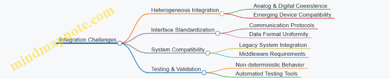
Practical Example 1: Scaling a Spiking Neural Network on a Neuromorphic Chip
Consider a neuromorphic chip designed with 1 million neurons and 256 million synapses. Scaling from a prototype with 10,000 neurons involves:
- Interconnect Design: Using Address-Event Representation (AER) buses to reduce wiring complexity.
- Power Management: Implementing event-driven computation to minimize power usage during inactivity.
- Fault Tolerance: Designing synapse arrays that can bypass defective elements to maintain network integrity.
This example highlights the importance of architectural choices and hardware design to address scalability.
Practical Example 2: Integrating Memristor-Based Synapses with CMOS Neurons
Memristors offer dense, non-volatile synaptic storage but require integration with CMOS neuron circuits:
- Challenge: Different fabrication processes and operating voltages.
- Solution: Use 3D stacking and interface circuits to bridge analog memristor arrays with digital CMOS neurons.
- Outcome: Achieves high synaptic density and energy efficiency but requires careful thermal and signal integrity management.
Best Practices for Addressing Scalability and Integration
- Modular Design: Build neuromorphic systems as interconnected modules to simplify scaling.
- Hierarchical Communication: Implement multi-level communication protocols to reduce bottlenecks.
- Redundancy and Fault Tolerance: Design hardware to detect and compensate for defects.
- Cross-Disciplinary Collaboration: Work closely with materials scientists, circuit designers, and software engineers.
- Incremental Prototyping: Validate designs at smaller scales before full integration.
Summary
Scaling neuromorphic hardware to practical sizes involves overcoming significant challenges in neuron/synapse count, interconnect complexity, power management, and heterogeneous integration. By leveraging modular architectures, advanced fabrication techniques, and robust design methodologies, engineers can build scalable, integrated neuromorphic systems that approach the brain’s remarkable efficiency and adaptability.
9.2 Standardization and Interoperability Issues
Neuromorphic computing is an emerging field characterized by diverse hardware platforms, software frameworks, and communication protocols. While this diversity fosters innovation, it also introduces significant challenges related to standardization and interoperability. Addressing these issues is crucial for enabling seamless integration, scalability, and broader adoption of neuromorphic systems.
Why Standardization Matters
- Facilitates Collaboration: Enables researchers and engineers from different organizations to share designs, tools, and data.
- Reduces Development Time: Common standards prevent reinventing the wheel and allow reuse of components.
- Enhances Compatibility: Ensures that hardware and software components from different vendors can work together.
- Supports Scalability: Standard interfaces and protocols make it easier to build large-scale neuromorphic systems.
Key Areas Requiring Standardization
Interoperability Challenges
-
Diverse Hardware Architectures: Neuromorphic chips vary widely — from fully analog to fully digital, mixed-signal designs, and different neuron/synapse implementations.
-
Proprietary Communication Protocols: Many platforms use custom event-driven protocols (e.g., Address-Event Representation - AER) with incompatible formats.
-
Software Fragmentation: Multiple programming frameworks exist (e.g., Nengo, SpiNNaker API, Loihi SDK), often incompatible with each other.
-
Data Format Inconsistencies: Lack of unified data representations for spike trains, network configurations, and learning rules.
-
Benchmarking Difficulties: No universally accepted benchmarks to compare performance across platforms.
Mind Map: Interoperability Challenges
Practical Examples of Interoperability Issues
-
Example 1: SpiNNaker vs Loihi
- SpiNNaker uses a digital manycore architecture with its own API and communication protocols.
- Loihi employs a specialized on-chip learning and event-driven communication with Intel’s NxSDK.
- Porting a spiking neural network model between these platforms requires significant reimplementation.
-
Example 2: Event-Based Vision Sensors
- Different neuromorphic vision sensors output event streams in proprietary formats.
- Lack of a standard event data format complicates integration with neuromorphic processors from other vendors.
Best Practices to Address Standardization and Interoperability
-
Adopt Open Standards: Engage with initiatives like the Neuromorphic Engineering Community and IEEE Neuromorphic Computing Working Group to contribute to and adopt emerging standards.
-
Use Middleware Layers: Develop or use abstraction layers that translate between different hardware and software interfaces.
-
Define Common Data Formats: Promote formats like Neurodata Without Borders (NWB) adapted for neuromorphic spike data.
-
Benchmark Consistently: Use agreed-upon benchmarks such as Nengo’s benchmarking suite or the BrainScaleS benchmarking framework.
-
Document Thoroughly: Maintain clear and detailed documentation for hardware interfaces, protocols, and software APIs.
Mind Map: Best Practices for Standardization and Interoperability
Example: Middleware for Protocol Translation
Consider a middleware solution that enables a neuromorphic vision sensor outputting AER events in a proprietary format to communicate with a Loihi chip expecting a different event encoding.
- The middleware listens to the sensor’s event stream.
- It translates event addresses and timing to Loihi’s expected format.
- It manages buffering and timing synchronization.
This approach allows heterogeneous components to interoperate without modifying their native implementations.
Summary
Standardization and interoperability remain significant hurdles in neuromorphic computing. By understanding the challenges and adopting best practices—such as engaging with open standards, leveraging middleware, and standardizing data formats—hardware engineers and developers can build more robust, scalable, and collaborative neuromorphic systems. Practical efforts in these directions will accelerate the maturation and adoption of brain-inspired computing technologies.
9.3 Advances in Materials and Device Technologies
Neuromorphic computing relies heavily on innovative materials and device technologies to emulate the complex functionalities of biological neural systems. Recent advances have opened new avenues for creating more efficient, scalable, and adaptive neuromorphic hardware.
Key Material Innovations
- Memristive Devices
- Resistive switching materials enabling synaptic behavior
- Examples: Oxides (TiO2, HfO2), chalcogenides
- Phase-Change Materials (PCM)
- Materials that switch between amorphous and crystalline states
- Used for multi-level synaptic weight storage
- Ferroelectric Materials
- Enable non-volatile memory with fast switching
- Applications in synaptic transistors
- Spintronic Devices
- Utilize electron spin for information processing
- Potential for ultra-low power synapses and neurons
- Organic Electronics
- Flexible, biocompatible materials
- Suitable for biohybrid neuromorphic interfaces
Device Technologies Driving Neuromorphic Progress
-
Memristors as Artificial Synapses
- Mimic synaptic plasticity via conductance modulation
- Example: HP Labs’ TiO2 memristor demonstrating spike-timing-dependent plasticity (STDP)
-
Phase-Change Memory for Multi-Level Synapses
- PCM devices store analog synaptic weights
- Example: IBM’s PCM arrays used in neuromorphic prototypes
-
Ferroelectric Tunnel Junctions (FTJs)
- Enable fast, low-energy synaptic switching
- Example: FTJ-based synapses with high endurance
-
Spintronic Neurons and Synapses
- Magnetic tunnel junctions (MTJs) emulate neuron firing
- Example: Spin-transfer torque devices for stochastic spiking neurons
-
Organic Electrochemical Transistors (OECTs)
- Emulate synaptic functions with ion-electron coupling
- Example: Flexible neuromorphic sensors for wearable applications
Mind Map: Materials and Devices in Neuromorphic Computing
Best Practices for Leveraging Advanced Materials
- Material Selection Based on Application Requirements
- Prioritize endurance for long-term learning applications
- Choose materials with low switching energy for edge devices
- Integration Compatibility
- Ensure materials are compatible with CMOS fabrication
- Consider hybrid integration for combining multiple device types
- Characterization and Reliability Testing
- Perform extensive electrical and thermal cycling tests
- Validate synaptic plasticity behaviors under realistic conditions
Practical Example: Implementing a Memristor-Based Synapse
- Material Choice: Use TiO2 memristors due to their well-studied resistive switching.
- Device Fabrication: Fabricate crossbar arrays to enable high-density synaptic connections.
- Programming Synaptic Weights: Apply voltage pulses to modulate conductance representing synaptic strength.
- Emulating STDP: Design pulse timing schemes to replicate spike-timing-dependent plasticity.
- Testing: Measure conductance changes and retention to ensure reliable learning.
Emerging Trends
- 2D Materials (e.g., MoS2, Graphene)
- Ultra-thin layers enabling novel device physics
- Potential for flexible and transparent neuromorphic devices
- Neuromorphic Photonic Devices
- Use of optical materials for ultrafast spiking neurons
- Example: Silicon photonic circuits for spike communication
- Biohybrid Interfaces
- Integration of living neurons with synthetic devices
- Applications in prosthetics and brain-machine interfaces
In summary, advances in materials and device technologies are pivotal for the evolution of neuromorphic computing hardware. By carefully selecting and integrating these novel materials, engineers can design systems that closely mimic the brain’s efficiency, adaptability, and scalability.
9.4 Emerging Trends: Quantum Neuromorphic and Biohybrid Systems
Neuromorphic computing is rapidly evolving, and two of the most exciting frontiers are Quantum Neuromorphic Systems and Biohybrid Systems. These emerging trends promise to push the boundaries of computational power, efficiency, and integration with biological processes.
Quantum Neuromorphic Systems
Quantum neuromorphic computing combines principles of quantum mechanics with brain-inspired architectures to leverage quantum phenomena such as superposition and entanglement for enhanced neural computation.
Key Concepts:
- Quantum bits (qubits) as neurons or synapses
- Quantum superposition enabling parallel processing of multiple states
- Quantum entanglement facilitating complex connectivity
- Quantum tunneling for synaptic plasticity
Mind Map: Quantum Neuromorphic Systems
Example:
D-Wave Systems have developed quantum annealers that can be adapted for neuromorphic tasks such as optimization and pattern recognition. Researchers have demonstrated small-scale quantum neural networks that exploit quantum superposition to represent multiple neural states simultaneously, potentially accelerating learning and inference.
Best Practice:
When exploring quantum neuromorphic hardware, start with hybrid classical-quantum models. Use classical neuromorphic processors for network architecture and quantum processors for specific sub-tasks like optimization or probabilistic inference. This approach mitigates current hardware limitations and leverages strengths of both domains.
Biohybrid Systems
Biohybrid neuromorphic systems integrate living neural tissue or biological components with electronic hardware to create hybrid platforms that combine the adaptability of biological neurons with the speed and programmability of silicon.
Key Concepts:
- Cultured neuronal networks interfaced with microelectrode arrays (MEAs)
- Organic electronics and biocompatible materials
- Closed-loop systems for real-time interaction
- Plasticity and self-repair capabilities
Mind Map: Biohybrid Neuromorphic Systems
Example:
The Neurogrid project and other biohybrid platforms have demonstrated interfacing cultured rat cortical neurons with silicon chips via MEAs. These systems can learn and adapt in real-time, showing promise for prosthetic control and adaptive robotics.
Another example is the use of organic electrochemical transistors (OECTs) that can communicate with neurons through ionic signaling, enabling low-power, biocompatible interfaces.
Best Practice:
When designing biohybrid systems, prioritize biocompatibility and stable long-term interfaces. Use flexible substrates and organic materials to reduce mechanical mismatch. Employ closed-loop feedback to harness biological plasticity for adaptive system behavior.
Synergies and Future Outlook
The convergence of quantum neuromorphic and biohybrid approaches could lead to revolutionary computing paradigms:
- Quantum-enhanced biohybrid networks for ultra-efficient learning
- Bio-inspired quantum algorithms implemented on hybrid hardware
- Self-healing quantum neuromorphic devices leveraging biological principles
Mind Map: Future Directions
Practical Example:
Imagine a neuroprosthetic device that uses quantum neuromorphic processors to decode neural signals from a biohybrid interface implanted in the brain, enabling real-time adaptive control of robotic limbs with unprecedented speed and accuracy.
Summary
Quantum neuromorphic and biohybrid systems represent the cutting edge of neuromorphic computing, blending physics, biology, and engineering. While challenges remain, their potential to revolutionize computing and human-machine interaction is immense. Hardware engineers and embedded developers should monitor these trends closely, experiment with hybrid designs, and collaborate across disciplines to harness these transformative technologies.
9.5 Best Practice: Staying Current with Research and Industry Developments
Keeping up-to-date with the fast-evolving field of neuromorphic computing is essential for hardware engineers, embedded systems developers, and research engineers. Staying informed enables you to leverage the latest breakthroughs, adopt cutting-edge tools, and anticipate future trends to maintain a competitive edge.
Why Staying Current Matters
- Accelerate Innovation: Integrate novel materials, architectures, and algorithms.
- Avoid Obsolescence: Prevent designs based on outdated technologies.
- Collaborate Effectively: Engage with the community and contribute to standards.
- Identify Opportunities: Spot emerging applications and markets early.
Strategies to Stay Updated
Practical Examples
Setting Up Automated Alerts
Example: Use Google Scholar alerts to track new publications on “neuromorphic hardware”.
- Go to Google Scholar.
- Search for “neuromorphic hardware”.
- Click “Create alert”.
- Receive weekly email summaries of new papers.
This practice ensures you never miss important research developments without manual searching.
Following Key Conferences and Workshops
Example: Attend or follow proceedings from NeurIPS and ISCAS.
- Register for virtual or in-person attendance.
- Review accepted papers and poster sessions.
- Engage in Q&A sessions or forums.
Many conferences now provide recorded talks and slides, enabling asynchronous learning.
Engaging with Industry Leaders
Example: Follow Intel’s Loihi team on Twitter and LinkedIn.
- Gain insights on chip updates, demos, and application showcases.
- Participate in webinars hosted by industry experts.
This helps bridge the gap between academic research and commercial products.
Participating in Online Communities
Example: Join NeuroTechX Slack or Discord channels.
- Ask questions and share experiences.
- Collaborate on open-source neuromorphic projects.
Community engagement accelerates problem-solving and knowledge exchange.
Continuous Learning Through Courses
Example: Enroll in “Neuromorphic Computing” on Coursera.
- Learn foundational concepts and hands-on programming.
- Apply knowledge directly to hardware design challenges.
Regular upskilling ensures your skills remain relevant.
Summary Table: Recommended Resources
| Resource Type | Examples | Purpose |
|---|---|---|
| Conferences | NeurIPS, ISCAS, DATE | Latest research and networking |
| Journals | IEEE TNNLS, Nature Electronics | Peer-reviewed studies |
| Industry Channels | Intel Loihi, BrainChip, IBM TrueNorth | Product updates and demos |
| Online Communities | NeuroTechX, ResearchGate | Collaboration and Q&A |
| Learning Platforms | Coursera, edX | Structured courses |
| Alert Tools | Google Scholar Alerts, arXiv RSS | Automated paper tracking |
Final Tip
Create a personalized “Neuromorphic Computing Dashboard” combining RSS feeds, calendar reminders for conferences, and links to key forums. This centralized approach streamlines your information flow and helps maintain a consistent learning habit.
By integrating these best practices into your workflow, you ensure that your expertise in neuromorphic computing hardware remains sharp, relevant, and impactful.
9.6 Practical Example: Roadmap for Developing Next-Generation Neuromorphic Hardware
Developing next-generation neuromorphic hardware requires a structured roadmap that integrates multidisciplinary knowledge, cutting-edge technology, and iterative design practices. This practical example outlines a comprehensive step-by-step approach, supported by mind maps and real-world examples, to guide hardware engineers and embedded systems developers through the process.
Step 1: Define Application and Performance Goals
- Identify target applications (e.g., robotics, sensory processing, brain-machine interfaces).
- Set performance metrics: power consumption, latency, scalability, learning capability.
- Determine constraints: size, cost, integration with existing systems.
Example: Designing a neuromorphic chip for low-power event-based vision in autonomous drones.
Mind Map: Define Application and Goals
Step 2: Biological Inspiration and Model Selection
- Choose neuron and synapse models (e.g., Leaky Integrate-and-Fire, Hodgkin-Huxley).
- Incorporate plasticity mechanisms (STDP, Hebbian learning).
- Analyze biological energy efficiency and parallelism for hardware mapping.
Example: Selecting Leaky Integrate-and-Fire neurons with STDP for adaptive learning in hardware.
Mind Map: Biological Model Selection
Step 3: Hardware Architecture Design
- Decide on analog, digital, or mixed-signal implementation.
- Design event-driven asynchronous communication (e.g., Address-Event Representation).
- Plan network topology (feedforward, recurrent, modular).
Example: Designing a mixed-signal architecture with asynchronous event-driven communication for real-time processing.
Mind Map: Hardware Architecture

Step 4: Component Selection and Integration
- Choose synaptic devices (memristors, phase-change memory).
- Integrate neuron circuits and synaptic arrays.
- Ensure scalability and fault tolerance.
Example: Using memristor arrays for synaptic weights to enable dense and energy-efficient storage.
Mind Map: Component Integration
Step 5: Simulation and Prototyping
- Use simulation tools (e.g., Nengo, Brian2, Loihi SDK) to validate models.
- Prototype on FPGA or custom silicon.
- Iterate design based on performance and power analysis.
Example: Simulating a spiking neural network on Loihi SDK before FPGA prototyping.
Mind Map: Simulation and Prototyping
Step 6: Fabrication and Testing
- Fabricate chip using selected semiconductor process.
- Perform functional testing and benchmarking.
- Validate learning capability and robustness.
Example: Testing chip response to sensory input patterns and measuring power consumption.
Mind Map: Fabrication and Testing

Step 7: Deployment and Feedback
- Integrate neuromorphic hardware into target systems.
- Monitor real-world performance.
- Collect feedback for next design iteration.
Example: Deploying neuromorphic vision chip in a drone and analyzing adaptive response to dynamic environments.
Mind Map: Deployment and Feedback
Summary Mind Map: Roadmap Overview
Final Notes
This roadmap emphasizes an iterative, multidisciplinary approach blending neuroscience, hardware design, and software simulation. By following these steps and leveraging best practices, engineers can systematically develop neuromorphic hardware that pushes the boundaries of energy-efficient, adaptive computing.
Additional Resources:
- Intel Loihi Neuromorphic Research Chip: https://www.intel.com/content/www/us/en/research/neuromorphic-computing.html
- Nengo Neural Simulator: https://www.nengo.ai/
- Memristor-Based Synapse Research: https://ieeexplore.ieee.org/document/XXXXXXX
10. Resources and Tools for Neuromorphic Engineers
10.1 Open-Source Hardware and Software Platforms
Neuromorphic computing is a rapidly evolving field that benefits greatly from open-source initiatives. These platforms provide hardware designs, software frameworks, and community-driven tools that accelerate development, experimentation, and deployment. Leveraging open-source resources allows hardware engineers, embedded systems developers, and research engineers to prototype faster, share innovations, and build upon existing work.
Why Open-Source Matters in Neuromorphic Computing
- Accessibility: Lowers barriers to entry by providing free access to designs and code.
- Collaboration: Encourages community contributions, bug fixes, and feature enhancements.
- Transparency: Enables detailed inspection and understanding of system internals.
- Rapid Innovation: Facilitates faster iteration cycles and cross-pollination of ideas.
Key Open-Source Neuromorphic Hardware Platforms
Open-Source Neuromorphic Hardware Platforms Mind Map
Prominent Open-Source Neuromorphic Software Frameworks
Open-Source Neuromorphic Software Frameworks Mind Map
Best Practices for Using Open-Source Platforms
- Start Small: Begin with simple example projects provided by the platform to understand workflows.
- Leverage Community Forums: Engage with user groups and forums for troubleshooting and tips.
- Contribute Back: Share improvements, bug fixes, or documentation to strengthen the ecosystem.
- Combine Tools: Use hardware platforms with compatible software frameworks for seamless integration.
- Document Your Work: Maintain clear documentation to facilitate reproducibility and collaboration.
Practical Example: Building a Basic Spiking Neural Network Using Nengo and Deploying on SpiNNaker
- Setup: Install Nengo and configure the SpiNNaker backend.
- Model Design: Create a simple spiking neuron network to classify input patterns.
- Simulation: Run the model on a local simulator to verify functionality.
- Deployment: Transfer the model to SpiNNaker hardware for real-time execution.
- Evaluation: Measure latency, power consumption, and accuracy.
This example demonstrates the synergy between open-source software and hardware platforms, enabling practical neuromorphic system development.
Summary
Open-source hardware and software platforms form the backbone of practical neuromorphic computing development. By tapping into these resources, engineers and researchers can accelerate innovation, reduce costs, and foster a collaborative environment that pushes the boundaries of brain-inspired computing.
10.2 Simulation and Emulation Environments
Simulation and emulation environments are critical tools for hardware engineers and embedded systems developers working in neuromorphic computing. They allow you to model, test, and optimize neuromorphic architectures before committing to costly fabrication or deployment. These environments help bridge the gap between theoretical neuroscience models and practical hardware implementations.
Why Use Simulation and Emulation?
- Cost Efficiency: Avoid expensive hardware iterations by validating designs virtually.
- Design Exploration: Quickly prototype various neuron models, synaptic plasticity rules, and network topologies.
- Debugging and Validation: Identify bottlenecks, timing issues, or unexpected behaviors early.
- Performance Prediction: Estimate power consumption, latency, and scalability.
Key Types of Environments
- Simulation: Software-based modeling of neuromorphic systems, often at various abstraction levels (from detailed neuron dynamics to high-level network behavior).
- Emulation: Hardware or FPGA-based platforms that mimic neuromorphic hardware behavior in real-time or accelerated time.
Popular Simulation Tools
NEST Simulator
- Focus: Large-scale spiking neural networks.
- Features: Supports various neuron and synapse models, parallel computation.
- Example Use: Simulating cortical microcircuits to study emergent behavior.
Brian2
- Focus: Flexible and easy-to-use spiking neural network simulator.
- Features: Python-based, supports custom neuron models.
- Example Use: Rapid prototyping of novel neuron dynamics.
NEURON
- Focus: Detailed compartmental neuron models.
- Features: Biophysically realistic simulations.
- Example Use: Modeling dendritic processing in pyramidal neurons.
SpiNNaker Software Stack
- Focus: Mapping spiking neural networks onto SpiNNaker hardware.
- Features: Real-time emulation, event-driven simulation.
- Example Use: Testing large-scale brain models on neuromorphic hardware.
Emulation Platforms
FPGA-based Emulators
- Use FPGAs to implement neuron and synapse models for real-time testing.
- Example: Implementing a spiking neural network on Xilinx or Intel FPGAs to evaluate timing and power.
Dedicated Neuromorphic Chips
- Platforms like Intel Loihi or IBM TrueNorth provide hardware emulation environments.
- Example: Running a pattern recognition algorithm directly on Loihi to measure latency.
Best Practices for Using Simulation and Emulation Environments
- Start Simple: Begin with small networks and basic neuron models before scaling.
- Validate Models: Cross-check simulation results with biological data or hardware measurements.
- Iterate Frequently: Use simulation feedback to refine hardware design and parameters.
- Leverage Parallelism: Use multi-core or GPU acceleration to speed up simulations.
- Document Configurations: Keep track of parameters and versions for reproducibility.
Practical Example: Simulating a Spiking Neural Network with Brian2
Mind Map: Brian2 Simulation Workflow
Example Code Snippet:
from brian2 import *

# Define neuron parameters
tau = 10*ms
v_rest = -70*mV
v_reset = -65*mV
v_threshold = -50*mV

# Define neuron model equations
eqs = '''
 dv/dt = (v_rest - v) / tau : volt
'''

# Create neuron group
G = NeuronGroup(100, eqs, threshold='v>v_threshold', reset='v = v_reset', method='exact')
G.v = v_rest

# Create synapses
S = Synapses(G, G, on_pre='v_post += 1*mV')
S.connect(p=0.1)

# Record spikes
spikemon = SpikeMonitor(G)

# Run simulation
run(1*second)

# Plot results
import matplotlib.pyplot as plt
plt.figure(figsize=(10,4))
plt.plot(spikemon.t/ms, spikemon.i, '.k')
plt.xlabel('Time (ms)')
plt.ylabel('Neuron index')
plt.title('Spike Raster Plot')
plt.show()
Mind Map: Simulation vs Emulation Decision Factors
Summary
Simulation and emulation environments form the backbone of neuromorphic hardware development workflows. By leveraging tools like Brian2, NEST, and FPGA platforms, engineers can prototype, validate, and optimize neuromorphic designs effectively. Combining both approaches ensures a smoother transition from concept to deployment, reducing risks and accelerating innovation.
10.3 Community and Collaboration Networks
In the rapidly evolving field of neuromorphic computing, community and collaboration networks play a pivotal role in accelerating innovation, sharing knowledge, and fostering partnerships between hardware engineers, embedded systems developers, and research engineers. Engaging with these networks can provide access to cutting-edge research, open-source projects, hardware platforms, and expert advice.
Why Community and Collaboration Matter
- Knowledge Sharing: Access to tutorials, research papers, and best practices.
- Resource Pooling: Shared hardware designs, datasets, and software tools.
- Collaborative Development: Joint projects and co-design efforts.
- Networking: Opportunities to connect with experts and peers.
Key Types of Communities
Open-Source Communities
-
Nengo: A Python-based neural simulation platform with active forums and collaborative projects. Great for prototyping neuromorphic algorithms.
- Example: A hardware engineer contributed a custom neuron model to Nengo, improving simulation accuracy.
-
SpiNNaker: A massively parallel neuromorphic computing platform with an active developer community.
- Example: Embedded systems developers share hardware integration tips on the SpiNNaker mailing list.
-
Loihi SDK (Intel): Intel’s neuromorphic chip SDK with an active GitHub repository and user forums.
- Example: Researchers collaborate on spike-based learning algorithms and share code snippets.
Research Consortia and Industry Groups
-
Human Brain Project (HBP): European initiative with collaborative platforms for neuromorphic hardware and software.
- Example: Joint workshops where engineers and neuroscientists co-develop hardware models.
-
DARPA SyNAPSE: U.S. government program fostering collaboration between academia, industry, and government labs.
- Example: Multi-institutional teams share progress on memristor-based synaptic devices.
-
IEEE Neuromorphic Computing Community: Provides standards, organizes webinars, and publishes newsletters.
- Example: Hardware architects participate in working groups to define neuromorphic benchmarks.
Online Platforms for Collaboration
-
GitHub: Central hub for sharing code, hardware designs, and documentation.
- Example: A research engineer forks a neuromorphic simulator repo to add custom synapse models.
-
Stack Exchange: Platform for asking technical questions and sharing solutions.
- Example: Embedded developers troubleshoot FPGA integration issues with neuromorphic chips.
-
Reddit r/neuromorphic: Informal discussions, news sharing, and community support.
- Example: Announcements of new hardware releases and conference calls for papers.
-
Slack/Discord Channels: Real-time collaboration spaces for project teams and interest groups.
- Example: A neuromorphic hardware startup uses Discord to coordinate development and gather user feedback.
Conferences and Workshops
-
Telluride Neuromorphic Cognition Workshop: Annual event fostering interdisciplinary collaboration.
- Example: Hardware engineers present prototype designs and receive feedback from neuroscientists.
-
International Neuromorphic Engineering Conference (INEC): Premier conference for neuromorphic hardware and algorithms.
- Example: Collaborative sessions where participants form new research partnerships.
-
NeurIPS Neuromorphic Workshops: Focused workshops on neuromorphic computing topics.
- Example: Developers share software tools and hardware benchmarks.
Best Practices for Engaging with Communities
- Contribute Actively: Share your code, designs, and findings to build reputation and trust.
- Participate in Discussions: Ask questions and provide answers to deepen understanding.
- Attend Events: Join conferences and workshops to network and learn about emerging trends.
- Leverage Collaboration Tools: Use GitHub, Slack, and other platforms to streamline teamwork.
- Document Your Work: Maintain clear documentation to facilitate knowledge transfer.
Practical Example: Joining and Contributing to the SpiNNaker Community
- Join the Mailing List: Subscribe to receive updates and participate in discussions.
- Access the GitHub Repository: Clone the SpiNNaker software and hardware repos.
- Identify an Issue or Feature: Review open issues or propose new features.
- Develop and Test: Implement changes and test on SpiNNaker hardware or simulators.
- Submit a Pull Request: Share your contribution with the community.
- Engage in Feedback: Respond to reviews and iterate.
This process exemplifies collaborative development, accelerating both individual learning and community progress.
By actively engaging with community and collaboration networks, hardware engineers, embedded systems developers, and research engineers can stay at the forefront of neuromorphic computing innovation, leveraging collective expertise to overcome challenges and create impactful solutions.
10.4 Educational Materials and Training Programs
Neuromorphic computing is a rapidly evolving interdisciplinary field that combines neuroscience, hardware architecture, and computational modeling. For hardware engineers, embedded systems developers, and research engineers, gaining a solid foundation through educational materials and structured training programs is essential to effectively contribute to this domain.
Key Educational Resources
-
Textbooks and Reference Books
- Neuromorphic Engineering by André van Schaik: Covers fundamentals of neuromorphic circuits and systems.
- Spiking Neuron Models by Wulfram Gerstner and Werner M. Kistler: Deep dive into neuron modeling.
- Principles of Neural Science by Eric Kandel et al.: Foundational neuroscience concepts.
-
Online Courses and MOOCs
- Neuromorphic Computing on Coursera (offered by University of Zurich): Covers hardware and software aspects.
- Computational Neuroscience by University of Washington on Coursera: Focuses on neuron models and network dynamics.
- Introduction to Embedded Systems by University of Texas at Austin on edX: Useful for embedded integration.
-
Workshops and Summer Schools
- Telluride Neuromorphic Cognition Engineering Workshop: Hands-on training with neuromorphic hardware.
- International Summer School on Neuromorphic Computing: Covers latest research and applications.
-
Research Papers and Journals
- Frontiers in Neuroscience - Neuromorphic Engineering section.
- IEEE Transactions on Neural Networks and Learning Systems.
- Nature Electronics - Neuromorphic hardware articles.
-
Community Platforms and Forums
- Neuromorphic Computing Community (NCC): Discussion forums and resource sharing.
- GitHub repositories with open-source neuromorphic projects.
Mind Map: Educational Pathways in Neuromorphic Computing
Best Practices for Learning Neuromorphic Computing
- Start with Fundamentals: Build a strong understanding of neuroscience basics and traditional hardware design.
- Hands-On Practice: Engage with simulation tools like Brian2, Nengo, or hardware platforms such as Intel Loihi or SpiNNaker.
- Join Communities: Participate in forums and workshops to stay updated and collaborate.
- Iterative Learning: Combine theoretical study with practical projects to reinforce concepts.
Practical Example: Structured Learning Plan for a Hardware Engineer
| Week | Focus Area | Resources & Activities |
|---|---|---|
| 1-2 | Neuroscience Basics | Read chapters from Principles of Neural Science; watch introductory videos on neuron function. |
| 3-4 | Neuromorphic Hardware Overview | Study Neuromorphic Engineering book; explore Intel Loihi architecture documentation. |
| 5-6 | Simulation Tools | Complete tutorials on Brian2 and Nengo; simulate simple spiking neuron models. |
| 7-8 | Programming & Algorithms | Learn event-driven programming; implement STDP learning rule in simulation. |
| 9-10 | Embedded Integration | Study embedded systems course; experiment with interfacing neuromorphic chips with microcontrollers. |
| 11-12 | Project & Community Engagement | Build a small neuromorphic application; present findings in online forums or workshops. |
Mind Map: Training Program Components for Neuromorphic Engineers
By leveraging these educational materials and training programs, engineers can effectively bridge the gap between theory and practice, enabling them to design, implement, and optimize neuromorphic hardware systems inspired by the brain.
10.5 Best Practice: Leveraging Resources for Continuous Learning
Continuous learning is essential for hardware engineers, embedded systems developers, and research engineers working in neuromorphic computing due to the fast-evolving nature of the field. Leveraging the right resources effectively can accelerate your expertise, keep you updated with the latest advancements, and foster innovation.
Why Continuous Learning Matters in Neuromorphic Computing
- Rapid technological advancements in materials, architectures, and algorithms.
- Interdisciplinary nature requiring knowledge in neuroscience, hardware design, and software.
- Emerging standards and tools that impact design and deployment.
Key Strategies to Leverage Resources
Structured Learning through Online Courses and Tutorials
- Platforms like Coursera, edX, and Udacity offer courses on computational neuroscience, neuromorphic engineering, and embedded systems.
- Example: “Neuromorphic Computing and Engineering” course by the University of Zurich on Coursera.
Engaging with Open-Source Projects and Hardware Platforms
- Hands-on experience with platforms like Loihi (Intel), SpiNNaker, and BrainScaleS.
- Contribute to or study repositories on GitHub related to neuromorphic software frameworks (e.g., Nengo, Brian2).
Participating in Conferences, Workshops, and Webinars
- Attend events such as the International Neuromorphic Engineering Workshop (INEW) or IEEE conferences.
- Example: Join virtual workshops to learn about the latest memristor-based synaptic devices.
Reading and Curating Research Papers and Technical Reports
- Use tools like Google Scholar alerts and arXiv to stay updated.
- Summarize and discuss papers within your team or community to deepen understanding.
Joining Professional Communities and Discussion Forums
- Engage in forums like NeuroTechX, ResearchGate, and specialized LinkedIn groups.
- Share knowledge, ask questions, and collaborate on projects.
Setting Up a Personal Knowledge Management System
- Use tools like Notion, Obsidian, or Roam Research to organize notes, mind maps, and resources.
- Regularly review and update your knowledge base.
Mind Map: Leveraging Resources for Continuous Learning
Mind Map: Example - Open-Source Platforms and Tools
Practical Example: Setting Up a Continuous Learning Routine
-
Weekly Schedule:
- Monday: Review recent research papers (use Google Scholar alerts).
- Wednesday: Hands-on coding with neuromorphic frameworks (e.g., Nengo).
- Friday: Participate in community discussions or webinars.
-
Monthly Goals:
- Complete one online course module.
- Build or simulate a small neuromorphic circuit or network.
- Write a summary blog post or internal report to consolidate learning.
-
Tools:
- Use Notion to track progress and store notes.
- Create mind maps in format to visualize concepts.
Additional Tips
- Collaborate: Pair with colleagues or join study groups to share insights.
- Teach: Explaining concepts to others reinforces your own understanding.
- Experiment: Apply new knowledge in small projects to gain practical experience.
- Stay Curious: Follow thought leaders and emerging startups in neuromorphic computing.
By integrating these practices and resources into your professional routine, you can maintain a strong grasp of neuromorphic computing developments and contribute effectively to advancing hardware architectures inspired by the brain.
10.6 Practical Example: Setting Up a Neuromorphic Development Environment
Setting up a neuromorphic development environment is a foundational step for hardware engineers, embedded systems developers, and research engineers aiming to design, simulate, and deploy neuromorphic systems effectively. This section guides you through the essential tools, platforms, and workflows, complemented by mind maps and examples to streamline your setup.
Step 1: Define Your Development Goals
Before diving into tools and hardware, clarify your objectives:
- Are you focusing on hardware design, simulation, or application development?
- Do you want to work with analog, digital, or mixed-signal neuromorphic systems?
- Are you targeting embedded deployment or research prototyping?
Mind Map: Defining Development Goals
Step 2: Select Hardware Platforms
Common neuromorphic hardware platforms include:
- Intel Loihi: A digital neuromorphic research chip supporting spiking neural networks.
- BrainScaleS: Mixed-signal accelerated neuromorphic hardware.
- SpiNNaker: A massively parallel digital neuromorphic platform.
- Neurogrid: Analog/digital hybrid system.
Example: For embedded systems developers, Intel Loihi offers SDKs and hardware kits suitable for prototyping.
Mind Map: Hardware Platforms
Step 3: Choose Software Frameworks and Tools
Software frameworks facilitate programming, simulation, and deployment:
- Nengo: High-level neural simulator supporting neuromorphic hardware.
- Brian2: Flexible spiking neural network simulator.
- PyNN: Simulator-independent language for spiking neural networks.
- NxSDK: Intel Loihi’s software development kit.
- SpiNNTools: Tools for SpiNNaker programming.
Example: Using Nengo with Intel Loihi allows seamless transition from simulation to hardware deployment.
Mind Map: Software Frameworks
Step 4: Set Up Your Development Environment
Hardware Setup:
- Obtain hardware development kits (e.g., Intel Loihi Research Chip).
- Connect hardware to your workstation via USB/Ethernet.
Software Setup:
- Install Python (preferably 3.7+).
- Set up virtual environments to manage dependencies.
- Install required packages:
pip install nengo nengo-loihi brian2 pyNN - Download and install vendor-specific SDKs (e.g., NxSDK for Loihi).
Example: Setting up a Python virtual environment for neuromorphic development:
python3 -m venv neuromorphic-env
source neuromorphic-env/bin/activate
pip install nengo nengo-loihi
Step 5: Verify Installation with a Sample Project
Run a simple spiking neuron simulation using Nengo and deploy it to Loihi (if hardware is available).
import nengo
import nengo_loihi

model = nengo.Network()
with model:
    stim = nengo.Node([0.5])
    neuron = nengo.Ensemble(1, dimensions=1)
    nengo.Connection(stim, neuron)

with nengo_loihi.Simulator(model) as sim:
    sim.run(1.0)
    print('Simulation complete')
Step 6: Integrate Debugging and Profiling Tools
- Use logging and visualization tools like Nengo GUI or Matplotlib.
- Profile performance and power consumption if hardware supports it.
Example: Visualizing spike trains:
import matplotlib.pyplot as plt

plt.plot(sim.trange(), sim.data[neuron.neurons.spikes])
plt.xlabel('Time (s)')
plt.ylabel('Spikes')
plt.show()
Summary Mind Map: Neuromorphic Development Environment Setup
By following these steps and leveraging the provided examples and mind maps, you can establish a robust neuromorphic development environment tailored to your project needs. This foundation enables efficient experimentation, prototyping, and deployment of brain-inspired hardware systems.
11. Conclusion and Call to Action
11.1 Recap of Key Concepts and Practices
Neuromorphic computing represents a paradigm shift in hardware architecture, inspired directly by the structure and function of the biological brain. Throughout this blog, we’ve explored foundational concepts, hardware design principles, programming methodologies, and real-world applications. This section synthesizes these insights into a cohesive overview, reinforced with mind maps and practical examples to solidify understanding.
Mind Map: Core Concepts of Neuromorphic Computing
Mind Map: Best Practices in Neuromorphic Hardware Development
Key Concepts Recap with Examples
-
Biological Inspiration
- Example: Implementing Spike-Timing Dependent Plasticity (STDP) in memristor synapses to mimic learning mechanisms found in biological neurons.
-
Hardware Architectures
- Example: Designing a mixed-signal neuromorphic chip that uses analog circuits for neuron dynamics and digital logic for network control, balancing precision and power efficiency.
-
Core Components
- Example: Using Address-Event Representation (AER) to asynchronously communicate spikes between neuron cores, reducing latency and power consumption.
-
Design Methodologies
- Example: Employing hardware-software co-design by simulating spiking neural networks in software before mapping onto FPGA-based neuromorphic prototypes.
-
Programming Neuromorphic Hardware
- Example: Implementing a supervised learning algorithm on a neuromorphic platform to perform pattern recognition on event-based camera data.
-
Embedded Systems Integration
- Example: Deploying a neuromorphic sensor fusion module in an IoT edge device, optimizing for low power and real-time response.
-
Applications
- Example: Using neuromorphic vision systems for low-latency object detection in autonomous drones.
Summary
Neuromorphic computing is a multidisciplinary field that requires a deep understanding of neuroscience principles, hardware design, and software programming. By following best practices such as selecting appropriate architectures, leveraging event-driven communication, and iterative prototyping, engineers can create efficient, scalable, and robust neuromorphic systems. Practical examples throughout this blog have demonstrated how these concepts translate into real-world applications, from robotics to embedded IoT devices.
This recap serves as a foundation for your continued exploration and innovation in neuromorphic computing, empowering hardware engineers, embedded systems developers, and research engineers to harness brain-inspired hardware for next-generation computing challenges.
11.2 The Role of Hardware Engineers and Developers in Neuromorphic Computing
Neuromorphic computing represents a paradigm shift in how we design and implement computing systems, drawing inspiration from the brain’s architecture and functionality. Hardware engineers and developers play a pivotal role in transforming these biological principles into practical, efficient, and scalable hardware solutions. This section explores their critical responsibilities, challenges, and opportunities, supported by mind maps and real-world examples.
Key Responsibilities of Hardware Engineers and Developers
- Designing Neuromorphic Circuits: Translating neural models into analog, digital, or mixed-signal circuits that emulate neuron and synapse behavior.
- Selecting and Integrating Components: Choosing appropriate devices such as memristors, phase-change memory, or CMOS transistors and integrating them cohesively.
- Optimizing for Power and Efficiency: Leveraging event-driven and asynchronous design principles to minimize energy consumption.
- Ensuring Scalability and Robustness: Creating architectures that can scale to large networks while maintaining fault tolerance.
- Collaborating with Software Teams: Facilitating hardware-software co-design to enable efficient programming and deployment.
Mind Map: Roles and Responsibilities of Hardware Engineers in Neuromorphic Computing
Example 1: Designing a Low-Power Spiking Neuron Circuit
A hardware engineer tasked with implementing a spiking neuron model opts for a mixed-signal approach. By combining analog circuits for neuron membrane potential integration and digital logic for spike generation and communication, the design achieves low latency and power efficiency. The engineer uses asynchronous event-driven signaling to reduce unnecessary switching activity, resulting in a neuromorphic core that consumes milliwatts instead of watts.
Challenges Faced by Hardware Engineers
- Device Variability: Emerging devices like memristors exhibit variability that must be accounted for in design.
- Complexity of Neural Models: Mapping biologically realistic models to hardware-friendly abstractions requires trade-offs.
- Integration with Conventional Systems: Ensuring seamless communication between neuromorphic chips and traditional processors.
- Limited Toolchains: Compared to conventional hardware, neuromorphic design tools are still maturing.
Mind Map: Challenges in Neuromorphic Hardware Development

Example 2: Integrating Neuromorphic Chips into Embedded Systems
An embedded systems developer integrates a neuromorphic vision sensor into an autonomous drone. The developer must manage power constraints, real-time data processing, and communication with the drone’s flight controller. By leveraging asynchronous event-driven data from the neuromorphic sensor, the system reduces latency and power consumption, enabling longer flight times and faster obstacle detection.
Opportunities for Hardware Engineers and Developers
- Pioneering New Architectures: Innovating beyond von Neumann bottlenecks to create brain-inspired computing platforms.
- Cross-Disciplinary Collaboration: Working closely with neuroscientists, software engineers, and material scientists.
- Contributing to Open-Source Initiatives: Participating in community-driven hardware and software projects.
- Driving AI at the Edge: Enabling efficient, low-latency AI applications in embedded and IoT devices.
Mind Map: Opportunities for Hardware Engineers in Neuromorphic Computing
Final Thoughts
Hardware engineers and developers are the architects and builders of neuromorphic computing’s future. Their expertise in circuit design, component integration, and system optimization is essential to realize the promise of brain-inspired computing. By embracing interdisciplinary collaboration and continuous learning, they can overcome challenges and drive innovation that bridges biology and technology.
Summary Table: Role Overview
| Role Aspect | Description | Example |
|---|---|---|
| Circuit Design | Creating neuron and synapse circuits | Mixed-signal spiking neuron design |
| Component Selection | Choosing devices like memristors or CMOS | Using memristors for synaptic weights |
| Power Optimization | Implementing event-driven and asynchronous designs | Asynchronous spike communication |
| Scalability & Robustness | Designing fault-tolerant, modular architectures | Modular neuromorphic cores |
| Collaboration | Working with software and neuroscience teams | Hardware-software co-design for learning algorithms |
This comprehensive understanding empowers hardware engineers and developers to contribute meaningfully to the evolving field of neuromorphic computing.
11.3 Opportunities for Innovation and Impact
Neuromorphic computing stands at the crossroads of neuroscience, hardware engineering, and computer science, offering a fertile ground for innovation that can profoundly impact multiple industries. As hardware engineers, embedded systems developers, and research engineers, understanding these opportunities can help you pioneer solutions that leverage brain-inspired architectures for real-world challenges.
Mind Map: Opportunities for Innovation in Neuromorphic Computing
Energy-Efficient Computing
Neuromorphic hardware mimics the brain’s remarkable energy efficiency, making it ideal for battery-powered and edge devices where power is limited.
Example:
- Designing a wearable health monitor that uses a neuromorphic chip to continuously analyze biosignals with minimal power consumption, extending battery life significantly compared to traditional processors.
Best Practice:
- Focus on event-driven architectures that process data only when necessary, reducing idle power draw.
Advanced AI and Machine Learning
Neuromorphic systems enable on-chip learning and adaptation, supporting AI models that evolve in real-time without cloud dependency.
Example:
- Implementing a neuromorphic spiking neural network that learns to recognize new spoken commands on-device, adapting to user-specific accents and speech patterns.
Best Practice:
- Leverage spike-timing-dependent plasticity (STDP) algorithms to implement unsupervised learning directly in hardware.
Robotics and Autonomous Systems
Neuromorphic hardware can provide low-latency sensor processing and adaptive control, critical for responsive and energy-efficient robots.
Example:
- A drone using neuromorphic vision sensors and processors to navigate complex environments in real-time, reacting faster than conventional systems.
Best Practice:
- Integrate event-based cameras with neuromorphic processors to reduce data bandwidth and improve reaction time.
Brain-Machine Interfaces (BMI)
Neuromorphic devices can decode neural signals with high temporal precision, enabling more natural and responsive prosthetics or cognitive augmentation.
Example:
- Developing a prosthetic hand controlled by a neuromorphic interface that interprets motor cortex spikes, allowing fluid and intuitive movement.
Best Practice:
- Utilize low-latency, spike-based processing to minimize delay between neural signal acquisition and actuator response.
Healthcare and Biomedical Applications
Real-time processing of complex biomedical signals can enable personalized diagnostics and therapies.
Example:
- An implantable neuromorphic chip that monitors epileptic brain activity and triggers stimulation to prevent seizures.
Best Practice:
- Design for ultra-low power and biocompatibility to ensure safe, long-term operation inside the human body.
Internet of Things (IoT)
Embedding neuromorphic chips in IoT devices can enable distributed intelligence, reducing reliance on cloud computing and enhancing privacy.
Example:
- Smart environmental sensors that locally analyze data streams (e.g., air quality, sound) and only transmit relevant alerts.
Best Practice:
- Employ hierarchical neuromorphic networks to balance local processing and network communication efficiently.
Materials and Device Innovation
Innovations in memristive and nanoscale devices can unlock new synaptic functionalities and scalability.
Example:
- Using phase-change memory devices as synapses to achieve high-density, low-power neuromorphic arrays.
Best Practice:
- Collaborate with materials scientists to co-design hardware that exploits device physics for synaptic plasticity.
Quantum Neuromorphic Computing
Combining quantum computing principles with neuromorphic architectures could open new computational paradigms.
Example:
- Exploring quantum memristors to implement probabilistic synapses for enhanced learning capabilities.
Best Practice:
- Stay informed on emerging quantum device research and explore hybrid system designs.
Education and Research Tools
Accessible neuromorphic platforms and open-source tools accelerate innovation and skill development.
Example:
- Developing educational kits that allow students and engineers to prototype neuromorphic circuits with intuitive interfaces.
Best Practice:
- Engage with open communities and contribute to shared repositories to foster collaborative progress.
Summary
The opportunities for innovation in neuromorphic computing span multiple domains, from ultra-efficient edge devices to advanced AI, robotics, healthcare, and beyond. By embracing brain-inspired hardware principles and integrating best practices such as event-driven processing, on-chip learning, and interdisciplinary collaboration, engineers can create impactful solutions that push the boundaries of current technology.
Exploring these avenues not only advances the field but also addresses pressing societal challenges related to energy consumption, real-time intelligence, and human-machine interaction.
11.4 Encouraging Experimentation and Open Collaboration
Neuromorphic computing is a rapidly evolving field where innovation thrives on experimentation and open collaboration. Hardware engineers, embedded systems developers, and research engineers can accelerate progress by embracing a culture of sharing, iterative testing, and community engagement. This section explores practical ways to foster experimentation and collaboration, supported by illustrative mind maps and real-world examples.
Why Experimentation Matters
- Neuromorphic systems often involve novel architectures and components that defy traditional design rules.
- Experimentation allows for rapid prototyping, testing hypotheses, and discovering unexpected behaviors.
- Iterative design cycles help optimize power, performance, and scalability.
Benefits of Open Collaboration
- Sharing designs, data, and code accelerates collective learning.
- Collaborative projects pool diverse expertise, from materials science to algorithm development.
- Open standards and interoperability foster ecosystem growth.
Mind Map: Encouraging Experimentation
Mind Map: Open Collaboration Strategies
Practical Examples
Example 1: Rapid Prototyping with FPGA-Based Neuromorphic Platforms
A hardware engineer uses an FPGA development board to emulate spiking neural networks before committing to ASIC design. By iterating on neuron models and synaptic parameters in simulation and hardware, the engineer quickly identifies optimal configurations for energy efficiency and latency.
Example 2: Collaborative Development on GitHub
A research team shares their neuromorphic sensor fusion algorithms on GitHub under an open-source license. Contributors worldwide submit improvements, bug fixes, and new features. The team maintains detailed documentation and encourages issue reporting, fostering a vibrant community around their project.
Example 3: Cross-Disciplinary Hackathon
An embedded systems developer joins a neuromorphic computing hackathon where neuroscientists, hardware architects, and software developers collaborate to build a brain-inspired robotic controller. The event emphasizes rapid experimentation, knowledge exchange, and open sharing of code and hardware designs.
Best Practices to Foster Experimentation and Collaboration
- Adopt Open Standards: Use and contribute to open hardware and software standards to ensure interoperability.
- Use Version Control: Maintain all code and hardware description files in repositories like GitHub or GitLab.
- Document Thoroughly: Keep detailed records of experiments, configurations, and outcomes.
- Share Results Publicly: Publish datasets, benchmarks, and even negative results to help the community learn.
- Engage with Communities: Participate in forums, workshops, and conferences to exchange ideas.
- Encourage Cross-Disciplinary Teams: Combine expertise from neuroscience, hardware design, and software engineering.
By embedding these practices into your workflow, you contribute not only to your projects’ success but also to the broader neuromorphic computing community’s advancement. Experiment boldly, share openly, and collaborate widely to unlock the full potential of brain-inspired hardware.
11.5 Final Practical Example: Designing Your First Neuromorphic Project
Embarking on your first neuromorphic computing project can be both exciting and challenging. This section guides you through a practical example of designing a simple neuromorphic system — a spiking neural network (SNN) for basic pattern recognition — integrating best practices and clear mind maps to visualize the process.
Step 1: Define the Project Scope and Objectives
- Objective: Build a neuromorphic system that recognizes simple binary patterns (e.g., distinguishing between two shapes).
- Target Hardware: Use a digital neuromorphic platform such as Intel’s Loihi or a simulated environment like Nengo.
- Constraints: Low power consumption, real-time processing, and scalability.
Mind Map: Project Planning
Step 2: Choose the Neuromorphic Architecture
- Select a simple feedforward spiking neural network.
- Use Leaky Integrate-and-Fire (LIF) neurons for simplicity and biological plausibility.
- Employ Spike-Timing Dependent Plasticity (STDP) for unsupervised learning.
Mind Map: Network Design
Step 3: Develop the Hardware-Software Co-Design
- Hardware: Configure the neuromorphic chip or simulator to support the chosen neuron and synapse models.
- Software: Use frameworks like Nengo, Brian2, or Intel Nx SDK to model and program the network.
Example: Setting Up Nengo for SNN Simulation
import nengo

model = nengo.Network()
with model:
    input_node = nengo.Node([0, 1, 0, 1])  # Example binary input pattern
    ens = nengo.Ensemble(n_neurons=100, dimensions=4)
    nengo.Connection(input_node, ens)

    probe = nengo.Probe(ens, synapse=0.01)

with nengo.Simulator(model) as sim:
    sim.run(1.0)

import matplotlib.pyplot as plt
plt.plot(sim.trange(), sim.data[probe])
plt.xlabel('Time (s)')
plt.ylabel('Neuron activity')
plt.show()
Step 4: Implement Learning and Testing
- Train the network using STDP to adapt synaptic weights based on spike timing.
- Test the network with known patterns and evaluate recognition accuracy.
Mind Map: Learning and Evaluation
Step 5: Optimize and Iterate
- Profile power consumption and latency.
- Adjust neuron parameters (e.g., membrane time constants) to improve performance.
- Refine network topology if needed.
Practical Tips:
- Start small: Begin with a minimal network to validate concepts.
- Use simulation extensively before hardware deployment.
- Document each iteration to track improvements.
Summary Mind Map: Complete Workflow
By following this structured approach, hardware engineers and embedded systems developers can confidently design and implement their first neuromorphic computing project, gaining hands-on experience with brain-inspired hardware and software integration.