3D Printing for Construction and Large-Scale Structures
1. Introduction to 3D Printing in Construction
1.1 Overview of 3D Printing Technologies in Construction
3D printing, also known as additive manufacturing, has revolutionized many industries, and construction is no exception. In construction, 3D printing involves the layer-by-layer deposition of materials to create building components or entire structures. This technology enables faster construction times, reduced material waste, and the ability to create complex geometries that are difficult or impossible with traditional methods.
Key 3D Printing Technologies in Construction
The main 3D printing technologies used in construction can be broadly categorized as follows:
- Extrusion-Based Printing
- Powder Bed Fusion
- Binder Jetting
- Contour Crafting
- Selective Laser Sintering (SLS)
Below is a mind map illustrating these technologies and their characteristics:
Extrusion-Based Printing: The Most Common Method
Extrusion-based printing is the dominant technology in construction 3D printing. It involves pumping a viscous material, typically a specially formulated concrete or mortar, through a nozzle that moves along predefined paths to build up layers.
Example:
- Apis Cor successfully 3D printed a 400-square-foot house in just 24 hours using extrusion-based concrete printing. This demonstrated the potential for rapid, cost-effective housing solutions.
Best Practice:
- Ensure the concrete mix has the right rheology — it must be fluid enough to extrude but stiff enough to hold shape immediately after deposition.
Powder Bed Fusion and Binder Jetting for Specialized Components
While extrusion is ideal for large-scale structures, powder bed fusion and binder jetting are more suited for smaller, high-precision components or molds.
Example:
- MX3D used metal 3D printing with robotic arms to create a stainless steel pedestrian bridge in Amsterdam, showcasing the use of powder bed fusion techniques in construction.
Best Practice:
- Use powder bed fusion for components requiring high strength and durability, such as metal connectors or reinforcements.
Contour Crafting: Robotic Automation in Construction
Contour crafting integrates robotics with extrusion printing to automate the construction process further. It allows for the printing of entire walls or building sections with minimal human intervention.
Example:
- The University of Southern California developed a contour crafting system that can print entire building shells, reducing labor costs and construction time.
Best Practice:
- Integrate sensors and real-time monitoring to ensure layer accuracy and structural integrity during printing.
Summary Mind Map: Advantages and Applications of 3D Printing Technologies
Conclusion
Understanding the various 3D printing technologies and their appropriate applications is crucial for construction engineers, project managers, and materials specialists. Selecting the right technology based on project requirements, material properties, and desired outcomes ensures successful implementation and maximizes the benefits of additive manufacturing in construction.
1.2 Historical Evolution and Industry Adoption
3D printing, also known as additive manufacturing, has evolved significantly since its inception, transforming from a niche prototyping tool to a disruptive technology in the construction industry. Understanding this historical evolution provides valuable context for construction engineers, project managers, and materials specialists as they integrate 3D printing into large-scale projects.
Early Beginnings: 1980s - 1990s
- 1981: The first concept of 3D printing was introduced by Hideo Kodama in Japan, using photopolymer rapid prototyping.
- 1984: Chuck Hull invented stereolithography (SLA), the first commercial 3D printing technology.
- 1990s: 3D printing was primarily used for small-scale prototypes in automotive and aerospace industries.
Example: Early prototypes of automotive parts were printed to reduce design cycles and costs.
Transition to Construction: Early 2000s
- Researchers began exploring 3D printing for construction materials, focusing on extruding concrete-like substances.
- Initial experiments involved small-scale models and components rather than full structures.
Example: In 2004, the first 3D printed architectural model was created using cementitious materials, demonstrating feasibility.
Breakthroughs and Pilot Projects: 2010s
- Introduction of large-scale 3D printers capable of printing walls and structural elements.
- Development of specialized printable concrete mixes with additives for faster curing and improved strength.
- Pilot projects such as 3D printed houses and bridges gained media attention.
Example: In 2014, the first 3D printed house was constructed in the Netherlands by DUS Architects, showcasing a fully habitable structure.
Industry Adoption and Commercialization: Late 2010s - Present
- Major construction companies and startups began investing in 3D printing technologies.
- Integration with Building Information Modeling (BIM) and digital construction workflows.
- Regulatory bodies started developing standards for 3D printed structures.
Example: In 2019, ICON, a US-based company, printed a community of affordable homes in Mexico, demonstrating scalability and social impact.
Mind Map: Historical Evolution of 3D Printing in Construction
Industry Adoption Drivers
- Cost Efficiency: Reduction in labor and material waste.
- Speed: Faster construction timelines compared to traditional methods.
- Design Freedom: Ability to create complex geometries and customized structures.
- Sustainability: Use of recycled materials and reduced carbon footprint.
Example: A project in Dubai printed a 3D office building in just 17 days, highlighting speed and design flexibility.
Challenges During Adoption
- Material standardization and certification hurdles.
- High initial investment costs for equipment.
- Need for skilled workforce trained in digital and additive manufacturing technologies.
Example: Early adopters faced delays due to lack of clear building codes for 3D printed structures.
Mind Map: Industry Adoption Factors
Summary
The historical evolution of 3D printing in construction reflects a journey from experimental prototypes to practical, large-scale applications. Industry adoption continues to accelerate as technology matures, supported by successful pilot projects and growing acceptance among stakeholders. Embracing best practices learned from this evolution enables construction professionals to leverage 3D printing effectively in their projects.
1.3 Benefits and Challenges of 3D Printing for Large-Scale Structures
3D printing, also known as additive manufacturing, is revolutionizing the construction industry by enabling the creation of large-scale structures with unprecedented efficiency and design freedom. However, like any emerging technology, it comes with its own set of benefits and challenges that construction engineers, project managers, and materials specialists must understand to successfully implement it.
Benefits of 3D Printing for Large-Scale Structures
-
Design Flexibility and Complexity
- Allows for intricate geometries and customized designs that are difficult or impossible with traditional methods.
- Enables optimization of structural elements for weight reduction and material efficiency.
-
Speed and Efficiency
- Accelerates construction timelines by automating layer-by-layer material deposition.
- Reduces labor requirements and human error.
-
Material Savings and Waste Reduction
- Additive process uses only the material needed, minimizing waste compared to subtractive methods.
- Potential to use recycled or locally sourced materials.
-
Cost Reduction
- Lower labor and material costs can reduce overall project expenses.
- Reduces need for formwork and molds.
-
Sustainability
- Minimizes environmental impact through reduced waste and energy consumption.
- Supports use of eco-friendly materials.
-
On-Site Construction and Remote Applications
- Enables on-demand fabrication directly at the construction site.
- Facilitates construction in remote or hazardous locations.
Mind Map: Benefits of 3D Printing in Construction
Example: 3D Printed Office in Dubai
The Dubai Municipality constructed the world’s first fully functional 3D printed office building in 2016. The project demonstrated a 50% reduction in labor costs and a 30-60% reduction in construction time compared to traditional methods, showcasing the speed and cost benefits of 3D printing.
Challenges of 3D Printing for Large-Scale Structures
-
Material Limitations
- Limited range of printable materials with suitable structural properties.
- Challenges in achieving consistent material quality and curing.
-
Structural Integrity and Certification
- Lack of standardized testing protocols and building codes for 3D printed structures.
- Ensuring long-term durability and load-bearing capacity.
-
Equipment and Technology Constraints
- High initial investment costs for large-scale 3D printers.
- Limitations in print size and speed depending on equipment.
-
Design and Engineering Expertise
- Need for specialized skills in digital design and additive manufacturing processes.
- Integration challenges with traditional construction workflows.
-
Environmental and Site Conditions
- Sensitivity of printing process to weather conditions like wind, temperature, and humidity.
- Site preparation complexities for large printers.
-
Regulatory and Safety Concerns
- Uncertainty in regulatory approval and insurance coverage.
- Safety protocols for operating large-scale printing equipment.
Mind Map: Challenges of 3D Printing in Construction
Example: Material Challenges in 3D Printed Bridge
A 3D printed pedestrian bridge in the Netherlands faced challenges related to the concrete mix, which needed optimization to balance printability and structural strength. Materials specialists worked closely with engineers to develop a custom mix that met both flow and curing requirements, highlighting the importance of material expertise.
Integrated Best Practices
- Collaborative Planning: Early involvement of materials specialists, engineers, and project managers to align design, materials, and construction workflows.
- Material Testing: Rigorous testing of printable materials for mechanical properties and environmental resistance before deployment.
- Incremental Certification: Working with regulatory bodies to certify components step-by-step to build confidence in 3D printed structures.
- Environmental Controls: Implementing protective enclosures or environmental controls on-site to mitigate weather impacts.
- Training and Skill Development: Investing in training programs for teams to develop expertise in 3D printing technologies and digital design.
Example: Collaborative Approach in 3D Printed Housing
In a 3D printed housing project in Mexico, multidisciplinary teams collaborated from the design phase through construction, enabling rapid problem-solving and adaptation of materials and processes. This approach led to successful delivery within budget and schedule, demonstrating the value of integrated best practices.
In summary, while 3D printing for large-scale construction offers transformative benefits such as design freedom, efficiency, and sustainability, it also presents challenges related to materials, structural validation, and regulatory frameworks. Understanding these factors and applying best practices through collaborative efforts is key to unlocking the full potential of this innovative technology.
1.4 Key Stakeholders: Roles of Construction Engineers, Project Managers, and Materials Specialists
In the realm of 3D printing for construction and large-scale structures, the collaboration between various stakeholders is crucial for the success of any project. Understanding the distinct yet interconnected roles of Construction Engineers, Project Managers, and Materials Specialists helps streamline workflows, optimize resources, and ensure structural integrity.
Construction Engineers
Construction Engineers are primarily responsible for the technical and structural aspects of 3D printed construction projects. Their expertise ensures that designs are feasible, safe, and compliant with engineering standards.
-
Responsibilities:
- Structural design validation and adaptation for 3D printing
- Load analysis and stress testing simulations
- Integration of reinforcement techniques compatible with additive manufacturing
- Overseeing on-site printing operations to ensure adherence to engineering specifications
-
Example: A construction engineer working on a 3D printed pedestrian bridge must calculate load-bearing capacities and adjust the design to incorporate internal cavities that reduce material use without compromising strength.
Project Managers
Project Managers coordinate the entire 3D printing construction process, ensuring timelines, budgets, and resources align with project goals.
-
Responsibilities:
- Planning and scheduling printing phases
- Coordinating between design teams, engineers, material suppliers, and on-site workers
- Risk management and contingency planning
- Communication with clients and regulatory bodies
-
Example: For a 3D printed residential building, the project manager schedules material deliveries to coincide with printing phases, avoiding site congestion and minimizing downtime.
Materials Specialists
Materials Specialists focus on selecting, testing, and optimizing the materials used in 3D printing to ensure durability and printability.
-
Responsibilities:
- Developing and testing printable concrete or composite mixes
- Monitoring material consistency and curing processes
- Collaborating with engineers to tailor materials for specific structural requirements
- Implementing quality control protocols
-
Example: A materials specialist develops a fast-curing concrete mix that allows for quicker layer deposition, reducing overall print time for a large-scale wall.
Mind Maps
Mind Map 1: Construction Engineer Role Breakdown
Mind Map 2: Project Manager Responsibilities
Mind Map 3: Materials Specialist Focus Areas
Integrated Example: Collaborative Workflow
Consider a 3D printed community center project:
- The Materials Specialist formulates a sustainable, quick-setting concrete mix tailored for the local climate.
- The Construction Engineer adapts the structural design to optimize the new material’s properties, ensuring safety and durability.
- The Project Manager schedules the print phases, coordinates deliveries, and manages communication between all parties.
This synergy ensures the project is completed efficiently, within budget, and meets all safety standards.
By clearly defining these roles and fostering collaboration, 3D printing projects in construction can achieve higher quality outcomes, reduce errors, and accelerate timelines.
1.5 Case Study: Early Successful 3D Printed Structures and Lessons Learned
3D printing in construction has evolved from experimental prototypes to functional, large-scale structures. Early successful projects have paved the way for broader adoption by demonstrating feasibility, cost-effectiveness, and design flexibility. This section explores some pioneering case studies, extracting best practices and lessons learned to guide construction engineers, project managers, and materials specialists.
Case Study 1: The 3D Printed Office in Dubai (2016)
Overview:
- First fully functional 3D printed office building.
- Constructed by the Dubai Future Foundation and WinSun.
- Printed onsite using a large-scale concrete extrusion printer.
Key Highlights:
- Printing took 17 days; assembly completed in 2 days.
- Reduced labor costs by 50-80%.
- Complex architectural elements printed directly, reducing formwork.
Lessons Learned:
- Onsite printing reduces transportation costs and logistical challenges.
- Early collaboration between designers and engineers is critical to optimize print paths and structural integrity.
- Material consistency and curing times must be closely monitored to avoid structural weaknesses.
Mind Map: Dubai 3D Printed Office Project
Case Study 2: The Apis Cor 3D Printed House (Russia, 2017)
Overview:
- First 3D printed house constructed onsite in 24 hours.
- Utilized a mobile 3D printer capable of printing walls layer-by-layer.
Key Highlights:
- Cost-effective construction with reduced waste.
- Printer mobility allowed printing directly on the foundation.
- Walls printed with integrated insulation layers.
Lessons Learned:
- Mobile printers increase flexibility for different site conditions.
- Integrating insulation during printing improves energy efficiency.
- Rapid printing requires precise calibration to maintain dimensional accuracy.
Mind Map: Apis Cor House Project
Case Study 3: WinSun 3D Printed Apartment Complex (China, 2015)
Overview:
- Printed 10 houses in a single day using a giant 3D printer.
- Used recycled construction waste as part of the printing material.
Key Highlights:
- Demonstrated scalability of 3D printing for mass housing.
- Emphasized sustainability by recycling waste materials.
- Modular design allowed quick assembly.
Lessons Learned:
- Recycling materials can reduce costs and environmental impact but requires rigorous material testing.
- Modular designs facilitate faster assembly and quality control.
- Large-scale printers require significant site preparation and safety protocols.
Mind Map: WinSun Apartment Complex
Best Practices Derived From Early Projects
-
Collaborative Design and Engineering: Early involvement of all stakeholders ensures designs are optimized for printing constraints and structural requirements.
-
Material Quality Control: Consistent material properties and curing processes are critical to avoid defects and ensure durability.
-
Onsite vs Offsite Printing Decisions: Onsite printing reduces transportation but requires robust site management; offsite printing allows controlled environments but adds logistics complexity.
-
Printer Calibration and Maintenance: Regular calibration ensures dimensional accuracy and print quality, especially for mobile or large-scale printers.
-
Integration of Functional Elements: Embedding insulation, conduits, or reinforcement during printing improves efficiency and performance.
-
Safety and Compliance: Early projects highlighted the need for safety protocols during printing and adherence to building codes.
Summary Mind Map: Early 3D Printing Success Factors
These early case studies demonstrate that while 3D printing in construction offers transformative potential, success depends on a holistic approach encompassing design, materials, technology, and process management. Construction professionals can leverage these lessons to mitigate risks and optimize outcomes in their own 3D printing projects.
2. Materials for 3D Printing in Construction
2.1 Common Materials: Concrete, Mortar, and Composites
3D printing in construction relies heavily on the choice of materials, as they directly influence the structural integrity, printability, and durability of the final product. This section explores the most commonly used materials — concrete, mortar, and composites — highlighting their properties, advantages, challenges, and practical examples.
Concrete
Concrete is the backbone of large-scale 3D printing in construction due to its strength, versatility, and availability.
- Composition: Cement, water, aggregates (sand, gravel), and additives.
- Advantages: High compressive strength, adaptability to different mix designs, and good bonding between layers.
- Challenges: Controlling setting time, avoiding cracking during printing, and ensuring layer adhesion.
Example: A 3D printed concrete house in Eindhoven, Netherlands, used a specially formulated concrete mix with additives to control setting time and improve flowability, enabling precise layer deposition and rapid construction.
Mortar
Mortar is a finer material compared to concrete, often used for detailed or smaller-scale 3D printing applications.
- Composition: Cement, fine sand, water, and sometimes lime or polymers.
- Advantages: Better surface finish, easier to pump and extrude, and faster curing.
- Challenges: Lower structural strength compared to concrete, requiring reinforcement or composite integration.
Example: The Apis Cor 3D printed house in Russia utilized a mortar-based mix that allowed for quick printing with smooth walls, demonstrating mortar’s suitability for residential structures.
Composites
Composite materials combine cementitious materials with fibers or polymers to enhance mechanical properties and durability.
- Types: Fiber-reinforced concrete (FRC), polymer-modified concrete, geopolymer composites.
- Advantages: Improved tensile strength, crack resistance, and flexibility.
- Challenges: Complexity in mix design, cost implications, and ensuring homogeneous fiber distribution.
Example: A 3D printed pedestrian bridge in Spain incorporated glass fiber-reinforced concrete, which allowed for thinner structural elements without compromising strength.
Mind Map: Common 3D Printing Materials in Construction
Best Practices for Using These Materials
- Material Testing: Conduct rheology and setting time tests to optimize printability.
- Mix Optimization: Adjust water-to-cement ratio and additives to balance flowability and strength.
- Layer Bonding: Ensure fresh layers bond well with previous ones by controlling timing and surface conditions.
- Reinforcement Integration: Use fibers or mesh to improve tensile properties, especially for mortar and composites.
Additional Example: Optimizing Concrete Mix for Large-Scale Printing
In a project constructing a 3D printed office building, engineers developed a concrete mix with superplasticizers to enhance flow without increasing water content. This allowed for smoother extrusion and faster build times while maintaining structural strength. The project demonstrated that material formulation tailored to printing technology is critical for success.
In summary, understanding the properties and behavior of concrete, mortar, and composites is essential for construction engineers, project managers, and materials specialists to effectively implement 3D printing in large-scale construction projects.
2.2 Innovations in Printable Construction Materials
The field of 3D printing for construction is rapidly evolving, driven by continuous innovations in printable materials. These advancements not only improve the structural integrity and durability of printed components but also enhance sustainability, cost-efficiency, and adaptability to diverse construction needs. This section explores the latest innovations in printable construction materials, supported by practical examples and visual mind maps to clarify complex concepts.
Key Innovations in Printable Construction Materials
Ultra-High Performance Concrete (UHPC)
Description: UHPC is a cementitious material characterized by superior strength, durability, and ductility compared to conventional concrete. It incorporates fine powders, fibers, and optimized particle packing.
Best Practice: When printing with UHPC, ensure precise control of mix rheology to maintain pumpability and extrusion consistency.
Example: The 3D printed pedestrian bridge in the Netherlands utilized UHPC to achieve a slender, lightweight structure capable of withstanding heavy loads while maintaining aesthetic appeal.
Geopolymer Concrete
Description: Geopolymer concrete is an eco-friendly alternative that uses industrial byproducts like fly ash or slag activated by alkaline solutions, reducing CO2 emissions significantly.
Best Practice: Optimize the alkaline activator concentration and curing conditions to ensure printability and early strength gain.
Example: A research project in Australia demonstrated the successful printing of geopolymer concrete walls, showing excellent fire resistance and chemical durability.
Fiber-Reinforced Concrete
Description: Incorporating fibers such as glass, steel, or synthetic polymers enhances tensile strength and crack resistance.
Best Practice: Balance fiber content to avoid nozzle clogging and maintain smooth extrusion.
Example: A 3D printed emergency shelter prototype used polypropylene fibers to improve toughness and impact resistance.
Recycled Plastic Composites
Description: Combining recycled plastics with mineral fillers creates lightweight, durable printable materials suitable for non-structural elements.
Best Practice: Ensure uniform mixing and control of melting temperature for consistent extrusion.
Example: A startup in the US developed 3D printed façade panels from recycled PET plastic, reducing waste and adding design flexibility.
Bio-Based Materials
Description: Materials derived from natural sources such as mycelium, hempcrete, or algae offer biodegradable and sustainable options.
Best Practice: Control moisture content and curing environment to maintain shape and strength.
Example: A pavilion constructed with 3D printed mycelium blocks showcased the potential of bio-materials in temporary and eco-friendly architecture.
Clay and Earth Mixtures
Description: Traditional earth materials adapted for 3D printing provide low-cost, locally sourced options with good thermal properties.
Best Practice: Use additives like lime or natural fibers to improve cohesion and reduce shrinkage.
Example: The 3D printed earth house in France demonstrated the viability of clay mixtures for durable, energy-efficient homes.
Functional Additives
Self-Healing Agents: Incorporating microcapsules or bacteria that precipitate calcium carbonate to autonomously repair cracks.
Thermal Insulation Enhancers: Adding lightweight aggregates or aerogels to improve energy efficiency.
Conductive Materials: Embedding conductive fibers or particles for smart building applications.
Example: A 3D printed wall embedded with self-healing bacteria was tested in a lab environment, showing crack closure over time, reducing maintenance costs.
Summary Mind Map
Conclusion
Innovations in printable construction materials are pivotal to unlocking the full potential of 3D printing in large-scale construction. By integrating advanced materials such as UHPC, geopolymer concrete, and bio-based composites, construction engineers, project managers, and materials specialists can achieve structures that are stronger, more sustainable, and tailored to specific project requirements. Embracing these materials with best practices ensures successful implementation and paves the way for future breakthroughs.
2.3 Material Properties Critical for Structural Integrity
In 3D printing for construction, understanding the material properties that directly impact structural integrity is essential for engineers, project managers, and materials specialists. These properties ensure that the printed structure can withstand loads, environmental conditions, and long-term usage without failure.
Key Material Properties
- Compressive Strength: Ability of the material to withstand axial loads without crushing.
- Tensile Strength: Resistance to forces that attempt to pull the material apart.
- Flexural Strength: Capacity to resist bending forces.
- Durability: Resistance to weathering, chemical attack, and wear over time.
- Adhesion and Bonding: Quality of layer-to-layer bonding critical in additive manufacturing.
- Shrinkage and Creep: Dimensional stability under load and over time.
- Thermal Properties: Expansion, conductivity, and resistance to temperature changes.
- Porosity and Density: Affect strength, permeability, and insulation properties.
Mind Map: Critical Material Properties for Structural Integrity
Example 1: Compressive Strength Optimization in 3D Printed Concrete
In a recent project to 3D print a pedestrian bridge, the materials specialist optimized the concrete mix to achieve a compressive strength of 40 MPa, exceeding typical requirements for such structures. By incorporating additives like silica fume and adjusting water-cement ratios, the team ensured the printed layers bonded well and cured uniformly, preventing weak points.
This practice highlights the importance of tailoring material mixes specifically for 3D printing processes to maintain structural integrity.
Mind Map: Factors Influencing Compressive Strength in 3D Printed Concrete
Example 2: Layer Adhesion and Its Impact on Tensile Strength
A 3D printed residential wall failed tensile testing due to poor interlayer bonding. Investigation revealed inconsistent extrusion rates and inadequate overlap between layers. By implementing a best practice of continuous monitoring and calibration of extrusion parameters, the project team improved adhesion, resulting in a tensile strength increase of 25%.
This example underscores the critical role of process control in achieving reliable mechanical properties.
Mind Map: Ensuring Strong Layer Adhesion
Example 3: Managing Shrinkage and Creep for Dimensional Stability
In a large-scale 3D printed retaining wall, excessive shrinkage caused cracking and misalignment. The materials team introduced shrinkage-reducing admixtures and optimized the curing process to minimize deformation. Additionally, creep tests were conducted to predict long-term deflections, informing design adjustments.
This practice demonstrates the necessity of accounting for time-dependent material behaviors to ensure lasting structural performance.
Mind Map: Controlling Shrinkage and Creep
Summary
For construction-scale 3D printing, material properties such as compressive and tensile strength, adhesion, durability, and dimensional stability are critical to structural integrity. Best practices include optimizing mix designs, maintaining precise printing parameters, and conducting thorough testing. Integrating these considerations early in the project lifecycle ensures safer, more reliable, and longer-lasting 3D printed structures.
2.4 Best Practices for Material Preparation and Quality Control
Ensuring the quality and consistency of materials used in 3D printing for construction is critical to the structural integrity and longevity of large-scale printed structures. This section covers essential best practices for material preparation and quality control, supported by illustrative mind maps and practical examples.
Key Steps in Material Preparation
- Raw Material Selection: Choose high-quality raw materials that meet project specifications.
- Mix Design Optimization: Tailor the mix for printability, setting time, and mechanical strength.
- Batch Consistency: Maintain uniformity across batches to avoid variability.
- Additive Integration: Properly incorporate fibers, plasticizers, or accelerators.
- Storage Conditions: Store materials under controlled temperature and humidity.
Mind Map: Material Preparation Workflow
Quality Control Best Practices
- Standardized Testing Protocols: Implement tests such as slump flow, compressive strength, and setting time regularly.
- Real-Time Monitoring: Use sensors to track temperature, humidity, and material extrusion consistency during printing.
- Sampling Frequency: Define sampling intervals for fresh and hardened material testing.
- Documentation: Maintain detailed logs for each batch, including mix proportions and test results.
- Calibration of Equipment: Regularly calibrate mixers, pumps, and sensors to ensure accuracy.
Mind Map: Quality Control Process
Practical Examples
Example 1: Optimizing Concrete Mix for Printability
A project team preparing a large-scale 3D printed wall adjusted the water-cement ratio to improve flowability without compromising strength. They incorporated a viscosity-modifying agent and performed slump flow tests after each batch. By documenting results and adjusting admixture levels, they achieved a consistent mix that allowed smooth extrusion and rapid setting.
Example 2: Real-Time Monitoring to Prevent Print Failures
During the printing of a pedestrian bridge, sensors monitored the extrusion pressure and ambient temperature. When a drop in extrusion pressure was detected, indicating potential clogging, the team paused the print and adjusted the mix hydration level. This proactive quality control prevented structural defects and reduced material waste.
Example 3: Batch Consistency Through Rigorous Documentation
A construction company printing modular housing units maintained detailed batch records, including raw material sources, mix proportions, and test outcomes. This documentation enabled traceability and helped identify a batch with lower compressive strength, prompting a review and correction of the mixing process.
Summary
Adhering to best practices in material preparation and quality control is vital for successful 3D printing in construction. By combining optimized mix designs, standardized testing, real-time monitoring, and thorough documentation, project teams can ensure material consistency and structural reliability.
For construction engineers, project managers, and materials specialists, integrating these practices into workflows not only enhances print quality but also reduces risks and improves project outcomes.
2.5 Example: Optimizing Concrete Mix for Large-Scale 3D Printing
Optimizing the concrete mix is a critical step in ensuring the success of large-scale 3D printing projects in construction. The mix must balance printability, structural integrity, and durability while being compatible with the specific 3D printing technology used.
Key Objectives in Concrete Mix Optimization
- Workability: Ensuring the mix can be extruded smoothly without clogging or segregation.
- Setting Time: Achieving a balance between quick setting for layer adhesion and enough open time for printing.
- Strength: Meeting structural requirements for load-bearing capacity.
- Durability: Resistance to environmental factors like freeze-thaw cycles, moisture, and chemical attack.
- Shrinkage Control: Minimizing cracking and deformation during curing.
Mind Map: Factors Influencing Concrete Mix Optimization
Step-by-Step Example: Optimizing a Concrete Mix for a 3D Printed Wall
-
Initial Mix Design:
- Cement: Ordinary Portland Cement (OPC)
- Fine aggregates: Silica sand with max size 2 mm
- Water-to-cement ratio (w/c): 0.35
- Additives: Superplasticizer to improve flow
- Fibers: Polypropylene fibers to reduce shrinkage cracks
-
Testing Workability:
- Conduct slump flow test to ensure extrudability.
- Target slump flow: 150-180 mm for smooth extrusion.
-
Adjusting Setting Time:
- Add accelerators to reduce initial setting time to ~30 minutes.
- Ensure open time is at least 60 minutes to allow continuous printing.
-
Strength Testing:
- Cast sample cubes for compressive strength testing at 7 and 28 days.
- Target compressive strength: 20 MPa at 7 days, 40 MPa at 28 days.
-
Extrusion Trials:
- Print small-scale test walls.
- Evaluate layer adhesion and surface finish.
-
Refinement:
- If layers show poor adhesion, increase cement content or adjust admixtures.
- If shrinkage cracks appear, increase fiber content.
Mind Map: Testing and Validation Process
Practical Example: Case Study from a 3D Printed Residential Wall
- Project: 3D printed residential wall section, 3 meters high, 5 meters long.
- Mix Used: Cementitious mix with 60% OPC, 30% fly ash, 10% silica fume.
- Additives: Polycarboxylate-based superplasticizer and polypropylene fibers (0.9% by volume).
- Water-to-binder ratio: 0.32
- Results:
- Smooth extrusion with no clogging.
- Setting time optimized to 40 minutes initial set.
- Compressive strength achieved 45 MPa at 28 days.
- Excellent layer adhesion with no delamination observed.
This example demonstrates the importance of tailoring the concrete mix to the specific requirements of 3D printing, balancing flowability and strength.
Best Practices Summary
- Use fine aggregates to prevent nozzle clogging.
- Incorporate admixtures to control flow and setting time.
- Include fibers to reduce cracking and improve tensile properties.
- Conduct iterative testing, including print trials, to validate mix performance.
- Adjust mix based on environmental conditions and printer specifications.
Optimizing the concrete mix is a dynamic process that requires collaboration between materials specialists, engineers, and project managers to achieve the best results for large-scale 3D printed construction.
3. 3D Printing Technologies and Equipment for Construction
3.1 Overview of 3D Printing Methods: Extrusion, Powder Bed, and Hybrid Approaches
3D printing in construction has evolved to incorporate several distinct methods tailored to the scale, material, and structural requirements of large-scale projects. Understanding these methods is crucial for construction engineers, project managers, and materials specialists to select the most appropriate technology for their specific application.
Extrusion-Based 3D Printing
Extrusion is the most widely used 3D printing method in construction. It involves the continuous deposition of a material, typically a cementitious paste or concrete mix, through a nozzle to build layers and form structures.
Key Characteristics:
- Material: Concrete, mortar, geopolymer, or composite mixes.
- Process: Layer-by-layer extrusion and deposition.
- Scale: Suitable for walls, columns, and large structural components.
Best Practices:
- Optimize mix rheology to ensure pumpability and buildability.
- Control nozzle speed and layer height for structural integrity.
- Use reinforcement strategies such as fiber additives or embedded rebar.
Example: The Dubai Municipality 3D printed office building utilized extrusion printing with a specially formulated concrete mix, enabling rapid construction with minimal waste.
Mind Map:
Powder Bed Fusion (Powder Bed) 3D Printing
Powder bed methods involve spreading thin layers of powder material which are selectively fused by a binding agent or energy source (e.g., laser, electron beam). Though more common in smaller-scale manufacturing, adaptations for construction are emerging.
Key Characteristics:
- Material: Cementitious powders, metal powders, or composite powders.
- Process: Layer spreading, selective binding/fusion.
- Scale: Typically used for intricate components or prefabricated parts.
Best Practices:
- Ensure uniform powder distribution for consistent layer quality.
- Control binding agent application to prevent weak spots.
- Post-processing may be required for structural strength.
Example: Researchers at ETH Zurich developed a powder bed 3D printing process to create complex architectural elements with high precision, later assembled on-site.
Mind Map:
Hybrid Approaches
Hybrid 3D printing combines extrusion and powder bed or integrates robotic arms with multiple printing modalities to leverage the advantages of each method.
Key Characteristics:
- Combines multiple printing technologies.
- Enables multi-material printing and complex geometries.
- Enhances structural performance through integrated reinforcement.
Best Practices:
- Coordinate multi-modal printing sequences carefully.
- Use robotics for precision and scalability.
- Integrate sensors for real-time monitoring.
Example: The COBOD BOD2 printer integrates extrusion with robotic arms capable of adding reinforcement fibers during printing, used in the construction of 3D printed homes in Europe.
Mind Map:
Summary Table
| Method | Materials Used | Scale & Application | Advantages | Challenges |
|---|---|---|---|---|
| Extrusion | Concrete, mortar, geopolymers | Walls, columns, large components | Fast, scalable, cost-effective | Mix optimization, layer bonding |
| Powder Bed | Cement, metal, composite powders | Intricate parts, prefabrication | High precision, complex shapes | Powder handling, post-processing |
| Hybrid | Combination of above | Multi-material, complex structures | Versatile, enhanced performance | Process complexity, coordination |
By understanding these 3D printing methods, construction professionals can better evaluate which technology aligns with their project goals, material availability, and structural requirements.
3.2 Selection Criteria for Construction-Scale 3D Printers
Selecting the right 3D printer for large-scale construction projects is a critical decision that directly impacts the quality, efficiency, and feasibility of the build. This section breaks down the essential criteria construction engineers, project managers, and materials specialists should consider, supported by practical examples and mind maps to visualize the decision-making process.
Key Factors to Consider
-
Build Volume and Scale
- The printer must accommodate the size of the intended structure or components.
- Example: A gantry-style printer with a 12m x 6m x 3m build volume is suitable for printing walls of a small residential house.
-
Printing Technology Type
- Extrusion-based (most common for concrete)
- Powder bed fusion (less common in construction)
- Hybrid systems combining robotics and additive manufacturing
- Example: Extrusion printers are preferred for concrete due to material viscosity and layering requirements.
-
Material Compatibility
- Ability to print with specific concrete mixes, composites, or alternative materials.
- Example: A printer capable of handling fiber-reinforced concrete for enhanced structural strength.
-
Printing Speed and Throughput
- Faster printers reduce project timelines but may compromise precision.
- Example: A printer that can extrude 10 liters per minute may complete a wall section in half the time of a slower model.
-
Precision and Layer Resolution
- Determines surface finish and structural accuracy.
- Example: A layer height of 5mm vs. 10mm can significantly affect the smoothness of the printed surface.
-
Mobility and Setup Requirements
- Stationary gantry vs. robotic arm vs. crane-mounted systems.
- Example: A mobile robotic arm printer is ideal for complex geometries and confined sites.
-
Automation and Integration Capabilities
- Compatibility with digital workflows, sensors, and real-time monitoring.
- Example: Printers with integrated cameras and sensors enable immediate quality checks.
-
Maintenance and Support
- Availability of technical support, ease of maintenance, and spare parts.
- Example: Choosing a printer from a vendor with local service centers reduces downtime.
-
Cost and Budget Constraints
- Initial investment, operational costs, and consumables.
- Example: A lower-cost printer might be suitable for pilot projects but may lack scalability.
Mind Map: Selection Criteria for Construction-Scale 3D Printers
Example Scenario 1: Printing a Modular Housing Unit
Project Requirements:
- Walls up to 4 meters high
- Use of fiber-reinforced concrete
- Tight project timeline (3 months)
- Site with limited space
Printer Selection:
- A robotic arm 3D printer with a build envelope suitable for modular wall panels.
- High extrusion rate to meet timeline.
- Compatibility with fiber-reinforced concrete.
- Compact footprint for limited site space.
Outcome: The chosen printer enabled efficient printing of modular panels off-site, which were later assembled, reducing on-site construction time and improving quality control.
Example Scenario 2: Large-Scale Bridge Component Printing
Project Requirements:
- Large, curved structural elements
- High precision for load-bearing components
- Use of specialized composite concrete
- Integration with robotic automation
Printer Selection:
- Gantry-style printer with extended build volume.
- High precision layer control (2-3mm layer height).
- Ability to print composite materials.
- Integration with robotic arms for complex geometries.
Outcome: The printer’s precision and material compatibility ensured structural integrity and allowed complex shapes to be printed with minimal post-processing.
Best Practices Summary
- Align printer capabilities with project scale and complexity.
- Prioritize material compatibility to ensure structural performance.
- Consider site constraints and printer mobility.
- Evaluate automation features for quality assurance and efficiency.
- Balance cost with long-term operational needs and support.
By carefully analyzing these criteria, construction professionals can select the optimal 3D printing equipment that meets their project goals and resource constraints.
3.3 Integration of Robotics and Automation in 3D Printing
The integration of robotics and automation in 3D printing for construction is revolutionizing how large-scale structures are fabricated. Robotics enhances precision, speed, and scalability while automation streamlines workflows, reduces human error, and improves safety on construction sites.
Key Benefits of Robotics and Automation in Construction 3D Printing
- Increased Precision: Robots can execute complex printing paths with high accuracy, ensuring structural integrity.
- Enhanced Speed: Automated systems operate continuously with minimal downtime.
- Scalability: Robotics enable printing of large structures beyond human physical limits.
- Safety: Reduces human exposure to hazardous environments.
- Repeatability: Consistent quality across multiple prints.
Mind Map: Robotics and Automation Components in Construction 3D Printing
Robotic Systems in 3D Printing
-
Robotic Arms:
- Offer multi-axis flexibility allowing printing on complex geometries and curved surfaces.
- Example: A 6-axis robotic arm equipped with a concrete extrusion nozzle printing a curved wall segment.
-
Gantry-Based Systems:
- Large frame structures that move the print head along X, Y, and Z axes.
- Example: A gantry printer used to fabricate a full-scale house foundation with precise layer deposition.
-
Mobile Robots:
- Autonomous or semi-autonomous robots that can move around the construction site to print large or multiple structures.
- Example: A mobile 3D printer robot printing modular components directly on-site.
Automation in Workflow
- Material Preparation Automation: Automated mixers and pumps ensure consistent material flow and quality.
- Print Path Automation: Software converts digital models into optimized robotic paths reducing printing time.
- Real-Time Monitoring & Feedback: Sensors detect anomalies such as layer misalignment or material inconsistencies, triggering automatic adjustments.
Mind Map: Automation Workflow in 3D Construction Printing
Best Practices for Integrating Robotics and Automation
- Collaborative Design: Engineers, roboticists, and materials specialists should collaborate early to tailor robotic systems to material properties and structural requirements.
- Modular Robotic Systems: Use modular and reconfigurable robotic setups to adapt to different project scales and geometries.
- Robust Sensor Integration: Implement multi-sensor arrays for comprehensive real-time monitoring.
- Software Interoperability: Ensure seamless integration between design software, robotic controllers, and monitoring systems.
- Safety Protocols: Automate emergency stop functions and establish safe zones around robotic equipment.
Example: Robotic Arm Printing a Curved Pavilion
A construction engineering team deployed a 6-axis robotic arm to print a curved pavilion structure using a specially formulated concrete mix. The robotic arm’s multi-axis movement allowed printing on non-linear surfaces, which would be difficult with traditional gantry systems.
-
Process:
- CAD model was converted into a robotic toolpath.
- Automated mixers prepared the concrete with precise rheology.
- Sensors monitored extrusion flow and layer adhesion.
- The robotic arm adjusted printing speed based on real-time feedback.
-
Outcome:
- The pavilion was printed 30% faster than manual extrusion methods.
- Structural integrity was verified through load testing.
- The project demonstrated how robotics enable complex architectural forms.
Example: Automated Gantry System for Housing Construction
A project manager coordinated the use of a large-scale gantry 3D printer to fabricate walls for affordable housing units. The system included automated material feeders and integrated quality sensors.
-
Highlights:
- Continuous material supply minimized downtime.
- Automated print path adjustments handled minor site irregularities.
- Remote monitoring allowed project managers to oversee progress off-site.
-
Result:
- Reduced labor costs by 40%.
- Improved build consistency across multiple units.
Summary
The integration of robotics and automation in 3D printing for construction is a transformative approach that boosts efficiency, quality, and safety. By leveraging robotic arms, gantry systems, and advanced automation workflows, construction teams can realize complex large-scale structures with unprecedented precision and speed. Embracing best practices and learning from real-world examples will empower engineers, project managers, and materials specialists to harness the full potential of this technology.
3.4 Maintenance and Calibration Best Practices
Maintaining and calibrating 3D printing equipment for construction is critical to ensure consistent print quality, structural integrity, and operational safety. Given the scale and complexity of construction 3D printers, regular maintenance and precise calibration are essential to avoid costly downtime and material waste.
Key Areas of Maintenance
- Mechanical Components: Motors, rails, belts, and extruders must be inspected and lubricated regularly to prevent wear and tear.
- Print Nozzle and Extruder: Clean to avoid clogging and ensure smooth material flow.
- Sensors and Cameras: Calibrate and clean to maintain accurate positioning and monitoring.
- Control Systems: Software and firmware updates, error log reviews.
- Power Supply and Wiring: Check for secure connections and signs of damage.
Calibration Focus Points
- Print Bed Leveling: Ensures the first layer adheres properly, critical for large-scale prints.
- Extrusion Rate: Calibrated to match material flow with design specifications.
- Axis Alignment: X, Y, Z axes must be precisely aligned to avoid dimensional inaccuracies.
- Temperature Settings: For extruder and build environment, tailored to material properties.
Mind Map: Maintenance and Calibration Workflow
Best Practices
-
Establish a Regular Maintenance Schedule: Daily, weekly, and monthly tasks should be clearly defined and documented.
-
Use Calibration Tools: Employ laser leveling devices, dial indicators, and flow meters for precise adjustments.
-
Keep a Maintenance Log: Track performed tasks, issues found, and corrective actions to identify recurring problems.
-
Train Operators: Ensure personnel understand the importance of maintenance and how to perform calibration correctly.
-
Spare Parts Inventory: Maintain an inventory of critical spare parts to reduce downtime.
-
Environmental Controls: Monitor humidity and temperature in the printing area as they affect machine performance.
Example: Calibrating a Gantry-Based 3D Printer
Scenario: A construction site uses a gantry-based 3D printer to print concrete walls. After several print jobs, engineers notice slight deviations in wall thickness and layer adhesion.
Steps Taken:
- Print Bed Leveling: Using a laser leveling tool, the team adjusted the print bed to ensure perfect horizontal alignment.
- Extrusion Rate Calibration: Flow rate was measured by extruding a set amount of material and weighing it; adjustments were made in the software to match the target output.
- Axis Alignment Check: Dial indicators measured the gantry rails for parallelism; minor mechanical adjustments were made to correct misalignment.
- Nozzle Cleaning: The nozzle was disassembled and cleaned to remove hardened concrete residues.
- Sensor Calibration: Cameras and limit switches were tested and recalibrated to improve positional accuracy.
Outcome: Post-calibration prints showed improved dimensional accuracy, consistent layer adhesion, and reduced material wastage.
Mind Map: Troubleshooting Common Calibration Issues
Summary
Effective maintenance and calibration are foundational to the success of 3D printing in construction. By adhering to best practices and leveraging precise tools, construction engineers and project managers can ensure their large-scale printers operate reliably, producing high-quality structures with minimal downtime.
3.5 Example: Deploying a Gantry-Based 3D Printer on a Construction Site
Deploying a gantry-based 3D printer on a construction site involves careful planning, coordination, and execution to ensure the printing process is efficient, safe, and produces high-quality structural components. This example will walk through the key steps, best practices, and considerations, supported by mind maps to visualize the workflow.
Overview of Gantry-Based 3D Printers
Gantry-based 3D printers operate on a fixed frame system, moving the print head along X, Y, and Z axes. They are well-suited for large-scale construction due to their stability and ability to print large components with precision.
Step 1: Site Preparation
- Site Selection: Choose a flat, stable area with enough space for the printer and material storage.
- Ground Leveling: Ensure the ground is leveled to avoid print defects.
- Power Supply: Secure a reliable power source for the printer and auxiliary equipment.
- Weather Protection: Set up temporary shelters or covers to protect the printer from adverse weather.
Mind Map: Site Preparation
Step 2: Equipment Setup
- Assembly: Follow manufacturer guidelines to assemble the gantry frame and install the print head.
- Calibration: Calibrate the printer axes and extrusion system for accurate layer deposition.
- Material Loading: Prepare and load the printing material (e.g., concrete mix) into the printer’s hopper.
- Safety Checks: Verify all mechanical and electrical systems are functioning properly.
Mind Map: Equipment Setup
Step 3: Printing Process
- Start Print: Upload the digital model and initiate the printing sequence.
- Monitoring: Continuously monitor print quality, layer adhesion, and material flow.
- Adjustments: Make real-time adjustments to extrusion rate or print speed as needed.
- Environmental Controls: Manage temperature and humidity to optimize curing.
Mind Map: Printing Process
Step 4: Post-Printing Activities
- Curing: Allow printed layers to cure adequately before further construction.
- Inspection: Conduct dimensional and structural inspections to verify print accuracy.
- Cleanup: Remove any residual material and clean the printer components.
- Documentation: Record printing parameters, issues encountered, and resolutions.
Mind Map: Post-Printing Activities
Real-World Example: Deploying a Gantry-Based Printer for a 3D Printed Wall
Project: Construction of a 10-meter long, 3-meter high concrete wall using a gantry-based 3D printer.
- Site Preparation: The construction site was leveled and covered with a weatherproof canopy.
- Equipment Setup: The gantry frame was assembled onsite; calibration was performed using laser alignment tools.
- Material: A specially formulated quick-setting concrete mix was prepared and loaded.
- Printing: The wall was printed in layers of 2 cm thickness, with continuous monitoring via cameras and sensors.
- Post-Printing: The wall cured for 48 hours before structural testing, which confirmed compliance with design specifications.
Best Practices Summary
- Conduct thorough site assessments to ensure printer stability.
- Follow detailed calibration procedures to maintain print accuracy.
- Use real-time monitoring tools to detect and correct printing anomalies.
- Maintain environmental controls to optimize material curing.
- Document every step to facilitate quality assurance and future improvements.
By following these steps and best practices, construction teams can successfully deploy gantry-based 3D printers on site, enabling efficient and precise fabrication of large-scale structural elements.
4. Design and Planning for 3D Printed Structures
4.1 Digital Design Tools and Software for 3D Printing
In the realm of construction and large-scale 3D printing, digital design tools and software play a pivotal role in transforming conceptual ideas into printable, structurally sound models. These tools enable engineers, project managers, and materials specialists to collaborate effectively, optimize designs for material efficiency, and ensure that the final printed structure meets all performance criteria.
Key Categories of Digital Design Tools
- Building Information Modeling (BIM)
- Computer-Aided Design (CAD)
- Finite Element Analysis (FEA) and Structural Simulation
- Slicing Software for 3D Printing
- Material and Process Simulation Tools
Mind Map: Overview of Digital Design Tools for 3D Printing in Construction
Building Information Modeling (BIM)
BIM software is essential for creating detailed digital representations of buildings and infrastructure. It integrates geometry, spatial relationships, geographic information, and quantities and properties of building components.
-
Example: Using Autodesk Revit, a project manager can develop a comprehensive 3D model of a building that includes structural elements, mechanical systems, and material specifications. This model can be exported and adapted for 3D printing workflows.
-
Best Practice: Maintain a centralized BIM model that is regularly updated and shared among all stakeholders to ensure design consistency and reduce errors during printing.
Computer-Aided Design (CAD)
CAD tools allow detailed geometric modeling and customization of components, which is crucial for designing complex shapes and architectural features that are uniquely enabled by 3D printing.
-
Example: Rhino combined with Grasshopper scripting enables parametric design, allowing engineers to quickly iterate and optimize structural forms for printing.
-
Best Practice: Use parametric design to adjust dimensions and structural parameters dynamically, facilitating rapid prototyping and adaptation to site-specific conditions.
Finite Element Analysis (FEA) and Structural Simulation
FEA tools simulate stresses, strains, and load distributions on 3D printed structures to ensure safety and performance before printing.
-
Example: SAP2000 can be used to analyze a 3D printed footbridge design, identifying potential weak points and informing reinforcement strategies.
-
Best Practice: Integrate simulation early in the design phase to optimize material usage and avoid costly print failures.
Slicing Software
Slicing software converts 3D models into layers and generates the toolpaths that the 3D printer will follow.
-
Example: Cura is widely used for smaller scale 3D printing but has been adapted for large-scale construction printers by customizing layer height and extrusion parameters.
-
Best Practice: Customize slicing parameters based on material properties and printer capabilities to ensure layer adhesion and structural integrity.
Material and Process Simulation Tools
These specialized tools simulate the behavior of printing materials during extrusion and curing, helping optimize print speed and quality.
-
Example: Digimat can simulate how concrete behaves during the printing process, predicting shrinkage and curing times.
-
Best Practice: Use material simulation to adjust mix designs and printing parameters, reducing defects such as cracking or delamination.
Integrated Example: Designing a 3D Printed Pavilion
- Conceptualization: Use Rhino + Grasshopper to create a parametric pavilion design with organic shapes.
- BIM Integration: Import the design into Revit to add structural components and coordinate with electrical and plumbing systems.
- Structural Analysis: Run simulations in ANSYS to verify load-bearing capacity and optimize wall thickness.
- Slicing: Export the final model to Cura, adjusting layer height and print speed for the specific concrete mix.
- Material Simulation: Use Digimat to simulate curing behavior and adjust the concrete mix accordingly.
This workflow ensures a seamless transition from design to print, minimizing errors and maximizing efficiency.
Summary
Digital design tools and software form the backbone of successful 3D printing projects in construction. By leveraging BIM, CAD, simulation, slicing, and material-specific software, project teams can collaboratively create optimized, safe, and innovative large-scale structures.
4.2 Structural Design Considerations and Load Analysis
Introduction
Structural design and load analysis are critical components in the successful application of 3D printing for construction, especially for large-scale structures. Unlike traditional construction methods, 3D printing introduces unique constraints and opportunities that must be carefully considered to ensure safety, durability, and performance.
Key Structural Design Considerations
- Material Behavior: Understanding the anisotropic properties of 3D printed materials, such as layer adhesion strength and directional load capacity.
- Geometry Optimization: Leveraging complex geometries enabled by 3D printing to reduce material use while maintaining strength.
- Load Path and Distribution: Designing to ensure loads are efficiently transferred through the structure.
- Reinforcement Integration: Incorporating reinforcement methods compatible with 3D printing, like embedded rebar or fiber reinforcement.
- Thermal and Environmental Effects: Accounting for expansion, contraction, and weathering over time.
Mind Map: Structural Design Considerations
Load Analysis in 3D Printed Structures
Load analysis involves evaluating the effects of various forces acting on a structure to ensure it can withstand them safely. For 3D printed construction, this includes:
- Dead Loads: Weight of the structure itself including printed layers and embedded reinforcements.
- Live Loads: Occupancy, furniture, equipment, and transient forces.
- Environmental Loads: Wind, seismic, snow, and thermal loads.
- Dynamic Loads: Vibrations and impacts that may affect structural integrity.
Mind Map: Load Analysis Components
Best Practices for Structural Design and Load Analysis
-
Perform Layer-Wise Strength Testing: Because 3D printed materials can have weaker interlayer bonding, test strength in multiple directions.
-
Use Finite Element Analysis (FEA): Simulate complex geometries and load cases to predict stress distribution and deformation.
-
Incorporate Safety Factors for Novel Materials: Due to limited long-term data, apply conservative safety margins.
-
Design for Redundancy: Ensure alternative load paths in case of partial failure.
-
Collaborate Closely with Materials Specialists: To understand material limits and optimize mix designs.
-
Plan Reinforcement Early: Integrate reinforcement strategies into the digital model before printing.
Example: Designing a 3D Printed Footbridge with Integrated Reinforcement
Scenario: A pedestrian footbridge is to be 3D printed using a concrete-based material with embedded fiber reinforcement.
-
Design Considerations: The bridge must support pedestrian live loads, resist wind and thermal expansion, and maintain durability in an outdoor environment.
-
Load Analysis: Dead load includes the weight of the printed concrete and fibers. Live loads are estimated per pedestrian codes. Wind loads are calculated based on local weather data.
-
Design Approach:
- Use topology optimization to reduce material where not structurally necessary.
- Integrate fiber reinforcement aligned with principal stress directions.
- Perform FEA to simulate load cases and identify stress concentrations.
- Add safety factors of 1.5 to account for material uncertainties.
-
Outcome: The final design features a curved arch shape optimized for compression, with embedded fibers enhancing tensile strength. The structure passes all load tests and demonstrates excellent durability.
Summary
Structural design and load analysis for 3D printed large-scale construction require a deep understanding of material behavior, innovative geometry design, and rigorous load evaluation. By combining advanced simulation tools with best practices and real-world testing, engineers can create safe, efficient, and sustainable structures that leverage the full potential of additive manufacturing.
4.3 Incorporating Sustainability and Material Efficiency in Design
Incorporating sustainability and material efficiency in the design phase of 3D printed construction projects is crucial for minimizing environmental impact, reducing costs, and enhancing the overall performance of large-scale structures. This section explores strategies, best practices, and examples that help construction engineers, project managers, and materials specialists optimize designs for sustainability and efficient material use.
Key Principles of Sustainable and Efficient Design
- Minimize Material Waste: Design structures that use the least amount of material without compromising structural integrity.
- Use Environmentally Friendly Materials: Prioritize recyclable, renewable, or low-carbon footprint materials.
- Optimize Structural Geometry: Employ design techniques that reduce unnecessary mass, such as lattice structures or topology optimization.
- Design for Disassembly and Reuse: Facilitate future reuse or recycling of components.
- Energy Efficiency: Consider thermal insulation and energy-saving features integrated into the design.
Mind Map: Sustainability and Material Efficiency in 3D Printed Construction Design
Best Practices
-
Topology Optimization for Material Reduction
- Use computational design tools to remove non-load-bearing material.
- Example: Designing a 3D printed pedestrian bridge using topology optimization reduced concrete use by 30% while maintaining strength.
-
Incorporation of Lattice and Cellular Structures
- Replace solid volumes with lattice patterns to reduce weight and material consumption.
- Example: A 3D printed façade panel with internal lattice structure decreased material use by 40% and improved thermal performance.
-
Utilizing Recycled and Locally Sourced Materials
- Incorporate recycled aggregates or industrial by-products (e.g., fly ash) in printable concrete mixes.
- Example: A housing project in the Netherlands used recycled concrete aggregate in 3D printing, lowering embodied carbon by 25%.
-
Modular and Prefabricated Design
- Design components for modular printing and assembly, reducing onsite waste and enabling reuse.
- Example: Modular 3D printed wall panels designed for quick assembly and disassembly in emergency shelters.
-
Integration of Passive Energy Features
- Embed insulation layers or channels for airflow within printed walls.
- Example: A 3D printed office building incorporated hollow cavities for natural ventilation, reducing HVAC energy consumption.
Example: Designing a Sustainable 3D Printed Pavilion
- Project Goal: Create a temporary pavilion with minimal environmental impact.
- Material Strategy: Use a concrete mix with 30% recycled content and bio-based additives for improved curing.
- Design Approach:
- Applied topology optimization to reduce material volume by 35%.
- Incorporated lattice infill patterns in non-structural areas.
- Designed components for modular printing and easy disassembly.
- Outcome:
- Achieved a 40% reduction in material use compared to traditional design.
- Pavilion was fully recyclable and reassembled at a second location.
Summary
Sustainability and material efficiency are not just add-ons but integral to the design process in 3D printed construction. By leveraging advanced design tools, selecting eco-friendly materials, and adopting innovative structural concepts, construction professionals can significantly reduce environmental impact while maintaining or enhancing structural performance.
For further reading, consider exploring software tools such as Autodesk Generative Design, nTopology, and Rhino with Grasshopper, which facilitate sustainable design workflows tailored for additive manufacturing in construction.
4.4 Best Practices for Collaboration Between Engineers and Designers
Effective collaboration between engineers and designers is critical to the success of 3D printed construction projects. The integration of structural integrity with aesthetic and functional design requires seamless communication, shared understanding, and iterative feedback loops. Below are best practices to foster this collaboration, supported by mind maps and practical examples.
Establish Clear Communication Channels
- Use collaborative platforms (e.g., BIM 360, Autodesk Construction Cloud) that allow real-time updates and version control.
- Schedule regular interdisciplinary meetings to align on project goals, constraints, and progress.
- Define roles and responsibilities early to avoid overlaps and gaps.
Example: On a 3D printed pedestrian bridge project, weekly video calls were held between structural engineers and architects to review the evolving digital model. This ensured that design changes did not compromise structural safety and that engineering constraints were clearly understood by designers.
Utilize Integrated Digital Design Tools
- Adopt Building Information Modeling (BIM) to create a shared digital twin of the structure.
- Use parametric design software (e.g., Rhino + Grasshopper) to allow designers to explore forms while engineers assess feasibility.
- Implement version control and change tracking to maintain transparency.
Example: In a 3D printed housing development, designers created parametric façade patterns that engineers evaluated for printability and structural performance using BIM clash detection, preventing costly redesigns later.
Foster Early and Continuous Involvement
- Engage engineers during the initial design phase to provide input on material limitations and structural requirements.
- Encourage designers to participate in structural testing and prototyping sessions.
- Maintain an iterative design process with frequent feedback loops.
Example: For a large-scale 3D printed pavilion, engineers and designers collaborated from concept sketches through to physical mock-ups, adjusting wall thicknesses and support placements based on print trials and load tests.
Develop Shared Knowledge and Terminology
- Conduct cross-disciplinary workshops to familiarize teams with each other’s jargon and processes.
- Create a shared glossary of terms related to 3D printing, materials, and structural concepts.
- Document lessons learned and best practices for future projects.
Example: A materials specialist led a workshop explaining the curing times and flow properties of printable concrete to designers, enabling more informed decisions about wall geometries and print speeds.
Implement Collaborative Problem-Solving Techniques
- Use design charrettes and brainstorming sessions to address challenges collectively.
- Leverage digital twin simulations to visualize and troubleshoot potential issues.
- Encourage open feedback culture to identify and resolve conflicts early.
Example: When a 3D printed retaining wall showed unexpected cracking during prototype testing, a joint session between engineers and designers led to modifying the print path and incorporating reinforcement, resolving the issue before full-scale printing.
Summary Mind Map
By embedding these best practices into the workflow, construction engineers, project managers, and materials specialists can create a cohesive environment where 3D printed large-scale structures are designed and executed efficiently, safely, and innovatively.
4.5 Example: Designing a 3D Printed Footbridge with Integrated Reinforcement
Designing a 3D printed footbridge with integrated reinforcement is a compelling example that highlights the synergy between innovative design, material science, and additive manufacturing techniques. This section will walk through the process, best practices, and practical considerations, supported by mind maps and real-world examples.
Step 1: Conceptual Design and Requirements Gathering
- Purpose: Pedestrian footbridge spanning a small river or canal.
- Load Requirements: Support pedestrian traffic, occasional maintenance vehicles.
- Environmental Considerations: Weather resistance, corrosion protection.
- Dimensions: Span length ~10 meters, width ~2 meters.
Mind Map: Conceptual Design Considerations
Step 2: Material Selection and Reinforcement Strategy
- Printable Material: Fiber-reinforced concrete (FRC) optimized for extrusion.
- Reinforcement: Integration of steel rebar or continuous fiber cables within the print layers.
- Best Practice: Use of composite reinforcement to enhance tensile strength while maintaining printability.
Example: A mix design incorporating polypropylene fibers and basalt fiber cables embedded during printing.
Mind Map: Material and Reinforcement
Step 3: Structural Design and Load Analysis
- Use Finite Element Analysis (FEA) to simulate pedestrian loads, wind, and potential dynamic effects.
- Design the bridge deck and supports with integrated channels or cavities for reinforcement placement.
- Optimize geometry for minimal material use while ensuring safety.
Best Practice: Collaborate closely between structural engineers and 3D printing specialists to ensure reinforcement paths align with printing layers.
Example: Designing a lattice structure within the bridge deck to reduce weight and facilitate reinforcement embedding.
Mind Map: Structural Design Process
Step 4: Digital Modeling and Slicing
- Create a detailed 3D CAD model incorporating reinforcement channels.
- Use slicing software tailored for large-scale construction printers.
- Plan print sequence to allow pauses for manual or robotic insertion of reinforcement materials.
Best Practice: Simulate printing process to detect potential issues such as overhangs or unsupported layers.
Example: Using software like Rhino + Grasshopper with custom scripts to generate reinforcement paths and print layers.
Mind Map: Digital Modeling Workflow
Step 5: Printing and Reinforcement Integration
- Begin printing the bridge base layers.
- Pause printing at predefined layers to insert steel rebar or fiber cables.
- Resume printing to encapsulate reinforcement within concrete layers.
Best Practice: Use sensors and cameras to monitor print quality and reinforcement placement accuracy.
Example: A robotic arm inserts continuous fiber cables while the printer pauses, ensuring precise placement.
Mind Map: Printing Workflow
Step 6: Post-Printing Curing and Finishing
- Controlled curing environment to optimize concrete strength.
- Surface finishing to improve aesthetics and durability.
- Final inspection and load testing.
Best Practice: Use accelerated curing methods such as steam curing to reduce project time.
Example: Applying a protective sealant to enhance weather resistance.
Mind Map: Post-Printing Steps
Summary
This example demonstrates how integrated reinforcement can be effectively combined with 3D printing technology to produce a structurally sound, durable, and aesthetically pleasing footbridge. The key to success lies in multidisciplinary collaboration, careful planning of reinforcement integration, and leveraging digital tools for design and process simulation.
By following these best practices and workflows, construction engineers, project managers, and materials specialists can harness the full potential of 3D printing for large-scale infrastructure projects.
Additional Resources
- 3D Printed Footbridge Project by MX3D
- Fiber Reinforced Concrete in 3D Printing
- Rhino + Grasshopper for Construction 3D Printing
5. Construction Process and Workflow Management
5.1 Site Preparation and Setup for 3D Printing
Introduction
Site preparation and setup are critical first steps for successful 3D printing of large-scale construction projects. Proper groundwork ensures printer stability, material handling efficiency, and safety compliance. This section covers best practices and practical examples to help construction engineers, project managers, and materials specialists optimize the site for 3D printing operations.
Key Components of Site Preparation
-
Site Assessment and Selection
- Soil stability and load-bearing capacity
- Accessibility for equipment and materials
- Environmental conditions (wind, temperature, humidity)
- Proximity to utilities (power, water)
-
Groundwork and Foundation
- Leveling and compacting the ground
- Installing temporary or permanent foundations for printer anchoring
- Drainage planning to avoid water pooling
-
Printer Setup Area
- Defining the printer footprint and working envelope
- Establishing clear zones for material storage and mixing
- Setting up power supply and control stations
-
Safety and Compliance
- Erecting barriers and signage
- Emergency access and evacuation routes
- Personal protective equipment (PPE) zones
Mind Map: Site Preparation Overview
Best Practices
- Conduct a thorough geotechnical survey to confirm soil conditions can support the printer and printed structure loads.
- Use laser scanning or GPS surveying to achieve precise leveling and layout.
- Design modular and adjustable printer foundations to accommodate uneven terrain or future relocations.
- Implement dust and debris control measures to protect sensitive printer components.
- Coordinate with utility providers early to ensure reliable power and water supply.
- Develop a detailed site logistics plan including material delivery routes and storage to minimize delays.
- Train all personnel on site-specific safety protocols related to 3D printing operations.
Example: Setting Up a Gantry-Based 3D Printer on a Construction Site
Project: 3D Printed Community Center
- Site Assessment: The selected site was a flat, compacted gravel lot near the city center with easy road access.
- Groundwork: Laser leveling was performed to achieve a tolerance of ±5 mm across the 20m x 10m printer footprint.
- Foundation: Concrete piers were poured at gantry anchor points to ensure stability.
- Printer Setup: Material mixing station and storage containers were positioned adjacent to the printer footprint to reduce material transport time.
- Safety: Temporary fencing was installed around the printer perimeter with clear signage. Emergency stop buttons were installed at multiple locations.
Outcome: The precise site preparation enabled continuous printing over 72 hours with no interruptions due to printer instability or material handling issues.
Mind Map: Example Site Setup Workflow
Additional Example: Preparing a Remote Site for 3D Printing Housing Units
- Challenge: Remote desert location with uneven terrain and limited infrastructure.
- Solution:
- Used portable leveling platforms to create a stable base for the printer.
- Installed solar-powered generators to supply electricity.
- Established water storage tanks and on-site mixing to reduce supply chain dependencies.
- Created shaded work zones to protect materials and operators from extreme heat.
Result: Enabled successful printing of multiple housing units with minimal site-related delays.
Summary
Effective site preparation and setup are foundational to the success of 3D printing in construction. By focusing on thorough assessment, precise groundwork, strategic printer positioning, and rigorous safety measures, project teams can mitigate risks and streamline workflows. Integrating these best practices with real-world examples provides a roadmap for smooth and efficient 3D printing operations on any construction site.
5.2 Step-by-Step Workflow from Design to Final Structure
The journey from an initial concept to a fully realized 3D printed construction project involves a series of carefully coordinated steps. Each phase requires collaboration between construction engineers, project managers, and materials specialists to ensure structural integrity, efficiency, and quality. Below is a detailed step-by-step workflow, enriched with mind maps and practical examples to illustrate best practices.
Step 1: Conceptual Design & Feasibility Analysis
- Define project goals and requirements.
- Conduct feasibility studies considering site conditions, materials, and technology.
- Engage stakeholders early for input and alignment.
Example: For a 3D printed pedestrian bridge, engineers assess load requirements and environmental conditions before committing to the design.
Step 2: Digital Design & Structural Modeling
- Use CAD and BIM software tailored for 3D printing.
- Incorporate structural analysis to ensure safety and compliance.
- Optimize geometry for material efficiency and printability.
Example: Designing a 3D printed housing unit with integrated conduits and insulation layers using parametric modeling.
Step 3: Material Selection & Testing
- Choose appropriate printable materials (e.g., concrete mixes, composites).
- Conduct lab tests for strength, curing time, and durability.
- Adjust formulations based on test results.
Example: Materials specialists develop a quick-curing concrete mix optimized for a multi-story 3D printed building.
Step 4: Printer Setup & Calibration
- Select suitable 3D printer type (gantry, robotic arm, crane-based).
- Calibrate printer parameters: extrusion rate, layer height, speed.
- Conduct trial prints to validate settings.
Example: On-site calibration of a gantry printer for a 3D printed retaining wall project.
Step 5: Site Preparation
- Prepare foundation and ensure stable base.
- Set up environmental controls if necessary (e.g., wind barriers).
- Arrange logistics for material supply and printer operation.
Example: For a 3D printed emergency shelter, rapid site leveling and foundation setup enable quick printing start.
Step 6: Printing Execution
- Begin layer-by-layer printing following the digital model.
- Monitor print quality in real-time using sensors and cameras.
- Adjust parameters dynamically to address any issues.
Example: Real-time monitoring detects a clog in the extrusion nozzle during a 3D printed bridge pier, prompting immediate correction.
Step 7: Post-Processing & Finishing
- Remove support structures if any.
- Conduct surface finishing: smoothing, sealing, or painting.
- Integrate additional components like windows, doors, or reinforcements.
Example: After printing a 3D printed office pod, finishing includes sealing surfaces for weather resistance and installing electrical fixtures.
Step 8: Quality Assurance & Structural Testing
- Perform mechanical and non-destructive testing.
- Validate dimensions and tolerances against design.
- Document results for certification and compliance.
Example: Load testing a 3D printed retaining wall section to verify structural performance.
Step 9: Project Handover & Maintenance Planning
- Deliver final structure to client with all documentation.
- Provide maintenance guidelines tailored to 3D printed materials.
- Plan for long-term monitoring and repairs.
Example: A 3D printed community center is handed over with a digital maintenance manual and sensor-based monitoring plan.
Summary Mind Map: End-to-End Workflow
Integrated Example: 3D Printed Emergency Shelter
- Conceptual Design: Define shelter size and durability for disaster zones.
- Digital Modeling: Use parametric software to optimize wall thickness and insulation.
- Material Selection: Develop fast-curing concrete mix for rapid deployment.
- Printer Setup: Calibrate robotic arm printer for precise extrusion.
- Site Preparation: Level ground and set up printer within 24 hours.
- Printing Execution: Complete printing in under 12 hours with real-time monitoring.
- Post-Processing: Apply waterproof sealant and install prefabricated doors.
- Quality Assurance: Conduct structural integrity tests.
- Project Handover: Deliver shelter with maintenance instructions to relief teams.
This detailed, stepwise approach ensures that 3D printing projects in construction move smoothly from concept to reality, maximizing efficiency, safety, and quality.
5.3 Quality Assurance and Real-Time Monitoring Techniques
Ensuring quality assurance (QA) and implementing real-time monitoring during 3D printing of large-scale construction structures are critical to achieving structural integrity, safety, and project success. This section explores the best practices, technologies, and examples that construction engineers, project managers, and materials specialists can adopt to maintain high standards throughout the printing process.
Importance of Quality Assurance in 3D Printing Construction
- Guarantees structural safety and compliance with design specifications.
- Detects defects early to reduce costly rework.
- Ensures material consistency and proper bonding.
- Supports certification and regulatory approvals.
Key Components of Quality Assurance
-
Material Quality Control
- Testing raw materials before printing.
- Monitoring mix ratios and curing conditions.
-
Printer Calibration and Maintenance
- Regular calibration of extrusion nozzles and sensors.
- Scheduled maintenance to prevent mechanical failures.
-
Process Parameter Verification
- Monitoring extrusion speed, layer height, and temperature.
- Adjusting parameters dynamically based on feedback.
-
Post-Print Inspection
- Visual inspection for surface defects.
- Mechanical testing of sample sections.
Real-Time Monitoring Techniques
Sensor-Based Monitoring
-
Types of Sensors:
- Temperature sensors to track material curing.
- Laser scanners and LIDAR for layer geometry verification.
- Vibration sensors to detect mechanical anomalies.
-
Example:
- A 3D printed concrete wall monitored with embedded temperature sensors to ensure uniform curing and prevent cracking.
Computer Vision and Imaging
-
High-resolution cameras capture layer deposition.
-
Image processing algorithms detect deviations or defects.
-
Example:
- Using drone-mounted cameras to monitor large-scale printing of a bridge segment, enabling remote quality checks.
Ultrasonic and Acoustic Emission Monitoring
-
Detect internal flaws or delamination during printing.
-
Useful for layered composite materials.
-
Example:
- Acoustic sensors detect void formation in a printed concrete beam in real-time, prompting immediate parameter adjustments.
Thermal Imaging
-
Infrared cameras monitor temperature distribution.
-
Ensures proper curing and identifies cold joints.
-
Example:
- Thermal imaging used during printing of a modular housing unit to verify consistent heat distribution.
Mind Map: Quality Assurance and Real-Time Monitoring Techniques
Best Practices for Implementing QA and Monitoring
- Integrate multiple monitoring techniques for comprehensive oversight.
- Establish threshold values for sensor data to trigger alerts.
- Train personnel on interpreting real-time data and responding promptly.
- Maintain detailed logs for traceability and post-project analysis.
- Use automated feedback loops to adjust printing parameters dynamically.
Example Scenario: Real-Time Monitoring in a 3D Printed Footbridge Project
Context: A construction team is printing a pedestrian footbridge using layered concrete extrusion.
QA & Monitoring Implementation:
- Embedded temperature sensors monitor curing.
- Laser scanners verify layer thickness and geometry after each layer.
- Thermal cameras detect temperature anomalies.
- A centralized dashboard aggregates sensor data for project managers.
Outcome:
- Early detection of a cold joint allowed immediate adjustment of material flow.
- Laser scanning identified a slight deviation in layer alignment, corrected in subsequent layers.
- The footbridge passed structural testing with no defects, completed on schedule.
Summary
Quality assurance and real-time monitoring are indispensable in 3D printing for construction, ensuring that large-scale structures meet design, safety, and durability requirements. By leveraging sensor technologies, imaging, and systematic QA protocols, teams can proactively manage risks and deliver high-quality projects efficiently.
5.4 Managing Risks and Contingencies During Printing
Managing risks and contingencies during the 3D printing process for large-scale construction projects is critical to ensure safety, quality, and timely completion. This section explores the common risks, mitigation strategies, and contingency planning with practical examples and mind maps to help project managers, construction engineers, and materials specialists navigate challenges effectively.
Common Risks in 3D Printing Construction
- Material-related Risks: Inconsistent material quality, premature curing, or clogging of the printer nozzle.
- Mechanical Failures: Printer hardware malfunctions, calibration errors, or robotic arm misalignment.
- Environmental Factors: Weather conditions affecting print adhesion or curing, temperature fluctuations.
- Design and Software Errors: Incorrect digital models, slicing errors, or software bugs.
- Human Factors: Operator errors, insufficient training, or communication breakdowns.
- Structural Integrity Risks: Layer adhesion failure, unexpected load responses.
Mind Map: Risk Categories and Examples
Best Practices for Risk Mitigation
-
Material Quality Control:
- Regular testing of material batches before printing.
- Use of additives or admixtures to improve flow and curing.
- Example: A project team implemented a rapid on-site slump test for concrete mix before each print run, reducing nozzle clogging incidents by 30%.
-
Equipment Maintenance and Calibration:
- Scheduled preventive maintenance.
- Real-time monitoring of printer parameters.
- Example: A gantry printer was equipped with sensors that alerted operators to misalignment, enabling immediate recalibration and avoiding structural defects.
-
Environmental Monitoring:
- Use of weatherproof enclosures or temporary shelters.
- Monitoring temperature and humidity with automated alerts.
- Example: During a 3D printed bridge project, a weather station on-site triggered a pause in printing when wind speeds exceeded safe limits.
-
Robust Design Validation:
- Digital simulations and stress testing before printing.
- Cross-disciplinary reviews involving engineers and materials specialists.
- Example: A footbridge design was iteratively tested in software to optimize layer thickness and reinforcement placement, preventing structural failures.
-
Operator Training and Communication:
- Comprehensive training programs for all operators.
- Clear communication protocols and checklists.
- Example: A construction firm introduced daily briefings and digital checklists, reducing human error-related stoppages by 25%.
Contingency Planning
- Backup Equipment and Materials: Keep spare parts and alternative material batches ready.
- Emergency Stop Protocols: Define clear procedures for halting printing safely.
- Redundancy in Monitoring Systems: Multiple sensors and manual inspections.
- Rapid Response Teams: Skilled personnel on standby for troubleshooting.
Mind Map: Contingency Planning Framework
Example Scenario: Managing a Nozzle Clogging Incident
Situation: During the printing of a large-scale concrete wall, the nozzle becomes partially clogged, causing inconsistent extrusion.
Risk Management Steps:
- Immediate detection via flow sensors triggers an alert.
- Operator pauses the print using emergency stop protocol.
- Maintenance team replaces the nozzle with a spare part on-site.
- Material batch is tested for anomalies; admixture adjusted.
- Printing resumes with close monitoring.
Outcome: Downtime minimized to under 30 minutes, structural integrity maintained, and print quality preserved.
Summary
Effectively managing risks and contingencies during 3D printing in construction requires a proactive approach combining technology, process controls, and human factors. By implementing best practices such as rigorous material testing, equipment maintenance, environmental controls, and thorough training, teams can mitigate common risks. Contingency plans with clear protocols and resource readiness ensure that unexpected issues are handled swiftly, minimizing impact on project timelines and quality.
5.5 Example: Coordinating Multi-Disciplinary Teams on a 3D Printed Housing Project
Coordinating multi-disciplinary teams is a critical success factor in 3D printed housing projects. These projects typically involve construction engineers, project managers, materials specialists, architects, software developers, and on-site technicians. Effective collaboration ensures that design, material selection, printing processes, and quality control align seamlessly.
Project Overview
A mid-sized affordable housing project aimed to build 10 units using large-scale 3D concrete printing. The goal was to reduce construction time and costs while maintaining structural integrity and sustainability.
Key Teams and Roles
- Construction Engineers: Responsible for structural design validation and on-site printing supervision.
- Project Managers: Oversee timelines, resource allocation, and communication.
- Materials Specialists: Develop and test printable concrete mixes.
- Architects/Designers: Create digital models optimized for 3D printing.
- Software Developers: Manage slicing software and printer control systems.
- On-Site Technicians: Operate and maintain 3D printers.
Mind Map: Team Coordination Workflow
Best Practices Illustrated with Examples
-
Early Cross-Disciplinary Workshops
- Example: Weekly workshops were held where architects, engineers, and materials specialists reviewed design iterations and material properties together, enabling early detection of potential printing issues such as overhangs or weak points.
-
Integrated Digital Platforms for Communication
- Example: The team used a cloud-based BIM (Building Information Modeling) platform where all stakeholders could access updated models, material data sheets, and printing parameters in real-time, reducing miscommunication.
-
Iterative Material Testing and Feedback Loops
- Example: Materials specialists developed a concrete mix with additives for faster curing. Engineers tested samples for compressive strength and provided feedback, leading to a refined mix that balanced printability and durability.
-
On-Site Coordination and Real-Time Problem Solving
- Example: During printing, technicians noticed minor layer shifts due to wind. Engineers and project managers quickly coordinated to install temporary wind barriers, minimizing defects without halting the project.
-
Clear Role Definition and Responsibility Matrix
- Example: A RACI (Responsible, Accountable, Consulted, Informed) matrix was created to clarify who was responsible for each task, such as material approval, print monitoring, and safety checks, enhancing accountability.
Mind Map: Communication Channels and Tools
Lessons Learned
- Proactive Collaboration Prevents Delays: Early involvement of all disciplines reduced rework.
- Flexible Problem-Solving is Essential: On-site challenges require rapid, coordinated responses.
- Documentation Supports Continuous Improvement: Detailed records of decisions and issues inform future projects.
Summary
Coordinating multi-disciplinary teams on a 3D printed housing project demands structured workflows, clear communication, and iterative collaboration. By integrating best practices such as cross-disciplinary workshops, digital collaboration tools, and defined roles, teams can effectively navigate the complexities of additive manufacturing in construction, delivering innovative and efficient housing solutions.
6. Structural Performance and Testing
6.1 Mechanical Properties Testing for 3D Printed Materials
Mechanical properties testing is a critical step in validating the performance and safety of 3D printed materials used in construction. Given the unique layering and material deposition methods in additive manufacturing, traditional materials testing must be adapted or supplemented to account for anisotropy, bonding quality, and printing parameters.
Key Mechanical Properties to Test
- Compressive Strength: Measures the ability of the material to withstand loads that reduce size.
- Tensile Strength: Evaluates resistance to forces that attempt to pull the material apart.
- Flexural Strength: Assesses the material’s ability to resist deformation under bending.
- Shear Strength: Determines resistance to forces that cause sliding failure along a plane.
- Elastic Modulus (Young’s Modulus): Indicates stiffness or rigidity.
- Fracture Toughness: Measures resistance to crack propagation.
- Durability and Fatigue Resistance: Tests performance under cyclic loading.
Mind Map: Mechanical Properties Testing Overview
Testing Protocols and Best Practices
-
Sample Preparation:
- Print standardized test specimens according to ASTM or ISO standards adapted for 3D printed materials.
- Ensure consistent printing parameters (layer height, print speed, temperature) to reduce variability.
-
Orientation Considerations:
- Test samples printed in different orientations (horizontal, vertical, angled) to understand anisotropic behavior.
-
Environmental Conditioning:
- Condition samples under relevant environmental factors (humidity, temperature) before testing to simulate real-world conditions.
-
Testing Equipment Calibration:
- Regularly calibrate testing machines to ensure accuracy.
-
Data Collection and Analysis:
- Record load, displacement, and failure modes.
- Use stress-strain curves to derive elastic modulus and yield points.
-
Repeatability:
- Conduct multiple tests per condition to establish statistical significance.
Example: Compressive Strength Testing of 3D Printed Concrete Cubes
- Objective: Determine compressive strength of 3D printed concrete for a structural wall.
- Procedure:
- Print 150mm x 150mm x 150mm cubes with the same mix design used on-site.
- Print cubes in both horizontal and vertical orientations.
- Cure samples for 28 days under controlled humidity.
- Test according to ASTM C39 using a compression testing machine.
- Results:
- Horizontal samples showed average compressive strength of 35 MPa.
- Vertical samples showed slightly lower strength at 30 MPa, indicating anisotropy.
- Best Practice Insight: Adjust printing parameters or mix design to improve interlayer bonding and reduce anisotropy.
Mind Map: Example Workflow for Mechanical Testing of 3D Printed Materials
Additional Examples
-
Tensile Strength Test on 3D Printed Polymer-Concrete Composite: Dog-bone shaped samples printed with fiber reinforcement showed 20% higher tensile strength compared to non-reinforced samples, demonstrating the benefit of composite materials.
-
Flexural Strength Testing of 3D Printed Bridge Components: Beam specimens printed with optimized layer orientation achieved flexural strengths exceeding traditional cast concrete beams, highlighting the role of design in mechanical performance.
-
Fatigue Testing for Repetitive Load Scenarios: Samples subjected to cyclic loading replicated conditions of bridge decks, revealing critical insights into lifespan and maintenance schedules.
Summary
Mechanical properties testing for 3D printed construction materials is essential to ensure structural safety and performance. By following standardized protocols, accounting for anisotropy, and integrating real-world environmental factors, engineers and materials specialists can confidently specify 3D printed components for large-scale construction projects. Practical examples demonstrate how testing informs material selection, printing parameters, and design optimization.
6.2 Non-Destructive Testing Methods for Large Structures
Non-Destructive Testing (NDT) methods are critical in assessing the integrity and safety of large 3D printed structures without causing any damage. Given the unique material compositions and layered construction of 3D printed concrete and composites, traditional testing methods must be adapted or supplemented with advanced NDT techniques.
Importance of NDT in 3D Printed Construction
- Ensures structural safety and compliance with building codes
- Detects internal defects such as voids, cracks, and delaminations
- Monitors material homogeneity and bonding between layers
- Supports long-term durability assessments
Key Non-Destructive Testing Methods
Ultrasonic Pulse Velocity (UPV)
- Principle: Measures the velocity of ultrasonic waves passing through the material; slower velocities indicate defects or poor quality.
- Application: Detects cracks, voids, and inhomogeneities within 3D printed concrete layers.
- Best Practice: Perform at multiple points across the structure to map internal consistency.
Ground Penetrating Radar (GPR)
- Principle: Uses electromagnetic waves to detect subsurface features and anomalies.
- Application: Locates embedded reinforcement, voids, and layer interfaces in large-scale printed walls or slabs.
- Best Practice: Calibrate equipment for the specific dielectric properties of 3D printed materials.
Infrared Thermography (IRT)
- Principle: Detects temperature variations on the surface that indicate subsurface defects.
- Application: Identifies delaminations, moisture ingress, and voids in printed structures.
- Best Practice: Conduct inspections during temperature differentials (e.g., early morning or late evening) for better contrast.
Acoustic Emission Testing (AET)
- Principle: Monitors transient elastic waves generated by crack formation or growth.
- Application: Real-time monitoring during loading or curing phases to detect active defects.
- Best Practice: Combine with other NDT methods for comprehensive evaluation.
Laser Scanning and Photogrammetry
- Principle: Captures high-resolution 3D surface data to detect deformations or surface cracks.
- Application: Monitors dimensional accuracy and surface integrity post-printing.
- Best Practice: Integrate scans into BIM (Building Information Modeling) for ongoing structural health monitoring.
Mind Map: Overview of NDT Methods for 3D Printed Large Structures
Example 1: Ultrasonic Pulse Velocity to Detect Voids in a 3D Printed Wall
A construction engineering team used UPV to inspect a 3D printed concrete wall of a community center. By systematically measuring pulse velocities at grid points, they identified areas with significantly reduced velocity, indicating potential voids caused by inconsistent material extrusion. Targeted repairs were performed before final finishing, ensuring structural integrity.
Example 2: Ground Penetrating Radar for Reinforcement Mapping
In a large-scale 3D printed bridge deck, GPR was employed to verify the placement of embedded steel reinforcement bars integrated during the printing process. The radar scans confirmed correct positioning and detected a misplaced reinforcement bar, allowing corrective action before the concrete fully cured.
Example 3: Infrared Thermography to Identify Moisture Intrusion
A project manager overseeing a 3D printed residential building used IRT inspections after a heavy rain event. Thermal images revealed cooler spots on exterior walls, indicating moisture ingress through micro-cracks. Early detection allowed for sealing and prevented long-term damage.
Best Practices Summary for NDT in 3D Printed Structures
- Combine multiple NDT methods for comprehensive assessment
- Calibrate equipment specifically for the material properties of printed composites
- Conduct baseline scans immediately post-printing for future comparison
- Train personnel in interpreting NDT data within the context of additive manufacturing
- Document all findings in a centralized digital platform for traceability
By integrating these non-destructive testing methods into the construction workflow, engineers, project managers, and materials specialists can ensure the safety, durability, and quality of large-scale 3D printed structures with minimal disruption and cost.
6.3 Long-Term Durability and Environmental Resistance
Ensuring the long-term durability and environmental resistance of 3D printed construction materials and structures is critical for their widespread adoption and safety. This section explores the factors affecting durability, testing methods, and best practices to enhance the lifespan of 3D printed large-scale structures.
Key Factors Influencing Durability
- Material Composition
- Environmental Exposure
- Structural Design
- Printing Quality and Layer Adhesion
- Protective Coatings and Treatments
Mind Map: Factors Affecting Long-Term Durability
Environmental Resistance Challenges
-
Moisture and Freeze-Thaw Cycles
- Water penetration can cause internal damage.
- Freeze-thaw cycles induce cracking and spalling.
-
UV Radiation
- Degradation of surface materials, especially polymers or additives.
-
Chemical Exposure
- Sulfates, chlorides, and acids can deteriorate concrete.
-
Thermal Stress
- Expansion and contraction can weaken bonds.
Best Practices to Enhance Durability
- Optimized Material Mixes: Incorporate additives like silica fume, fly ash, or fibers to improve strength and reduce permeability.
- Layer Bonding Techniques: Adjust printing parameters to improve interlayer adhesion and reduce porosity.
- Protective Coatings: Apply water-repellent sealants or UV-resistant paints post-printing.
- Design for Durability: Incorporate features that minimize stress concentrations and allow for controlled crack propagation.
- Regular Maintenance: Schedule inspections and repairs to address early signs of degradation.
Mind Map: Best Practices for Durability
Testing and Monitoring for Durability
- Accelerated Weathering Tests: Simulate long-term environmental exposure in a short time.
- Water Absorption and Permeability Tests: Measure susceptibility to moisture ingress.
- Freeze-Thaw Resistance Testing: Evaluate material performance under cyclic freezing conditions.
- Non-Destructive Evaluation (NDE): Use ultrasonic or infrared scanning to detect internal defects.
- In-Situ Monitoring: Embed sensors to track strain, humidity, and temperature over time.
Example: Enhancing Durability in a 3D Printed Concrete Wall
A project team printed a large-scale concrete wall intended for an outdoor installation in a region with harsh winters and high humidity. To ensure long-term durability, they:
- Modified the concrete mix by adding polypropylene fibers and silica fume to reduce cracking and permeability.
- Optimized the printing speed and layer height to improve layer bonding.
- Applied a silane-based water-repellent coating after curing.
- Incorporated a design with rounded corners to reduce stress concentrations.
- Installed embedded humidity and strain sensors to monitor the wall’s condition over time.
After 12 months, the wall showed no signs of cracking or moisture damage, demonstrating the effectiveness of these durability-focused practices.
Mind Map: Case Study - Durable 3D Printed Concrete Wall
Summary
Long-term durability and environmental resistance are achievable through a combination of material science, precise printing techniques, thoughtful design, and ongoing monitoring. By adopting these best practices, construction engineers, project managers, and materials specialists can ensure that 3D printed structures withstand the test of time and environmental challenges.
6.4 Best Practices for Structural Validation and Certification
Structural validation and certification are critical steps to ensure that 3D printed construction components and large-scale structures meet safety, durability, and regulatory standards. This section outlines best practices to guide construction engineers, project managers, and materials specialists through this process, supported by clear examples and mind maps for clarity.
Key Objectives of Structural Validation and Certification
- Confirm structural integrity and load-bearing capacity
- Verify compliance with local and international building codes
- Ensure material performance under environmental stresses
- Facilitate regulatory approval and stakeholder confidence
Best Practices Overview
Develop a Comprehensive Validation Plan
- Define performance criteria based on design specifications and intended use
- Identify relevant standards and certification bodies (e.g., ASTM, ISO, local building codes)
- Plan testing methods: destructive, non-destructive, and in-situ monitoring
Material Characterization and Testing
- Conduct mechanical tests: compressive strength, tensile strength, flexural strength
- Assess durability: freeze-thaw cycles, chemical resistance, UV exposure
- Example: Testing 3D printed concrete samples in a lab to verify compressive strength exceeding 30 MPa before onsite use
Structural Load Testing
- Perform static and dynamic load tests on printed components
- Use sensor arrays (strain gauges, accelerometers) for real-time data
- Example: Load testing a 3D printed pedestrian bridge by incrementally applying weights and monitoring deflection
Non-Destructive Evaluation (NDE) Techniques
- Employ ultrasonic testing, ground-penetrating radar, and infrared thermography
- Detect internal defects such as voids, cracks, or delamination
- Example: Using ultrasonic pulse velocity to assess the homogeneity of a large 3D printed wall section
Digital Twin and Simulation Validation
- Create digital twins of printed structures for virtual stress testing
- Use finite element analysis (FEA) to predict failure points
- Example: Simulating earthquake load scenarios on a 3D printed modular building to optimize reinforcement
Documentation and Traceability
- Maintain detailed records of material batches, printer settings, environmental conditions
- Document all test results and inspection reports
- Example: A project management system tracking each printed segment’s test certificates and quality checks
Engage with Certification Authorities Early
- Collaborate with regulatory bodies during design and testing phases
- Submit prototypes and test data for preliminary approvals
- Example: Working with a local building authority to certify a 3D printed residential unit prototype
Mind Maps
Mind Map 1: Structural Validation Workflow
Mind Map 2: Material Testing Best Practices
Mind Map 3: Non-Destructive Evaluation Techniques
Detailed Example: Structural Validation of a 3D Printed Concrete Wall
Context: A 3D printed concrete wall intended for a commercial building facade.
Process:
- Material Testing: Concrete mix samples printed and cured under controlled conditions were tested for compressive strength, achieving 35 MPa, surpassing the design requirement of 30 MPa.
- Load Testing: A full-scale wall section was subjected to incremental lateral loads simulating wind pressure. Strain gauges recorded stress distribution, confirming uniform load transfer.
- Non-Destructive Testing: Ultrasonic pulse velocity tests identified no internal voids or delamination.
- Simulation: A digital twin was created and subjected to simulated seismic loads, confirming structural resilience.
- Documentation: All test data, environmental conditions during printing, and material batch information were logged in a centralized project management system.
- Certification: Test results and documentation were submitted to the local building authority, which granted certification for use in the commercial project.
Summary
Implementing a structured approach to structural validation and certification ensures that 3D printed construction elements are safe, reliable, and compliant. Combining rigorous material testing, advanced evaluation techniques, digital simulations, and proactive regulatory engagement forms the foundation of best practices in this emerging field.
6.5 Example: Load Testing a 3D Printed Concrete Wall
Load testing is a critical step in validating the structural integrity and safety of 3D printed concrete walls. This example illustrates the process, best practices, and key considerations involved in performing load tests on a 3D printed wall, ensuring it meets engineering standards and project requirements.
Overview of Load Testing for 3D Printed Concrete Walls
Load testing involves applying controlled forces to a structure to evaluate its behavior under expected service loads and beyond. For 3D printed concrete walls, this helps verify:
- Compressive strength
- Flexural strength
- Crack propagation and failure modes
- Deformation and displacement
Step-by-Step Load Testing Process
Preparation
- Material Sampling: Extract representative samples from the printed wall for lab testing to correlate with in-situ results.
- Surface Inspection: Check for visible defects, layer adhesion quality, and surface uniformity.
- Sensor Installation: Attach strain gauges, displacement transducers, and crack monitors to capture real-time data.
Testing Setup
- Load Application Method: Use hydraulic actuators or weighted systems to apply vertical or lateral loads depending on the wall’s design.
- Support Conditions: Ensure the wall is supported as it would be in actual use (e.g., fixed base, pinned joints).
- Safety Measures: Establish exclusion zones and emergency stop protocols.
Execution
- Incremental Loading: Gradually increase load in predefined steps, holding at each level to record data.
- Data Collection: Monitor strain, displacement, and any crack development continuously.
- Visual Monitoring: Use high-resolution cameras or drones for detailed observation.
Analysis
- Stress-Strain Evaluation: Plot and analyze curves to determine elastic limits and ultimate strength.
- Failure Mode Identification: Identify if failure occurs due to material crushing, delamination, or other mechanisms.
- Compliance Verification: Compare results against design codes and safety factors.
Reporting
- Test Results: Summarize load capacities, deformation characteristics, and failure points.
- Recommendations: Suggest design or material adjustments if necessary.
- Documentation: Compile all data, photos, and analyses for project records and certification.
Mind Map: Key Considerations for Load Testing
Example Scenario: Load Testing a 3D Printed Concrete Wall
Project: Residential building prototype wall, 3 meters high, 0.3 meters thick.
Material: 3D printable concrete mix with fiber reinforcement.
Objective: Verify that the wall can withstand a lateral wind load of 2 kPa and vertical load of 5 kN/m.
Process:
- Sensors installed at mid-height and base.
- Wall supported on a fixed base simulating foundation.
- Hydraulic actuator applies lateral load incrementally up to 3 kPa.
- Vertical load applied using weights distributed evenly.
Observations:
- Wall showed linear elastic behavior up to 2.5 kPa lateral load.
- Minor cracking observed at 2.8 kPa, no structural failure.
- Vertical load caused expected compression with no buckling.
Outcome:
- Wall met design load requirements with a safety margin.
- Data used to fine-tune material mix for improved ductility.
Best Practices for Load Testing 3D Printed Walls
- Combine Lab and Field Testing: Correlate lab sample results with in-situ wall behavior.
- Use Redundant Instrumentation: Multiple sensors ensure data reliability.
- Document Every Step: Comprehensive records support certification and future reference.
- Simulate Realistic Conditions: Replicate actual support and load scenarios.
- Engage Multidisciplinary Teams: Collaboration between engineers, materials specialists, and project managers enhances test quality.
Summary
Load testing a 3D printed concrete wall is essential to validate its structural performance and safety. By following a systematic approach with proper preparation, instrumentation, and analysis, construction professionals can ensure that 3D printed structures meet or exceed traditional standards, paving the way for wider adoption of additive manufacturing in construction.
7. Sustainability and Environmental Impact
7.1 Reducing Waste Through Additive Manufacturing
Additive manufacturing (AM), commonly known as 3D printing, offers a transformative approach to construction by building structures layer by layer, which inherently minimizes material waste compared to traditional subtractive or formative methods. This section explores how AM reduces waste, best practices to maximize efficiency, and real-world examples demonstrating these benefits.
Why Waste Reduction Matters in Construction
- Traditional construction methods often generate significant waste due to cutting, shaping, and over-ordering materials.
- Waste disposal adds cost and environmental impact.
- Reducing waste aligns with sustainability goals and regulatory pressures.
How Additive Manufacturing Reduces Waste
- Material Efficiency: AM deposits material only where needed, eliminating excess.
- Precision: High accuracy reduces errors and rework.
- Optimized Designs: Complex geometries can be printed with minimal support structures.
- On-Demand Production: Producing components as needed reduces inventory waste.
Mind Map: Waste Reduction Benefits of Additive Manufacturing
Best Practices for Minimizing Waste in 3D Printed Construction
-
Material Selection and Mix Optimization
- Use tailored concrete or composite mixes designed for minimal shrinkage and high printability.
- Example: A materials specialist adjusts the water-to-cement ratio to reduce excess slurry that would otherwise be discarded.
-
Accurate Digital Modeling and Simulation
- Employ advanced CAD and simulation tools to predict material usage precisely.
- Example: Project managers use software to simulate print paths, identifying and eliminating unnecessary support structures.
-
Real-Time Monitoring and Feedback Systems
- Implement sensors and cameras to detect printing anomalies early, preventing material waste.
- Example: On a large-scale housing project, engineers use real-time monitoring to pause printing and correct nozzle clogs, avoiding defective layers.
-
Recycling and Reusing Excess Material
- Collect and recycle unused or excess printable material where feasible.
- Example: A construction site installs a system to reclaim and remix unused concrete slurry back into the printing process.
-
Modular and Prefabricated Components
- Design components for modular printing to reduce onsite waste and allow offsite quality control.
- Example: A bridge project prints modular segments in a controlled environment, minimizing onsite material loss.
Mind Map: Best Practices to Reduce Waste in Construction 3D Printing
Real-World Examples
Example 1: WinSun’s 3D Printed Villas, China
- WinSun used 3D printing to construct villa components with precise material deposition.
- Resulted in up to 60% reduction in construction waste compared to traditional methods.
- Excess concrete was minimized by optimizing print paths and material flow.
Example 2: Apis Cor’s 3D Printed House, Russia
- Utilized onsite printing with a mobile printer to build walls layer by layer.
- Reduced waste by eliminating formwork and excess concrete pouring.
- Achieved faster construction with less material discarded.
Example 3: ICON’s 3D Printed Homes, USA
- Focused on affordable housing with sustainable practices.
- Employed custom concrete mixes and precise printing to reduce waste.
- Integrated recycling of unused material into the workflow.
Summary
Reducing waste through additive manufacturing in construction not only lowers costs but also supports environmental sustainability. By embracing precise material deposition, optimized designs, real-time monitoring, and recycling practices, construction engineers, project managers, and materials specialists can significantly minimize waste generation on large-scale projects.
Further Reading
- “Sustainable Construction with 3D Printing: Materials and Methods” - Journal of Construction Engineering
- “Optimizing Concrete Mixes for Additive Manufacturing” - Materials Science Review
- “Real-Time Monitoring Systems in Construction 3D Printing” - Automation in Construction Journal
7.2 Use of Recycled and Locally Sourced Materials
Incorporating recycled and locally sourced materials in 3D printing for construction is a pivotal strategy for enhancing sustainability, reducing costs, and minimizing environmental impact. This section explores best practices, benefits, challenges, and real-world examples to guide construction engineers, project managers, and materials specialists in optimizing material choices.
Why Use Recycled and Locally Sourced Materials?
- Environmental Benefits: Reduces landfill waste and lowers carbon emissions from transportation.
- Cost Efficiency: Cuts down on raw material expenses and logistics costs.
- Community Support: Encourages local economies and resource circularity.
Mind Map: Benefits of Using Recycled and Locally Sourced Materials
Best Practices for Using Recycled Materials in 3D Printing
- Material Characterization: Thoroughly analyze recycled materials for consistency, strength, and printability.
- Blending Strategies: Combine recycled aggregates or powders with virgin materials to maintain structural integrity.
- Preprocessing: Clean, sort, and process recycled materials to remove contaminants.
- Testing: Conduct mechanical and durability tests to validate performance.
Example: Using Recycled Concrete Aggregate (RCA)
- RCA can replace a portion of virgin aggregates in printable concrete mixes.
- A project in the Netherlands successfully used 30% RCA in 3D printed walls, maintaining compressive strength above 25 MPa.
Best Practices for Using Locally Sourced Materials
- Resource Mapping: Identify and catalog local material sources such as sand, clay, or industrial by-products.
- Adaptation of Mix Designs: Tailor material formulations to local material properties.
- Collaboration with Local Suppliers: Establish partnerships to ensure steady supply and quality.
- Environmental Assessment: Evaluate local extraction impacts to avoid ecological damage.
Example: Utilizing Local Clay in 3D Printing
- In Mexico, a project used locally sourced clay mixed with natural fibers to 3D print affordable housing components.
- This approach reduced transportation emissions and leveraged indigenous knowledge.
Mind Map: Workflow for Incorporating Recycled and Local Materials
Challenges and Mitigation Strategies
Case Study: 3D Printed Pavilion Using Recycled Plastic Waste
- Project: The “PlasticRoad” Pavilion in the Netherlands
- Materials: Recycled plastic pellets combined with concrete mix
- Outcome: Demonstrated structural feasibility and environmental benefits
- Key Practice: Material testing and iterative mix design optimization
Summary
Utilizing recycled and locally sourced materials in 3D printing for construction not only aligns with sustainability goals but also offers practical advantages in cost and logistics. By following best practices in material characterization, processing, and testing, construction professionals can successfully integrate these materials into large-scale additive manufacturing projects.
Additional Resources
- RILEM Technical Committee on 3D Printing Concrete
- Material Circularity in Construction Additive Manufacturing
- Case Studies on Recycled Aggregates in 3D Printing
7.3 Energy Efficiency in 3D Printing Processes
Energy efficiency is a critical factor in the adoption and sustainability of 3D printing technologies for construction, especially given the scale and resource intensity of large structures. Improving energy efficiency not only reduces operational costs but also minimizes environmental impact, aligning with green building goals.
Key Factors Influencing Energy Efficiency in Construction 3D Printing
Printer Technology and Power Consumption
- Gantry vs Robotic Arm Printers: Gantry systems often require more power due to larger motors and longer operation times, while robotic arms can optimize movements for energy savings.
- Hybrid Systems: Combining additive and subtractive methods can reduce rework and energy waste.
Example: A construction project using a robotic arm 3D printer reduced energy consumption by 15% compared to a traditional gantry system by optimizing movement paths and reducing idle times.
Material Thermal Properties and Curing
- Materials that require high-temperature curing (e.g., certain concrete composites) increase energy use.
- Innovations in ambient-cure or UV-curable materials can drastically reduce energy needs.
Example: A project utilizing a specially formulated ambient-cure concrete mix eliminated the need for external heating, cutting energy consumption by 20% during printing.
Process Optimization: Print Speed and Layer Thickness
- Faster print speeds reduce total operational hours but may increase power spikes.
- Thicker layers reduce print time but can affect structural quality.
Best Practice: Balancing layer thickness and print speed to optimize energy use without compromising structural integrity.
Example: By increasing layer thickness from 5mm to 8mm and optimizing print speed, a housing project reduced printer run-time by 30%, leading to significant energy savings.
Continuous vs Intermittent Printing
- Continuous printing minimizes energy loss from machine start-stop cycles.
- Planning print jobs to minimize downtime improves overall efficiency.
Example: A bridge construction team scheduled continuous 3D printing shifts, reducing energy waste from frequent machine restarts and achieving a 10% energy efficiency gain.
Site Setup and Power Source
- Utilizing renewable energy sources (solar, wind) on-site can offset grid energy consumption.
- Proper environmental controls (temperature, humidity) reduce energy needed for material curing and printer operation.
Example: A 3D printed pavilion project powered by solar panels achieved near-zero operational energy costs, demonstrating the feasibility of integrating renewable energy with construction 3D printing.
Equipment Maintenance and Calibration
- Well-maintained equipment runs more efficiently, reducing energy spikes caused by mechanical resistance or errors.
- Regular calibration ensures optimal printer performance.
Example: A project team implemented a strict maintenance schedule, reducing unexpected printer downtime and lowering energy consumption by 8% over the project duration.
Summary Mind Map
Conclusion
Energy efficiency in 3D printing for construction is multifaceted, involving technology choice, material innovation, process optimization, site management, and equipment upkeep. By adopting best practices and leveraging examples from real projects, construction engineers, project managers, and materials specialists can significantly reduce energy consumption, lower costs, and contribute to sustainable building practices.
7.4 Best Practices for Minimizing Carbon Footprint
Minimizing the carbon footprint in 3D printing for construction is crucial to achieving sustainable development goals and reducing environmental impact. This section outlines actionable best practices tailored for construction engineers, project managers, and materials specialists to integrate into their workflows.
Key Strategies to Minimize Carbon Footprint
Material Selection
- Use of Recycled Materials: Incorporate recycled aggregates or industrial byproducts (e.g., fly ash, slag) in concrete mixes to reduce embodied carbon.
- Low-Carbon Concrete: Employ geopolymer or other low-CO2 cement alternatives.
- Bio-Based Additives: Use natural fibers or biopolymers to enhance material properties while reducing reliance on synthetic inputs.
Example: A project in the Netherlands used 30% recycled concrete aggregate in 3D printed walls, reducing carbon emissions by 25% compared to traditional mixes.
Energy Efficiency
- Renewable Energy Sources: Power 3D printers with solar or wind energy where feasible.
- Optimized Printer Operation: Schedule printing during off-peak hours and optimize print speed to balance energy use and quality.
- Energy Recovery Systems: Implement heat recovery from printer motors or curing processes.
Example: A construction site in Dubai integrated solar panels to supply 40% of the energy demand for their 3D printing operations, significantly lowering fossil fuel dependence.
Design Optimization
- Material Efficiency: Use topology optimization and lattice structures to minimize material use without compromising strength.
- Structural Optimization: Design for load paths and reduce unnecessary mass.
- Modular Design: Facilitate easy assembly and disassembly, reducing waste and enabling reuse.
Example: An Italian firm designed a 3D printed pedestrian bridge with a hollow lattice structure, reducing material consumption by 35% and thus lowering embodied carbon.
Waste Reduction
- Precise Printing: Calibrate printers to minimize over-extrusion and defects.
- Reuse of Waste Material: Collect and recycle failed prints or excess material back into the printing process.
- On-site Recycling: Use mobile recycling units to process waste materials locally.
Example: A 3D printed housing project in Mexico implemented an on-site recycling system that reused 15% of printing waste, cutting material costs and emissions.
Transportation
- Local Sourcing: Procure raw materials from nearby suppliers to reduce transportation emissions.
- Reduced Logistics: Print components on-site or near-site to avoid long-distance shipping.
- Modular Prefabrication: Transport smaller modules that can be assembled on-site, optimizing logistics efficiency.
Example: A project in Singapore sourced all printing materials within a 50 km radius and printed modular units on-site, reducing transportation-related emissions by 40%.
Monitoring & Reporting
- Carbon Tracking Tools: Use software to monitor energy consumption and material usage in real-time.
- Lifecycle Assessment (LCA): Conduct LCAs to identify hotspots and improvement areas.
- Continuous Improvement: Implement feedback loops to refine processes and reduce carbon footprint over time.
Example: A construction company in Germany integrated a carbon tracking dashboard into their project management system, enabling monthly reporting and targeted reductions.
Summary Mind Map
By integrating these best practices, construction professionals can significantly reduce the carbon footprint of 3D printed large-scale structures, contributing to greener, more sustainable construction outcomes.
7.5 Example: A Net-Zero Energy 3D Printed Building Project
In this section, we explore a pioneering project that combines 3D printing technology with sustainable design principles to achieve a net-zero energy building. This example demonstrates how construction engineers, project managers, and materials specialists can collaborate to create environmentally responsible structures using additive manufacturing.
Project Overview
- Location: Austin, Texas
- Building Type: Residential single-family home
- Size: 1,200 square feet
- Printing Technology: Large-scale concrete extrusion 3D printer
- Materials: Recycled concrete mix with insulating additives
- Energy Goal: Net-zero energy consumption through integrated renewable systems
Key Components of the Project
Best Practices Applied in the Project
-
Material Optimization for Thermal Efficiency
- The concrete mix was enhanced with insulating additives such as aerogel particles and recycled glass beads to improve thermal resistance.
- Example: Achieved an R-value increase of 30% compared to standard 3D printed concrete walls.
-
Design for Passive Solar Gain
- The building orientation was optimized to maximize natural daylight and solar heat during winter while minimizing overheating in summer.
- Example: South-facing large windows with 3D printed shading devices reduced cooling loads by 20%.
-
Integration of Renewable Energy Systems
- Photovoltaic panels were installed on the roof, sized to meet or exceed the building’s annual energy consumption.
- Example: A 7 kW solar array paired with a 10 kWh battery system ensured energy independence.
-
Workflow Coordination
- Close collaboration between design, materials, and construction teams ensured smooth integration of energy systems within the 3D printed structure.
- Example: Conduits and mounting points for solar wiring were embedded during the printing process, reducing post-construction modifications.
-
Real-Time Monitoring and Adaptive Controls
- Sensors embedded in walls monitor temperature, humidity, and structural health.
- Example: Automated HVAC adjustments based on occupancy and weather forecasts optimize energy use.
Mind Map: Workflow from Design to Operation
Lessons Learned and Recommendations
- Material Consistency is Critical: Maintaining uniformity in the recycled concrete mix was essential to ensure both structural integrity and insulation performance.
- Early Integration of Energy Systems: Embedding renewable energy infrastructure during printing reduces costs and improves aesthetics.
- Cross-Disciplinary Collaboration: Regular communication between engineers, materials specialists, and project managers helped anticipate challenges and optimize solutions.
- Monitoring Enables Continuous Improvement: Data collected from sensors supports ongoing energy optimization and predictive maintenance.
Summary
This net-zero energy 3D printed building project exemplifies how additive manufacturing can be harnessed to create sustainable, energy-efficient structures. By combining innovative materials, smart design, and integrated renewable energy systems, construction professionals can push the boundaries of eco-friendly construction while maintaining cost-effectiveness and structural performance.
8. Regulatory and Safety Considerations
8.1 Understanding Building Codes and Standards for 3D Printed Structures
The integration of 3D printing technology into construction presents unique challenges and opportunities regarding building codes and standards. As this technology evolves, understanding the regulatory landscape is critical for construction engineers, project managers, and materials specialists to ensure safety, compliance, and successful project delivery.
What Are Building Codes and Standards?
- Building Codes: Legal requirements established by governmental authorities to regulate the design, construction, and maintenance of buildings to ensure safety, health, and general welfare.
- Standards: Technical guidelines developed by industry organizations or consensus bodies that provide best practices and specifications.
For 3D printed structures, these codes and standards must address new materials, construction methods, and structural behaviors.
Key Challenges in Applying Codes to 3D Printed Structures
- Lack of specific provisions for additive manufacturing in many existing codes.
- Variability in material properties due to printing processes.
- Novel structural geometries and jointing methods.
- Inspection and quality assurance complexities.
Mind Map: Building Codes & Standards for 3D Printed Construction
Important Standards and Guidelines Relevant to 3D Printed Construction
-
ASTM International
- ASTM F42 Committee on Additive Manufacturing Technologies: Develops standards for additive manufacturing processes.
- ASTM C1604: Standard Test Method for Obtaining and Testing Drilled Cores of Concrete.
-
ISO (International Organization for Standardization)
- ISO/ASTM 52900: Standard Terminology for Additive Manufacturing.
- ISO 22965: Concrete — Part 1: Methods of specifying and guidance for the specifier.
-
ACI (American Concrete Institute)
- ACI 332: Residential Concrete Construction.
- ACI 562: Code Requirements for Assessment, Repair, and Rehabilitation of Existing Concrete Structures.
-
Eurocodes
- EN 1992 (Eurocode 2): Design of concrete structures.
-
Local Building Codes
- Vary by region but increasingly incorporating additive manufacturing provisions.
Best Practices for Navigating Codes and Standards
- Early Engagement: Collaborate with regulatory authorities early in the project to clarify applicable codes.
- Documentation: Maintain detailed records of materials, processes, and testing.
- Testing & Validation: Conduct rigorous mechanical and durability testing aligned with recognized standards.
- Third-Party Certification: Utilize accredited labs and certification bodies to validate compliance.
- Continuous Education: Stay updated on evolving standards and participate in industry forums.
Example 1: Achieving Compliance for a 3D Printed Residential Wall
- Context: A project aimed to print load-bearing residential walls using a proprietary concrete mix.
- Approach:
- Material testing performed per ASTM C1604 to validate compressive strength.
- Structural design referenced ACI 318 for load calculations.
- Quality control protocols established for layer adhesion and dimensional accuracy.
- Local building department consulted to obtain a building permit with documentation.
- Outcome: Successful inspection and certification enabled occupancy.
Example 2: Certification of a 3D Printed Footbridge
- Context: A pedestrian footbridge printed using layered concrete extrusion.
- Approach:
- Structural design adhered to Eurocode 2 requirements.
- Non-destructive ultrasonic testing conducted to detect internal defects.
- Safety factors increased to account for novel printing method uncertainties.
- Collaboration with third-party engineering consultants ensured compliance.
- Outcome: Bridge passed all safety inspections and is in active use.
Mind Map: Compliance Workflow for 3D Printed Structures
Summary
Understanding and navigating building codes and standards for 3D printed construction is essential to ensure safety, reliability, and legal compliance. By integrating rigorous testing, documentation, and proactive collaboration with regulatory bodies, construction professionals can successfully leverage additive manufacturing technologies in large-scale projects.
8.2 Safety Protocols During 3D Printing Operations
Ensuring safety during 3D printing operations in construction is paramount due to the scale, materials, and machinery involved. This section covers essential safety protocols that construction engineers, project managers, and materials specialists must implement to protect personnel, equipment, and the environment.
Key Safety Areas in 3D Printing Operations
Equipment Safety
- Regular Maintenance: Schedule and document routine inspections and maintenance of 3D printers, robotic arms, and ancillary equipment to prevent malfunctions.
- Emergency Stops: Ensure all machines have accessible emergency stop buttons and that staff are trained to use them.
- Operator Training: Operators must be trained on safe machine operation, including startup, shutdown, and troubleshooting procedures.
Example: On a large-scale gantry 3D printer, daily pre-operation checks include verifying the integrity of cables, lubrication of moving parts, and testing emergency stop functionality.
Material Handling
- Proper Storage: Store raw materials such as concrete mixes, polymers, or additives in designated areas with clear labeling and protection from moisture or contamination.
- Personal Protective Equipment (PPE): Workers handling materials should wear gloves, masks, eye protection, and appropriate clothing to prevent skin contact and inhalation of dust or fumes.
- Spill Management: Establish protocols for immediate containment and cleanup of material spills to prevent slips, falls, or environmental contamination.
Example: When using cementitious materials, project managers enforce mandatory use of N95 masks and gloves, and spill kits are stationed near material storage zones.
Environmental Controls
- Ventilation: Ensure adequate airflow in enclosed or semi-enclosed printing areas to disperse dust, fumes, and volatile organic compounds (VOCs).
- Dust and Fume Extraction: Install extraction systems near printing nozzles or mixing stations to capture airborne particles.
- Noise Control: Use sound barriers or provide hearing protection when operating noisy equipment.
Example: A 3D printing facility uses localized fume extraction hoods at mixing stations and maintains a minimum air exchange rate to keep air quality within safe limits.
Site Safety
- Access Control: Restrict access to active printing zones to authorized personnel only.
- Signage and Barriers: Use clear signage to warn of hazards and physical barriers to prevent accidental entry.
- Emergency Procedures: Develop and communicate evacuation plans, first-aid stations, and emergency contact information.
Example: During a 3D printed bridge construction, the site is cordoned off with fencing and warning signs; only trained operators and supervisors are permitted inside the printing perimeter.
Monitoring & Inspection
- Real-Time Monitoring: Use sensors and cameras to monitor printing progress and detect anomalies such as nozzle clogging or structural instability.
- Routine Inspections: Conduct periodic safety audits and equipment inspections throughout the printing process.
- Incident Reporting: Implement a clear system for reporting and addressing safety incidents or near-misses.
Example: A project manager uses a centralized dashboard displaying live printer status and environmental sensor data to quickly respond to any safety concerns.
Summary Mind Map
Final Example: Implementing Safety Protocols on a 3D Printed Housing Project
On a recent 3D printed housing project, the project team implemented a comprehensive safety protocol:
- All operators completed certified training on the specific 3D printer model.
- Material storage areas were clearly marked, with PPE stations at entry points.
- The printing area was enclosed with barriers and monitored via CCTV.
- Ventilation systems were installed to maintain air quality.
- Daily safety briefings were held, and an incident reporting app was used to track any issues.
This proactive approach resulted in zero safety incidents and smooth project execution.
By integrating these safety protocols, construction teams can mitigate risks, ensure compliance with regulations, and foster a culture of safety during 3D printing operations.
8.3 Documentation and Compliance Best Practices
In the realm of 3D printing for construction and large-scale structures, thorough documentation and strict adherence to compliance standards are critical to ensure safety, quality, and legal acceptance. This section explores best practices for managing documentation and compliance, supported by practical examples and mind maps to guide construction engineers, project managers, and materials specialists.
Importance of Documentation and Compliance
- Ensures traceability of materials and processes.
- Facilitates communication among multidisciplinary teams.
- Supports regulatory approvals and certifications.
- Minimizes legal and safety risks.
Key Documentation Types in 3D Printed Construction
- Design Documentation: CAD models, structural calculations, and design revisions.
- Material Data Sheets: Composition, batch numbers, test results.
- Process Logs: Printer settings, environmental conditions, print duration.
- Quality Assurance Records: Inspection reports, non-destructive testing results.
- Safety Protocols: Risk assessments, safety training records.
- Compliance Certificates: Building code approvals, material certifications.
Best Practices Mind Map
Documentation & Compliance Best Practices Mind Map
Step-by-Step Documentation Workflow
-
Pre-Construction Phase:
- Compile design documents and obtain initial approvals.
- Collect and verify material certifications.
- Develop safety and risk assessment plans.
-
During Printing:
- Log printer parameters and environmental data continuously.
- Record any deviations or anomalies immediately.
- Conduct in-process inspections and document findings.
-
Post-Printing:
- Perform structural testing and document results.
- Compile quality assurance reports.
- Submit all documentation for regulatory review.
-
Project Close-Out:
- Archive all documents in an accessible digital repository.
- Conduct lessons learned sessions and document improvements.
Example: Documentation for a 3D Printed Commercial Facility
- Design Documentation: 3D BIM models with embedded metadata, structural load calculations reviewed by certified engineers.
- Material Data: Concrete mix design sheets including additives and curing parameters, batch numbers logged.
- Process Logs: Automated print logs capturing nozzle temperature, extrusion rate, and ambient humidity every 10 minutes.
- Quality Assurance: Ultrasonic testing reports confirming layer adhesion integrity.
- Compliance: Building permit documents referencing local codes for additive manufacturing structures.
- Safety: Risk assessment identifying hazards related to robotic arm operation, with documented mitigation steps.
Tips for Effective Documentation and Compliance
- Use standardized templates for all documentation types to ensure consistency.
- Implement digital document management systems with version control.
- Train all team members on documentation protocols and compliance requirements.
- Schedule regular audits to verify documentation completeness and accuracy.
- Engage with regulatory bodies early to clarify compliance expectations.
Compliance Checklist Mind Map
Compliance Checklist Mind Map
By following these documentation and compliance best practices, construction teams can ensure that their 3D printed structures meet all necessary standards, reduce risks, and streamline project delivery.
8.4 Navigating Legal and Insurance Challenges
The adoption of 3D printing in construction introduces unique legal and insurance challenges that construction engineers, project managers, and materials specialists must proactively address. Understanding these challenges and implementing best practices ensures smoother project execution and risk mitigation.
Legal Challenges in 3D Printed Construction
-
Building Code Compliance
- Many jurisdictions have not yet updated building codes to explicitly cover 3D printed structures.
- Ambiguities in code interpretation can delay approvals.
-
Intellectual Property (IP) Issues
- Design files and printing methods may be subject to patents or copyrights.
- Sharing digital blueprints raises concerns about unauthorized use.
-
Liability and Accountability
- Determining responsibility for structural failures can be complex when multiple parties (designers, printer manufacturers, material suppliers) are involved.
-
Contractual Clarity
- Contracts must explicitly define roles, responsibilities, and risk allocation related to 3D printing processes.
-
Permitting and Regulatory Approvals
- Obtaining permits may require additional documentation or testing to demonstrate compliance.
Insurance Challenges
-
Lack of Established Insurance Products
- Traditional construction insurance policies may not cover 3D printing-specific risks.
-
Risk Assessment Difficulties
- Limited historical data on failures or defects in 3D printed structures complicates underwriting.
-
Coverage for Equipment and Materials
- Specialized 3D printers and novel materials may require tailored insurance coverage.
-
Project Delay and Liability Coverage
- Insurance must consider risks of delays due to technical issues or regulatory hurdles.
Mind Map: Legal and Insurance Challenges Overview
Best Practices for Navigating Legal and Insurance Challenges
Early Engagement with Regulators and Authorities
- Initiate dialogue with local building authorities early to clarify code applicability.
- Submit prototype testing data and certifications to support permit applications.
Comprehensive Contract Drafting
- Clearly define responsibilities for design, printing, material quality, and post-construction inspection.
- Include clauses addressing IP rights for digital models and printing processes.
Collaborate with Specialized Legal Counsel
- Engage lawyers experienced in construction technology and IP law.
- Regularly update contracts and compliance documents as regulations evolve.
Tailored Insurance Solutions
- Work with insurance providers to develop policies covering 3D printing equipment, materials, and project-specific risks.
- Consider performance bonds or warranties from material suppliers and printer manufacturers.
Documentation and Traceability
- Maintain detailed records of design versions, material batches, printer calibration, and quality control tests.
- Use blockchain or secure digital ledgers to protect IP and enhance transparency.
Mind Map: Best Practices
Examples
Example 1: Permitting a 3D Printed Office Building in the Netherlands
- The project team engaged early with the local municipality to present structural test results.
- They collaborated with a third-party certification body to validate material properties.
- Result: The building permit was granted with specific conditions for ongoing monitoring.
Example 2: Intellectual Property Protection in a Modular Housing Project
- The design firm patented their unique interlocking 3D printed modules.
- Contracts with contractors included strict clauses prohibiting unauthorized reproduction.
- Result: The firm successfully prevented IP infringement and licensed the design to multiple developers.
Example 3: Insurance Coverage for a Large-Scale Bridge Project
- The project manager worked with an insurer to create a bespoke policy covering printer malfunction and material defects.
- Included coverage for delays caused by regulatory inspections.
- Result: The project was financially protected against unforeseen 3D printing risks.
Summary
Navigating the legal and insurance landscape for 3D printed construction requires proactive engagement, clear contractual frameworks, and collaboration with specialized professionals. By adopting best practices and learning from real-world examples, project teams can mitigate risks and foster innovation in this transformative field.
8.5 Example: Achieving Certification for a 3D Printed Commercial Facility
Achieving certification for a 3D printed commercial facility is a critical milestone that validates the safety, structural integrity, and compliance of the building with local and international building codes. This example outlines the step-by-step process, challenges, and best practices involved in certifying a 3D printed commercial structure.
Project Overview
- Facility Type: Commercial office building
- Location: Urban environment with strict building regulations
- Printing Technology: Large-scale concrete extrusion 3D printer
- Materials: High-performance printable concrete mix with fiber reinforcement
Step 1: Understanding Regulatory Requirements
- Review local building codes and standards relevant to commercial buildings.
- Identify specific clauses related to additive manufacturing or alternative construction methods.
- Engage early with regulatory bodies and certification agencies to clarify expectations.
Mind Map: Regulatory Requirements
Step 2: Material Testing and Validation
- Conduct mechanical testing on printed material samples (compressive strength, tensile strength, flexural strength).
- Perform durability assessments including freeze-thaw cycles, water absorption, and chemical resistance.
- Use non-destructive testing (NDT) methods such as ultrasonic pulse velocity to detect internal flaws.
Mind Map: Material Testing
Example: The project team printed standardized test coupons alongside the structure, achieving compressive strengths exceeding 40 MPa, meeting the commercial building requirements.
Step 3: Structural Design Verification
- Use finite element analysis (FEA) to simulate load conditions on the 3D printed structure.
- Validate reinforcement strategies integrated within the printing process.
- Document design assumptions and safety factors.
Mind Map: Structural Verification
Example: The design incorporated steel rebar cages printed in segments and embedded during the printing process, verified through load simulations to withstand required live and dead loads.
Step 4: Construction Process Documentation
- Maintain detailed records of the printing process including printer calibration, environmental conditions, and layer deposition rates.
- Implement quality control checkpoints at critical stages.
- Capture photographic and video evidence for audit trails.
Mind Map: Construction Documentation
Example: The project team used IoT sensors to monitor temperature and humidity in real-time, ensuring optimal curing conditions and documenting data for certification review.
Step 5: On-Site Inspections and Testing
- Coordinate with certified inspectors to perform on-site structural inspections.
- Conduct load testing on critical structural elements.
- Verify fire safety systems and accessibility compliance.
Mind Map: On-Site Inspection
Example: Load testing of a 3D printed load-bearing wall was performed by applying incremental weights until the design load was reached, confirming no visible deformation or cracking.
Step 6: Certification Submission and Approval
- Compile all documentation, test results, and inspection reports.
- Submit to relevant building authorities and certification bodies.
- Address any feedback or requests for additional information promptly.
Mind Map: Certification Submission
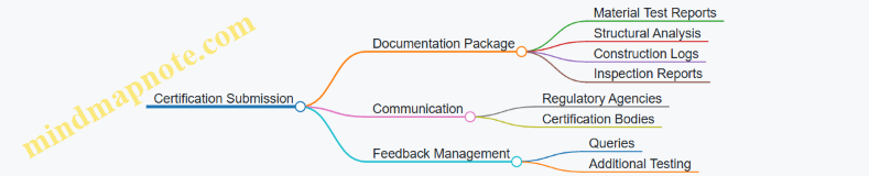
Example: The project received final certification approval after a comprehensive review, marking one of the first fully certified 3D printed commercial buildings in the region.
Summary of Best Practices
- Engage regulatory bodies early and maintain open communication.
- Rigorously test materials and structural designs before and during construction.
- Document every step of the printing and construction process meticulously.
- Use real-time monitoring technologies to ensure quality and environmental compliance.
- Collaborate closely with inspectors and certification agencies throughout the project lifecycle.
This example demonstrates that with thorough preparation, testing, and documentation, 3D printed commercial facilities can meet stringent certification requirements, paving the way for wider adoption of additive manufacturing in the construction industry.
9. Cost Analysis and Economic Feasibility
9.1 Cost Components in 3D Printed Construction Projects
Understanding the cost components involved in 3D printed construction projects is essential for construction engineers, project managers, and materials specialists to effectively budget, plan, and optimize resources. Unlike traditional construction methods, 3D printing introduces unique cost factors alongside conventional ones. This section breaks down these components with detailed explanations, mind maps, and practical examples.
Key Cost Components Overview
- Material Costs
- Equipment and Technology Costs
- Labor Costs
- Design and Engineering Costs
- Site Preparation and Setup Costs
- Maintenance and Operational Costs
- Quality Assurance and Testing Costs
- Contingency and Risk Management Costs
Mind Map: Cost Components in 3D Printed Construction
Material Costs
Materials form the backbone of any construction project. In 3D printing, the primary materials often include specially formulated concrete or mortar mixes, sometimes enhanced with additives for improved strength or faster curing.
Best Practice: Optimize material mix design to reduce waste and improve printability.
Example: A project printing a 100 m² wall used a concrete mix with 15% recycled aggregate, reducing raw material costs by 10% while maintaining structural integrity.
Equipment and Technology Costs
3D printers for construction are specialized and can be a significant upfront investment. Costs include purchase or lease, software licenses for design and printer operation, and ongoing maintenance.
Best Practice: Evaluate total cost of ownership including maintenance and software updates before procurement.
Example: Leasing a gantry-style 3D printer reduced initial capital expenditure by 40%, allowing the project to allocate more budget to materials and labor.
Labor Costs
While 3D printing reduces manual labor, skilled operators, engineers, and support staff are essential for setup, monitoring, and troubleshooting.
Best Practice: Train multi-disciplinary teams to optimize labor efficiency.
Example: Cross-training operators in both printer management and material preparation reduced labor hours by 15%.
Design and Engineering Costs
Designing for 3D printing requires specialized CAD modeling, structural analysis, and simulation to ensure print feasibility and safety.
Best Practice: Use integrated design platforms that allow iterative testing and optimization.
Example: A project using parametric design software reduced redesign cycles by 30%, saving time and associated costs.
Site Preparation and Setup Costs
Preparing the construction site for 3D printing involves groundwork, leveling, utilities setup, and safety measures tailored to the printer’s operational needs.
Best Practice: Conduct thorough site assessments to anticipate and mitigate setup challenges.
Example: Pre-installation of a modular foundation system expedited printer setup, cutting site preparation costs by 20%.
Maintenance and Operational Costs
Regular calibration, consumables replacement, and printer upkeep are ongoing expenses.
Best Practice: Implement preventive maintenance schedules to avoid costly downtime.
Example: Scheduled weekly calibration reduced printer errors by 25%, minimizing reprint costs.
Quality Assurance and Testing Costs
Testing printed materials and structures ensures compliance with safety and performance standards.
Best Practice: Integrate non-destructive testing methods to reduce inspection time and costs.
Example: Using ultrasonic testing on printed walls detected internal defects early, preventing costly structural failures.
Contingency and Risk Management Costs
Accounting for unexpected delays, material inconsistencies, or equipment failures is critical.
Best Practice: Allocate 10-15% of the budget for contingencies based on project complexity.
Example: A project with a 12% contingency fund successfully managed a two-week delay caused by supply chain disruptions without budget overruns.
Summary Table: Cost Components with Example Figures
| Cost Component | Description | Example Cost Estimate (USD) | Notes |
|---|---|---|---|
| Materials | Concrete, additives, reinforcements | $50,000 | Includes recycled materials savings |
| Equipment & Technology | Printer lease, software, maintenance | $70,000 | Leasing reduces upfront capital |
| Labor | Operators, engineers, support staff | $30,000 | Cross-training reduces hours |
| Design & Engineering | CAD, structural analysis, simulation | $15,000 | Parametric design reduces redesigns |
| Site Preparation | Groundwork, utilities, safety | $10,000 | Modular foundation accelerates setup |
| Maintenance & Operations | Calibration, consumables | $5,000 | Preventive maintenance reduces downtime |
| Quality Assurance | Testing and inspections | $8,000 | Non-destructive testing preferred |
| Contingency | Risk management | $18,000 | 12% contingency for unexpected issues |
Final Thoughts
Accurately understanding and managing these cost components enables project teams to leverage the benefits of 3D printing while maintaining financial control. Early integration of cost analysis in project planning helps identify opportunities for savings and risk mitigation.
For further insights, refer to section 9.5 for a detailed financial breakdown of a real-world 3D printed residential unit.
9.2 Comparing Traditional vs. 3D Printing Construction Costs
When evaluating construction methods, cost is a pivotal factor influencing decision-making. Comparing traditional construction costs with those of 3D printing reveals insights into efficiency, resource allocation, and long-term value.
Key Cost Components in Traditional Construction vs. 3D Printing
Labor Cost Comparison
- Traditional: High labor costs due to manual tasks, skilled trades, and extended project timelines.
- 3D Printing: Reduced labor needs; focus shifts to machine operation and supervision. Example: A 3D printed house in Mexico reduced labor costs by approximately 50% compared to traditional builds.
Material Cost Comparison
- Traditional: Bulk material purchase with potential overuse and wastage.
- 3D Printing: Precise material deposition reduces waste; however, specialized mixes may have higher unit costs.
Example: A project using 3D printed concrete optimized mix design to reduce cement content by 15%, lowering material costs despite higher additive expenses.
Equipment and Technology Costs
- Traditional: Equipment rental or purchase costs spread over multiple projects.
- 3D Printing: High initial investment in printers and software; however, automation reduces ongoing equipment needs.
Example: Deploying a gantry-based 3D printer on-site required upfront capital but reduced crane and scaffolding rental by 30%.
Time and Project Duration
- Traditional: Longer build times increase labor and overhead costs.
- 3D Printing: Accelerated construction reduces time-related expenses.
Example: A 3D printed office building was completed in 30% less time, saving on site management and financing costs.
Waste Management Costs
- Traditional: Significant waste disposal and recycling costs.
- 3D Printing: Minimal waste generation lowers disposal expenses.
Example: A 3D printed bridge project reported 70% less material waste, translating into substantial savings on waste handling.
Overhead and Indirect Costs
- Traditional: Includes permits, insurance, and site management.
- 3D Printing: Similar overheads but potential savings from reduced site activity and risk.
Summary Mind Map: Cost Advantages and Challenges
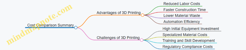
Integrated Example: Financial Breakdown of a 3D Printed Residential Unit vs. Traditional Build
| Cost Category | Traditional Build (USD) | 3D Printed Build (USD) | Notes |
|---|---|---|---|
| Labor | 40,000 | 20,000 | 50% reduction due to automation |
| Materials | 30,000 | 28,000 | Slightly lower due to optimized mixes |
| Equipment Rental | 15,000 | 25,000 | Higher upfront for 3D printer deployment |
| Time-Related Costs | 10,000 | 7,000 | Faster completion reduces overhead |
| Waste Management | 5,000 | 1,500 | Less waste generated |
| Overheads | 10,000 | 9,000 | Slight savings from reduced site activity |
| Total | 110,000 | 90,500 | ~18% overall cost savings with 3D printing |
Conclusion
While 3D printing in construction demands higher initial equipment and material innovation costs, the overall savings in labor, time, and waste management often result in a competitive or lower total project cost. For project managers and construction engineers, understanding these cost dynamics is crucial for effective budgeting and resource allocation.
For further reading, see section 9.5 for a detailed financial breakdown of a 3D printed residential unit.
9.3 Best Practices for Budgeting and Resource Allocation
Effective budgeting and resource allocation are critical to the success of any 3D printed construction project. Due to the novel nature of additive manufacturing in construction, careful planning can mitigate risks, control costs, and optimize resource use. Below is a detailed guide with mind maps and practical examples to help construction engineers, project managers, and materials specialists navigate this process.
Key Components of Budgeting in 3D Printed Construction
Example: A project manager for a 3D printed residential unit allocates 35% of the budget to materials, 25% to labor, 15% to equipment, 10% to design, 10% to site prep, and reserves 5% for contingencies. This distribution is based on prior project data and supplier quotes.
Mind Map: Resource Allocation Strategy
Example: A materials specialist negotiates bulk purchase discounts for specialized concrete additives, reducing costs by 12%. Simultaneously, the project manager schedules printer maintenance during low-activity periods to avoid downtime impacting critical printing phases.
Best Practices for Budgeting and Resource Allocation
-
Early Involvement of Cross-Functional Teams
- Engage engineers, project managers, and materials specialists from the start to accurately estimate costs and resource needs.
- Example: Collaborative workshops to define material specifications and printing parameters reduce redesign costs.
-
Detailed Cost Breakdown and Tracking
- Use project management software to track expenses against budget categories in real time.
- Example: Implementing a dashboard that flags when material costs exceed 80% of allocated budget.
-
Incorporate Contingency Buffers
- Allocate at least 5-10% of the budget for unforeseen issues like printer malfunctions or material inconsistencies.
- Example: A project encountered unexpected delays due to weather affecting site prep; contingency funds covered additional labor costs.
-
Optimize Material Usage
- Use design software to minimize waste by optimizing print paths and layer thickness.
- Example: Adjusting the print design reduced concrete usage by 15%, saving thousands in material costs.
-
Leverage Modular and Prefabricated Components
- Combine 3D printing with prefabrication to reduce on-site printing time and labor costs.
- Example: Printing modular wall sections off-site allowed parallel work streams, accelerating project completion.
-
Regular Resource Utilization Reviews
- Conduct weekly meetings to assess resource consumption and adjust allocations as needed.
- Example: Mid-project review identified underutilized equipment, enabling reallocation to other tasks.
-
Vendor and Supplier Management
- Establish strong relationships and contracts with multiple suppliers to ensure competitive pricing and supply security.
- Example: Dual sourcing of printing materials prevented project delays when one supplier faced shortages.
Mind Map: Budget Monitoring Workflow
Example: During a 3D printed bridge project, weekly budget reviews revealed rising labor costs due to overtime. The project manager adjusted the schedule to add shifts, reducing overtime and bringing labor costs back within budget.
Summary
Budgeting and resource allocation in 3D printed construction require a holistic, data-driven approach with continuous monitoring and flexibility. By integrating cross-disciplinary expertise, leveraging technology for tracking, and applying strategic resource management, projects can achieve cost efficiency and timely delivery.
For further reading, see section 9.5 “Financial Breakdown of a 3D Printed Residential Unit” for a detailed real-world example of budgeting and resource allocation in action.
9.4 Funding and Investment Opportunities in Construction 3D Printing
The rapid advancement of 3D printing technology in construction has opened numerous avenues for funding and investment. Understanding these opportunities is crucial for project managers, construction engineers, and materials specialists aiming to leverage financial resources effectively.
Types of Funding Sources
-
Government Grants and Subsidies
- Many governments worldwide are promoting innovative construction technologies through grants.
- Example: The U.S. Department of Energy’s funding for sustainable 3D printed housing projects.
-
Venture Capital (VC) and Private Equity (PE)
- Startups and companies developing 3D printing hardware, materials, and software attract VC investments.
- Example: ICON, a 3D printing construction startup, raised millions in VC funding to scale their technology.
-
Corporate Partnerships and Strategic Investors
- Large construction firms and material suppliers invest in 3D printing tech to stay competitive.
- Example: Caterpillar’s investment in 3D printing startups for heavy machinery parts.
-
Crowdfunding and Community Investment
- Smaller projects or pilot programs sometimes leverage crowdfunding to demonstrate proof of concept.
- Example: A community-funded 3D printed tiny home initiative.
-
Research and Development (R&D) Funds
- Universities and research institutions often receive dedicated R&D funds for additive manufacturing in construction.
Investment Focus Areas
-
Material Innovation
- Developing sustainable, high-performance printable materials.
- Example: Investments in geopolymer concrete startups that reduce carbon footprint.
-
Printer Hardware and Automation
- Enhancing printer scale, speed, and precision.
- Example: Funding robotic arm integration for complex architectural elements.
-
Software and Design Platforms
- CAD and simulation tools specialized for large-scale 3D printing.
- Example: Investment in AI-driven design optimization platforms.
-
Project Development and Construction Services
- Companies offering end-to-end 3D printed construction solutions.
- Example: Funding modular 3D printed housing projects in urban areas.
Mind Map: Funding and Investment Opportunities
Best Practices for Securing Funding
-
Develop a Clear Value Proposition
- Highlight cost savings, sustainability, and speed advantages.
- Example: Demonstrating 30% reduction in construction time through 3D printing.
-
Build Strong Partnerships
- Collaborate with academia, industry leaders, and government bodies.
- Example: Joint ventures between 3D printing firms and traditional construction companies.
-
Pilot Projects and Demonstrations
- Use small-scale projects to showcase feasibility and ROI.
- Example: 3D printed pedestrian bridges as proof of concept.
-
Leverage Intellectual Property (IP)
- Protect innovations to attract investors.
- Example: Patents on novel printable concrete mixtures.
-
Prepare Detailed Financial Models
- Include cost breakdowns, timelines, and risk assessments.
Example: Funding Journey of a 3D Printed Housing Startup
- Seed Funding
- Raised $500K via angel investors focusing on sustainable construction.
- Government Grant
- Secured $1M for R&D on eco-friendly printable materials.
- Series A VC Round
- $10M investment to scale printer manufacturing and pilot housing projects.
- Corporate Partnership
- Collaboration with a major construction firm for market entry.
This multi-source funding approach enabled rapid development and deployment of affordable 3D printed homes.
Mind Map: Best Practices for Funding Acquisition
Summary
Funding and investment in construction 3D printing are multifaceted, involving diverse sources and strategic focus areas. By understanding the landscape and adopting best practices, stakeholders can secure the necessary resources to innovate and scale large-scale additive manufacturing projects effectively.
9.5 Example: Financial Breakdown of a 3D Printed Residential Unit
In this section, we will explore a detailed financial breakdown of constructing a 3D printed residential unit. This example aims to provide construction engineers, project managers, and materials specialists with a clear understanding of cost components, savings, and economic feasibility.
Overview of the Project
- Project Type: Single-family residential unit
- Size: 120 square meters (approx. 1,292 square feet)
- Location: Urban setting with moderate labor costs
- Printing Technology: Large-scale gantry extrusion 3D printer
- Material: Specialized printable concrete mix
Mind Map: Major Cost Components
Detailed Cost Breakdown (USD)
| Cost Category | Description | Estimated Cost | Notes |
|---|---|---|---|
| Material Costs | Concrete mix, reinforcement, finishing | $12,000 | Concrete optimized for printability |
| Equipment Costs | Printer rental (30 days), maintenance | $8,000 | Includes setup and calibration |
| Labor Costs | Operators, engineers, finishing crew | $10,000 | Reduced labor compared to traditional |
| Site Preparation | Ground leveling, utilities | $4,000 | Standard site prep for residential build |
| Design and Planning | CAD modeling, structural engineering | $3,000 | Custom design for 3D printing |
| Quality Assurance | Material testing, structural inspections | $1,500 | Ensures compliance and safety |
| Contingency | Waste, delays, unforeseen expenses | $2,500 | 10% of total estimated cost |
| Total Estimated Cost | $41,000 |
Mind Map: Cost Savings Compared to Traditional Construction
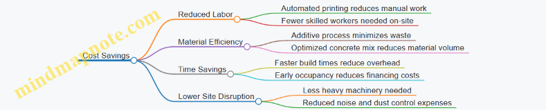
Example: Comparing Traditional vs. 3D Printed Construction Costs
| Cost Category | Traditional Construction | 3D Printed Construction | Savings (%) |
|---|---|---|---|
| Material Costs | $15,000 | $12,000 | 20% |
| Labor Costs | $20,000 | $10,000 | 50% |
| Equipment & Machinery | $6,000 | $8,000 | -33% (higher initial equipment cost) |
| Site Preparation | $5,000 | $4,000 | 20% |
| Design & Planning | $2,000 | $3,000 | -50% (more complex design) |
| Quality Assurance | $1,000 | $1,500 | -50% (more testing required) |
| Contingency | $3,000 | $2,500 | 17% |
| Total | $52,000 | $41,000 | 21% overall savings |
Best Practices to Optimize Financial Outcomes
- Material Optimization: Use locally sourced materials and tailor concrete mix for minimal waste.
- Efficient Printer Utilization: Maximize printer uptime by scheduling continuous prints and preventive maintenance.
- Labor Training: Cross-train operators to handle multiple roles, reducing labor costs.
- Design for Additive Manufacturing: Simplify designs to reduce print time and material usage.
- Contingency Planning: Allocate realistic contingency funds to avoid budget overruns.
Summary
This financial breakdown demonstrates that while some costs such as design complexity and equipment rental may be higher in 3D printed construction, significant savings in labor, materials, and time contribute to an overall cost reduction of approximately 20% compared to traditional methods. Project managers and engineers should leverage these insights to plan economically viable 3D printed residential projects.
Additional Resources
- 3D Printing Cost Calculator Tools
- Case Study: 3D Printed Homes in Mexico
- Material Cost Optimization Techniques
10. Future Trends and Innovations
10.1 Advances in Multi-Material and Multi-Scale Printing
In recent years, the construction industry has witnessed remarkable progress in multi-material and multi-scale 3D printing technologies. These advances enable the fabrication of complex, high-performance structures that combine different materials and operate at varying scales, from micro to macro, enhancing structural integrity, functionality, and sustainability.
What is Multi-Material and Multi-Scale Printing?
- Multi-Material Printing: The process of simultaneously or sequentially depositing two or more materials with distinct properties (e.g., concrete, polymers, metals) to create composite structures.
- Multi-Scale Printing: Fabrication that integrates features at different scales — microstructures for material performance and macrostructures for overall form and function.
Mind Map: Key Components of Multi-Material and Multi-Scale Printing
Advances in Materials
-
Concrete-Polymer Hybrids: Combining traditional concrete with polymer additives or fibers improves tensile strength and crack resistance. For example, printing a concrete shell with embedded polymer fibers enhances durability.
-
Metal-Infused Concrete: Incorporating metal powders or wires during printing allows for localized reinforcement and improved conductivity, useful for smart infrastructure.
-
Functionally Graded Materials (FGMs): Materials whose composition gradually changes over volume, enabling tailored mechanical properties. For example, a wall section printed with a gradient from dense concrete to lightweight foam for insulation.
Mind Map: Material Innovations
Advances in Printing Technologies
-
Multi-Nozzle Extrusion Printers: These printers use multiple print heads to deposit different materials simultaneously or in sequence, enabling complex composite layering.
-
Robotic Arm Systems: Flexible robotic arms equipped with interchangeable tools can print at multiple scales and deposit diverse materials with high precision.
-
Hybrid Printing: Combining additive manufacturing with subtractive processes (e.g., milling) allows for fine-scale detailing after coarse-scale printing.
Example: Multi-Material 3D Printed Pavilion
A recent project involved printing a pavilion structure using a multi-nozzle printer that deposited a high-strength concrete mixture for the main load-bearing elements and a lightweight insulating polymer for non-structural panels. This approach reduced overall weight by 30% while maintaining structural integrity.
Multi-Scale Printing Applications
-
Micro-Scale: Printing microstructures such as lattice infills or porous materials within walls to reduce weight and improve thermal performance.
-
Meso-Scale: Fabricating modular components with integrated channels for wiring or plumbing.
-
Macro-Scale: Constructing entire building shells or bridges with embedded multi-material layers for reinforcement and insulation.
Mind Map: Multi-Scale Printing Applications
Best Practices for Multi-Material and Multi-Scale Printing
-
Material Compatibility Testing: Conduct thorough tests to ensure bonding strength and chemical compatibility between materials.
-
Process Calibration: Synchronize print speeds and temperatures for different materials to avoid defects.
-
Design for Interface Zones: Engineer transition zones between materials to reduce stress concentrations.
-
Iterative Prototyping: Use small-scale prototypes to validate multi-material interactions before full-scale printing.
Example: Multi-Scale Reinforced Concrete Wall
A construction engineering team designed a 3D printed concrete wall with embedded fiber-reinforced polymer (FRP) micro-lattices at the micro-scale for crack resistance, meso-scale channels for electrical conduits, and macro-scale structural ribs for load distribution. This multi-scale approach improved durability and reduced construction time by 20%.
Summary
Advances in multi-material and multi-scale 3D printing are transforming construction by enabling the creation of smarter, stronger, and more sustainable structures. By integrating diverse materials and designing across scales, construction engineers, project managers, and materials specialists can unlock new possibilities for large-scale additive manufacturing projects.
10.2 Integration of AI and Machine Learning in Construction Printing
Artificial Intelligence (AI) and Machine Learning (ML) are revolutionizing the construction industry, particularly in the realm of 3D printing for large-scale structures. Their integration enhances precision, efficiency, and adaptability, enabling smarter decision-making and automation throughout the construction printing process.
Key Areas Where AI and ML Impact Construction 3D Printing
Design Optimization
AI-driven generative design tools allow engineers and architects to input design goals and constraints, and the AI generates multiple optimized design alternatives. This leads to structures that are lighter, stronger, and use less material.
Example: A project team used AI-powered generative design to create a 3D printed pedestrian bridge. The AI optimized the internal lattice structure, reducing concrete usage by 30% while maintaining structural integrity.
Process Automation and Real-Time Monitoring
Machine learning models analyze sensor data during printing to adjust parameters such as extrusion speed, layer thickness, and curing times in real-time. This adaptability helps mitigate issues caused by environmental changes or material inconsistencies.
Example: On a large-scale housing project, ML algorithms monitored temperature and humidity to dynamically adjust the concrete extrusion rate, preventing layer cracking and improving surface finish.
Quality Control and Defect Detection
Computer vision systems powered by AI inspect printed layers continuously, detecting defects like voids, delamination, or surface irregularities. Early detection allows immediate corrective actions, reducing waste and rework.
Example: A 3D printing firm implemented AI-based cameras that flagged anomalies during the printing of a commercial facility’s walls, enabling technicians to pause and recalibrate before defects propagated.
Predictive Maintenance
ML models predict when printing equipment might fail or require maintenance by analyzing operational data, minimizing downtime and extending machine lifespan.
Example: Predictive analytics alerted project managers to a potential nozzle clog in a gantry printer, allowing preemptive cleaning and avoiding a costly print failure.
Project Management Enhancements
AI tools assist project managers by forecasting project timelines, optimizing resource allocation, and assessing risks based on historical data and real-time inputs.
Example: An AI-driven dashboard provided real-time progress updates and predicted delays due to weather, enabling proactive schedule adjustments on a 3D printed bridge project.
Mind Map: AI & ML Workflow in Construction 3D Printing
Best Practices for Integrating AI and ML in Construction Printing
-
Start with Quality Data: Ensure sensors and data collection systems are calibrated and reliable to feed accurate data into AI models.
-
Collaborate Across Disciplines: Engineers, data scientists, and materials specialists should work together to tailor AI models to specific construction challenges.
-
Pilot and Iterate: Begin with small-scale pilot projects to validate AI-driven processes before full-scale deployment.
-
Maintain Human Oversight: Use AI as an augmentation tool rather than a replacement, keeping experts involved for critical decisions.
-
Invest in Training: Equip teams with the skills to interpret AI outputs and manage AI-enabled equipment.
Example: AI-Enhanced 3D Printing of a Modular Office Building
A construction company integrated AI-driven monitoring and control systems into their large-scale 3D printer for a modular office building project. The AI system continuously analyzed sensor data to adjust printing speed and material flow, compensating for changes in ambient temperature. Simultaneously, computer vision algorithms detected surface defects early, triggering immediate corrections. This integration reduced material waste by 15%, cut printing time by 20%, and improved overall build quality, demonstrating the tangible benefits of AI and ML in construction printing.
Conclusion
The integration of AI and Machine Learning in construction 3D printing is a transformative advancement that empowers construction engineers, project managers, and materials specialists to deliver smarter, faster, and more sustainable large-scale structures. By embracing these technologies and following best practices, the construction industry can unlock new levels of innovation and efficiency.
10.3 Potential for On-Demand and Remote Construction
The advent of 3D printing technology in construction has opened unprecedented opportunities for on-demand and remote construction projects. This capability is particularly transformative for locations that are difficult to access, disaster-stricken areas, and even extraterrestrial environments. Below, we explore the potential, challenges, and best practices associated with on-demand and remote construction enabled by 3D printing.
Key Advantages of On-Demand and Remote Construction
- Rapid Deployment: Structures can be printed quickly on-site without waiting for traditional supply chains.
- Reduced Logistics: Minimizes the need to transport bulky construction materials.
- Customization: Designs can be adapted in real-time to meet specific site conditions or client needs.
- Cost Efficiency: Cuts down labor and material waste.
- Sustainability: Enables use of local materials, reducing carbon footprint.
Mind Map: Core Components of On-Demand and Remote Construction
Examples of On-Demand and Remote Construction
-
Disaster Relief Housing in Indonesia
- After the 2018 earthquake, a mobile 3D printer was deployed to print emergency shelters directly on-site.
- Best Practice: Use of quick-setting, locally sourced concrete mix allowed rapid printing within 24 hours.
- Outcome: Reduced construction time by 60% compared to traditional methods.
-
Remote Arctic Research Station
- A 3D printer was transported to a remote Arctic site to build insulated living quarters.
- Best Practice: Integration of insulating materials within the printing mix improved thermal performance.
- Outcome: Enabled construction without heavy machinery, minimizing environmental disturbance.
-
Mars Habitat Prototype by NASA
- NASA’s 3D-Printed Habitat Challenge demonstrated on-demand construction using simulated Martian regolith.
- Best Practice: Use of autonomous robotic arms and AI for precision printing in remote, harsh conditions.
- Outcome: Validated feasibility of extraterrestrial on-demand construction.
Mind Map: Workflow for Remote 3D Printing Construction Projects
Best Practices for Successful On-Demand and Remote Construction
- Robust Remote Monitoring: Utilize IoT sensors and cloud platforms to track printing progress and environmental conditions.
- Modular Printer Design: Ensure printers can be easily disassembled, transported, and reassembled on-site.
- Material Adaptability: Develop printable materials tailored to local resources and climate conditions.
- Training & Collaboration: Prepare remote teams with thorough training and establish clear communication protocols.
- Redundancy Planning: Have backup systems for power, materials, and printer components to mitigate failures.
Summary
On-demand and remote construction using 3D printing is revolutionizing how and where we build. By leveraging mobile printing technologies, adaptable materials, and advanced digital tools, construction professionals can overcome traditional barriers of distance, logistics, and time. As this field evolves, embracing best practices and learning from pioneering projects will be key to unlocking its full potential.
10.4 Best Practices for Staying Ahead in a Rapidly Evolving Field
In the fast-paced world of 3D printing for construction and large-scale structures, staying ahead requires a proactive approach that combines continuous learning, strategic adoption of new technologies, and fostering collaboration across disciplines. Below are best practices designed specifically for construction engineers, project managers, and materials specialists to maintain a competitive edge.
Continuous Education and Skill Development
- Attend Industry Conferences & Workshops: Engage with events like the International Conference on 3D Printing in Construction (3DPC) to learn about the latest advancements.
- Online Courses & Certifications: Platforms such as Coursera and LinkedIn Learning offer specialized courses on additive manufacturing and construction technology.
- Cross-Disciplinary Training: Encourage knowledge exchange between engineers, materials scientists, and project managers to foster holistic understanding.
Example: A project manager enrolled in a certification program on robotic automation in construction, enabling better coordination with on-site 3D printing teams and improving workflow efficiency.
Early Adoption and Pilot Testing of Emerging Technologies
- Prototype and Pilot Projects: Implement small-scale pilot prints to evaluate new materials or printing techniques before full-scale deployment.
- Collaborate with Tech Developers: Partner with startups and research institutions to gain early access to cutting-edge printers and software.
Example: A materials specialist collaborated with a university lab to test a novel fiber-reinforced concrete mix, resulting in a 15% increase in tensile strength for printed walls.
Leveraging Data Analytics and AI
- Implement Real-Time Monitoring: Use sensors and IoT devices to collect data during printing for quality control and predictive maintenance.
- AI-Driven Design Optimization: Utilize machine learning algorithms to optimize structural designs for material efficiency and strength.
Example: An engineering team used AI software to simulate load distribution on a 3D printed bridge, reducing material use by 20% while maintaining safety standards.
Building a Collaborative Ecosystem
- Cross-Functional Teams: Create integrated teams combining expertise in design, materials, construction, and IT.
- Knowledge Sharing Platforms: Use internal wikis or cloud-based collaboration tools to document lessons learned and best practices.
Example: A construction firm established a digital knowledge hub where project managers and engineers shared real-time updates and troubleshooting tips during a 3D printed housing project.
Staying Informed on Regulatory Changes
- Regular Review of Codes and Standards: Monitor updates from bodies like ASTM International and local building authorities.
- Engage in Industry Advocacy: Participate in committees shaping regulations for 3D printed construction.
Example: A project manager contributed to a working group that developed safety guidelines for large-scale concrete extrusion printers, ensuring compliance and influencing policy.
Investing in Flexible and Scalable Infrastructure
- Modular Equipment: Choose printers and ancillary equipment that can be upgraded or reconfigured as technology evolves.
- Cloud-Based Software Solutions: Adopt platforms that allow seamless updates and integration with new tools.
Example: A construction company invested in a modular gantry 3D printer system that could be expanded to print larger structures without replacing the entire setup.
Mind Maps
Mind Map 1: Continuous Learning and Collaboration
Mind Map 2: Technology Adoption and Innovation
Mind Map 3: Regulatory and Strategic Engagement
By integrating these best practices, professionals in construction tech and additive manufacturing can not only keep pace with rapid advancements but also drive innovation that shapes the future of large-scale 3D printed structures.
10.5 Example: Conceptual Designs for Mars Habitat Using 3D Printing
The concept of establishing human habitats on Mars has captured the imagination of scientists, engineers, and futurists alike. 3D printing technology offers a revolutionary approach to constructing sustainable, efficient, and resilient habitats on the Red Planet. This section explores conceptual designs for Mars habitats using 3D printing, highlighting best practices, challenges, and innovative solutions.
Key Considerations for Mars Habitat Design
- Environmental Challenges: Extreme temperatures, radiation, dust storms, low gravity
- Material Constraints: Limited availability of Earth-based materials, reliance on in-situ resources
- Structural Requirements: Pressure containment, thermal insulation, radiation shielding
- Logistical Factors: Transport limitations, autonomous construction, repairability
Mind Map: Mars Habitat Design Factors
Best Practices in Mars Habitat 3D Printing Design
-
Utilize Local Materials (ISRU):
- Example: Using Martian regolith as a primary feedstock for the printing material reduces payload weight and cost.
- Practice: Develop binder materials compatible with regolith to create strong, durable composites.
-
Design for Autonomous Construction:
- Example: Robotic 3D printers capable of operating independently with minimal human intervention.
- Practice: Incorporate sensors and AI-driven feedback loops to adapt printing parameters in real-time.
-
Incorporate Multi-Layered Structures:
- Example: Outer layers printed with regolith-based concrete for radiation shielding; inner layers with insulating materials for thermal control.
- Practice: Use multi-material printing techniques to optimize habitat performance.
-
Modular and Expandable Design:
- Example: Habitat modules designed to interlock and expand as mission needs grow.
- Practice: Standardize connection interfaces to ensure compatibility and ease of assembly.
-
Redundancy and Repairability:
- Example: Design habitats with easily replaceable or repairable components using on-site 3D printing.
- Practice: Store raw materials and spare parts to enable quick repairs.
Example Conceptual Design: The “Red Haven” Mars Habitat
- Structure: Dome-shaped habitat printed using regolith-based concrete.
- Printing Method: Large-scale extrusion 3D printer mounted on a mobile robotic platform.
- Layers:
- Outer shell: Dense regolith concrete for radiation and micrometeorite protection.
- Middle layer: Insulating foam printed with polymer composites.
- Inner shell: Smooth polymer layer for airtightness and comfort.
- Features:
- Integrated airlocks printed as part of the structure.
- Embedded channels for water and power lines.
- Modular design allowing additional domes to be connected.
Mind Map: Red Haven Habitat Features
Additional Examples and Innovations
-
NASA’s 3D-Printed Habitat Challenge:
- Teams designed habitats using simulated Martian materials.
- Example: The SEArch+/Apis Cor design featured a curved, multi-chambered structure with integrated life support.
-
Contour Crafting:
- Large-scale extrusion printing technology that can print entire building shells autonomously.
- Application: Potential for rapid habitat construction on Mars using local materials.
-
Regolith Sintering:
- Using focused solar energy or microwaves to sinter regolith into solid bricks or layers.
- Example: Combining sintered bricks with 3D printed binders for hybrid construction.
Summary
3D printing for Mars habitats represents a convergence of advanced materials science, robotics, and architectural design. By leveraging in-situ resources, autonomous construction, and modular design principles, engineers and project managers can create viable living spaces that address the unique challenges of the Martian environment. These conceptual designs serve as blueprints for future missions and inspire ongoing innovation in additive manufacturing for extraterrestrial construction.
11. Comprehensive Case Studies
11.1 Large-Scale 3D Printed Bridges: Engineering and Execution
Introduction
Large-scale 3D printed bridges represent a transformative leap in construction technology, combining additive manufacturing with civil engineering to create durable, cost-effective, and innovative infrastructure solutions. This section explores the engineering principles, execution strategies, and best practices for successfully delivering 3D printed bridges.
Engineering Considerations for 3D Printed Bridges
Structural Design and Load Analysis
- Understanding load distribution in bridge spans
- Incorporating reinforcement strategies compatible with 3D printing
- Accounting for dynamic loads such as traffic and environmental forces
Material Selection
- Use of printable concrete mixes with enhanced tensile strength
- Integration of fiber reinforcement (e.g., basalt, carbon fibers) for durability
- Consideration of curing time and environmental resistance
Printing Technology and Equipment
- Selection of gantry or robotic arm printers based on bridge size and complexity
- Layer resolution and print speed trade-offs
- On-site vs. off-site printing and transportation logistics
Execution Workflow
-
Design Phase
- Utilize parametric CAD software tailored for additive manufacturing
- Simulate structural performance using finite element analysis (FEA)
- Optimize geometry for material efficiency and printability
-
Material Preparation
- Develop and test concrete/mortar mixes for extrusion consistency
- Quality control protocols for batch-to-batch uniformity
-
Site Preparation
- Leveling and stabilizing the printing platform
- Ensuring environmental controls (temperature, humidity) are within acceptable ranges
-
Printing Process
- Layer-by-layer extrusion with continuous monitoring
- Incorporation of reinforcement elements during printing
- Real-time adjustments based on sensor feedback
-
Post-Processing and Curing
- Controlled curing to achieve optimal strength
- Surface finishing and sealing for weather resistance
-
Testing and Certification
- Load testing under simulated real-world conditions
- Non-destructive evaluation (NDE) techniques to detect internal flaws
Best Practices
- Collaborative Planning: Engage structural engineers, materials specialists, and project managers early to align design and execution.
- Iterative Prototyping: Build scaled models or components to validate printing parameters and structural behavior.
- Continuous Monitoring: Use sensors and cameras to track print quality and detect defects immediately.
- Reinforcement Integration: Embed reinforcement materials during printing rather than post-printing for improved bonding.
- Environmental Adaptation: Adjust material mixes and printing schedules based on local climate conditions.
Mind Map: Engineering and Execution of 3D Printed Bridges
Example 1: The MX3D Stainless Steel Bridge (Amsterdam, Netherlands)
- Overview: A pioneering project using robotic arms to 3D print a stainless steel pedestrian bridge over a canal.
- Engineering Highlights: Complex geometry enabled by robotic printing; integration of sensors for structural health monitoring.
- Execution Insights: Printing occurred off-site with modular assembly on-site; extensive testing ensured safety and durability.
- Best Practice Demonstrated: Combining robotics with additive manufacturing to create complex, load-bearing structures.
Example 2: The 3D Printed Concrete Footbridge (TUM, Germany)
- Overview: A 3.5-meter concrete footbridge printed using a gantry system with integrated reinforcement.
- Engineering Highlights: Use of fiber-reinforced concrete mix; optimization of arch shape for load distribution.
- Execution Insights: On-site printing with real-time quality control; curing under controlled conditions.
- Best Practice Demonstrated: Material innovation and structural optimization for enhanced performance.
Example 3: The Canal House Project (Amsterdam, Netherlands)
- Overview: While primarily a building, the project included 3D printed structural components used in bridge-like applications.
- Engineering Highlights: Modular printing approach; hybrid construction combining traditional and additive methods.
- Execution Insights: Emphasis on sustainability and reduced material waste.
- Best Practice Demonstrated: Hybrid workflows to leverage strengths of both traditional and 3D printing methods.
Summary
Large-scale 3D printed bridges are at the forefront of construction innovation, requiring a multidisciplinary approach that integrates advanced materials, precise engineering, and meticulous execution. By following best practices and learning from pioneering projects, construction professionals can harness the full potential of additive manufacturing to build the bridges of the future.
Further Reading and Resources
- “Additive Manufacturing of Concrete Structures” – Journal of Construction Engineering
- MX3D Official Project Website: https://mx3d.com
- TUM Institute for Advanced Architecture of Catalonia (IAAC) Research Papers
11.2 Affordable Housing Solutions Using 3D Printing
Introduction
Affordable housing remains a critical global challenge, with millions of people lacking access to safe, durable, and cost-effective homes. 3D printing technology offers transformative potential by enabling rapid, customizable, and low-cost construction solutions. This section explores how 3D printing is leveraged to address affordable housing needs, highlighting best practices and real-world examples.
Mind Map: Affordable Housing Solutions Using 3D Printing
Cost Reduction
One of the primary advantages of 3D printing in affordable housing is the significant reduction in construction costs. By automating the layering process, labor costs decrease dramatically. Additionally, 3D printing minimizes material waste by precisely depositing concrete or composite materials only where needed.
Example: ICON, a construction technology company, demonstrated the cost-effectiveness of 3D printing by building a 350-square-foot home in Austin, Texas for under $10,000. This was achieved through optimized concrete mixes and streamlined printing processes.
Design Flexibility
3D printing allows for highly customizable designs without the need for expensive molds or formworks. This flexibility enables architects and engineers to create housing units tailored to specific community needs, including modular designs that can be expanded or reconfigured.
Example: Apis Cor developed a mobile 3D printer capable of printing an entire house on-site within 24 hours. Their designs incorporate integrated conduits for electrical wiring and plumbing, reducing post-printing installation time.
Sustainability
Affordable housing projects benefit from the sustainability potential of 3D printing. The technology supports the use of recycled materials such as construction waste or locally sourced aggregates. Energy-efficient designs can be incorporated directly into the printing process, such as optimized wall thickness and insulation channels.
Example: The New Story and ICON partnership focuses on building sustainable, 3D printed homes in regions with housing shortages. Their projects emphasize low carbon footprint materials and energy-efficient construction techniques.
Scalability
3D printing enables rapid construction, which is crucial for addressing housing shortages in disaster-stricken or rapidly urbanizing areas. Standardized printing protocols and modular designs allow for scalable deployment of affordable housing units.
Example: In Mexico, ICON printed a community of 3D printed homes in under a year, showcasing the scalability of this technology for mass housing.
Challenges
Despite its promise, 3D printing for affordable housing faces challenges such as navigating local building codes, ensuring material durability, and preparing sites for printing equipment.
Best Practice: Early engagement with regulatory bodies and thorough material testing can mitigate compliance risks. Additionally, site surveys and ground preparation must be integrated into project timelines.
Integrated Example: Building a 3D Printed Affordable Home
- Planning & Design: Collaborate with architects and engineers to develop a modular, energy-efficient design tailored to local climate and community needs.
- Material Selection: Use a concrete mix optimized for 3D printing with additives for faster curing and enhanced strength.
- Site Preparation: Level and prepare the site, ensuring stable ground and access for the printer.
- Printing Process: Deploy a gantry or robotic arm 3D printer to print walls layer-by-layer, integrating conduits for utilities.
- Post-Processing: Install roofing, windows, doors, and connect utilities.
- Quality Assurance: Conduct structural and safety inspections.
- Handover: Provide occupants with maintenance guidelines and warranty information.
Summary
3D printing is revolutionizing affordable housing by reducing costs, accelerating construction, and enabling sustainable, customizable designs. By adopting best practices and learning from pioneering projects, construction engineers, project managers, and materials specialists can harness this technology to address global housing challenges effectively.
11.3 Infrastructure Repair and Retrofitting with Additive Manufacturing
Additive manufacturing (AM), commonly known as 3D printing, is revolutionizing the way infrastructure repair and retrofitting are approached. Traditional repair methods often involve extensive downtime, high labor costs, and material wastage. By integrating 3D printing technologies, construction engineers, project managers, and materials specialists can achieve faster, more precise, and cost-effective repairs with enhanced durability.
Key Advantages of Using 3D Printing for Infrastructure Repair
- Precision and Customization: Ability to print complex geometries tailored to damaged areas.
- Reduced Downtime: On-site printing reduces the need for long shutdowns.
- Material Efficiency: Additive process minimizes waste compared to subtractive methods.
- Enhanced Durability: Use of advanced composite materials improves longevity.
Mind Map: Infrastructure Repair with Additive Manufacturing
Step-by-Step Best Practices for Repair and Retrofitting
-
Comprehensive Damage Assessment:
- Utilize drones and 3D scanning to create detailed models of damaged infrastructure.
- Employ ultrasonic or infrared NDT methods to detect subsurface defects.
-
Material Optimization:
- Select materials compatible with existing structures (e.g., polymer-modified concrete for flexibility).
- Adjust mix designs to ensure printability and structural performance.
-
Design Custom Repair Components:
- Use CAD software to design patches or replacement parts that fit precisely.
- Incorporate reinforcement fibers or meshes within printed layers for added strength.
-
On-Site Printing Setup:
- Deploy mobile or robotic 3D printers suited for the repair scale.
- Ensure environmental controls to maintain material curing and printer accuracy.
-
Printing and Monitoring:
- Monitor layer adhesion and dimensional accuracy in real-time.
- Adjust printing parameters dynamically to accommodate site conditions.
-
Post-Processing and Testing:
- Cure printed sections under controlled conditions.
- Conduct load and durability tests to validate repair quality.
Example 1: Bridge Deck Crack Repair Using 3D Printing
- Context: A highway bridge exhibited multiple longitudinal cracks reducing its load capacity.
- Approach: Engineers scanned the cracked areas and designed custom 3D printed polymer-modified mortar patches.
- Process: A robotic arm extruded the repair material directly into cracks, layer by layer.
- Outcome: The repair was completed in 48 hours with minimal traffic disruption, and follow-up testing showed restored structural integrity.
Example 2: Tunnel Lining Retrofitting
- Context: Aging tunnel linings required reinforcement to meet updated safety standards.
- Approach: Sections of the lining were 3D printed with fiber-reinforced concrete overlays using a gantry printer.
- Process: The printer was mounted inside the tunnel, printing directly onto existing surfaces.
- Outcome: The retrofit improved load distribution and extended the tunnel’s service life by 15 years.
Example 3: Historic Monument Restoration
- Context: A historic stone monument suffered erosion and partial structural failure.
- Approach: Using 3D scanning, missing or damaged stone elements were replicated with custom 3D printed composite materials mimicking original texture and strength.
- Process: Printed components were installed with minimal invasive procedures.
- Outcome: Restoration preserved the monument’s aesthetic and structural integrity while reducing restoration time by 40%.
Mind Map: Example Workflow for Infrastructure Repair
Summary
Additive manufacturing presents a transformative opportunity for infrastructure repair and retrofitting by enabling precise, efficient, and durable solutions. By following best practices—from thorough assessment and material optimization to on-site printing and rigorous testing—construction professionals can significantly enhance repair outcomes. The provided examples demonstrate real-world applications that highlight the versatility and effectiveness of 3D printing in extending the life and safety of critical infrastructure.
11.4 Modular and Prefabricated 3D Printed Components
Introduction
Modular and prefabricated components produced through 3D printing are revolutionizing construction by enabling faster assembly, improved quality control, and reduced waste. This approach allows construction engineers, project managers, and materials specialists to fabricate complex parts off-site or on-site, then assemble them efficiently into large-scale structures.
Benefits of Modular and Prefabricated 3D Printed Components
- Speed: Parallel fabrication and on-site assembly reduce overall project timelines.
- Quality Control: Controlled environment printing ensures consistent material properties.
- Customization: Complex geometries and tailored designs are achievable without additional tooling.
- Waste Reduction: Additive process minimizes material waste compared to subtractive methods.
- Logistics: Smaller modules simplify transportation and handling.
Mind Map: Key Aspects of Modular 3D Printed Components
Best Practices for Designing Modular 3D Printed Components
- Standardize Connection Points: Design uniform interfaces to ensure seamless assembly and interchangeability.
- Incorporate Tolerances: Account for printing and assembly tolerances to avoid fitment issues.
- Optimize for Printing Orientation: Align components to minimize support structures and maximize strength.
- Integrate Reinforcement: Embed fibers or steel reinforcements within modules for enhanced load-bearing capacity.
- Plan for Transportation: Design modules within size and weight limits for transport to the site.
Example 1: 3D Printed Modular Wall Panels
A construction company fabricated modular wall panels using a fiber-reinforced concrete mix printed off-site. Each panel included integrated channels for electrical wiring and plumbing. The panels were designed with tongue-and-groove joints to ensure tight fit and stability during assembly. This approach reduced on-site labor by 40% and improved thermal insulation performance.
Mind Map: Modular Wall Panel Features

Example 2: Prefabricated Structural Beams
A project utilized 3D printing to produce prefabricated beams with internal lattice structures for weight reduction without compromising strength. The beams were printed on-site using a gantry printer and assembled using mechanical fasteners. This modular approach enabled rapid erection of the building frame and facilitated future modifications.
Mind Map: Prefabricated Beam Characteristics
Integration of Modular Components into Large-Scale Structures
- Pre-Assembly Planning: Use BIM (Building Information Modeling) to simulate assembly sequences and detect clashes.
- On-Site Coordination: Synchronize deliveries and assembly teams to maintain workflow efficiency.
- Joint Sealing and Finishing: Apply appropriate sealants and surface treatments to ensure durability and aesthetics.
Challenges and Solutions
| Challenge | Solution |
|---|---|
| Alignment Precision | Use laser-guided positioning and adjustable joints |
| Weather Impact on Assembly | Schedule assembly during favorable conditions; use protective covers |
| Transportation Constraints | Design modules within transport limits; use modular sub-assemblies |
Summary
Modular and prefabricated 3D printed components offer transformative potential for construction projects by combining the flexibility of additive manufacturing with the efficiency of modular construction. By following best practices in design, fabrication, and assembly, construction professionals can leverage these components to deliver faster, cost-effective, and higher-quality structures.
Additional Resources
- BIM for Modular Construction
- Fiber Reinforced Concrete in 3D Printing
- Case Study: 3D Printed Modular Housing
11.5 Lessons Learned and Best Practices from Global Projects
3D printing in construction has rapidly evolved through numerous pioneering projects worldwide. These projects have provided invaluable insights, shaping best practices that construction engineers, project managers, and materials specialists can adopt to optimize outcomes. Below, we explore key lessons learned and best practices, supported by examples and mind maps to visualize the concepts.
Key Lessons Learned
Early and Continuous Collaboration
- Lesson: Successful projects emphasize early involvement of multidisciplinary teams — engineers, designers, material scientists, and site managers — to align expectations and technical feasibility.
- Example: The Dubai 3D Printed Office involved architects and engineers working closely from design to printing, enabling real-time adjustments and reducing rework.
Material Testing and Customization
- Lesson: Off-the-shelf materials rarely meet the unique demands of large-scale 3D printing; customized mixes and rigorous testing ensure structural integrity and printability.
- Example: The Apis Cor 3D printed house in Russia used a specially formulated concrete mix optimized for extrusion and rapid curing.
Site Preparation and Environmental Control
- Lesson: Environmental factors like temperature, humidity, and wind significantly impact print quality; controlled environments or protective measures are crucial.
- Example: The ICON 3D printed homes in Texas incorporated temporary shelters during printing to mitigate weather effects.
Real-Time Monitoring and Quality Assurance
- Lesson: Integrating sensors and cameras for live monitoring helps detect defects early, allowing immediate corrective actions.
- Example: The COBOD BOD2 printer used in multiple projects includes embedded sensors to monitor layer adhesion and material flow.
Regulatory Engagement and Documentation
- Lesson: Early engagement with local building authorities and thorough documentation streamline certification and compliance processes.
- Example: The 3D printed pedestrian bridge in Madrid was certified after collaborative testing and transparent reporting with regulators.
Best Practices Mind Map
Detailed Examples of Best Practices
Example 1: The BigDelta Bridge Project, The Netherlands
- Challenge: Printing a large pedestrian bridge with complex geometry and high load requirements.
- Best Practices Applied:
- Early collaboration between structural engineers and material scientists led to a concrete mix with enhanced tensile strength.
- Real-time monitoring detected minor layer inconsistencies, allowing immediate correction.
- Close regulatory engagement ensured the bridge met European safety standards.
- Outcome: The bridge was completed on time, withstanding rigorous load tests and serving as a model for future infrastructure projects.
Example 2: The 3D Printed Affordable Housing Initiative, Mexico
- Challenge: Rapidly constructing affordable homes in remote areas with limited infrastructure.
- Best Practices Applied:
- Customized, locally sourced materials reduced costs and environmental impact.
- Modular design allowed printing components off-site and assembly on-site, improving workflow efficiency.
- Project managers implemented strict quality assurance protocols to maintain structural safety.
- Outcome: Hundreds of homes were delivered faster and cheaper than traditional methods, improving community living standards.
Mind Map: Lessons Learned from Global Projects
Summary
The global experience with 3D printing for construction underscores the importance of a holistic approach: integrating technical innovation with collaborative project management and regulatory foresight. By adopting these lessons and best practices, construction professionals can harness the full potential of additive manufacturing to deliver safe, sustainable, and cost-effective large-scale structures.
12. Practical Guidelines and Checklists
12.1 Pre-Project Planning Checklist for 3D Printing Construction
Effective pre-project planning is critical to the success of any 3D printing construction project. This checklist guides construction engineers, project managers, and materials specialists through essential steps to ensure smooth execution, risk mitigation, and quality outcomes.
Mind Map: Pre-Project Planning Overview
Define Project Scope
- Objectives: Clearly outline what the 3D printed structure aims to achieve (e.g., residential housing, bridge, facade).
- Deliverables: Specify tangible outputs such as blueprints, printed components, and documentation.
- Constraints: Identify limitations like site size, budget, material availability, and timeline.
Example: For a 3D printed pedestrian bridge, the objective is to create a durable, lightweight structure spanning 10 meters within a 3-month timeline and a budget of $150,000.
Conduct Site Assessment
- Location Analysis: Evaluate soil type, topography, and climate.
- Accessibility: Ensure transport routes for equipment and materials.
- Environmental Conditions: Assess weather patterns and potential hazards.
Example: A construction site in a coastal area requires corrosion-resistant materials and scheduling prints during dry seasons to avoid humidity-related issues.
Prepare Design and Structural Plans
- Digital Model Finalization: Use BIM or CAD software to finalize the 3D model.
- Structural Analysis: Perform load and stress simulations.
- Material Selection: Choose materials compatible with printer capabilities and structural requirements.
Example: Designing a 3D printed wall with integrated channels for electrical wiring, ensuring structural integrity while accommodating utilities.
Select Equipment and Technology
- Printer Type: Choose between gantry, robotic arm, or crane-mounted printers based on project scale.
- Calibration & Testing: Schedule pre-print calibration runs.
- Backup Systems: Prepare contingency plans for equipment failure.
Example: Deploying a gantry-based printer for a multi-story building, with a backup power supply to prevent print interruptions.
Ensure Regulatory Compliance
- Building Codes: Verify that designs meet local and international standards.
- Permits: Obtain necessary construction and environmental permits.
- Safety Standards: Develop safety protocols for on-site printing operations.
Example: Securing a permit for a 3D printed commercial facility by demonstrating compliance with fire safety and structural codes.
Coordinate Project Team
- Roles & Responsibilities: Assign tasks to engineers, project managers, and materials specialists.
- Communication Plan: Establish regular meetings and reporting structures.
- Training: Provide 3D printing technology training to on-site personnel.
Example: Weekly coordination meetings to align design updates with printing schedules and material deliveries.
Develop Budget and Timeline
- Cost Estimation: Include materials, labor, equipment, and contingencies.
- Scheduling: Create a detailed timeline with milestones.
- Contingency Planning: Allocate buffer time and funds for unexpected delays.
Example: Budgeting an additional 10% for material wastage and a 2-week buffer for weather delays.
Implement Risk Management
- Identification: List potential risks such as printer malfunction, material defects, or regulatory delays.
- Mitigation Strategies: Develop action plans for each risk.
- Monitoring: Set up KPIs and regular risk reviews.
Example: Establishing a rapid response team to troubleshoot printer errors and maintain print quality.
Summary Checklist Table
| Step | Key Actions | Example Scenario |
|---|---|---|
| Project Scope | Define objectives, deliverables, constraints | 3D printed pedestrian bridge |
| Site Assessment | Analyze location, accessibility, environment | Coastal site with humidity considerations |
| Design Preparation | Finalize models, structural analysis, materials | Wall with embedded electrical channels |
| Equipment Selection | Choose printer, calibrate, backup plans | Gantry printer with backup power |
| Regulatory Compliance | Verify codes, obtain permits, safety protocols | Permit for commercial facility |
| Team Coordination | Assign roles, communication, training | Weekly multidisciplinary meetings |
| Budget & Timeline | Estimate costs, schedule, contingency | 10% material wastage budget, 2-week buffer |
| Risk Management | Identify, mitigate, monitor risks | Rapid response team for printer issues |
By following this comprehensive pre-project planning checklist, teams can anticipate challenges, optimize resource allocation, and ensure the successful deployment of 3D printing technology in construction projects.
12.2 Material Selection and Testing Protocols
Selecting the right materials and rigorously testing them are critical steps in ensuring the success, durability, and safety of 3D printed construction projects. This section provides a comprehensive guide on how construction engineers, project managers, and materials specialists can approach material selection and implement effective testing protocols tailored for large-scale additive manufacturing.
Material Selection Criteria
When choosing materials for 3D printing in construction, consider the following key factors:
- Structural Performance: Compressive strength, tensile strength, flexural strength, and elasticity.
- Printability: Flowability, setting time, extrusion compatibility, and layer adhesion.
- Durability: Resistance to environmental factors such as moisture, temperature fluctuations, UV exposure, and chemical attack.
- Sustainability: Use of recycled materials, low embodied energy, and environmental impact.
- Cost and Availability: Material cost, local sourcing, and supply chain reliability.
Mind Map: Material Selection Criteria
Common Materials Used in 3D Printing for Construction
- Concrete-based mixtures: Portland cement blends, geopolymer concrete, and fiber-reinforced concrete.
- Mortars and plasters: For finer detail or surface finishing.
- Composite materials: Combining concrete with polymers or fibers for enhanced properties.
- Specialty materials: Clay, recycled plastics, and bio-based materials.
Testing Protocols for Construction 3D Printing Materials
To ensure materials meet project requirements, the following testing protocols are recommended:
Fresh Material Testing
- Slump Test: Measures workability and flowability of concrete mixtures.
- Setting Time Test: Determines initial and final set times to optimize printing speed and layer bonding.
- Rheology Testing: Assesses viscosity and shear-thinning behavior critical for extrusion.
Hardened Material Testing
- Compressive Strength Test: Evaluates load-bearing capacity after curing.
- Flexural Strength Test: Measures resistance to bending stresses.
- Tensile Strength Test: Important for materials with fiber reinforcement.
- Durability Tests: Freeze-thaw cycles, water absorption, and chemical resistance.
Layer Adhesion and Bonding Tests
- Interlayer Shear Strength: Critical for structural integrity in layered printing.
- Microscopic Analysis: Visualizes bonding quality and porosity.
Long-Term Performance Testing
- Creep and Shrinkage Tests: Assess deformation over time.
- Environmental Exposure Tests: Simulate real-world conditions.
Mind Map: Material Testing Protocols
Best Practices for Material Testing
- Standardize Testing Procedures: Use ASTM or ISO standards adapted for 3D printing materials.
- Test Samples from Actual Prints: Avoid relying solely on lab-mixed samples; print test coupons under real conditions.
- Iterative Testing: Continuously refine material formulations based on test results.
- Cross-disciplinary Collaboration: Materials specialists should work closely with engineers and project managers to align material properties with structural and operational requirements.
Example: Optimizing a Concrete Mix for Large-Scale 3D Printing
Scenario: A project requires a concrete mix that balances fast setting time for rapid layer deposition with sufficient compressive strength for a multi-story structure.
Process:
- Initial Mix Design: Start with a standard Portland cement mix with added silica fume and polypropylene fibers.
- Fresh Material Testing: Conduct slump and rheology tests to ensure extrusion compatibility.
- Adjustments: Increase superplasticizer dosage to improve flowability without compromising strength.
- Setting Time Testing: Use admixtures to accelerate initial set time, enabling faster printing.
- Hardened Material Testing: Perform compressive strength tests at 7 and 28 days to verify structural requirements.
- Layer Adhesion Testing: Print sample walls and test interlayer shear strength.
- Iteration: Modify fiber content and admixture ratios based on test outcomes.
Outcome: Achieved a printable concrete mix with a 30-minute initial setting time, compressive strength exceeding 30 MPa at 28 days, and excellent interlayer bonding.
Summary
Material selection and testing protocols are foundational to the success of 3D printing in construction. By following structured criteria, employing rigorous testing, and iterating based on real-world data, project teams can ensure that materials not only meet technical specifications but also contribute to sustainable, cost-effective, and safe construction outcomes.
12.3 On-Site Setup and Safety Procedures
Setting up a 3D printing operation on a construction site involves meticulous planning, coordination, and adherence to safety standards to ensure smooth execution and protect all personnel involved. This section covers the essential steps and best practices for on-site setup and safety, supported by mind maps and practical examples.
Key Components of On-Site Setup
Detailed Breakdown
-
Site Preparation
- Ground Leveling: Ensure the printing area is flat and stable to support the printer’s weight and maintain dimensional accuracy.
- Accessibility: Clear pathways for material delivery, equipment movement, and emergency exits.
- Power Supply: Confirm availability of stable electrical sources; consider backup generators.
- Weather Protection: Use tents or enclosures to shield equipment and materials from rain, wind, or extreme temperatures.
-
Equipment Setup
- Printer Assembly: Follow manufacturer guidelines for assembling large-scale printers, including gantry systems or robotic arms.
- Calibration: Perform precise calibration of print heads, sensors, and movement axes to ensure print quality.
- Material Storage: Store printing materials in controlled environments to prevent contamination or degradation.
- Robotics Integration: Synchronize robotic components with the printer control system for automated workflows.
-
Workforce Coordination
- Roles Assignment: Define clear responsibilities for engineers, operators, safety officers, and material handlers.
- Training: Conduct hands-on training sessions emphasizing equipment operation and emergency response.
- Communication Protocols: Establish communication channels (e.g., radios, apps) for real-time updates and coordination.
-
Safety Measures
- Personal Protective Equipment (PPE): Mandatory use of helmets, gloves, eye protection, and respiratory masks as needed.
- Emergency Procedures: Prepare evacuation plans, first aid stations, and fire suppression equipment.
- Hazard Identification: Regularly inspect site for trip hazards, electrical risks, and material handling dangers.
- Safety Signage: Post clear signs indicating restricted zones, emergency exits, and equipment operation instructions.
Mind Map: Safety Procedures
Practical Example: Setting Up a 3D Printed Pavilion Project
Scenario: A project team is preparing to 3D print a large-scale pavilion structure on an urban site.
- Site Preparation: The team leveled the ground using laser-guided equipment and installed a temporary weatherproof canopy.
- Equipment Setup: The gantry-style 3D printer was assembled onsite, followed by a multi-point calibration process to ensure dimensional accuracy.
- Workforce Coordination: Roles were assigned with a dedicated safety officer monitoring compliance; daily briefings were held.
- Safety Measures: All workers wore PPE; clear signage marked the printer’s operational perimeter; emergency exits were mapped and rehearsed.
Outcome: The project completed the pavilion structure without any safety incidents, demonstrating the effectiveness of thorough on-site setup and safety protocols.
Additional Tips and Best Practices
- Conduct a pre-start safety meeting every day before printing begins.
- Use digital checklists to verify setup and safety compliance.
- Implement remote monitoring systems to reduce personnel exposure near moving parts.
- Schedule regular maintenance breaks to inspect equipment and replenish materials safely.
By integrating these on-site setup and safety procedures, construction teams can maximize the efficiency and safety of their 3D printing operations, ensuring successful project delivery and workforce well-being.
12.4 Post-Printing Inspection and Quality Assurance
Ensuring the quality and structural integrity of 3D printed construction elements is critical after the printing process is complete. Post-printing inspection and quality assurance (QA) protocols help identify defects, verify compliance with design specifications, and guarantee safety and durability.
Key Objectives of Post-Printing Inspection and QA
- Verify dimensional accuracy and geometric conformity
- Detect surface defects such as cracks, voids, or delamination
- Assess mechanical properties and material consistency
- Confirm adherence to regulatory and project-specific standards
Mind Map: Post-Printing Inspection and Quality Assurance Workflow
Visual Inspection
Visual inspection is the first and most straightforward step. It involves checking the printed structure for visible defects such as cracks, surface roughness, layer separation, or any anomalies.
Best Practices:
- Use high-resolution cameras and magnifying tools.
- Conduct inspections under varied lighting conditions.
- Document all findings with photos and notes.
Example: On a 3D printed concrete wall, inspectors identified minor surface cracks caused by rapid curing. Early detection allowed adjustment of the curing process for subsequent prints.
Dimensional Verification
Ensuring the printed structure matches the design dimensions is critical for structural fit and function.
Techniques:
- Laser Scanning: Creates a 3D point cloud to compare against CAD models.
- Photogrammetry: Uses multiple photographs to reconstruct 3D geometry.
- Manual Measurements: Calipers, tape measures for accessible areas.
Example: A 3D printed footbridge was scanned post-printing to verify that all components aligned within a 2mm tolerance, ensuring safe assembly.
Non-Destructive Testing (NDT)
NDT methods allow internal inspection without damaging the structure.
Common Methods:
- Ultrasonic Testing: Detects internal voids and delamination.
- Ground-Penetrating Radar (GPR): Maps internal features and reinforcement placement.
- Infrared Thermography: Identifies moisture intrusion or voids by thermal anomalies.
Example: Ultrasonic testing on a 3D printed retaining wall revealed internal voids near a joint, prompting targeted repairs before load testing.
Mechanical Testing
Mechanical tests confirm that the printed materials meet strength and durability requirements.
Tests Include:
- Compression testing for load-bearing capacity.
- Flexural strength testing for bending resistance.
- Hardness testing for surface durability.
Example: Samples extracted from a 3D printed housing unit underwent compression tests, confirming they exceeded minimum structural standards.
Documentation and Reporting
Comprehensive documentation ensures traceability and compliance.
Best Practices:
- Maintain detailed inspection logs with timestamps and inspector credentials.
- Generate compliance certificates aligned with local building codes.
- Record corrective actions and follow-up inspections.
Example: A 3D printed commercial facility project maintained a digital QA dashboard, enabling real-time tracking of inspection results and issue resolution.
Integrated Example: Post-Printing QA on a 3D Printed Bridge Segment
- Visual Inspection: Detected minor surface roughness; surface grinding planned.
- Dimensional Verification: Laser scan confirmed dimensional accuracy within 1.5mm.
- NDT: Ultrasonic testing found no internal defects.
- Mechanical Testing: Compression tests on sample coupons passed design criteria.
- Documentation: Inspection reports uploaded to project management system; no corrective actions required.
Summary
Post-printing inspection and quality assurance are essential to validate the safety, functionality, and longevity of 3D printed construction components. By combining visual checks, dimensional verification, advanced NDT methods, mechanical testing, and thorough documentation, construction teams can confidently deliver high-quality, reliable structures.
For construction engineers, project managers, and materials specialists, embedding these QA practices into workflows ensures that 3D printing technology fulfills its promise in transforming large-scale construction.
12.5 Maintenance and Lifecycle Management of 3D Printed Structures
Maintaining 3D printed structures and managing their lifecycle effectively is crucial to ensuring long-term durability, safety, and performance. Unlike traditional construction, 3D printed buildings and components often involve novel materials and design geometries, which require tailored maintenance strategies.
Key Aspects of Maintenance and Lifecycle Management
- Regular Inspection and Monitoring
- Preventive Maintenance
- Repair and Retrofitting
- Material Degradation Assessment
- Documentation and Data Management
- End-of-Life Considerations and Recycling
Regular Inspection and Monitoring
Routine inspections help detect early signs of wear, cracks, or material fatigue. Given the layered nature of 3D printed structures, monitoring should focus on both surface and internal integrity.
- Use of non-destructive testing (NDT) methods such as ultrasonic testing, infrared thermography, and ground-penetrating radar.
- Implementation of sensor networks embedded during printing for real-time structural health monitoring.
Example: A 3D printed pedestrian bridge in the Netherlands was equipped with embedded fiber optic sensors that continuously monitor strain and temperature, enabling proactive maintenance before visible damage occurs.
Preventive Maintenance
Preventive maintenance involves scheduled activities to prevent deterioration:
- Cleaning surfaces to prevent accumulation of debris or biological growth.
- Applying protective coatings to resist weathering and UV degradation.
- Monitoring and managing moisture ingress, especially in porous printed concrete.
Example: For a 3D printed residential wall, a water-repellent sealant was reapplied every two years to maintain waterproofing and prevent freeze-thaw damage.
Repair and Retrofitting
When damage occurs, repairs must be compatible with the original printed materials and structure:
- Use of compatible repair mortars or printable patches.
- Application of fiber-reinforced polymers (FRP) or carbon fiber wraps for strengthening.
- Retrofitting with embedded sensors or reinforcement elements to extend lifecycle.
Example: A 3D printed retaining wall in China was repaired using a custom-formulated printable concrete mix that matched the original material properties, ensuring structural continuity.
Material Degradation Assessment
Understanding how materials age under environmental stressors is critical:
- Regular sampling and laboratory testing of material cores.
- Monitoring for chemical changes such as carbonation or chloride ingress in concrete.
- Evaluating mechanical property changes over time.
Example: A research project on 3D printed concrete samples exposed to marine environments showed increased porosity after 5 years, guiding maintenance schedules for coastal structures.
Documentation and Data Management
Maintaining detailed records of printing parameters, materials used, inspection reports, and repairs is essential for lifecycle management.
- Use of Building Information Modeling (BIM) integrated with 3D printing data.
- Digital twins to simulate aging and predict maintenance needs.
Example: A commercial 3D printed office building uses a digital twin platform that tracks every maintenance activity, enabling predictive analytics for future upkeep.
End-of-Life Considerations and Recycling
Planning for the eventual decommissioning or repurposing of 3D printed structures supports sustainability:
- Designing for disassembly or modular replacement.
- Recycling printed materials or reusing aggregates.
- Assessing environmental impact of demolition waste.
Example: A 3D printed pavilion was designed with modular panels that could be detached and recycled into new printable material, reducing landfill waste.
Mind Maps
Mind Map 1: Maintenance Workflow for 3D Printed Structures
Mind Map 2: Material Lifecycle Considerations
Mind Map 3: Data Management in Lifecycle
Summary
Effective maintenance and lifecycle management of 3D printed construction structures require a multidisciplinary approach combining advanced monitoring technologies, tailored repair techniques, and comprehensive data management. By implementing these best practices, construction engineers, project managers, and materials specialists can ensure the longevity, safety, and sustainability of 3D printed buildings and infrastructure.
Additional Resources
- “Structural Health Monitoring of 3D Printed Concrete Bridges” – Journal of Construction Engineering
- “Repair Techniques for Additive Manufactured Concrete” – Materials Today
- “Digital Twins in Construction: Lifecycle Management” – Industry Whitepaper