Autonomous Construction Robotics for Smart Infrastructure
Chapter 1: Introduction to Autonomous Construction Robotics
1.1 Overview of Autonomous Robotics in Construction
Autonomous robotics in construction refers to machines capable of performing construction-related tasks with minimal human intervention. These robots combine sensors, control systems, and software to navigate, manipulate materials, and execute specific functions on construction sites. Their role is to improve efficiency, accuracy, and safety while reducing repetitive manual labor.
What Makes a Construction Robot Autonomous?
Autonomy in construction robotics involves several key capabilities:
- Perception: The robot senses its environment using cameras, LIDAR, GPS, or ultrasonic sensors.
- Decision-making: It processes sensor data to plan actions, such as navigating around obstacles or adjusting a task.
- Execution: The robot carries out physical tasks like digging, welding, or bricklaying.
These capabilities allow robots to operate with varying degrees of independence, from semi-autonomous (requiring some human input) to fully autonomous.
Mind Map: Core Components of Autonomous Construction Robotics
Types of Autonomous Construction Robots
Robots in construction come in various forms, each suited to specific tasks:
- Drones: Used for site surveying, inspection, and monitoring progress from the air.
- Ground Rovers: Mobile robots that can navigate terrain to perform tasks like material transport or earthmoving.
- Robotic Arms and Manipulators: Stationary or mobile arms that handle tasks such as welding, bricklaying, or concrete pouring.
Example: Autonomous Bricklaying Robot
A bricklaying robot can pick bricks, apply mortar, and place bricks with precision. It uses cameras and sensors to align bricks correctly and adjust for any irregularities. This reduces human fatigue and increases build speed while maintaining consistent quality.
Mind Map: Example Workflow of an Autonomous Bricklaying Robot
Why Use Autonomous Robots in Construction?
- Precision: Robots can place materials or perform tasks with millimeter accuracy.
- Safety: Robots can operate in hazardous environments, reducing risk to workers.
- Productivity: They can work continuously without fatigue, speeding up project timelines.
- Data Collection: Robots equipped with sensors gather data for quality control and project management.
Example: Drone-Based Site Surveying
Drones equipped with GPS and cameras fly over construction sites to create detailed 3D maps. These maps help project managers track progress and identify issues early. The drone autonomously follows pre-programmed flight paths and adjusts for weather or obstacles.
Mind Map: Drone Surveying Process
Challenges in Autonomous Construction Robotics
- Complex Environments: Construction sites are dynamic and cluttered, making navigation difficult.
- Variable Materials: Handling different materials requires adaptable grippers and control.
- Integration: Robots must work alongside humans and other machines safely.
- Reliability: Equipment must withstand harsh conditions and maintain performance.
Best Practice: Start with Semi-Autonomous Systems
Introducing robots that assist rather than replace human workers helps ease integration. For example, a robotic arm that assists with heavy lifting under human supervision can improve safety without requiring full autonomy.
In summary, autonomous construction robotics combine sensing, decision-making, and execution to perform tasks on construction sites. Their applications range from surveying and inspection to material handling and assembly. Understanding their components, capabilities, and challenges sets the foundation for deploying these systems effectively.
1.2 Key Components of Construction Robots
Construction robots are complex machines made up of several essential components that work together to perform tasks autonomously or semi-autonomously on construction sites. Understanding these components helps clarify how these robots operate and what makes them suitable for infrastructure projects.
Mechanical Structure
The mechanical structure forms the robot’s physical body. It includes the frame, joints, actuators, wheels or tracks, and any manipulators like arms or grippers. This structure must be robust enough to withstand harsh construction environments, including dust, vibration, and uneven terrain.
Example: An autonomous excavator uses a tracked base for stability on rough terrain and a hydraulic arm with multiple joints to dig and move soil precisely.
Sensors
Sensors provide the robot with information about its environment and its own state. Common sensors include:
- LIDAR: Measures distances to create 3D maps of surroundings.
- Cameras: Capture visual data for object recognition and navigation.
- Ultrasonic sensors: Detect nearby obstacles through sound waves.
- GPS: Provides location data for outdoor navigation.
- Inertial Measurement Units (IMU): Track orientation and movement.
Example: A drone inspecting a bridge uses cameras and LIDAR to detect cracks and structural issues while maintaining stable flight.
Control System
The control system is the robot’s brain. It processes sensor data, makes decisions, and sends commands to actuators. This system includes embedded processors, microcontrollers, and software algorithms for navigation, manipulation, and task execution.
Example: An autonomous concrete pouring robot uses control algorithms to adjust the flow rate and position of the nozzle based on real-time feedback.
Power Supply
Power systems provide the energy needed for movement, sensing, and computation. Construction robots may use batteries, fuel cells, or hybrid power sources. Power management is critical to ensure sufficient operation time and safety.
Example: A robotic bricklayer might use a high-capacity lithium-ion battery designed to last an entire work shift without recharging.
Communication Modules
Robots often need to communicate with human operators, other robots, or central control systems. Communication modules include Wi-Fi, cellular, radio frequency (RF), or wired connections.
Example: Multiple autonomous earthmoving machines coordinate their tasks via a dedicated radio network to avoid collisions and optimize workflow.
End Effectors
End effectors are the tools attached to the robot’s manipulators that interact with materials. These can be grippers, welding torches, drills, or concrete sprayers, depending on the task.
Example: A robotic arm equipped with a specialized gripper designed to handle irregularly shaped steel beams safely and securely.
Mind Map: Key Components of Construction Robots
Integration of Components
Each component must work seamlessly with the others. For example, sensors feed data to the control system, which then commands actuators to move the mechanical structure or operate end effectors. Power supply limitations can affect sensor usage and actuator performance, so energy-efficient design is important.
Example: In an autonomous road paving robot, GPS and LIDAR sensors map the site, the control system plans the path, actuators adjust the paving machine’s position, and the power system supports continuous operation.
Summary
Construction robots combine mechanical strength, sensory input, intelligent control, reliable power, communication capabilities, and task-specific tools. Each component plays a distinct role, and their integration enables the robot to perform complex infrastructure tasks with minimal human intervention.
1.3 Benefits of Automation in Infrastructure Building
Automation in infrastructure building brings a range of practical benefits that directly impact project efficiency, safety, and quality. Understanding these benefits helps clarify why autonomous construction robotics are becoming more common on job sites.
Increased Productivity
Robots can operate continuously without fatigue, unlike human workers who require breaks and shifts. This allows for longer operational hours and faster completion of repetitive or labor-intensive tasks. For example, an autonomous bricklaying robot can place thousands of bricks per day, maintaining consistent speed and accuracy.
Enhanced Precision and Quality
Robots follow programmed instructions with high accuracy, reducing human error. This precision is crucial in tasks like concrete pouring or steel placement, where small deviations can affect structural integrity. A concrete finishing robot, for instance, can ensure a uniform surface texture and thickness, improving durability.
Improved Safety
Construction sites are hazardous environments. Robots can take on dangerous tasks such as working at heights, handling heavy materials, or operating in confined spaces. Using drones for bridge inspection keeps human inspectors out of harm’s way while collecting detailed data.
Cost Efficiency
While initial investment in robotics can be high, automation often reduces labor costs and minimizes costly rework due to errors. Autonomous earthmoving machines can optimize fuel use and reduce material waste by precisely following grading plans.
Consistency and Reliability
Robots perform tasks uniformly every time, which helps maintain consistent quality across large infrastructure projects. This reliability is evident in automated welding robots that produce uniform welds, reducing weak points.
Data Collection and Monitoring
Many construction robots are equipped with sensors that gather real-time data on site conditions. This data supports better decision-making and project management. For example, autonomous inspection robots can detect cracks or corrosion early, allowing timely maintenance.
Flexibility in Task Execution
Modern construction robots can be reprogrammed or equipped with different tools to handle various tasks. A robotic arm might switch from rebar tying to material sorting, adapting to project needs without requiring new equipment.
Mind Map: Benefits of Automation in Infrastructure Building
Concrete Examples
-
Autonomous Excavators: These machines use GPS and sensors to follow precise excavation plans, reducing overdigging and material waste. This precision saves money and time while maintaining site safety by minimizing unexpected ground disturbances.
-
Robotic Bricklayers: By automating brick placement, these robots maintain consistent mortar application and alignment, speeding up wall construction while reducing manual labor injuries.
-
Inspection Drones: Equipped with high-resolution cameras and thermal sensors, drones inspect bridges and tunnels for structural issues faster and safer than manual inspections, providing detailed reports that help prioritize repairs.
-
Automated Concrete Pouring: Robots control the flow and distribution of concrete, ensuring even coverage and reducing the risk of weak spots. This leads to longer-lasting infrastructure and fewer costly repairs.
In summary, automation in infrastructure building offers tangible improvements in how projects are executed. It streamlines workflows, enhances safety, and delivers consistent quality, all while providing valuable data to guide ongoing operations.
1.4 Common Challenges and Solutions in Deploying Construction Robots
Deploying autonomous construction robots on infrastructure projects introduces a unique set of challenges. Understanding these hurdles and their practical solutions is essential for smooth integration and effective operation. Below, we explore common challenges, supported by mind maps and concrete examples.
Challenge 1: Navigating Complex and Dynamic Construction Sites
Construction sites are rarely static or uniform. Uneven terrain, moving equipment, changing layouts, and unpredictable obstacles complicate robot navigation.
Mind Map: Navigating Construction Sites
Example: An autonomous earthmoving robot uses LIDAR combined with stereo cameras to create a 3D map of its surroundings. When a crane moves unexpectedly into its path, the robot recalculates its route in real time, avoiding collision without halting operations.
Challenge 2: Ensuring Reliable Communication and Coordination
Construction sites often have limited connectivity, interference, and multiple robots operating simultaneously, which can disrupt communication.
Mind Map: Communication and Coordination
Example: A fleet of autonomous bricklaying robots communicates via a local mesh network. If one robot loses connection temporarily, it continues its current task independently and resynchronizes once the connection is restored, preventing downtime.
Challenge 3: Handling Variability in Materials and Construction Methods
Construction materials vary in size, shape, and texture. Robots must adapt to these differences to handle materials correctly and maintain quality.
Mind Map: Material Handling Variability
Example: A robotic arm equipped with tactile sensors adjusts its grip strength when picking up bricks of different sizes, preventing damage and ensuring precise placement.
Challenge 4: Integrating Robots with Existing Workflows and Human Teams
Robots must coexist with human workers and traditional equipment without causing delays or safety risks.
Mind Map: Integration with Workflows
Example: On a bridge construction site, autonomous welding robots operate during off-peak hours, while human workers perform preparatory tasks. Coordination meetings ensure smooth handoffs and avoid overlap.
Challenge 5: Maintaining Robot Reliability and Minimizing Downtime
Robots exposed to harsh construction environments face wear, sensor degradation, and unexpected failures.
Mind Map: Reliability and Maintenance
Example: A concrete pouring robot runs self-checks before each shift and alerts the maintenance team if sensor calibration drifts beyond acceptable limits, preventing quality issues.
Challenge 6: Ensuring Safety for All Site Personnel
Robots must operate safely around humans, avoiding accidents and minimizing risks.
Mind Map: Safety Considerations
Example: Autonomous inspection drones use infrared sensors to detect nearby workers and automatically maintain a safe distance, pausing operations if someone enters a restricted area.
Summary
Each challenge requires a combination of hardware, software, and operational strategies. Real-world examples demonstrate that practical solutions often involve layering multiple approaches—such as sensor fusion for navigation or mesh networks for communication—to build robust autonomous construction systems. Addressing these challenges early in deployment planning reduces surprises and improves project outcomes.
1.5 Best Practices: Selecting the Right Robot for Specific Infrastructure Tasks
Selecting the right robot for specific infrastructure tasks requires a clear understanding of the task requirements, site conditions, and robot capabilities. The goal is to match the robot’s strengths to the job’s demands, ensuring efficiency, safety, and quality. This section breaks down key considerations and offers practical examples to guide decision-making.
Key Considerations When Selecting Construction Robots
- Task Complexity: Is the task repetitive or variable? Simple repetitive tasks like bricklaying can use specialized robots, while complex tasks like structural assembly may require versatile manipulators.
- Environment: Indoor or outdoor? Confined spaces or open sites? Environmental factors affect robot size, mobility, and sensor needs.
- Payload and Reach: What materials or tools must the robot handle? Heavy loads require robust actuators; long reach is necessary for high or wide structures.
- Precision Requirements: Tasks like welding or rebar placement demand high positional accuracy, influencing sensor and control system choices.
- Mobility Needs: Does the robot need to navigate rough terrain or stairs? Wheeled, tracked, or legged robots each have pros and cons.
- Autonomy Level: Fully autonomous, semi-autonomous, or teleoperated? This depends on site complexity and safety protocols.
Mind Map: Factors Influencing Robot Selection
Matching Robots to Common Infrastructure Tasks
-
Earthmoving and Grading
- Requirements: Heavy payload, rough terrain mobility, moderate precision.
- Robot Type: Autonomous bulldozers or excavators with GPS and LIDAR.
- Example: An autonomous bulldozer equipped with RTK-GPS performs grading on a highway site, maintaining consistent slope with centimeter-level accuracy.
-
Material Handling and Transport
- Requirements: Payload capacity, navigation in cluttered sites.
- Robot Type: Wheeled transport robots with obstacle avoidance.
- Example: A wheeled robot autonomously moves pallets of bricks from storage to laying area, navigating around workers and equipment safely.
-
Bricklaying and Masonry
- Requirements: High precision, repetitive motion.
- Robot Type: Specialized robotic arms with end-effectors designed for brick placement.
- Example: A bricklaying robot uses vision systems to place bricks with millimeter accuracy, speeding up wall construction.
-
Inspection and Maintenance
- Requirements: Mobility in complex spaces, sensor payloads.
- Robot Type: Drones or climbing robots with cameras and ultrasonic sensors.
- Example: A drone inspects bridge undersides, capturing high-resolution images inaccessible to humans without scaffolding.
Mind Map: Robot Types and Suitable Tasks
Best Practices for Selection
- Define Clear Task Specifications: Write down exact task parameters including size, weight, precision, and environmental conditions.
- Evaluate Site Conditions: Conduct a site survey to understand terrain, obstacles, and space constraints.
- Assess Robot Capabilities Against Task Needs: Compare payload, reach, sensor suite, and autonomy level.
- Consider Integration and Compatibility: Ensure the robot can communicate with existing systems like BIM or site management software.
- Plan for Safety and Compliance: Verify that the robot meets safety standards and can operate safely around workers.
- Pilot Testing: Before full deployment, test the robot on a small scale to identify unforeseen issues.
Example Scenario
A city plans to automate the construction of a pedestrian bridge. The task involves:
- Transporting prefabricated components to the site.
- Assembling structural elements at height.
- Inspecting welds and joints.
Robot Selection Process:
- For transport: Wheeled robots with moderate payload capacity and obstacle avoidance.
- For assembly: Robotic arms with high precision and reach, mounted on mobile platforms.
- For inspection: Drones equipped with high-resolution cameras and thermal sensors.
This combination covers the full workflow efficiently while adapting to the site’s outdoor environment and height requirements.
Summary
Choosing the right robot is a balancing act between task demands, environment, and robot capabilities. Clear task definition, site understanding, and matching robot features to needs are essential. Using mind maps to visualize factors and options can help organize the decision process. Real-world examples show that no single robot fits all tasks; a mix tailored to specific jobs yields the best results.
1.6 Case Study: Successful Deployment of Autonomous Robots in Bridge Construction
Bridge construction is a complex process involving multiple stages such as site preparation, foundation laying, structural assembly, and finishing. Autonomous robots have been introduced to improve precision, safety, and efficiency in these stages. This case study examines a real-world example where a fleet of autonomous robots was deployed to build a medium-sized highway bridge.
Project Overview
The project involved constructing a 150-meter-long, two-lane concrete bridge over a river. The site presented challenges including uneven terrain, limited access, and tight scheduling. The construction team integrated autonomous robots to handle excavation, material transport, rebar placement, and concrete pouring.
Autonomous Robots Used
- Excavation Robot: An autonomous bulldozer equipped with GPS and LIDAR for earthmoving.
- Material Transport Robot: A rover capable of carrying heavy loads of rebar and concrete components.
- Rebar Placement Robot: A robotic arm mounted on a mobile platform for precise rebar assembly.
- Concrete Pouring Robot: A robotic arm with a nozzle for controlled concrete application.
Workflow and Coordination
The robots operated in a coordinated manner, with a central control system scheduling tasks and monitoring progress. The workflow included:
- Site grading and excavation by the bulldozer robot.
- Transport of rebar bundles and concrete components by the transport rover.
- Rebar assembly by the placement robot following structural plans.
- Concrete pouring and finishing by the pouring robot.
Mind Map: Bridge Construction Robot Workflow
Best Practices Applied
-
Pre-Deployment Calibration: Each robot underwent thorough calibration on-site to account for terrain irregularities and environmental factors. For example, the excavation robot’s GPS was fine-tuned to maintain grading accuracy within 5 cm.
-
Task Scheduling: The control system used priority-based scheduling to avoid bottlenecks. When the excavation robot finished a section, the transport robot was immediately dispatched to deliver materials, minimizing idle time.
-
Safety Protocols: Robots were equipped with proximity sensors to detect human workers and obstacles, automatically halting operations if necessary.
-
Data Feedback Loops: Real-time data from sensors was fed back to the control system, enabling dynamic adjustments. For instance, if the rebar placement robot detected misalignment, it paused and recalibrated before continuing.
Example: Rebar Placement Precision
The rebar placement robot used a combination of visual sensors and force feedback to position steel bars within millimeter tolerances. During one phase, it detected a slight deviation caused by uneven ground. The robot adjusted its arm trajectory and re-secured the rebar, ensuring structural integrity without human intervention.
Example: Concrete Pouring Control
The concrete pouring robot controlled flow rate and nozzle movement to prevent over-pouring or gaps. It adapted to weather conditions, slowing pour speed during windy periods to reduce splatter and maintain finish quality.
Outcomes
-
Time Savings: The autonomous fleet reduced overall construction time by approximately 20% compared to traditional methods.
-
Improved Accuracy: Structural components met design specifications with fewer errors, reducing rework.
-
Enhanced Safety: Fewer workers were exposed to hazardous tasks such as heavy lifting and working near machinery.
-
Cost Efficiency: Although initial investment was significant, operational costs decreased due to reduced labor and material waste.
Mind Map: Benefits and Challenges
This case demonstrates that autonomous robots can effectively handle multiple construction tasks when integrated thoughtfully. Key to success was the combination of precise hardware, adaptive software, and clear operational protocols. The example highlights how best practices in calibration, task scheduling, and safety can be woven into daily operations to achieve reliable outcomes.
Chapter 2: Robotics Hardware and Sensors for Construction
2.1 Types of Construction Robots: Drones, Rovers, and Manipulators
Construction robotics can be broadly categorized into three main types based on their form and function: drones, rovers, and manipulators. Each type serves distinct roles on a construction site, with specific strengths and limitations. Understanding these categories helps in selecting the right robot for the task at hand.
Drones
Drones, or unmanned aerial vehicles (UAVs), are flying robots equipped with cameras, sensors, and sometimes payload delivery systems. Their primary role in construction is site surveying, inspection, and monitoring.
- Functions: Aerial mapping, progress monitoring, safety inspections, and material transport over short distances.
- Advantages: Ability to access hard-to-reach areas, rapid data collection, and minimal disruption to site operations.
- Limitations: Limited payload capacity, battery life constraints, and sensitivity to weather conditions.
Example: A drone equipped with LIDAR sensors flies over a highway construction site to create a 3D terrain map. This map helps engineers verify earthwork progress without sending personnel into potentially hazardous zones.
Mind Map: Drones in Construction
Rovers
Rovers are ground-based mobile robots designed to navigate construction sites autonomously or semi-autonomously. They often carry sensors or tools to perform inspection, material transport, or earthmoving tasks.
- Functions: Terrain navigation, soil sampling, material hauling, and site inspection.
- Advantages: Can operate in rough terrain, carry heavier payloads than drones, and provide continuous operation with proper power sources.
- Limitations: Slower movement compared to aerial robots, potential obstacles requiring advanced navigation algorithms.
Example: An autonomous rover equipped with ground-penetrating radar surveys a construction site to detect underground utilities before excavation begins, reducing the risk of accidental damage.
Mind Map: Rovers in Construction
Manipulators
Manipulators are robotic arms or articulated machines designed to perform precise tasks such as assembly, welding, or material placement. They can be stationary or mounted on mobile platforms.
- Functions: Bricklaying, concrete pouring, welding, rebar tying, and component assembly.
- Advantages: High precision, repeatability, and ability to work in hazardous or confined spaces.
- Limitations: Limited mobility unless mounted on a mobile base, often require programmed instructions or human supervision.
Example: A robotic arm mounted on a tracked base lays bricks for a retaining wall, following a digital blueprint to ensure consistent spacing and alignment.
Mind Map: Manipulators in Construction
Summary Comparison
| Robot Type | Mobility | Payload Capacity | Typical Tasks | Strengths | Limitations |
|---|---|---|---|---|---|
| Drones | Aerial | Low | Surveying, inspection, monitoring | Fast data collection, access to high areas | Limited battery, payload, weather sensitivity |
| Rovers | Ground-based | Medium to High | Inspection, material transport, earthworks | Terrain adaptability, heavier payloads | Slower, obstacle navigation challenges |
| Manipulators | Stationary or mobile | Variable | Assembly, material placement, welding | Precision, repeatability | Limited mobility, programming complexity |
Each type of robot complements the others, often working together to cover the full range of construction activities. Selecting the right robot depends on the specific task requirements, site conditions, and integration with other systems.
2.2 Sensor Technologies: LIDAR, Cameras, Ultrasonic, and GPS
Sensors are the eyes and ears of autonomous construction robots. They gather data about the environment, enabling robots to navigate, avoid obstacles, and perform precise tasks. This section covers four key sensor types commonly used in construction robotics: LIDAR, cameras, ultrasonic sensors, and GPS.
LIDAR (Light Detection and Ranging)
LIDAR uses laser pulses to measure distances by calculating the time it takes for light to bounce back from surfaces. It creates detailed 3D maps of the surroundings, essential for navigation and obstacle detection.
- How it works: A laser emitter sends out pulses; a sensor detects reflections. The time delay translates into distance.
- Strengths: High accuracy, works well in various lighting conditions, generates precise point clouds.
- Limitations: Performance can degrade in heavy rain, fog, or dust; typically more expensive than other sensors.
Example:
An autonomous road inspection robot uses LIDAR to scan the road surface, detecting cracks and unevenness. The 3D map helps the robot adjust its path and focus inspection tools on problem areas.
Mind Map: LIDAR
Cameras
Cameras capture visual information, often in RGB (color) or infrared spectra. They provide rich contextual data, useful for object recognition, progress monitoring, and quality control.
- Types: Monocular, stereo, and multispectral cameras.
- Strengths: High-resolution imagery, color information, texture details.
- Limitations: Lighting-dependent, can struggle in low light or glare.
Example:
A bricklaying robot uses stereo cameras to estimate the distance to the wall and verify brick placement accuracy by comparing images against the design blueprint.
Mind Map: Cameras
Ultrasonic Sensors
Ultrasonic sensors emit high-frequency sound waves and measure the echo time to detect nearby objects. They are simple, cost-effective, and useful for short-range detection.
- How it works: Sound pulses travel until they hit an object and reflect back; the sensor calculates distance from the echo time.
- Strengths: Reliable in various lighting and weather conditions, inexpensive.
- Limitations: Limited range and resolution, affected by soft or angled surfaces that absorb or deflect sound.
Example:
An autonomous excavator uses ultrasonic sensors to maintain a safe distance from nearby equipment and workers, preventing collisions in tight spaces.
Mind Map: Ultrasonic Sensors
GPS (Global Positioning System)
GPS provides location data by receiving signals from satellites. It allows robots to determine their position on a construction site with reasonable accuracy.
- Strengths: Enables global positioning, useful for outdoor navigation and coordination.
- Limitations: Accuracy varies (typically within a few meters), signal can be blocked by structures or underground.
Example:
A fleet of autonomous bulldozers uses GPS coordinates to follow predefined grading paths, ensuring consistent earthmoving across a large site.
Mind Map: GPS
Summary
Each sensor type plays a distinct role in construction robotics. LIDAR excels at creating 3D maps; cameras provide rich visual context; ultrasonic sensors offer simple, reliable proximity detection; GPS supplies global positioning data. Combining these sensors allows robots to operate safely and effectively in complex construction environments.
Integrating sensor data through sensor fusion techniques enhances accuracy and robustness. For example, a robot might use GPS for rough positioning, LIDAR for obstacle mapping, cameras for detailed inspection, and ultrasonic sensors for close-range collision avoidance. Understanding the strengths and limitations of each sensor helps in designing systems that meet the specific demands of infrastructure projects.
2.3 Integration of Sensors for Real-Time Environment Mapping
Real-time environment mapping is the backbone of autonomous construction robotics. It allows robots to understand their surroundings, navigate safely, and perform tasks with precision. Integrating multiple sensors is essential because no single sensor can provide a complete picture of a dynamic construction site. This section explains how different sensors work together to create accurate, up-to-date maps and how this integration supports autonomous operations.
Why Sensor Integration Matters
Construction sites are complex environments with uneven terrain, moving equipment, and changing conditions. Relying on one sensor type can lead to gaps or errors. For example, cameras can struggle in poor lighting, while LIDAR might have difficulty with reflective surfaces. Combining data from various sensors compensates for individual weaknesses and improves reliability.
Core Sensors Used in Environment Mapping
- LIDAR (Light Detection and Ranging): Measures distance by bouncing laser pulses off surfaces, creating detailed 3D point clouds.
- Cameras (RGB and Depth): Capture visual information and depth data to identify objects and textures.
- Ultrasonic Sensors: Use sound waves to detect nearby obstacles, useful for close-range detection.
- GPS and GNSS: Provide global positioning data, essential for outdoor localization.
- IMU (Inertial Measurement Unit): Tracks orientation and motion, helping maintain accurate positioning when GPS signals are weak.
Steps in Sensor Integration for Mapping
- Data Acquisition: Sensors collect raw data simultaneously or in a coordinated sequence.
- Data Preprocessing: Noise reduction, calibration, and synchronization of sensor data streams.
- Sensor Fusion: Combining data from different sensors to form a unified representation.
- Map Generation: Creating 2D or 3D maps that represent the environment.
- Continuous Updating: Real-time adjustments to the map as the environment changes.
Mind Map: Sensor Integration Workflow
Sensor Fusion Techniques
-
Kalman Filter: A mathematical method that estimates the state of a system by combining noisy sensor data over time. It works well for linear systems and is often used to fuse GPS and IMU data.
-
Particle Filter: Handles non-linear and non-Gaussian problems by representing the probability distribution with particles. Useful for complex localization tasks.
-
Bayesian Networks: Probabilistic models that manage uncertainty and dependencies between sensor inputs.
Example: Combining LIDAR and Camera Data
Imagine an autonomous robot tasked with navigating a cluttered construction site. LIDAR provides a 3D point cloud showing obstacles, but it cannot identify what those obstacles are. Cameras add color and texture information, helping the robot distinguish between a stack of bricks and a moving worker.
The integration process involves aligning the camera images with the LIDAR point cloud, often through calibration and timestamp synchronization. This combined data allows the robot to build a semantic map, where objects are not just points but labeled entities. This improves decision-making, such as slowing down near workers or avoiding fragile materials.
Mind Map: Example of LIDAR-Camera Integration
Practical Considerations
-
Calibration: Regular calibration is necessary to maintain alignment between sensors. Even small shifts can cause mapping errors.
-
Latency: Sensor data must be processed quickly to keep maps current. High latency can lead to outdated maps and unsafe decisions.
-
Data Volume: Combining high-resolution sensors generates large amounts of data. Efficient compression and filtering techniques are needed to manage bandwidth and storage.
-
Environmental Factors: Dust, rain, and lighting changes affect sensor performance. Sensor fusion helps mitigate these issues by relying on complementary data.
Example: Ultrasonic and IMU Integration for Close-Range Navigation
In tight spaces, such as inside a tunnel under construction, GPS signals may be weak or unavailable. Here, ultrasonic sensors detect nearby walls and obstacles, while the IMU tracks the robot’s orientation and movement. By fusing these inputs, the robot maintains an accurate local map, enabling precise maneuvers without external positioning systems.
Mind Map: Ultrasonic-IMU Integration for Indoor Mapping
Summary
Integrating multiple sensors for real-time environment mapping is a practical necessity in autonomous construction robotics. Each sensor contributes unique strengths, and their combined data forms a reliable, detailed understanding of the site. This integration supports safer navigation, better task execution, and adaptability to changing conditions. Regular calibration, efficient data processing, and appropriate fusion algorithms are key to successful implementation.
2.4 Best Practices: Calibrating and Maintaining Sensors for Accuracy
Accurate sensor data is the backbone of autonomous construction robotics. Without reliable input, robots can misinterpret their environment, leading to errors, inefficiencies, or safety risks. Calibration and maintenance ensure sensors provide precise, consistent measurements over time.
Why Calibration Matters
Sensors drift due to temperature changes, mechanical wear, or environmental factors like dust and moisture. Calibration aligns sensor readings with known standards or reference points, correcting systematic errors.
Key Steps in Sensor Calibration
- Establish a Baseline: Use known reference objects or environments. For example, calibrate a LIDAR by scanning a flat wall at a fixed distance.
- Adjust Sensor Output: Modify sensor parameters or software offsets to match the reference.
- Validate Calibration: Test readings against multiple known points to confirm accuracy.
- Document Settings: Record calibration parameters for future reference and troubleshooting.
Mind Map: Sensor Calibration Process
Common Sensor Types and Calibration Examples
- LIDAR: Calibrate by scanning known flat surfaces and adjusting distance measurements. Example: A road inspection robot scans a concrete barrier; discrepancies in distance readings trigger recalibration.
- Cameras: Use checkerboard patterns to calibrate lens distortion and alignment. Example: A drone performing bridge inspection captures calibration images before flight to correct image distortion.
- Ultrasonic Sensors: Calibrate by measuring known distances in controlled settings. Example: An autonomous excavator uses ultrasonic sensors to detect proximity; periodic calibration ensures accurate obstacle detection.
- GPS Modules: Calibrate by comparing readings to fixed survey points. Example: A surveying robot cross-checks GPS data with ground truth markers to maintain positional accuracy.
Maintenance Practices to Preserve Sensor Accuracy
-
Regular Cleaning: Dust, mud, or debris can obscure sensors. Clean lenses, windows, and sensor surfaces with appropriate materials.
-
Environmental Protection: Use covers or housings to shield sensors from harsh conditions without blocking signals.
-
Firmware Updates: Keep sensor software up to date to fix bugs and improve performance.
-
Routine Checks: Schedule periodic sensor tests and recalibrations, especially after heavy use or impacts.
-
Redundancy and Cross-Checking: Use multiple sensors measuring the same parameter to detect anomalies.
Mind Map: Sensor Maintenance
Practical Example: Maintaining a Construction Drone’s Camera
A drone used for site inspection accumulates dust on its camera lens after several flights. The operator cleans the lens with a microfiber cloth before each flight. Weekly, the drone captures images of a calibration grid to adjust for any lens distortion. Firmware updates are applied monthly to improve image processing. This routine keeps the drone’s visual data reliable for mapping and defect detection.
Practical Example: Calibrating an Autonomous Excavator’s LIDAR
An autonomous excavator uses LIDAR to navigate and detect obstacles. After a day of operation in dusty conditions, the LIDAR readings start showing inconsistent distances. The maintenance team cleans the sensor window, then performs a calibration by scanning a known flat surface at a fixed distance. Software offsets are adjusted accordingly. The excavator resumes operation with restored accuracy.
Summary
Calibration and maintenance are ongoing commitments, not one-time tasks. They require clear procedures, proper tools, and documentation. By following these best practices, construction robots maintain the sensor accuracy necessary for safe and efficient autonomous operation.
2.5 Example: Using LIDAR-Equipped Robots for Road Surface Inspection
Using LIDAR-Equipped Robots for Road Surface Inspection
Road surface inspection is a critical task for maintaining infrastructure safety and longevity. Traditionally, this process involves manual surveys or vehicle-mounted sensors, which can be time-consuming, costly, and sometimes hazardous. Autonomous robots equipped with LIDAR (Light Detection and Ranging) sensors offer an efficient alternative by providing precise, high-resolution data while navigating complex road environments.
How LIDAR Works in Road Inspection
LIDAR sensors emit laser pulses and measure the time it takes for the light to reflect back from surfaces. This time-of-flight measurement creates a detailed 3D point cloud representing the road surface’s geometry. The data captures surface irregularities such as cracks, potholes, rutting, and unevenness.
Key Steps in Using LIDAR Robots for Road Inspection
- Deployment and Navigation: Robots autonomously traverse the road segment, using onboard GPS and inertial measurement units (IMUs) to maintain position.
- Data Acquisition: LIDAR sensors continuously scan the road surface, generating dense point clouds.
- Data Processing: Algorithms analyze the point clouds to detect surface defects and quantify their dimensions.
- Reporting: Inspection results are compiled into actionable reports for maintenance planning.
Mind Map: LIDAR-Based Road Inspection Workflow
Example: Autonomous Road Inspection Robot in Action
Consider a four-wheeled autonomous robot equipped with a 360-degree LIDAR sensor and high-precision GPS. The robot is programmed to inspect a 5-kilometer stretch of urban roadway.
- Navigation: The robot follows a pre-defined path, adjusting speed based on road conditions and obstacles.
- Scanning: The LIDAR sensor captures millions of data points per second, mapping the road surface in real-time.
- Defect Detection: Software algorithms process the point cloud to identify cracks wider than 3 mm and potholes deeper than 5 cm.
- Output: The system generates a map highlighting defect locations with severity scores, enabling targeted repairs.
Mind Map: Defect Detection Process
Practical Considerations and Best Practices
- Sensor Calibration: Regular calibration ensures LIDAR accuracy, especially after rough terrain traversal.
- Data Fusion: Combining LIDAR data with camera images can improve defect classification.
- Environmental Factors: Rain, fog, or dust can affect LIDAR performance; scheduling inspections during favorable conditions is advisable.
- Safety Protocols: Robots must detect and avoid pedestrians and vehicles, requiring robust obstacle detection.
Example: Integrating Camera and LIDAR Data
A robot uses synchronized LIDAR and RGB cameras. While LIDAR maps surface geometry, cameras capture texture and color, helping distinguish between surface materials and shadows that might confuse LIDAR alone. This fusion improves defect detection accuracy, especially for subtle cracks.
Mind Map: Sensor Fusion for Enhanced Inspection
In summary, LIDAR-equipped autonomous robots provide a reliable and efficient method for road surface inspection. Their ability to generate detailed 3D maps and detect defects with precision supports timely maintenance and infrastructure safety. Integrating best practices such as sensor calibration, data fusion, and environmental awareness enhances the effectiveness of these robotic systems.
2.6 Safety Considerations in Hardware Design and Deployment
Safety considerations in hardware design and deployment are fundamental to the successful use of autonomous construction robots. Construction sites are inherently risky environments, and adding robots introduces new challenges that must be addressed early in the design phase and throughout deployment.
Key Safety Aspects in Hardware Design
- Physical Robustness: Robots must withstand harsh site conditions such as dust, moisture, vibration, and impacts. Durable casings and shock-absorbing mounts protect sensitive components.
- Fail-Safe Mechanisms: Hardware should include emergency stop buttons, redundant power cutoffs, and mechanical brakes to halt operations instantly if needed.
- Collision Avoidance: Proximity sensors and bumpers help prevent accidental contact with humans, equipment, or structures.
- Ergonomic Design: Components that require human interaction, like control panels or maintenance access points, should be designed to minimize strain and error.
- Electrical Safety: Proper insulation, grounding, and protection against short circuits reduce risks of electrical hazards.
Deployment Safety Considerations
- Site Assessment: Before deploying robots, the site must be evaluated for hazards such as uneven terrain, overhead obstacles, and human traffic patterns.
- Clear Operating Zones: Defining and marking robot work areas keeps humans and machines safely separated.
- Communication Protocols: Robots should communicate their status clearly, using lights, sounds, or signals to alert nearby workers.
- Routine Inspections: Regular hardware checks detect wear or damage that could compromise safety.
Mind Map: Hardware Safety Design Elements
Mind Map: Deployment Safety Practices
Example 1: Emergency Stop Integration
A robotic excavator was designed with a large, red emergency stop button on its control panel and a wireless remote emergency stop accessible to site supervisors. During a test run, a worker accidentally entered the robot’s path. The supervisor immediately pressed the remote stop, halting the robot within milliseconds and avoiding injury. This example shows the importance of multiple fail-safe layers in hardware design.
Example 2: Proximity Sensors Preventing Collisions
In a deployment of autonomous material transport robots, proximity sensors were calibrated to detect humans within a 2-meter radius. When a worker approached, the robot automatically slowed down and stopped if the worker came closer. This setup reduced near-miss incidents significantly compared to earlier deployments without such sensors.
Example 3: Electrical Safety in Wet Conditions
A concrete spraying robot operated outdoors where rain was common. Its hardware included sealed connectors and waterproof enclosures rated for IP67. Additionally, all cables were routed away from puddles and grounded properly. This prevented electrical faults and ensured continuous operation despite adverse weather.
Summary
Designing and deploying construction robots requires a clear focus on safety at every step. Robust hardware, fail-safe features, and thoughtful deployment protocols work together to protect workers, equipment, and the project itself. Incorporating these safety considerations early reduces risks and builds trust in autonomous systems on construction sites.
Chapter 3: Software Architectures and Control Systems
3.1 Overview of Robot Operating Systems (ROS) in Construction Robotics
Robot Operating System (ROS) is a flexible framework for writing robot software. It provides a collection of tools, libraries, and conventions aimed at simplifying the task of creating complex and robust robot behavior across a wide variety of robotic platforms. In construction robotics, ROS plays a key role by offering a standardized way to manage hardware abstraction, device drivers, communication between processes, and package management.
What ROS Brings to Construction Robotics
Construction robots often operate in dynamic, unstructured environments. They need to integrate data from multiple sensors, execute precise control commands, and coordinate with other machines or human operators. ROS helps by:
- Modularizing software components: Developers can build reusable modules for perception, planning, control, and actuation.
- Facilitating communication: ROS uses a publish-subscribe messaging system that allows different parts of the robot’s software to exchange information asynchronously.
- Supporting simulation and visualization: Tools like RViz and Gazebo enable testing algorithms in virtual environments before deploying on real hardware.
- Providing hardware abstraction: ROS drivers standardize interaction with sensors and actuators, making it easier to swap components without rewriting code.
Core Concepts in ROS Relevant to Construction Robotics
- Nodes: Independent processes that perform computation. For example, one node might handle LIDAR data processing, another controls a robotic arm.
- Topics: Named buses over which nodes exchange messages. A sensor node might publish data on a topic that a navigation node subscribes to.
- Services: Synchronous remote procedure calls between nodes, useful for request-response interactions.
- Actions: For long-running tasks that provide feedback and can be preempted, such as moving a robot arm to a position.
Mind Map: Key ROS Components in Construction Robotics
Example: Using ROS for Autonomous Excavator Control
Consider an autonomous excavator tasked with digging a trench. The excavator uses multiple sensors: GPS for positioning, LIDAR for obstacle detection, and cameras for visual feedback. Each sensor runs a ROS node publishing data to relevant topics. A central planning node subscribes to these topics, processes the data, and sends commands to the excavator’s actuators via control nodes.
This setup allows developers to update or replace individual components without affecting the entire system. For instance, switching from one type of LIDAR sensor to another requires only updating the corresponding driver node.
Mind Map: Excavator ROS Node Interaction
Integration with Other Systems
ROS can integrate with Building Information Modeling (BIM) systems by exchanging data about site layouts and construction plans. This integration allows robots to align their tasks with project specifications, improving accuracy and coordination.
Summary
ROS provides a structured yet flexible environment for developing construction robotics software. Its modularity and communication mechanisms help manage the complexity of autonomous operations on construction sites. By using ROS, teams can build, test, and maintain robotic systems more efficiently, adapting to the diverse challenges of infrastructure building.
3.2 Path Planning and Navigation Algorithms
Path planning and navigation algorithms are the backbone of autonomous construction robotics. They enable robots to move efficiently and safely through complex, dynamic construction sites. This section breaks down the key concepts, common algorithms, and practical examples to help understand how robots find their way and avoid obstacles.
What is Path Planning?
Path planning is the process of determining a route from a start point to a goal point while avoiding obstacles. It involves two main components:
- Global Path Planning: Creating a route based on a known map or environment.
- Local Path Planning: Adjusting the route in real-time based on sensor data to avoid unexpected obstacles.
Navigation Algorithms Overview
Navigation algorithms combine path planning with control systems to move the robot along the planned path. They must handle uncertainties like moving equipment, uneven terrain, and changing site layouts.
Mind Map: Core Components of Path Planning and Navigation
Global Path Planning Algorithms
Dijkstra’s Algorithm is a classic graph search method that finds the shortest path between nodes in a weighted graph. It guarantees the shortest path but can be slow on large maps.
A* improves on Dijkstra by using heuristics to guide the search, making it faster while still finding an optimal path. For construction sites, A* is often used on grid maps representing the site layout.
Sampling-Based Methods like RRT and PRM are useful when the environment is high-dimensional or complex. They randomly sample points in the space to build a roadmap or tree, which the robot can follow.
Example: Using A* for Site Navigation
Imagine a robot tasked with moving materials across a site. The site is represented as a grid where each cell is either free or occupied by an obstacle. A* calculates the shortest path from the robot’s current location to the delivery point, avoiding blocked cells.
The heuristic might be the straight-line distance to the goal, which helps the algorithm prioritize paths closer to the target.
Local Path Planning and Obstacle Avoidance
Construction sites are dynamic. Equipment moves, workers walk around, and materials get shifted. Local path planning helps the robot react to these changes.
Dynamic Window Approach (DWA) evaluates possible velocities the robot can take in a short time window and selects the one that moves toward the goal while avoiding obstacles.
Vector Field Histogram (VFH) creates a histogram grid of obstacle density around the robot and chooses a direction with the least obstacles.
Example: Avoiding Unexpected Obstacles
A robot carrying concrete mixers encounters a suddenly parked vehicle blocking its path. Using LIDAR data, the local planner detects the obstacle and recalculates a short detour around it without stopping the entire operation.
Sensor Integration
Sensors provide the data needed for local planning and navigation. LIDAR offers precise distance measurements, cameras provide visual context, and ultrasonic sensors detect nearby objects.
Robots fuse this data to create a reliable map of their surroundings.
Mind Map: Sensor Roles in Navigation
Navigation Control
Once a path is planned, the robot must follow it. Control algorithms adjust the robot’s motors and steering to stay on course.
PID Controllers are common for smooth steering and speed control.
Model Predictive Control (MPC) considers future states and constraints to optimize movement, useful in uneven or slippery terrain.
Example: Steering Control on Uneven Terrain
An autonomous bulldozer uses MPC to adjust its speed and steering angle proactively, compensating for slopes and soft soil to maintain stability while following the planned path.
Summary
Path planning and navigation algorithms work together to help construction robots move efficiently and safely. Global planners chart the overall route, local planners handle immediate obstacles, sensors provide environmental data, and control systems execute the movement. Understanding these components and their interplay is essential for deploying robots that can handle the unpredictability of construction sites.
3.3 Control Systems for Manipulation and Material Handling
Control systems for manipulation and material handling in autonomous construction robotics govern how robots physically interact with materials and tools on site. These systems translate high-level commands into precise, coordinated movements of robotic arms, grippers, conveyors, or other end-effectors. The goal is to ensure safe, efficient, and accurate handling of construction materials, which vary widely in size, weight, and fragility.
Key Components of Control Systems
- Actuators: Motors and hydraulic or pneumatic devices that move joints and grippers.
- Sensors: Feedback devices such as force sensors, encoders, and cameras that inform the system about position, force, and environment.
- Controllers: Algorithms and hardware that process sensor data and send commands to actuators.
- End-effectors: Tools or grippers designed to hold, manipulate, or assemble materials.
Control Strategies
Control systems typically use a combination of the following strategies:
- Position Control: Commands the robot to reach a specific position or orientation. Useful for placing bricks or panels.
- Force Control: Regulates the force applied during manipulation, critical when handling fragile materials or during assembly.
- Hybrid Control: Combines position and force control to adapt to varying conditions, such as inserting a bolt while applying torque.
Mind Map: Control System Structure
Example 1: Robotic Bricklaying
In a bricklaying robot, the control system must position the robotic arm to pick up a brick, apply the correct amount of mortar, and place the brick with millimeter precision. Position control ensures the arm moves to the right coordinates, while force control prevents excessive pressure that could damage bricks or misalign the wall.
The system uses feedback from encoders to confirm arm position and force sensors on the gripper to monitor grip strength. If the force exceeds a threshold, the controller adjusts the grip to avoid crushing the brick.
Mind Map: Bricklaying Robot Control
Example 2: Autonomous Material Transport
Robots moving heavy construction materials like steel beams use control systems that coordinate multiple actuators for lifting and balancing. Force sensors detect uneven loads to adjust grip points dynamically. Position control guides the robot along planned paths, while force control ensures the load remains stable.
If the robot senses a sudden shift in weight distribution, the controller recalculates actuator commands to maintain balance and prevent dropping the load.
Mind Map: Material Transport Control
Coordination Between Manipulation and Mobility
In many construction robots, manipulation control systems must work closely with mobility controls. For example, a robotic arm mounted on a mobile platform must synchronize arm movements with platform positioning to avoid collisions and maintain stability.
Best Practices
- Sensor Fusion: Combine data from multiple sensors to improve accuracy and robustness.
- Redundancy: Use overlapping sensors or control methods to handle failures gracefully.
- Real-Time Feedback: Implement fast feedback loops to adjust control commands promptly.
- Modularity: Design control systems in modular layers to simplify updates and maintenance.
Summary
Control systems for manipulation and material handling translate commands into precise, adaptive actions. They rely on a mix of position and force control, sensor feedback, and actuator coordination. Examples like bricklaying and material transport illustrate how these systems ensure accuracy and safety in diverse construction tasks.
3.4 Best Practices: Implementing Robust Fail-Safe Mechanisms
Implementing robust fail-safe mechanisms in autonomous construction robotics is essential to ensure safety, reliability, and uninterrupted operation on complex construction sites. Fail-safe systems are designed to detect faults or unexpected conditions and respond in a way that prevents harm to people, equipment, or the environment. This section outlines practical approaches and examples to build such mechanisms effectively.
Understanding Fail-Safe Mechanisms
Fail-safe means that when something goes wrong, the system defaults to a safe state rather than continuing operation in a risky or uncontrolled manner. This can involve stopping the robot, switching to a backup system, or alerting human supervisors.
Key Elements of Fail-Safe Design
- Fault Detection: Identifying hardware or software errors quickly.
- Fault Isolation: Pinpointing the source of the problem to prevent cascading failures.
- Safe State Transition: Moving the robot to a predefined safe mode.
- Recovery Procedures: Steps to resume normal operation after the fault is resolved.
Mind Map: Fail-Safe Mechanism Components
Practical Best Practices
-
Redundancy in Critical Systems Use duplicate sensors or control units so if one fails, the other can take over. For example, a construction robot might have two independent LIDAR sensors; if one stops responding, the system switches to the other without halting work immediately.
-
Continuous Health Monitoring Implement real-time diagnostics that monitor motor currents, battery voltage, sensor outputs, and communication links. If any parameter drifts outside safe limits, trigger an alert or initiate a safe shutdown.
-
Graceful Degradation Design robots to reduce functionality rather than stop abruptly. For instance, if a robotic arm loses precision due to a joint sensor failure, it can switch to a slower, more cautious mode instead of continuing at full speed.
-
Clear Emergency Stop Protocols Equip robots with physical and remote emergency stop options. The robot should immediately cease movement and hold position safely when activated.
-
Fail-Safe Software Architecture Use watchdog timers and heartbeat signals between software modules. If a module stops responding, the system can reset it or switch to a backup.
-
Human-in-the-Loop Overrides Allow operators to intervene and take control when automated systems detect anomalies or when uncertain situations arise.
-
Regular Testing and Simulation Periodically test fail-safe responses under controlled conditions to verify that the robot behaves as expected during faults.
Example: Autonomous Excavator Emergency Stop
An autonomous excavator working on a highway project is equipped with multiple fail-safe features. It continuously monitors hydraulic pressure and motor temperatures. When a sensor detects abnormal pressure, the control system initiates a controlled stop, lowering the bucket safely to the ground. Simultaneously, an alert is sent to the operator’s control center. The excavator remains powered but immobilized until inspected and cleared.
Mind Map: Example - Excavator Fail-Safe Workflow
Example: Sensor Fusion for Navigation Fault Tolerance
A road-paving robot uses GPS, LIDAR, and inertial measurement units (IMUs) for navigation. If GPS signals degrade due to interference, the system detects the inconsistency by comparing sensor data. It then relies more heavily on LIDAR and IMU data to maintain accurate positioning. This redundancy prevents navigation errors that could lead to construction defects or safety hazards.
Mind Map: Sensor Fusion Fail-Safe
Summary
Robust fail-safe mechanisms rely on anticipating possible failures and designing systems that respond predictably and safely. Redundancy, continuous monitoring, graceful degradation, and clear protocols for emergency stops and human intervention form the core of effective fail-safe design. Real-world examples like autonomous excavators and sensor fusion in navigation illustrate how these principles work in practice. Regular testing and maintenance ensure these mechanisms remain reliable throughout the robot’s operational life.
3.5 Example: Autonomous Excavator Control Using Sensor Fusion
Autonomous excavators are a prime example of how sensor fusion improves precision and efficiency on construction sites. Sensor fusion refers to combining data from multiple sensors to create a more accurate understanding of the environment than any single sensor could provide alone. In the case of an autonomous excavator, this typically involves integrating inputs from GPS, LIDAR, cameras, inertial measurement units (IMUs), and sometimes ultrasonic sensors.
Why Sensor Fusion Matters for Excavators
Excavators operate in complex, dynamic environments. They must dig, lift, and move earth with precision, often near underground utilities or uneven terrain. Relying on a single sensor type can lead to errors: GPS signals may be weak or blocked, LIDAR can be confused by dust or rain, and cameras may struggle in low light. Sensor fusion mitigates these issues by cross-validating data and filling gaps.
Core Components in Sensor Fusion for Excavators
- GPS/RTK GPS: Provides global positioning with centimeter-level accuracy when using Real-Time Kinematic (RTK) corrections.
- LIDAR: Offers detailed 3D mapping of the immediate surroundings, detecting obstacles and terrain features.
- Cameras: Capture visual information for object recognition and terrain texture analysis.
- IMU: Measures acceleration and angular velocity to track the excavator’s orientation and movement.
- Ultrasonic Sensors: Detect close-range obstacles, useful for precise maneuvers.
How Sensor Fusion Works in Practice
The excavator’s control system collects raw data streams from each sensor. A fusion algorithm—often based on Kalman filters or particle filters—processes this data to estimate the excavator’s exact position, orientation, and the state of its environment. This integrated data informs the control commands for the boom, arm, and bucket.
Mind Map: Sensor Fusion Inputs and Outputs
Example Scenario: Digging a Trench
- Initial Survey: The excavator uses GPS and LIDAR to map the site and identify the trench boundaries.
- Positioning: Sensor fusion refines the excavator’s location to within centimeters, ensuring it stays on the planned path.
- Obstacle Avoidance: Cameras and LIDAR detect unexpected obstacles like rocks or pipes; the system adjusts the digging path accordingly.
- Arm Control: IMU data helps stabilize the arm and bucket movements, compensating for uneven terrain.
- Progress Monitoring: The fused sensor data tracks the depth and shape of the trench in real-time, allowing the system to correct deviations.
Mind Map: Autonomous Excavator Trench Digging Workflow
Practical Details
- Calibration: Sensors require regular calibration to maintain accuracy. For instance, LIDAR must be aligned with the excavator’s coordinate frame.
- Latency Management: Sensor data arrives at different rates; fusion algorithms must handle asynchronous inputs without lagging control responses.
- Robustness: The system should detect sensor failures and reconfigure to rely on remaining sensors.
Example of Sensor Fusion Algorithm Use
A common approach is the Extended Kalman Filter (EKF), which predicts the excavator’s state based on a motion model and updates it using sensor measurements. For example, the EKF might predict position changes from IMU data and correct those predictions with GPS and LIDAR readings.
Mind Map: Extended Kalman Filter in Excavator Control
Summary
Using sensor fusion in autonomous excavators improves accuracy and reliability by combining complementary sensor data. This approach enables precise digging, obstacle avoidance, and real-time progress tracking. The integration of multiple sensor types, combined with algorithms like the Extended Kalman Filter, forms the backbone of modern autonomous excavation systems.
3.6 Data Management and Communication Protocols on Construction Sites
Effective data management and communication protocols are essential for autonomous construction robotics to operate smoothly on site. Construction environments are dynamic, with multiple robots, human workers, and equipment interacting simultaneously. Without clear data flow and communication standards, robots can face delays, errors, or safety risks.
Key Aspects of Data Management
- Data Collection: Robots gather data from sensors, cameras, GPS, and other sources. This raw data must be organized and stored efficiently.
- Data Processing: Onboard or edge computing processes sensor inputs to make real-time decisions.
- Data Storage: Both temporary (cache) and long-term storage are necessary for operational continuity and historical analysis.
- Data Sharing: Robots and central control systems need to exchange information to coordinate tasks.
- Data Security: Protecting data integrity and preventing unauthorized access is critical.
Communication Protocols
Robots on construction sites use various communication protocols depending on range, bandwidth, and reliability requirements:
- Wi-Fi: Common for high-bandwidth data transfer within site boundaries.
- LTE/5G: Useful for remote monitoring or when site infrastructure is limited.
- Bluetooth: Short-range communication, often for peripheral devices.
- Zigbee/LoRa: Low-power, long-range protocols for sensor networks.
- Dedicated Short-Range Communications (DSRC): Sometimes used for vehicle-to-vehicle or vehicle-to-infrastructure communication.
Mind Map: Data Management Components
Mind Map: Communication Protocols
Example: Coordinating Multiple Robots for Road Paving
Imagine a team of autonomous pavers, rollers, and material delivery robots working together. Each robot collects data on its position, task progress, and environmental conditions. This data is shared over a Wi-Fi mesh network to a central control system that adjusts schedules and routes in real time.
- The paver robot sends updates on asphalt laying progress.
- The roller robot receives these updates and adjusts its speed accordingly.
- Material delivery robots use GPS and Wi-Fi to avoid collisions and ensure timely supply.
This coordination depends on reliable communication and structured data management to prevent delays or overlaps.
Best Practices
- Use Redundant Communication Channels: Combining Wi-Fi with LTE or mesh networks reduces downtime.
- Prioritize Data Types: Critical control commands should have higher priority over routine status updates.
- Implement Data Compression: To optimize bandwidth, especially for video or large sensor data.
- Secure Data Transmission: Use encryption and authentication to prevent tampering.
- Standardize Data Formats: Using common protocols like MQTT or ROS messages facilitates interoperability.
Example: Data Format Standardization
A robotic excavator and a surveying drone share terrain data. Both use a standardized JSON schema to represent coordinates, elevation, and soil type. This common format allows the excavator to adjust digging depth based on drone data without manual intervention.
Summary
Data management and communication protocols form the backbone of autonomous construction robotics. They enable robots to share information, coordinate tasks, and maintain safety on complex construction sites. Clear organization of data flow, reliable communication channels, and security measures ensure that robots can work effectively without human micromanagement.
Chapter 4: Autonomous Construction Task Planning and Execution
4.1 Task Decomposition for Infrastructure Projects
Task decomposition is the process of breaking down a large, complex infrastructure project into smaller, manageable tasks that autonomous construction robots can execute efficiently. This step is crucial because infrastructure projects often involve multiple phases, diverse activities, and various types of equipment. Clear task decomposition ensures that robots operate with precision, avoid conflicts, and contribute to overall project progress.
Why Task Decomposition Matters
Infrastructure projects such as building a bridge, road, or tunnel consist of numerous interdependent activities. Robots, unlike human workers, require explicit instructions and clear boundaries to perform their roles effectively. Decomposing tasks helps in:
- Defining clear objectives for each robot or robot team
- Scheduling tasks logically to avoid downtime or bottlenecks
- Allocating resources appropriately
- Monitoring progress and quality at granular levels
Steps in Task Decomposition
-
Identify Major Project Phases: Start by outlining the main phases of the project, such as site preparation, foundation work, structural assembly, finishing, and inspection.
-
Break Phases into Subtasks: Each phase is divided into smaller tasks. For example, site preparation might include clearing, grading, and soil compaction.
-
Define Task Dependencies: Understand which tasks must precede others. For example, foundation pouring cannot begin before excavation is complete.
-
Assign Tasks to Robots: Match tasks with the capabilities of available robots, considering their hardware, sensors, and software.
-
Establish Task Parameters: Specify details like location, timing, quality standards, and safety constraints.
Example: Road Construction Task Decomposition
Each of these tasks can be assigned to specialized robots. For instance, autonomous bulldozers handle grading, while paving robots manage asphalt laying.
Mind Map: Task Decomposition for a Bridge Construction
Best Practices in Task Decomposition
-
Granularity Balance: Tasks should be small enough for robots to handle but not so small that coordination becomes cumbersome.
-
Clear Interfaces: Define how tasks connect, especially when multiple robots are involved, to avoid overlap or gaps.
-
Flexibility: Allow for dynamic adjustment of tasks if site conditions change.
-
Documentation: Maintain clear records of task definitions and assignments for monitoring and troubleshooting.
Example: Task Decomposition for Tunnel Lining Installation
In this example, robots specialized in material handling transport and position segments, while inspection robots verify alignment and sealing.
Visualizing Task Dependencies
Understanding these dependencies helps schedule robot operations to maximize efficiency and avoid conflicts.
Summary
Task decomposition translates complex infrastructure projects into clear, actionable steps tailored for autonomous robots. It requires balancing detail with manageability, defining dependencies, and aligning tasks with robot capabilities. Using structured breakdowns and visual tools like mind maps helps project managers and engineers coordinate robotic efforts effectively.
4.2 Scheduling and Coordination of Multiple Robots
When multiple autonomous robots work together on a construction site, scheduling and coordination become essential to avoid conflicts, optimize efficiency, and maintain safety. Unlike a single robot operating independently, a fleet requires careful planning to manage task assignments, timing, and spatial interactions.
Key Concepts in Multi-Robot Scheduling
- Task Allocation: Assigning specific jobs to robots based on their capabilities and current status.
- Temporal Coordination: Planning the timing of tasks to avoid overlaps that could cause collisions or resource contention.
- Spatial Coordination: Managing robot positions and paths to prevent interference.
- Communication: Sharing status and intentions among robots to adapt to changes.
Mind Map: Multi-Robot Scheduling Components
Task Allocation Strategies
Task allocation can be centralized or decentralized. In centralized systems, a master controller assigns tasks based on a global view. In decentralized systems, robots negotiate among themselves.
Example: On a highway construction site, one robot is specialized in earthmoving, another in material transport, and a third in inspection. A centralized scheduler assigns the earthmoving robot to clear a section first, then schedules the transport robot to deliver materials, followed by the inspection robot verifying the work.
Temporal Coordination
Scheduling must consider task durations and dependencies. Some tasks cannot start until others finish.
Example: When installing tunnel lining, robots placing segments must wait for the excavation robot to clear the area. The scheduler ensures the lining robot’s task begins only after excavation completes, preventing idle time and collisions.
Spatial Coordination and Collision Avoidance
Robots share the same physical space, so their paths must be planned to avoid collisions. This involves defining work zones and dynamic path adjustments.
Example: In a bridge construction site, two robots working on opposite ends must avoid crossing paths simultaneously on narrow scaffolding. The system assigns time slots and alternate routes to keep them apart.
Mind Map: Coordination Challenges
Communication and Dynamic Replanning
Robots continuously exchange information about their status and environment. If a delay or obstacle occurs, the system replans tasks and paths.
Example: If a transport robot encounters debris blocking its route, it signals others and the scheduler reroutes it while reallocating tasks to maintain progress.
Practical Example: Coordinated Robot Team for Tunnel Lining Installation
- Robots Involved: Excavator, Segment Placement Robot, Inspection Drone
- Scheduling: Excavator clears a section, then segment robot installs lining, followed by inspection drone verifying quality.
- Coordination: Timing is critical; segment robot waits for excavation completion. Drone flies only after segment installation.
- Communication: Robots share progress updates; if excavation slows, segment robot adjusts start time.
Mind Map: Example Workflow
Best Practices
- Use clear task priorities and dependencies to avoid deadlocks.
- Incorporate buffer times to handle unexpected delays.
- Design communication protocols robust to signal interruptions.
- Implement real-time monitoring to detect and resolve conflicts quickly.
- Test scheduling algorithms in simulation before deployment.
Scheduling and coordination of multiple robots is a balancing act between efficiency and safety. By carefully assigning tasks, timing operations, and managing spatial interactions, construction projects can leverage robotic teams effectively without bottlenecks or accidents.
4.3 Adaptive Task Execution Based on Environmental Feedback
Adaptive task execution based on environmental feedback is a critical capability for autonomous construction robots. Construction sites are dynamic environments where conditions can change rapidly due to weather, unexpected obstacles, or variations in terrain. Robots that can adjust their actions in real time improve efficiency, safety, and quality of work.
Understanding Environmental Feedback
Environmental feedback refers to the continuous data that robots gather from their surroundings through sensors such as cameras, LIDAR, ultrasonic sensors, and force sensors. This data informs the robot about the current state of the environment, allowing it to detect changes or anomalies.
Core Components of Adaptive Execution
- Sensing: Gathering real-time data on terrain, obstacles, material conditions, and weather.
- Processing: Interpreting sensor data to identify deviations from the planned task or environment.
- Decision Making: Determining necessary adjustments to task parameters or strategies.
- Action: Implementing changes in robot behavior, such as altering speed, path, or tool operation.
Mind Map: Adaptive Task Execution Workflow
Example 1: Autonomous Excavator Adjusting to Soil Variability
An autonomous excavator is tasked with digging a trench. Sensors detect that the soil is harder than expected in a certain section. The robot processes this feedback and decides to reduce the digging speed and increase the force applied by the arm. It also adjusts the digging angle to optimize penetration. This adaptation prevents tool damage and maintains progress without human intervention.
Example 2: Robot Navigating Around Unexpected Obstacles
A transport robot carrying materials encounters debris blocking its planned path. Using LIDAR and camera data, it identifies the obstacle and recalculates an alternative route around it. The robot communicates the change to other robots on site to avoid conflicts. This dynamic path replanning keeps the workflow smooth.
Mind Map: Environmental Feedback Types and Responses
Best Practices for Implementing Adaptive Execution
- Robust Sensor Fusion: Combine multiple sensor inputs to improve reliability and reduce false positives.
- Real-Time Data Processing: Use edge computing to minimize latency between sensing and action.
- Modular Decision Framework: Separate decision logic into modules for easier updates and maintenance.
- Fail-Safe Defaults: Define safe fallback behaviors if sensor data is ambiguous or lost.
- Continuous Learning: Incorporate feedback loops to refine decision rules based on past performance.
Example 3: Coordinated Robot Team Handling Weather Changes
On a rainy day, a team of robots working on a road project detects increased surface moisture. The robots adapt by reducing speed to avoid slippage and delay concrete pouring until conditions improve. The system also alerts human supervisors. This coordination minimizes risks related to weather.
Summary
Adaptive task execution allows construction robots to respond intelligently to real-world conditions. By integrating sensing, processing, decision-making, and action, robots maintain productivity and safety despite environmental variability. Practical examples show how these adaptations work in excavation, navigation, and weather response, highlighting the importance of flexible autonomy on construction sites.
4.4 Best Practices: Dynamic Replanning to Handle Site Variability
Dynamic replanning is essential in autonomous construction robotics because construction sites rarely stay static. Changes in terrain, unexpected obstacles, weather conditions, or shifting priorities require robots to adjust their plans on the fly. This section outlines best practices for implementing dynamic replanning to maintain efficiency and safety.
Understanding Dynamic Replanning
Dynamic replanning means that a robot’s task plan is not fixed but can be updated continuously or at discrete intervals based on new data. This flexibility helps robots respond to real-world variability without human intervention.
Key Elements of Dynamic Replanning
Best Practices
1. Continuous Environment Monitoring Robots should constantly gather data from sensors like LIDAR, cameras, and GPS to detect changes such as new obstacles or terrain shifts. For example, an autonomous excavator might detect a previously unknown underground pipe and adjust its digging path accordingly.
2. Modular Task Planning Breaking down tasks into smaller, independent modules allows easier replanning. If a robot encounters an obstacle during a task, it can pause that module, replan, and then resume or switch to a different task. For instance, a robot laying concrete can stop pouring in one section and move to another while avoiding a detected hazard.
3. Prioritize Safety and Compliance When replanning, safety constraints must override efficiency. If a robot detects a human worker nearby, it should immediately replan to maintain safe distances, even if it means delaying the task.
4. Use Predictive Models Incorporate predictive analytics to anticipate site changes, such as soil instability after rain. This helps the robot proactively adjust plans rather than reactively.
5. Efficient Path Re-Optimization Employ algorithms like A* or D* Lite for quick path recalculations. For example, if a delivery robot’s original route is blocked by construction debris, it can find an alternative path without stopping operations.
6. Task Reallocation Among Robot Teams In multi-robot scenarios, if one robot encounters an issue, tasks can be dynamically reassigned. For example, if a drone cannot inspect a section due to weather, a ground robot might take over.
7. Smooth Task Transitions Ensure that replanning does not cause abrupt stops or starts. Gradual deceleration and acceleration help maintain mechanical integrity and operational flow.
8. Robust Error Detection and Recovery Implement mechanisms to detect when replanning fails or leads to dead ends, triggering fallback plans or human alerts.
Mind Map: Dynamic Replanning Workflow
Example 1: Autonomous Road Paving Robot
A road paving robot encounters unexpected underground cables not marked on the site map. Its sensors detect the cables, triggering a replanning routine. The robot recalculates its path to avoid the cables, adjusts its paving sequence, and communicates with other robots to shift their tasks accordingly. This prevents damage and downtime without human intervention.
Example 2: Tunnel Lining Installation
During tunnel lining, an autonomous robot detects a section where the rock face is unstable. It pauses work, replans to focus on reinforcing safer sections first, and alerts the control center. Meanwhile, other robots adjust their tasks to maintain overall project progress.
Mind Map: Example Scenario - Tunnel Lining Replanning
Dynamic replanning is not just about changing routes; it involves a holistic approach to sensing, decision-making, task management, and communication. Following these best practices helps autonomous construction robots handle the unpredictable nature of construction sites while maintaining productivity and safety.
4.5 Example: Coordinated Robot Teams for Tunnel Lining Installation
Coordinated robot teams for tunnel lining installation represent a practical application of autonomous construction robotics where multiple machines work together to complete complex tasks efficiently and safely. Tunnel lining involves placing precast concrete segments or spraying concrete (shotcrete) to stabilize the tunnel walls. This task requires precision, timing, and adaptability to the tunnel’s shape and conditions. Using a team of robots can improve consistency, reduce human exposure to hazardous environments, and speed up the process.
Overview of Coordinated Robot Teams in Tunnel Lining
- Multiple robots perform specialized roles simultaneously.
- Communication and synchronization are key to avoid collisions and ensure smooth workflow.
- Tasks include segment delivery, positioning, fastening, and surface finishing.
Mind Map: Roles in a Coordinated Robot Team for Tunnel Lining
Example Scenario: Tunnel Lining Installation
Imagine a tunnel boring machine (TBM) has just completed a section of excavation. The lining installation team of robots moves in immediately. Segment transport robots bring precast concrete rings from a staging area inside the tunnel. Positioning robots receive these segments, use laser scanners and inertial measurement units (IMUs) to align each segment with millimeter precision. Fastening robots then secure the segments using hydraulic bolts. Finally, surface finishing robots spray shotcrete to seal gaps and smooth the surface.
Mind Map: Workflow Sequence
Best Practices in Coordinated Robot Teams
-
Clear Task Division: Each robot should have a well-defined role to prevent overlap and confusion. For example, transport robots focus solely on moving segments, while positioning robots handle alignment.
-
Robust Communication Protocols: Use reliable wireless communication with fail-safes to maintain coordination. A supervisory system can manage task queues and robot status.
-
Real-Time Sensor Feedback: Robots should continuously gather data about their position, the tunnel environment, and segment placement to adjust actions dynamically.
-
Collision Avoidance: Implement spatial awareness algorithms so robots can detect and avoid each other and obstacles.
-
Redundancy and Recovery: Design the system so if one robot fails, others can compensate or pause safely.
Concrete Example: Positioning Robot Using Laser Scanning
A positioning robot uses a 3D laser scanner to map the tunnel’s current lining ring. It compares the scanned data with the digital model to detect any misalignments. If the incoming segment is off by a few millimeters, the robot adjusts its grippers and robotic arms to rotate and shift the segment before fastening. This ensures the tunnel lining remains structurally sound and smooth.
Mind Map: Positioning Robot Sensor Integration
Coordination Example: Timing and Task Overlap
While fastening robots secure one segment, transport robots can already bring the next segment closer to the installation point. Surface finishing robots can begin work on completed sections without waiting for the entire ring to finish. This overlapping of tasks reduces downtime and increases throughput.
Mind Map: Task Overlap and Coordination
Summary
Coordinated robot teams for tunnel lining installation combine specialized machines working in concert to complete a multi-step process efficiently. Clear role assignment, real-time communication, sensor integration, and task overlap are essential for success. Concrete examples like laser-guided positioning and simultaneous task execution illustrate how these principles come together on site.
4.6 Monitoring and Quality Assurance During Autonomous Operations
Monitoring and quality assurance (QA) during autonomous construction operations are essential to ensure that robotic tasks meet design specifications, safety standards, and project timelines. Autonomous robots operate with limited human intervention, so continuous oversight and systematic quality checks become the backbone of reliable infrastructure building.
Key Aspects of Monitoring and Quality Assurance
- Real-Time Data Collection: Robots are equipped with sensors that continuously gather data on their position, task progress, environmental conditions, and operational status.
- Performance Metrics: Establish clear metrics such as accuracy of placement, speed of task completion, and error rates to evaluate robot performance.
- Anomaly Detection: Automated systems should flag deviations from expected behavior or quality standards immediately.
- Feedback Loops: Data from monitoring systems feed back into control algorithms to adjust operations dynamically.
- Documentation: All operations and quality checks must be logged for traceability and compliance.
Mind Map: Components of Monitoring and Quality Assurance
Real-Time Monitoring Techniques
Autonomous robots use a combination of GPS, LIDAR, cameras, and inertial measurement units (IMUs) to track their exact location and task status. For example, a robotic arm placing concrete blocks can use vision systems to verify alignment and spacing in real time. If a block is misaligned beyond a preset tolerance, the system pauses and alerts operators.
Example: Monitoring Robotic Bricklaying
A bricklaying robot uses a camera to scan each laid brick. The system compares the brick’s position against the digital plan. If the brick is off by more than 5 millimeters, the robot stops and signals for human review. This prevents cumulative errors and maintains structural integrity.
Quality Assurance Protocols
QA involves predefined checkpoints during and after task execution. For instance, after an autonomous drone sprays concrete on a tunnel wall, sensors measure the thickness and uniformity of the layer. If measurements fall outside acceptable ranges, the system schedules a reapplication or alerts maintenance.
Mind Map: Quality Assurance Workflow
Feedback and Adaptive Control
Monitoring data feeds into control systems that can adjust robot behavior on the fly. For example, if a soil compaction robot detects uneven terrain, it can modify its path or pressure applied to achieve consistent compaction. This reduces the need for manual intervention and rework.
Example: Adaptive Excavation
An autonomous excavator uses terrain sensors to detect soil density variations. When encountering harder soil, it slows down and increases digging force. If the soil is softer, it speeds up to optimize efficiency. This adaptability is guided by continuous monitoring.
Documentation and Traceability
Every autonomous operation should generate logs detailing actions taken, sensor readings, detected anomalies, and corrective measures. These records support quality audits and help identify recurring issues.
Mind Map: Documentation Elements
Example: Logging in Autonomous Road Paving
During autonomous road paving, the robot logs temperature, material mix, and layer thickness continuously. If a section does not meet specifications, the log helps pinpoint the exact time and location for targeted inspection or repair.
Summary
Effective monitoring and quality assurance in autonomous construction rely on continuous data collection, clear performance metrics, anomaly detection, adaptive control, and thorough documentation. These elements work together to maintain high standards and reduce costly errors during infrastructure building.
Chapter 5: Material Handling and Manipulation Techniques
5.1 Robotic Grippers and End-Effectors for Construction Materials
Robotic grippers and end-effectors are the hands of construction robots, designed to interact with a wide range of materials and objects on site. Their design and functionality must match the diversity and complexity of construction tasks, from handling heavy steel beams to delicately placing bricks or manipulating irregularly shaped components.
Types of Robotic Grippers and End-Effectors
- Mechanical Grippers: These use fingers or claws to grasp objects. They are common due to their simplicity and versatility. Mechanical grippers can be two-fingered, three-fingered, or multi-fingered, depending on the precision and stability required.
- Vacuum Grippers: These rely on suction to pick up flat or smooth surfaces, such as glass panels or sheet metal. They are less effective on porous or rough surfaces.
- Magnetic Grippers: Suitable for ferrous materials like steel beams or rebar. They use electromagnets or permanent magnets to hold objects securely.
- Soft Grippers: Made from flexible materials, these adapt to irregular shapes and fragile items, reducing the risk of damage.
- Hybrid Grippers: Combine multiple gripping methods to handle a wider range of materials.
Key Design Considerations
- Material Properties: Weight, shape, surface texture, and fragility influence gripper choice.
- Task Requirements: Precision, speed, and force needed for the operation.
- Environmental Conditions: Dust, moisture, temperature, and debris affect gripper performance and durability.
- Integration with Robot Control: Sensors and feedback mechanisms help adjust grip force and detect slippage.
Mind Map: Types and Features of Robotic Grippers
Example 1: Mechanical Grippers for Bricklaying Robots
A bricklaying robot uses a two-finger mechanical gripper designed to hold bricks firmly without damaging them. The gripper applies just enough force to prevent slippage but avoids crushing the brick. Sensors in the gripper detect the brick’s position and orientation, allowing the robot to adjust its grip dynamically. This ensures consistent placement and reduces errors caused by misalignment.
Example 2: Vacuum Grippers for Glass Panel Installation
In installing large glass panels for building facades, vacuum grippers provide a clean, damage-free method of handling. The suction cups conform to the glass surface, distributing force evenly. The system monitors vacuum pressure continuously; if pressure drops, the robot pauses to prevent dropping the panel. This approach reduces manual labor and improves safety.
Example 3: Magnetic Grippers for Steel Beam Handling
Robots tasked with moving steel beams use electromagnetic grippers that can switch on and off quickly. This allows the robot to pick up heavy beams securely and release them precisely at the installation point. The gripper’s magnetic strength is adjustable to accommodate different beam sizes and weights, ensuring efficient handling without residual magnetism that could cause accidental sticking.
Mind Map: Gripper Selection Based on Material and Task
Best Practices
- Match gripper type to material and task to avoid damage and ensure efficiency.
- Incorporate sensors for real-time feedback to adjust grip force dynamically.
- Design grippers for easy maintenance and quick replacement on site.
- Test grippers under actual site conditions, including dust, moisture, and temperature variations.
- Consider modular end-effectors that can be swapped depending on the task.
Example 4: Soft Grippers for Handling Irregular Materials
A robot tasked with placing insulation panels uses soft pneumatic grippers. These grippers conform to the panel’s irregular edges, providing a secure hold without puncturing or compressing the material. The softness also compensates for slight misalignments during placement, improving overall accuracy.
Summary
Robotic grippers and end-effectors are critical to the success of autonomous construction robots. Their design must balance strength, precision, adaptability, and durability. By carefully selecting and integrating grippers based on material properties and task demands, construction robots can perform complex handling tasks reliably and safely.
5.2 Automated Loading, Transport, and Placement of Materials
Automating the movement of construction materials involves three key stages: loading materials onto transport systems, moving them efficiently across the site, and placing them accurately at the required location. Each stage presents unique challenges that robotics can address with precision and repeatability.
Loading Materials
Automated loading requires robots to identify, grasp, and secure materials of varying shapes and weights. This often involves robotic arms equipped with specialized end-effectors such as grippers, magnets, or vacuum suction cups.
- Material Identification: Vision systems combined with sensors help robots recognize different materials, whether pallets of bricks, steel beams, or bags of cement.
- Grasping Techniques: Adaptive grippers adjust to irregular shapes, while force sensors prevent damage by controlling grip strength.
Example: An autonomous forklift equipped with a robotic arm uses 3D cameras to locate pallets and load them onto transport vehicles without human intervention.
Transporting Materials
Once loaded, materials must be moved safely and efficiently. Autonomous vehicles, such as AGVs (Automated Guided Vehicles) or autonomous trucks, navigate the construction site using GPS, LIDAR, and obstacle detection systems.
- Route Planning: Robots calculate optimal paths considering site layout, obstacles, and dynamic changes like moving equipment or workers.
- Load Stability: Sensors monitor load balance to avoid tipping or material displacement during transit.
Example: On a large infrastructure site, AGVs shuttle concrete blocks from storage to assembly points, dynamically rerouting around unexpected obstacles.
Placement of Materials
Precise placement is critical to maintain structural integrity and project timelines. Robots use positioning systems and real-time feedback to place materials within millimeter tolerances.
- Alignment and Orientation: Robots adjust the angle and position of materials before placement, using force feedback to ensure proper seating.
- Coordination with Other Robots: In complex tasks, multiple robots synchronize to place large components together.
Example: A robotic arm places steel beams onto a framework, using laser-guided positioning to align beams before fastening.
Mind Map: Automated Material Handling Workflow
Best Practices
- Match Gripper Type to Material: Use vacuum grippers for smooth, flat surfaces and mechanical grippers for irregular or heavy items.
- Implement Redundant Sensors: Combining vision, force, and proximity sensors improves reliability during loading and placement.
- Plan Routes Dynamically: Autonomous transport should adapt to site changes in real time to avoid delays.
- Use Feedback Loops: Continuous sensor feedback during placement corrects misalignments immediately.
- Coordinate Multi-Robot Operations: When handling large or heavy materials, synchronized actions reduce risks and improve efficiency.
Additional Example: Automated Pipe Installation
In pipeline construction, robots load pipe segments onto transport vehicles, move them along the trench, and place them precisely for welding. The robot uses magnetic grippers to handle metal pipes, GPS for navigation, and laser scanners to align pipes within tight tolerances. This reduces manual labor in hazardous trench environments and speeds up installation.
Automated loading, transport, and placement streamline construction workflows by reducing manual handling, improving safety, and increasing accuracy. Each step benefits from tailored robotic solutions that integrate sensing, control, and coordination to handle diverse materials and site conditions.
5.3 Best Practices: Ensuring Precision in Material Placement
Ensuring precision in material placement is fundamental for autonomous construction robots to deliver quality infrastructure. Precision affects structural integrity, aesthetics, and overall project efficiency. Here, we outline best practices that help maintain accuracy during robotic material handling and placement.
Understanding the Factors Affecting Precision
Material placement precision depends on several factors, including robot calibration, sensor accuracy, environmental conditions, and the nature of the materials themselves. Ignoring any of these can lead to misalignment, waste, or rework.
Best Practices Mind Map
Robot Calibration
Robots must be calibrated regularly to ensure their movements correspond accurately to control commands. Calibration fixtures that mimic real-world placement scenarios help verify positioning accuracy. Some robots include self-calibration routines that adjust sensors and actuators automatically, reducing downtime.
Example: An autonomous bricklaying robot uses a calibration grid on-site to align its arm movements precisely before starting the wall construction. This ensures each brick is placed within millimeter tolerances.
Sensor Integration
Combining data from multiple sensors improves environmental awareness and placement accuracy. For instance, LIDAR provides 3D spatial data, cameras offer visual confirmation, and inertial measurement units (IMUs) track orientation. Real-time sensor fusion allows the robot to adjust placement dynamically if the environment shifts.
Example: A robot placing concrete panels uses LIDAR and camera data to detect slight shifts in panel position caused by wind, adjusting its grip and placement angle accordingly.
Material Handling
The robot’s end-effector must be designed to handle the specific material without causing damage or slippage. Force and torque sensors help control the grip strength, preventing deformation or dropping. Understanding material properties like weight, rigidity, and surface texture informs gripper design.
Example: For placing glass panels, a robot uses suction-based grippers with force sensors to avoid cracking while maintaining a secure hold.
Environmental Factors
Construction sites are dynamic environments. Robots should monitor site conditions such as ground stability and weather. For example, wet or uneven surfaces can affect robot positioning and material placement. Sensors that detect these conditions allow the robot to compensate or alert operators.
Example: An autonomous paver robot detects a sudden rain shower and adjusts its speed and material dispensing rate to maintain even asphalt layering.
Software and Control
Closed-loop control systems use sensor feedback to continuously correct the robot’s position during placement. Error detection algorithms identify deviations and trigger corrective actions. Adaptive path planning allows the robot to modify its trajectory in response to unexpected obstacles or material shifts.
Example: During pipe laying, a robot detects a misalignment caused by uneven terrain and recalculates its path to place the pipe accurately without manual intervention.
Quality Assurance
Automated inspection systems verify placement accuracy immediately after material is positioned. Laser scanners or high-resolution cameras measure alignment and surface finish. Data logging captures placement metrics for traceability and continuous improvement.
Example: After placing precast concrete blocks, a robot-mounted scanner compares block positions against the BIM model, flagging any deviations beyond tolerance.
Summary
Precision in material placement requires a combination of mechanical accuracy, sensor integration, environmental awareness, and robust control software. Regular calibration, multi-sensor feedback, careful material handling, and real-time quality checks form the backbone of reliable autonomous construction robotics. These practices reduce errors, minimize waste, and ensure the finished infrastructure meets design specifications.
5.4 Example: Autonomous Bricklaying Robots in Building Walls
Autonomous bricklaying robots represent a practical application of robotics in construction, specifically aimed at automating the repetitive and physically demanding task of laying bricks to build walls. These robots combine precision mechanics, sensor feedback, and software control to place bricks accurately and efficiently, reducing human labor and improving consistency.
How Autonomous Bricklaying Robots Work
At their core, these robots perform three main functions: brick handling, mortar application, and brick placement. They typically consist of a robotic arm equipped with a gripper or suction device to pick bricks, a mortar dispenser to apply the bonding material, and a control system that guides the arm based on a digital blueprint.
The process begins with the robot retrieving a brick from a supply stack. It then applies mortar to the brick or the wall surface, depending on the system design. Finally, the robot places the brick in the correct position and orientation, aligning it with previously laid bricks to maintain structural integrity and aesthetic uniformity.
Mind Map: Components of an Autonomous Bricklaying Robot
Example: Building a Straight Wall Section
Imagine a robot tasked with constructing a 10-meter-long straight wall. The digital plan specifies brick dimensions, mortar thickness, and wall height. The robot starts at one end and proceeds brick by brick. It picks a brick, applies mortar, and places it precisely. Sensors verify the brick’s alignment and adjust if necessary before moving to the next brick.
This process repeats layer by layer until the wall reaches the desired height. The robot maintains consistent mortar joints and brick spacing, which is difficult to achieve manually over long stretches.
Mind Map: Workflow for Autonomous Bricklaying
Best Practices Illustrated Through the Example
-
Calibration Before Starting: The robot must calibrate its position relative to the wall foundation to avoid cumulative errors. For example, using fixed reference points on site ensures the robot’s coordinate system matches the physical environment.
-
Real-time Feedback: Sensors detect misalignment or mortar inconsistencies. If a brick is slightly off, the robot can adjust placement immediately rather than continuing with errors.
-
Handling Variability: Bricks may vary slightly in size or shape. The robot’s vision system measures each brick and adjusts mortar application or placement accordingly.
-
Safety and Site Integration: The robot operates within a defined workspace, with safety sensors to halt operation if humans enter the area unexpectedly.
Example: Laying Bricks Around Openings
Walls often include windows or door openings, which require the robot to modify its bricklaying pattern. The control software incorporates these features into the blueprint. When approaching an opening, the robot changes brick placement to create lintels or leave gaps.
This requires precise path planning and the ability to skip certain positions while maintaining structural continuity. The robot may also place specialized bricks or support elements around these openings.
Mind Map: Handling Complex Wall Features
Example: Pattern Variations in Bricklaying
Different wall designs require different brick patterns. For example, a running bond staggers bricks for strength, while a stack bond aligns bricks vertically. The robot’s software adapts the brick placement sequence and mortar application to match the chosen pattern.
This flexibility allows the same robot to work on various projects without hardware changes, relying on software updates to handle design differences.
Summary
Autonomous bricklaying robots combine mechanical precision, sensor feedback, and adaptive software to automate wall construction. By following a detailed workflow—from calibration through brick handling, mortar application, placement, and quality checks—they achieve consistent results. Examples such as building straight walls, handling openings, and adapting to pattern variations demonstrate their practical use. Best practices like real-time feedback and site calibration ensure reliability and safety during operation.
5.5 Handling Heavy and Irregular Materials with Robotics
Handling heavy and irregular materials with robotics presents unique challenges that require careful consideration of robot design, gripping mechanisms, and control strategies. Unlike uniform or lightweight materials, heavy and irregular objects vary in shape, size, weight distribution, and surface texture, which complicates secure handling and precise placement.
Key Challenges
- Weight Distribution: Uneven weight can cause instability during lifting or transport.
- Shape Irregularity: Non-standard shapes make it difficult to find consistent gripping points.
- Surface Texture: Slippery or rough surfaces affect grip reliability.
- Size Constraints: Large objects may exceed robot reach or payload limits.
Approaches to Handling Heavy and Irregular Materials
-
Customized End-Effectors: Designing grippers tailored to specific material shapes or textures improves grip security. For example, flexible or adaptive grippers can conform to irregular surfaces.
-
Multi-Point Gripping: Using multiple contact points distributes load and stabilizes the object. Robots with several arms or coordinated multiple robots can share the handling task.
-
Force and Torque Sensing: Integrating sensors allows the robot to adjust grip strength dynamically, preventing slippage or damage.
-
Use of Suction and Magnetic Grippers: For some materials, vacuum or magnetic gripping provides a non-mechanical hold that adapts well to irregular surfaces.
-
Collaborative Robotics: Combining human oversight or multiple robots working in tandem can manage complex handling tasks.
Mind Map: Handling Heavy and Irregular Materials
Example 1: Autonomous Handling of Precast Concrete Panels
Precast concrete panels used in building facades are heavy and have irregular edges. Robots equipped with vacuum suction grippers combined with mechanical clamps can securely lift and position these panels. The suction provides initial hold on smooth surfaces, while clamps stabilize the panel edges. Force sensors monitor grip pressure to avoid panel damage. Multi-arm robots coordinate to balance the panel during transport and placement.
Example 2: Transporting Steel Beams with Irregular Cross-Sections
Steel beams often have non-uniform cross-sections and varying weight along their length. A robotic system uses a combination of magnetic grippers and mechanical clamps positioned at multiple points along the beam. The robot’s control system adjusts grip force based on torque sensor feedback to maintain balance. Additionally, the robot path planner accounts for beam length and site obstacles to avoid collisions.
Mind Map: Example - Steel Beam Handling
Example 3: Robotic Handling of Large Stone Blocks
In infrastructure projects involving stone masonry, robots handle large, uneven stone blocks. Here, flexible grippers with soft, high-friction materials conform to the stone’s irregular surfaces. The robot uses 3D scanning to map the stone’s shape and determine optimal gripping points. Force sensors ensure the grip is firm but not excessive to prevent chipping. For very heavy blocks, multiple robots coordinate to lift and move the stone safely.
Best Practices Summary
- Match Gripper Design to Material: Use adaptive or specialized grippers suited to the material’s shape and surface.
- Employ Multiple Contact Points: Distribute load to enhance stability.
- Integrate Sensors: Real-time feedback prevents slippage and damage.
- Plan for Coordination: Use multi-robot systems or human collaboration for complex tasks.
- Account for Environment: Consider site constraints and robot reach in planning.
Handling heavy and irregular materials requires a blend of mechanical design, sensing, and control. Each project demands tailored solutions that balance grip security, safety, and efficiency.
5.6 Safety Protocols for Material Manipulation by Robots
Material manipulation by robots on construction sites involves handling heavy, irregular, and sometimes hazardous objects. Safety protocols are essential to protect human workers, the robots themselves, and the materials being handled. This section outlines key safety considerations and protocols, supported by mind maps and examples to clarify their application.
Key Safety Areas in Material Manipulation
Risk Assessment and Hazard Identification
Before deploying robots for material handling, conduct a thorough risk assessment. Identify potential hazards such as unexpected robot movement, dropped loads, or interference with human workers. For example, a robot lifting steel beams must be assessed for risks like beam slippage or sudden load shifts.
Example: On a site using robotic cranes, risk assessment revealed that wind gusts could destabilize suspended loads. The mitigation involved integrating wind sensors and automatic load-holding brakes.
Robot Design Safety Features
Robots must include hardware and software safety features:
- Emergency stop mechanisms: Accessible physical buttons and remote commands to halt operations instantly.
- Collision detection and avoidance: Sensors like LIDAR and proximity detectors to prevent contact with humans or obstacles.
- Load monitoring: Real-time feedback on weight and balance to avoid overload or tipping.
Example: An autonomous forklift uses load sensors to detect if a pallet is improperly balanced. If imbalance is detected, the robot pauses and alerts the operator.
Operational Safety Protocols
- Safe zones and exclusion areas: Define physical boundaries where robots operate alone, keeping humans out during critical maneuvers.
- Communication protocols: Use visual signals, alarms, or digital alerts to inform workers of robot activity.
- Operator training: Ensure personnel understand robot behavior, emergency procedures, and how to interact safely.
Example: On a modular construction site, robots operate within fenced zones with warning lights that flash before material movement begins, giving workers time to clear the area.
Environmental Safety Considerations
Site conditions affect robot safety:
- Site condition monitoring: Uneven ground or debris can cause robot instability.
- Weather impact: Rain or wind can affect grip and sensor performance.
Example: A robot tasked with moving concrete blocks halts operations when rain reduces traction, preventing slips or dropped loads.
Maintenance and Inspection
Regular checks ensure safety systems function correctly:
- System checks: Verify emergency stops, sensors, and actuators.
- Sensor calibration: Maintain accuracy in detecting obstacles and load status.
- Fault reporting: Immediate logging and addressing of anomalies.
Example: A weekly inspection schedule includes testing the robotic arm’s torque sensors to ensure they detect overload conditions accurately.
Mind Map: Emergency Response Workflow
Example Scenario: Autonomous Crane Load Drop Prevention
A crane robot lifting precast concrete panels uses multiple safety protocols:
- Load sensors continuously monitor weight and balance.
- Proximity sensors detect nearby workers and halt movement if someone enters the exclusion zone.
- Wind sensors trigger automatic load locking during gusts.
- Operators have access to emergency stop controls both on-site and remotely.
During one operation, a sudden gust caused the load to sway beyond safe limits. The system automatically engaged brakes and alerted the operator, preventing a potential accident.
In summary, safety protocols for material manipulation by robots combine careful planning, robust design, operational discipline, and ongoing maintenance. Integrating these elements reduces risks and supports smooth, safe construction operations.
Chapter 6: Autonomous Construction Robotics in Earthworks
6.1 Overview of Earthmoving Robots
Earthmoving robots are specialized autonomous or semi-autonomous machines designed to perform tasks traditionally handled by heavy equipment such as bulldozers, excavators, graders, and loaders. Their primary function is to manipulate soil, rock, and other materials to prepare construction sites for infrastructure projects. These robots aim to improve precision, reduce labor costs, and enhance safety by operating in environments that may be hazardous or difficult for human operators.
Key Functions of Earthmoving Robots
- Excavation: Removing soil or rock to create foundations, trenches, or other site features.
- Grading: Leveling or shaping the ground surface to meet design specifications.
- Loading and Transport: Moving materials from one location to another within the site.
- Compaction: Compressing soil to increase stability and load-bearing capacity.
Types of Earthmoving Robots
- Autonomous Excavators: Equipped with robotic arms and digging tools, these machines perform trenching and digging tasks with minimal human intervention.
- Robotic Bulldozers: Designed for pushing and moving large quantities of soil, they handle rough grading and site clearing.
- Autonomous Graders: Focused on fine grading and surface smoothing, often guided by GPS and sensor data.
- Material Transport Robots: Smaller, agile units that carry soil or debris across the site.
Mind Map: Earthmoving Robots Overview
Technologies Behind Earthmoving Robots
Earthmoving robots rely on a combination of sensors, control algorithms, and mechanical systems. GPS and LIDAR sensors provide accurate positioning and terrain mapping. Cameras and ultrasonic sensors help detect obstacles and assess soil conditions. Control systems interpret sensor data to execute precise movements, while navigation algorithms plan efficient paths around the site.
Example: Autonomous Excavator in Trench Digging
An autonomous excavator equipped with a robotic arm and LIDAR sensors can dig trenches for utility lines. The robot receives a digital terrain model and trench specifications. It uses GPS for positioning and LIDAR to scan the immediate environment, adjusting its digging depth and angle in real time to maintain accuracy. This reduces the need for manual surveying and minimizes errors caused by uneven terrain.
Example: Robotic Bulldozer for Site Clearing
A robotic bulldozer can clear a construction site by pushing debris and leveling the ground. Using preloaded site maps and real-time sensor data, it navigates around obstacles and maintains consistent blade height. This automation helps maintain a steady workflow even in low visibility conditions, such as dust or fog.
Mind Map: Example Use Cases
Earthmoving robots are not just about replacing human operators but enhancing the accuracy and repeatability of earthwork tasks. By integrating sensor data and autonomous control, these machines can adapt to changing site conditions and deliver consistent results. Their deployment requires careful calibration, site mapping, and task planning to ensure they operate safely and effectively within the complex environment of a construction site.
6.2 Autonomous Grading and Excavation Techniques
Autonomous grading and excavation involve using robotic systems to reshape terrain and remove earth with minimal human intervention. These tasks are fundamental in infrastructure projects such as road construction, site preparation, and foundation laying. The goal is to achieve precise earthmoving that meets design specifications while optimizing efficiency and safety.
Core Components of Autonomous Grading and Excavation
- Terrain Mapping: Robots use sensors like LIDAR, GPS, and cameras to create detailed 3D maps of the worksite.
- Design Model Integration: The robot references digital terrain models or CAD files to understand the target grade and excavation depth.
- Path Planning: Algorithms determine the optimal route and sequence of cuts or fills.
- Machine Control: Actuators and hydraulic systems execute the physical earthmoving tasks.
- Feedback Loop: Continuous sensor data allows real-time adjustments to maintain accuracy.
Mind Map: Autonomous Grading and Excavation Workflow
Techniques in Autonomous Grading
-
Cut and Fill Balancing: Robots calculate the volume of soil to be cut from high spots and fill into low spots, minimizing material transport.
-
3D Laser Guidance: Laser scanners guide the blade to maintain the correct slope and elevation.
-
GPS-Based Control: High-precision GPS enables the robot to position itself within centimeters of the design grade.
-
Slope and Contour Following: Algorithms ensure the blade follows complex contours smoothly.
Example: Autonomous Bulldozer for Roadbed Preparation
An autonomous bulldozer equipped with RTK-GPS and LIDAR sensors was deployed to prepare a highway roadbed. The system first scanned the terrain to create a 3D map, then compared it to the design model. Using cut and fill balancing, the bulldozer efficiently redistributed soil, reducing haul truck trips. The blade was controlled automatically to maintain the precise grade, and the system adjusted blade height in real-time based on sensor feedback. The project saw a 15% reduction in earthmoving time and improved grade accuracy.
Excavation Techniques
-
Automated Trenching: Robots dig trenches for utilities by following predefined paths and depths.
-
Selective Excavation: Using sensor data, robots identify and remove only the required soil layers, avoiding over-excavation.
-
Material Sorting: Some systems can separate soil types during excavation, useful for contaminated site remediation.
-
Obstacle Detection and Avoidance: Sensors detect underground utilities or rocks, allowing the robot to adjust its path.
Mind Map: Autonomous Excavation Features
Example: Robotic Trencher for Utility Installation
A robotic trencher was programmed to dig trenches for fiber optic cables across a suburban site. It used GPS for path accuracy and ground-penetrating radar to detect existing underground utilities. When an obstacle was detected, the robot paused and rerouted the trench path autonomously. The system maintained consistent trench depth and width, ensuring cable installation met specifications without manual intervention.
Best Practices in Autonomous Grading and Excavation
-
Pre-Operation Site Survey: Conduct thorough mapping to identify hazards and soil conditions.
-
Model Verification: Confirm digital terrain models match real-world conditions before starting.
-
Sensor Calibration: Regularly calibrate sensors to maintain accuracy.
-
Incremental Execution: Break tasks into smaller segments to allow frequent quality checks.
-
Fail-Safe Protocols: Implement emergency stop and manual override capabilities.
-
Data Logging: Record operation data for performance analysis and troubleshooting.
Summary
Autonomous grading and excavation combine precise sensing, robust control algorithms, and machine automation to reshape terrain efficiently and accurately. By integrating real-time feedback and adaptive planning, these systems reduce human error and improve consistency. Practical examples, such as autonomous bulldozers and trenchers, demonstrate how these techniques translate into real-world productivity gains while maintaining safety and quality standards.
6.3 Best Practices: Terrain Assessment and Robot Calibration
Accurate terrain assessment and precise robot calibration are foundational to successful autonomous earthworks. Without a clear understanding of the site’s physical characteristics and a well-tuned robot, operations risk inefficiency, errors, or even damage. This section outlines practical steps and examples to guide effective terrain assessment and calibration.
Terrain Assessment
Before deploying earthmoving robots, it’s essential to gather detailed information about the terrain. This includes topography, soil type, obstacles, and environmental conditions. The goal is to create an accurate digital representation that the robot can use for navigation and task execution.
- Surveying Methods: Use a combination of LIDAR scans, photogrammetry via drones, and ground-penetrating radar to capture surface and subsurface features.
- Soil Analysis: Determine soil composition and compaction levels to anticipate how the robot will interact with the ground.
- Obstacle Mapping: Identify fixed and movable obstacles such as rocks, debris, or existing infrastructure.
- Environmental Factors: Consider weather, moisture levels, and temperature, as these affect soil behavior and sensor accuracy.
Mind Map: Terrain Assessment Components
Example: On a highway expansion project, drones equipped with high-resolution cameras performed photogrammetry to generate a 3D model of the site. This model revealed subtle slopes and drainage channels that were not visible in traditional surveys. The data helped program the autonomous bulldozer to adjust its grading path accordingly.
Robot Calibration
Calibration aligns the robot’s sensors and actuators with real-world conditions. It ensures that measurements and movements correspond accurately to the terrain and task requirements.
- Sensor Calibration: Regularly calibrate LIDAR, GPS, inertial measurement units (IMUs), and cameras to maintain spatial accuracy.
- Actuator Calibration: Verify that hydraulic arms, wheels, or tracks respond correctly to control inputs.
- Load Calibration: Adjust for payload weight changes that affect robot balance and traction.
- Environmental Calibration: Account for temperature and humidity effects on sensor readings and mechanical components.
Mind Map: Robot Calibration Steps
Example: An autonomous excavator operating in a cold climate experienced drift in its IMU readings due to temperature fluctuations. By implementing a temperature compensation routine during calibration, the system maintained accurate orientation data, preventing digging errors.
Integrating Terrain Assessment with Calibration
The data from terrain assessment informs calibration parameters. For instance, soil softness detected during assessment might require adjusting the robot’s traction control or digging force.
Mind Map: Integration Workflow
Example: On a site with mixed soil types, the autonomous grader adjusted blade pressure dynamically based on soil hardness data fed from the terrain assessment. This prevented over-exertion of the machinery and improved surface smoothness.
Practical Tips
- Perform terrain assessment as close to the operation time as possible to capture current conditions.
- Schedule regular calibration checks, especially after maintenance or environmental changes.
- Use test runs on representative terrain patches to validate calibration before full deployment.
- Maintain detailed logs of calibration parameters and terrain data for troubleshooting.
By combining thorough terrain assessment with precise robot calibration, autonomous earthworks can proceed with greater accuracy, efficiency, and safety.
6.4 Example: Deploying Autonomous Bulldozers for Roadbed Preparation
Deploying autonomous bulldozers for roadbed preparation involves several key steps and considerations. Roadbed preparation is the foundational process where soil is graded, leveled, and compacted to create a stable base for pavement or other surface layers. Using autonomous bulldozers can improve precision, efficiency, and safety, but requires careful planning and execution.
Key Components of Autonomous Bulldozer Deployment
Example Scenario: Preparing a 1 km Roadbed Section
Site Assessment: Before deploying the bulldozer, the site is surveyed using drones and ground sensors to map the terrain and identify soil types. This data helps determine the grading targets and compaction requirements.
Robot Configuration: The bulldozer’s GPS and LIDAR sensors are calibrated to ensure accurate positioning within ±5 cm. Control software is configured with the roadbed design parameters, including slope gradients and elevation points.
Operation Planning: A route is programmed to cover the entire 1 km stretch in passes, optimizing for minimal overlap and efficient soil displacement. The system schedules work shifts to avoid peak traffic hours.
Execution: The autonomous bulldozer follows the planned route, adjusting blade height and angle to achieve the desired grade. Sensors continuously monitor soil resistance and terrain changes, allowing the control system to adapt blade pressure and speed.
Post-Operation: After the run, quality inspection is performed with a combination of ground-penetrating radar and manual spot checks to verify compaction and grade accuracy. Maintenance checks are conducted on the bulldozer to ensure readiness for the next task.
Mind Map: Operation Planning Details
Best Practices Illustrated by the Example
-
Accurate Site Mapping: Using multiple sensor types ensures a comprehensive understanding of terrain and soil conditions, reducing surprises during operation.
-
Sensor Calibration: Regular calibration maintains positioning accuracy, critical for meeting tight grading tolerances.
-
Adaptive Control: Real-time adjustments based on sensor feedback prevent over-excavation or under-compaction.
-
Safety Protocols: Scheduling work during low-traffic periods and setting geofenced operation zones reduce risks to nearby workers and equipment.
-
Post-Operation Inspection: Combining automated and manual checks ensures that the autonomous process meets quality standards.
Additional Example: Handling Variable Soil Conditions
In a section where soil varies from clay to sandy loam, the bulldozer’s control system adjusts blade pressure and speed to accommodate different compaction needs. For clay, slower passes with higher blade pressure improve compaction, while sandy areas require faster passes to avoid over-disturbance. This adaptability is programmed based on soil maps created during site assessment.
Mind Map: Adaptive Control in Variable Soil
This example highlights how autonomous bulldozers can handle complex site conditions by integrating sensor data with control algorithms, leading to consistent roadbed quality without constant human intervention.
6.5 Soil Compaction and Quality Control Using Robotics
Soil compaction is a critical step in construction projects, especially in infrastructure like roads, foundations, and embankments. Proper compaction increases soil density, reduces settlement, and improves load-bearing capacity. Robotics offers a precise and consistent approach to soil compaction and quality control, reducing human error and improving efficiency.
Understanding Soil Compaction with Robotics
Robotic systems for soil compaction typically involve autonomous or semi-autonomous compactors equipped with sensors and control systems. These robots can adjust compaction parameters in real time based on soil conditions and feedback from embedded sensors.
Mind Map: Components of Robotic Soil Compaction
How Robotics Improves Soil Compaction
- Consistency: Robots maintain uniform speed, vibration frequency, and pressure, leading to even compaction across the site.
- Precision: Sensors detect variations in soil moisture and density, allowing robots to adjust compaction intensity accordingly.
- Data-Driven Quality Control: Continuous data collection enables detailed mapping of compaction quality, identifying weak spots immediately.
Example: Autonomous Roller Adjusting to Soil Moisture
An autonomous roller equipped with moisture sensors traverses a roadbed. When sensors detect higher moisture content in a section, the roller reduces vibration frequency to avoid over-compaction, which can cause soil instability. Conversely, drier areas receive increased compaction intensity. This adaptive approach prevents structural issues caused by uneven compaction.
Mind Map: Adaptive Compaction Process
Quality Control Through Robotics
Robotic systems can integrate non-destructive testing methods to verify compaction quality. For instance, Ground Penetrating Radar (GPR) mounted on compactors or drones can scan subsurface layers to detect voids or inconsistencies.
Example: Drone-Assisted Soil Density Mapping
A drone equipped with GPR flies over a recently compacted embankment. It collects data on soil density variations and transmits it to the site control center. The robotic compactor then revisits areas with lower density readings to perform additional passes, ensuring uniform compaction.
Best Practices for Soil Compaction Using Robotics
- Calibrate Sensors Regularly: Sensor accuracy is vital. Regular calibration ensures reliable data for decision-making.
- Combine Multiple Sensors: Using moisture, density, and pressure sensors together provides a fuller picture of soil conditions.
- Implement Real-Time Feedback: Robots should adjust their operation dynamically rather than following a fixed pattern.
- Maintain Clear Communication: Data collected by robots should be accessible to site managers for oversight and manual intervention if needed.
Example: Integrated Sensor Feedback Loop
A vibratory plate compactor uses accelerometers to measure vibration effectiveness and moisture sensors to monitor soil conditions. If accelerometer data shows reduced vibration transmission, indicating softer soil, the system increases vibration amplitude. Simultaneously, moisture sensors confirm the soil is within acceptable moisture limits to avoid damage.
Mind Map: Feedback Loop in Robotic Compaction
Summary
Robotics in soil compaction brings precision, adaptability, and data-driven quality control to infrastructure projects. By integrating multiple sensors and control algorithms, robotic compactors can respond to changing soil conditions in real time, ensuring consistent and reliable compaction. This reduces rework, improves structural integrity, and provides detailed documentation for project stakeholders.
6.6 Integration with Surveying and Mapping Systems
Integrating autonomous construction robots with surveying and mapping systems is essential for precise earthworks and efficient project execution. Surveying provides the spatial data that robots need to understand the terrain, while mapping systems offer a dynamic representation of the site environment. This integration ensures that robots can navigate, excavate, and grade according to exact specifications.
Why Integration Matters
Surveying data sets the baseline for robotic operations. Without accurate topographical information, robots risk working off-target, causing costly rework or safety issues. Mapping systems, often updated in real-time, help robots adjust to changes such as unexpected obstacles or terrain shifts.
Core Components of Integration
- Data Acquisition: Surveying tools like total stations, GNSS receivers, and laser scanners collect raw spatial data.
- Data Processing: Raw data is converted into usable formats such as digital elevation models (DEMs) or point clouds.
- Data Transfer: Processed data is transmitted to robots, often wirelessly, for on-site use.
- Feedback Loop: Robots send back status and environmental data to update maps and adjust plans.
Mind Map: Integration Workflow
Practical Example: Autonomous Grading
Consider an autonomous bulldozer tasked with grading a roadbed. Surveyors first collect elevation data using GNSS and laser scanning. This data is processed into a DEM representing the desired final surface. The DEM is uploaded to the bulldozer’s control system.
As the bulldozer moves, it uses onboard sensors to compare the current terrain with the DEM. If it detects deviations or obstacles, it sends updates back to the mapping system. The system recalculates the grading plan, and the bulldozer adjusts its path accordingly.
Mind Map: Autonomous Grading Example
Data Formats and Interoperability
Robots and surveying systems often use different software and data formats. Common formats include:
- CAD files: For design and layout.
- GIS data: For geospatial context.
- Point clouds: For detailed 3D terrain representation.
Ensuring compatibility requires middleware or conversion tools. Best practice is to standardize formats early in the project to avoid delays.
Example: Real-Time Mapping Updates
On a site with shifting soil conditions, an autonomous excavator uses a laser scanner to update the terrain model continuously. These updates are shared with the surveying team, who adjust the project maps. This live data exchange helps maintain accuracy and prevents over-excavation.
Mind Map: Real-Time Mapping Feedback
Challenges and Solutions
- Latency: Delays in data transfer can cause outdated maps. Using robust wireless networks and edge computing reduces latency.
- Data Volume: High-resolution scans generate large data sets. Compressing data and selective updates help manage bandwidth.
- Environmental Factors: Weather and site conditions affect sensor accuracy. Combining multiple sensors (sensor fusion) improves reliability.
Best Practices Summary
- Establish clear data exchange protocols between surveying and robotics teams.
- Use standardized data formats to ensure interoperability.
- Implement real-time feedback loops for dynamic site conditions.
- Regularly calibrate sensors and verify data accuracy.
- Plan for network infrastructure to support reliable communication.
Integrating autonomous construction robots with surveying and mapping systems creates a feedback-rich environment that improves accuracy and efficiency. The process requires careful coordination, compatible data formats, and reliable communication channels to keep robots aligned with project goals.
Chapter 7: Robotics for Concrete and Structural Work
7.1 Automated Concrete Pouring and Finishing Robots
Automated concrete pouring and finishing robots have become essential tools in modern infrastructure projects where precision, speed, and consistency are critical. These robots handle tasks traditionally done by human workers, such as distributing concrete evenly, smoothing surfaces, and ensuring proper curing conditions. Their use reduces labor intensity and improves quality control.
Key Functions of Automated Concrete Pouring and Finishing Robots
- Concrete Pouring: Robots equipped with controlled dispensing systems deliver concrete to designated areas with precise volume control. This reduces waste and ensures uniform thickness.
- Surface Finishing: Robotic arms or mobile platforms use trowels, brushes, or vibratory tools to smooth and texture concrete surfaces according to specifications.
- Curing Assistance: Some systems integrate sensors to monitor moisture and temperature, adjusting finishing techniques or signaling for curing interventions.
Mind Map: Components of Automated Concrete Pouring and Finishing Robots
Example: Autonomous Concrete Pouring on a Bridge Deck
A construction team used a robotic system mounted on a mobile platform to pour concrete on a bridge deck. The robot followed a pre-set path, dispensing concrete in controlled layers. Sensors continuously measured the thickness and surface evenness. When irregularities were detected, the robot adjusted its dispensing rate and used an attached vibrating plate to compact the concrete. This approach reduced material waste by 12% and improved surface uniformity compared to manual pouring.
Mind Map: Workflow of Automated Concrete Pouring and Finishing
Best Practices
- Calibration Before Operation: Regularly calibrate sensors and dispensing mechanisms to maintain accuracy. For example, verify the flow rate of concrete pumps daily to avoid over- or under-pouring.
- Environmental Monitoring: Use integrated sensors to track temperature and humidity, as these affect concrete curing. Adjust finishing speed or methods accordingly.
- Incremental Pouring: Pour concrete in layers rather than all at once to reduce settling issues and improve surface quality.
- Surface Feedback Loops: Implement real-time surface smoothness sensors that guide finishing tools to correct imperfections immediately.
Example: Robotic Finishing in a Parking Garage Floor
In a parking garage project, robotic finishing machines equipped with laser-guided trowels moved across the floor after concrete pouring. The lasers measured surface flatness and guided the trowels to apply consistent pressure. The system adjusted its speed based on detected surface irregularities, resulting in a flatness tolerance within 3 mm over 10 meters, surpassing manual finishing standards.
Common Challenges and Solutions
-
Challenge: Variability in concrete mix viscosity can affect dispensing accuracy.
- Solution: Integrate viscosity sensors and adjust pump pressure dynamically.
-
Challenge: Obstacles or uneven formwork can disrupt robot movement.
- Solution: Use 3D site mapping and adaptive path planning to navigate complex surfaces.
-
Challenge: Sensor drift over time reduces measurement reliability.
- Solution: Schedule frequent recalibration and cross-validate sensor data with manual checks.
Automated concrete pouring and finishing robots offer a practical way to improve construction quality and efficiency. By combining precise mechanical control with sensor feedback, these systems handle complex tasks with repeatability and consistency. Real-world examples show measurable improvements in material usage, surface quality, and project timelines when these robots are properly integrated into construction workflows.
7.2 Robotic Rebar Placement and Welding
Robotic rebar placement and welding have become essential in automating the reinforcement phase of concrete construction. These tasks require precision, repeatability, and safety, all of which robots can deliver consistently on complex infrastructure projects.
Robotic Rebar Placement
Rebar placement involves positioning steel bars within concrete forms to provide tensile strength. Robots designed for this task use a combination of mechanical arms, grippers, and vision systems to pick, place, and secure rebar according to design specifications.
Key steps in robotic rebar placement include:
- Material Handling: Robots retrieve rebar from storage or delivery points.
- Positioning: Using CAD or BIM data, robots calculate exact placement coordinates.
- Fixing: Robots tie or clip rebar intersections to maintain structural integrity during concrete pouring.
Mind Map: Robotic Rebar Placement Workflow
Example: Automated Rebar Cage Assembly
On a recent highway overpass project, a robotic arm equipped with a wire-tying tool assembled rebar cages. The robot followed a 3D model to place bars and tie intersections, reducing manual labor and improving consistency. The system used laser scanners to verify bar positions before tying, ensuring compliance with structural tolerances.
Robotic Welding of Rebar
Welding rebar is often needed for custom reinforcement shapes or when mechanical couplers are not feasible. Robots handle welding by following programmed paths to join steel bars, maintaining consistent weld quality and reducing human exposure to hazards.
Important aspects include:
- Welding Method: Commonly, arc welding or spot welding adapted for rebar.
- Path Planning: Robots calculate weld paths based on rebar geometry.
- Quality Control: Sensors monitor weld temperature and penetration.
Mind Map: Robotic Rebar Welding Process
Example: Tunnel Reinforcement Welding
In a tunnel lining project, robotic welders joined rebar segments to form curved reinforcement cages. The robots used 3D scans of the cage framework to adjust weld paths dynamically. This approach improved weld uniformity and reduced rework caused by inconsistent manual welding.
Best Practices for Robotic Rebar Placement and Welding
- Integrate with BIM: Use BIM models to generate precise placement and welding instructions, reducing errors.
- Calibrate Sensors Regularly: Maintain accuracy in positioning and welding by frequent sensor calibration.
- Implement Real-Time Monitoring: Use cameras and sensors to detect misalignments or weld defects immediately.
- Design for Accessibility: Ensure robots can reach all necessary points without obstruction.
- Maintain Safety Protocols: Keep human workers clear of robotic work zones during operation.
Mind Map: Best Practices Summary
Robotic rebar placement and welding streamline reinforcement work, improve quality, and reduce risks. By combining precise mechanical systems with detailed digital models, robots handle repetitive and hazardous tasks efficiently. The examples above illustrate how these systems operate in real-world infrastructure projects, emphasizing accuracy and safety throughout the process.
7.3 Best Practices: Ensuring Structural Integrity Through Robotics
Ensuring structural integrity through robotics involves a careful balance of precision, monitoring, and adaptive control. Robots bring consistency and repeatability to construction tasks, but maintaining structural soundness requires deliberate practices integrated into their operation.
Key Practices for Structural Integrity
- Precision in Material Placement: Robots must place materials like concrete, rebar, and prefabricated components within tight tolerances. Small deviations can lead to weak points or stress concentrations.
- Real-Time Quality Monitoring: Sensors embedded in robots or attached to the structure can measure parameters such as concrete curing temperature, rebar alignment, or weld quality.
- Adaptive Control Systems: Robots should adjust their actions based on sensor feedback to correct errors immediately rather than relying solely on post-process inspection.
- Calibration and Maintenance: Regular calibration of robotic arms, sensors, and actuators ensures consistent performance over time.
- Data Logging and Traceability: Recording operational data helps verify that construction met design specifications and supports troubleshooting.
Mind Map: Ensuring Structural Integrity Through Robotics
Example 1: Robotic Rebar Placement
A robotic arm equipped with vision systems places rebar cages within a concrete form. The system uses 3D scanning to verify cage position relative to design models. If the cage is off by more than 5 millimeters, the robot pauses and recalibrates its grip and positioning before continuing. This prevents misalignment that could reduce load-bearing capacity.
Example 2: Autonomous Concrete Spraying
During tunnel reinforcement, a spraying robot applies shotcrete. It monitors the thickness and uniformity of the sprayed layer using laser scanners. If the layer is thinner than specified, the robot increases spray duration or adjusts nozzle angle. This continuous feedback loop ensures consistent structural coverage.
Mind Map: Adaptive Control in Structural Robotics
Example 3: Welding Robots for Structural Steel
Robotic welders use ultrasonic sensors to detect weld penetration depth in real-time. If penetration is insufficient, the system automatically adjusts welding speed or current. This prevents weak joints that could compromise structural integrity.
Summary
Robotics can uphold structural integrity by combining precise execution, continuous monitoring, and adaptive responses. Embedding these best practices into robotic workflows reduces human error, improves consistency, and ensures that infrastructure meets safety and durability standards.
7.4 Example: Autonomous Concrete Spraying for Tunnel Reinforcement
Autonomous concrete spraying, also known as robotic shotcreting, is a technique used to apply concrete onto tunnel walls for reinforcement. This process traditionally requires skilled operators to control spraying machines in challenging environments. Automating it reduces human exposure to hazards and improves consistency.
How Autonomous Concrete Spraying Works
The robot is equipped with a spraying nozzle, sensors, and a navigation system. It moves along the tunnel surface, adjusting spray parameters based on distance, angle, and surface conditions. Sensors like LIDAR and cameras create a 3D map of the tunnel wall, guiding the robot to maintain uniform thickness.
Key Components and Workflow
- Navigation System: Uses simultaneous localization and mapping (SLAM) to track position.
- Spray Control: Adjusts flow rate and spray pattern dynamically.
- Surface Mapping: Detects irregularities and adapts spray accordingly.
- Safety Systems: Emergency stop and obstacle detection.
Mind Map: Autonomous Concrete Spraying Process
Example Scenario: Tunnel Reinforcement in a Mountainous Region
A tunnel project requires reinforcement of a 500-meter stretch. The autonomous spraying robot is deployed after initial excavation. The robot first performs a detailed scan of the tunnel surface, identifying areas needing thicker concrete due to rock instability.
As it moves, the robot adjusts spray intensity to ensure a 5 cm uniform layer. Sensors detect surface roughness, and the robot slows down in uneven areas to maintain coverage. Real-time data is sent to the control center for quality assurance.
Best Practices Illustrated
- Calibration Before Operation: The robot is calibrated on-site to account for environmental factors like humidity and temperature that affect concrete setting.
- Incremental Coverage: The robot sprays in overlapping passes to avoid gaps.
- Real-Time Feedback Loop: Sensors continuously monitor spray thickness, enabling immediate adjustments.
- Safety Protocols: The robot halts if unexpected obstacles or humans enter the work zone.
Mind Map: Best Practices in Autonomous Concrete Spraying
Additional Example: Handling Complex Tunnel Geometries
In tunnels with curved or uneven walls, the robot uses 3D mapping to adapt its path. For instance, in a curved section, the robot tilts the nozzle to maintain perpendicular spray angles, ensuring even concrete application. This reduces material waste and improves structural integrity.
Summary
Autonomous concrete spraying for tunnel reinforcement combines precise navigation, adaptive spraying, and continuous monitoring. By automating this task, projects achieve safer working conditions and consistent quality. The integration of sensors and control algorithms allows the robot to respond to real-world complexities, making it a practical solution for modern tunnel construction.
7.5 Monitoring Curing and Structural Health with Embedded Sensors
Monitoring Curing and Structural Health with Embedded Sensors
Concrete curing is a critical phase in construction where the material gains strength and durability. Proper monitoring during this period ensures the structure will perform as intended. Embedded sensors provide continuous, real-time data on curing conditions and ongoing structural health, which helps detect issues early and maintain quality control.
Why Monitor Concrete Curing?
Concrete curing involves chemical reactions that generate heat and cause moisture changes. Uneven curing can lead to cracks, reduced strength, or long-term durability problems. Traditional methods rely on periodic manual checks, which can miss critical variations.
Embedded sensors offer a way to track temperature, moisture, and stress inside the concrete continuously, providing a detailed picture of the curing process.
Types of Embedded Sensors
- Temperature Sensors: Measure internal heat generated during curing.
- Humidity Sensors: Track moisture levels critical for hydration.
- Strain Gauges: Detect deformation or stress changes.
- Acoustic Emission Sensors: Listen for micro-cracking events.
Mind Map: Key Parameters Monitored During Curing
Embedding Sensors: Practical Considerations
Sensors must be placed carefully to avoid interfering with structural integrity. Common practice involves embedding sensors at various depths and locations, such as near the surface, mid-depth, and close to reinforcement bars.
Example: In a bridge deck pour, temperature sensors are embedded at 5 cm, 15 cm, and 30 cm depths to monitor thermal gradients that can cause cracking.
Data Collection and Interpretation
Data from sensors is collected via wired or wireless systems. Autonomous construction robots can assist by carrying data loggers or acting as mobile data hubs on site.
Example: A robotic rover periodically collects sensor data from embedded nodes across a large slab and uploads it to the project control center.
Interpreting this data involves comparing temperature curves against expected hydration profiles and checking moisture levels to ensure curing conditions remain optimal.
Mind Map: Data Workflow for Embedded Sensor Monitoring
Structural Health Monitoring Beyond Curing
Once curing is complete, embedded sensors continue to provide valuable information about the structure’s performance over time. Strain gauges detect unusual stress patterns, while acoustic sensors can identify early signs of cracking.
Example: In a tunnel lining, embedded strain gauges detect stress concentrations near joints, prompting targeted inspections before visible damage occurs.
Best Practices
- Sensor Placement: Distribute sensors to capture representative data across the structure.
- Calibration: Regularly calibrate sensors to maintain accuracy.
- Data Validation: Cross-check sensor data with manual measurements periodically.
- Integration: Use robotics to automate data collection and reduce human error.
Example Scenario
A construction team uses embedded temperature and humidity sensors in a large concrete foundation. Autonomous drones equipped with wireless receivers fly over the site daily, collecting data from sensor nodes. The data shows a temperature spike in one section, indicating accelerated curing. The team adjusts curing blankets and moisture spraying in that area to prevent cracking. Later, strain gauges embedded in the same section detect no abnormal stress, confirming the corrective action was effective.
Mind Map: Embedded Sensor Monitoring Cycle
Embedded sensors combined with autonomous robotics create a feedback loop that improves curing quality and structural health management. This approach reduces risks, saves time, and supports better decision-making throughout the construction lifecycle.
7.6 Quality Control and Inspection Using Robotic Systems
Quality control and inspection are critical stages in construction, especially when robots handle concrete and structural work. Robotic systems offer consistent, repeatable, and precise inspection capabilities that reduce human error and improve safety. This section explores how robots contribute to quality assurance, the technologies involved, and practical examples.
Key Components of Robotic Quality Control and Inspection
- Sensors and Imaging: Robots use cameras, LIDAR, ultrasonic sensors, and thermal imaging to detect defects, measure dimensions, and assess surface conditions.
- Data Processing: Onboard or cloud-based systems analyze sensor data to identify anomalies or deviations from design specifications.
- Reporting: Automated generation of inspection reports with visual evidence and metrics.
Mind Map: Robotic Quality Control Workflow
Inspection Tasks Robots Perform
- Crack Detection: Using high-resolution cameras and image processing algorithms, robots identify cracks invisible to the naked eye or hard to reach manually.
- Surface Flatness and Texture: LIDAR and laser scanners measure surface profiles to ensure concrete finishing meets tolerances.
- Rebar Placement Verification: Robots equipped with ground-penetrating radar (GPR) confirm rebar location and spacing before concrete pouring.
- Thermal Imaging: Detects moisture intrusion or curing irregularities by measuring temperature variations.
Best Practices for Robotic Inspection
- Calibration: Regularly calibrate sensors to maintain measurement accuracy. For example, a thermal camera should be calibrated against known temperature references.
- Environmental Adaptation: Adjust sensor parameters based on site conditions like lighting, dust, or weather. For instance, using polarized filters on cameras to reduce glare.
- Data Validation: Cross-verify robotic inspection data with manual spot checks to ensure reliability.
- Integration: Connect inspection robots with project management systems and BIM for seamless data flow.
Example: Autonomous Concrete Surface Inspection
A robot equipped with a laser scanner and high-resolution camera moves along a newly poured concrete slab. It scans the surface to detect unevenness and surface defects. The system compares the scanned data against design specifications stored in BIM. When deviations beyond a threshold are found, the robot flags the area and generates a report with images and precise coordinates. This allows the construction team to address issues promptly, avoiding costly rework.
Mind Map: Example Inspection Scenario
Example: Robotic Rebar Verification
Before concrete pouring, a robot equipped with GPR scans the formwork to verify rebar placement. It detects any misalignment or missing bars compared to the structural drawings. The robot’s software highlights discrepancies and sends alerts to the site engineer. This early detection prevents structural weaknesses and ensures compliance with design.
Mind Map: Rebar Inspection Process
Challenges and Solutions
- Complex Geometries: Robots may struggle with intricate shapes. Solution: Use multi-sensor fusion to improve data accuracy.
- Data Overload: Large volumes of inspection data can be overwhelming. Solution: Implement automated filtering and highlight critical issues.
- Site Conditions: Dust, moisture, and lighting affect sensor performance. Solution: Protective housings and adaptive sensor settings.
In summary, robotic systems enhance quality control and inspection by providing detailed, objective, and timely data. Their integration into construction workflows helps maintain standards and reduces the risk of structural failures.
Chapter 8: Inspection and Maintenance Robotics for Infrastructure
8.1 Autonomous Inspection Robots for Bridges and Roads
Autonomous inspection robots for bridges and roads are specialized machines designed to assess the condition of infrastructure without direct human intervention. These robots combine mobility, sensing, and data processing to identify structural issues, surface defects, and safety hazards efficiently and consistently.
Key Functions of Autonomous Inspection Robots
- Visual Inspection: Using high-resolution cameras and sometimes infrared sensors to detect cracks, corrosion, and surface wear.
- Structural Health Monitoring: Employing sensors like ultrasonic, acoustic emission, or ground-penetrating radar to assess internal integrity.
- Environmental Sensing: Measuring factors such as temperature, humidity, and vibration that affect infrastructure durability.
- Data Collection and Reporting: Automatically gathering inspection data and generating reports for engineers and maintenance teams.
Mind Map: Core Components of Autonomous Inspection Robots
Example: Bridge Inspection Robot
A wheeled robot equipped with a 4K camera and ultrasonic sensors can navigate bridge decks and underneath surfaces. It moves along predefined paths, scanning for cracks and corrosion. The ultrasonic sensors detect internal flaws invisible to the eye. When a defect is found, the robot marks its GPS location and sends images and sensor data to a cloud server. This allows engineers to prioritize repairs without setting foot in hazardous areas.
Mind Map: Inspection Workflow
Example: Road Surface Inspection Drone
A drone equipped with LIDAR and high-resolution cameras flies over highway sections to detect potholes, cracks, and surface deformations. The LIDAR generates a 3D map of the road surface, while the cameras capture detailed images. The drone’s software flags areas where the surface deviates from expected smoothness. Maintenance crews receive a prioritized list of locations needing repair, improving response time and reducing manual survey costs.
Best Practices in Using Autonomous Inspection Robots
- Calibration Before Deployment: Regularly calibrate sensors to maintain accuracy, especially after transport or rough handling.
- Redundancy in Sensing: Combine multiple sensor types to cross-verify findings and reduce false positives.
- Clear Path Planning: Define robot routes carefully to cover all critical areas without missing spots or causing collisions.
- Data Validation: Implement manual review steps for flagged defects to avoid errors from automated detection.
- Safety Protocols: Ensure robots operate within safety guidelines to avoid interfering with traffic or pedestrians.
Mind Map: Challenges and Mitigation
Example: Multi-Sensor Fusion for Defect Detection
A road inspection robot combines infrared imaging with visual cameras to detect subsurface moisture that can lead to pavement deterioration. Infrared highlights temperature differences indicating moisture presence, while visual cameras confirm surface cracks. This fusion improves defect detection accuracy compared to using either sensor alone.
In summary, autonomous inspection robots bring precision and efficiency to bridge and road maintenance. Their ability to gather detailed data while reducing human risk makes them valuable tools. Successful deployment depends on careful sensor integration, thorough planning, and adherence to safety and operational best practices.
8.2 Non-Destructive Testing Techniques Using Robotics
Non-destructive testing (NDT) techniques using robotics play a crucial role in infrastructure inspection by allowing detailed assessment without damaging the structure. Robotics enhances NDT by enabling access to hard-to-reach areas, increasing inspection speed, and improving data consistency.
Overview of NDT Techniques in Robotics
Robotic platforms can carry various NDT sensors and tools to evaluate structural integrity. Common NDT methods include:
- Ultrasonic Testing (UT)
- Ground Penetrating Radar (GPR)
- Infrared Thermography (IRT)
- Visual Inspection with High-Resolution Cameras
- Eddy Current Testing (ECT)
- Laser Scanning
Each technique suits different materials and defect types. Robots equipped with these sensors can perform inspections on bridges, tunnels, roads, and other infrastructure elements.
Mind Map: NDT Techniques Using Robotics
Ultrasonic Testing (UT) with Robots
Ultrasonic testing uses high-frequency sound waves to detect internal defects like cracks or voids. Robots equipped with ultrasonic probes can scan large surfaces systematically. For example, a crawler robot inspecting a bridge girder can move along the beam, sending ultrasonic pulses and recording reflections to identify corrosion or cracks inside the metal.
Example: A wall-climbing robot uses UT sensors to scan concrete bridge piers. It detects internal delamination by measuring changes in wave propagation, allowing engineers to prioritize repairs without drilling or coring.
Ground Penetrating Radar (GPR)
GPR sends electromagnetic pulses into materials and records reflections from subsurface structures. Mounted on autonomous ground vehicles or drones, GPR can map rebar placement, locate voids under pavements, or detect buried utilities.
Example: An autonomous rover equipped with GPR surveys a highway section to locate subsurface anomalies like sinkholes or water intrusion. The robot’s data helps maintenance teams plan targeted interventions.
Infrared Thermography (IRT)
IRT detects temperature variations on surfaces, which can indicate moisture intrusion, delamination, or insulation defects. Drones or robotic arms with infrared cameras scan infrastructure surfaces, producing thermal maps.
Example: A drone inspects a concrete dam face using IRT. Cooler spots reveal water seepage areas, guiding maintenance crews to problematic zones.
Visual Inspection
High-resolution cameras on robotic platforms capture detailed images for surface crack detection, corrosion, or spalling. Robots can navigate confined or hazardous spaces, providing real-time video feeds.
Example: A snake-like robot enters narrow tunnel joints, streaming video that reveals surface cracks invisible from the tunnel floor.
Eddy Current Testing (ECT)
ECT induces electrical currents in conductive materials to detect surface and near-surface defects. Robots can carry ECT probes to inspect steel components such as bridge cables or pipelines.
Example: A robotic arm mounted on a bridge inspects steel cables using ECT to detect corrosion or wire breaks without manual rope access.
Laser Scanning
Laser scanners create precise 3D models of infrastructure surfaces. Robots equipped with laser scanners can measure deformation, alignment, or surface wear.
Example: An autonomous vehicle scans a tunnel lining to detect deformation or misalignment, comparing data against design models.
Mind Map: Robotic NDT Deployment Considerations
Best Practices for Robotic NDT
- Match Sensor and Robot: Choose sensors appropriate for the material and defect type, and pair them with a robot capable of accessing the inspection area.
- Calibration: Regularly calibrate sensors to maintain accuracy, especially for ultrasonic and eddy current devices.
- Data Integration: Combine data from multiple NDT methods to improve defect detection reliability.
- Automated Scanning: Program robots to follow systematic scanning paths to ensure full coverage and repeatability.
- Real-Time Monitoring: Use onboard processing to flag critical defects immediately, enabling faster decision-making.
- Safety Protocols: Ensure robots operate safely around workers and sensitive infrastructure.
Summary
Robotics enhances non-destructive testing by improving access, speed, and data quality. Ultrasonic testing, ground penetrating radar, infrared thermography, visual inspection, eddy current testing, and laser scanning each bring unique strengths. Integrating these methods on robotic platforms enables thorough, efficient infrastructure inspections without disrupting operations or damaging structures.
8.3 Best Practices: Scheduling and Data Analysis for Maintenance Robots
Scheduling and data analysis are two pillars that support effective maintenance operations using autonomous robots. Getting these right means fewer surprises, better resource use, and longer infrastructure life.
Scheduling Maintenance Robots
Scheduling maintenance robots involves deciding when and where robots should operate to inspect, diagnose, or repair infrastructure components. Unlike human crews, robots can operate more frequently and in hazardous or hard-to-reach places, but they still require careful scheduling to avoid conflicts and maximize efficiency.
Key considerations include:
- Prioritization of Tasks: Not all maintenance needs are equal. Critical infrastructure elements, such as load-bearing bridges or electrical substations, require more frequent checks. Scheduling should reflect risk levels.
- Robot Availability and Capabilities: Different robots have different specialties and operational limits. Assigning the right robot to the right task avoids wasted time.
- Site Access and Safety: Scheduling must consider site conditions, such as traffic patterns or weather, to ensure safe and uninterrupted robot operation.
- Coordination with Human Teams: Robots often work alongside human crews. Scheduling should avoid overlap that could cause accidents or inefficiencies.
Example: Scheduling for Bridge Inspection Robots
A city deploys drones for bridge inspections. The scheduling system prioritizes bridges with known structural issues for weekly inspections, while less critical bridges are inspected monthly. Weather forecasts are integrated to avoid drone flights during high winds. Human inspectors are scheduled to review drone data the day after flights, ensuring a smooth workflow.
Data Analysis for Maintenance Robots
Robots generate large volumes of data during inspections and maintenance tasks. Effective data analysis turns this raw information into actionable insights.
Important aspects include:
- Data Filtering and Preprocessing: Raw sensor data often contains noise or irrelevant information. Cleaning data improves analysis accuracy.
- Anomaly Detection: Algorithms identify deviations from normal conditions, flagging potential issues early.
- Trend Analysis: Tracking changes over time helps predict when maintenance is needed before failures occur.
- Integration with Maintenance Records: Combining robot data with historical maintenance logs provides context and improves decision-making.
Example: Analyzing Road Surface Data
Autonomous ground robots scan road surfaces for cracks and potholes. Data analysis software filters out false positives caused by shadows or debris. Detected anomalies are compared against previous scans to assess progression. This informs maintenance crews about which road segments need urgent repair.
Mind Map: Scheduling Maintenance Robots
Mind Map: Data Analysis Workflow
Best Practices Summary
- Align scheduling with infrastructure criticality and robot capabilities. This ensures resources focus where they matter most.
- Incorporate environmental and operational constraints into scheduling. Avoiding bad weather or site conflicts reduces downtime.
- Use automated scheduling tools that can adapt to changing conditions. Flexibility is key when site conditions or priorities shift.
- Implement robust data preprocessing to improve analysis quality. Clean data leads to better maintenance decisions.
- Combine anomaly detection with trend analysis for proactive maintenance. This reduces emergency repairs.
- Integrate robot data with existing maintenance records. Context improves understanding and planning.
- Communicate findings clearly to human teams. Effective reporting supports timely action.
By carefully scheduling maintenance robots and analyzing their data, infrastructure managers can maintain assets more efficiently, reduce costs, and extend service life without overloading human teams.
8.4 Example: Drone-Based Inspection of High-Rise Infrastructure
Drone-based inspection of high-rise infrastructure is a practical application of autonomous construction robotics that improves safety, efficiency, and data quality. Drones equipped with cameras and sensors can access hard-to-reach areas on tall buildings, bridges, and towers without the need for scaffolding or rope access teams.
Key Components of Drone-Based Inspection
- Drone Platform: Typically a multirotor UAV capable of stable flight and hovering.
- Imaging Sensors: High-resolution RGB cameras, thermal cameras, and sometimes LiDAR.
- Navigation and Control: GPS, inertial measurement units (IMUs), and obstacle avoidance sensors.
- Data Transmission: Real-time video streaming and data storage for post-processing.
Inspection Workflow
- Pre-Flight Planning: Define inspection areas, flight paths, and safety zones.
- Flight Execution: Autonomous or semi-autonomous flight following the planned route.
- Data Collection: Capture images and sensor data at specified points.
- Data Analysis: Use software to detect defects such as cracks, corrosion, or material degradation.
- Reporting: Generate inspection reports with annotated images and recommendations.
Best Practices
- Conduct thorough risk assessments and obtain necessary permits before flight.
- Use geofencing to keep drones within safe operational boundaries.
- Calibrate sensors regularly to maintain data accuracy.
- Combine visual and thermal imaging to detect surface and subsurface issues.
- Schedule inspections during favorable weather to avoid data quality degradation.
Example: Inspecting a High-Rise Office Building
A construction company needs to inspect the facade of a 50-story office tower for cracks and water ingress. Traditional methods would require scaffolding or rope access, which are costly and time-consuming.
Process:
- The drone operator creates a flight plan covering all exterior surfaces.
- The drone autonomously flies the route, capturing high-resolution images and thermal scans.
- Data is uploaded to analysis software that highlights anomalies.
- The inspection team reviews the results, identifying areas needing repair.
This method reduced inspection time from days to hours and eliminated the need for workers to be suspended at height.
Mind Map: Drone-Based Inspection Workflow
Mind Map: Data Analysis and Reporting
Additional Example: Bridge Inspection
For a suspension bridge, drones equipped with LiDAR and high-res cameras can scan cables, joints, and deck surfaces. The 3D point cloud data from LiDAR helps detect structural deformations that are not visible in images alone. This combination allows engineers to assess the bridge’s condition without closing lanes or deploying inspection crews on dangerous platforms.
Summary
Drone-based inspection offers a safer, faster, and often more detailed alternative to traditional inspection methods for high-rise infrastructure. The integration of multiple sensors and autonomous flight capabilities enables comprehensive data collection. Following best practices ensures reliable results and operational safety.
8.5 Robotic Repair and Maintenance Operations
Robotic repair and maintenance operations play a crucial role in keeping infrastructure functional and safe. Robots designed for these tasks often work in environments that are hazardous or difficult for humans to access, such as under bridges, inside tunnels, or on high structures. Their ability to perform precise, repetitive, and sometimes heavy-duty tasks makes them valuable for routine upkeep and emergency repairs.
Key Areas of Robotic Repair and Maintenance Operations
- Inspection and Diagnosis: Before repair, robots often conduct detailed inspections using cameras, ultrasonic sensors, or thermal imaging to identify issues like cracks, corrosion, or material fatigue.
- Surface Preparation: Robots may clean or prepare surfaces by removing rust, dirt, or old coatings to ensure proper adhesion of repair materials.
- Material Application: Robots can apply sealants, concrete, or protective coatings with controlled precision.
- Structural Repairs: Tasks include welding, bolt tightening, or replacing components.
- Monitoring and Feedback: Continuous data collection during and after repairs helps verify the quality and durability of the work.
Mind Map: Robotic Repair and Maintenance Operations
Example 1: Robotic Crack Repair on Bridge Decks
A robot equipped with high-resolution cameras and ultrasonic sensors scans a bridge deck to locate cracks. After mapping the affected areas, it uses a robotic arm fitted with a cleaning brush and air nozzle to clear debris and dust from the cracks. Next, it injects a specially formulated epoxy resin into the cracks to seal them. The robot monitors the injection pressure and volume to ensure complete filling without over-application. Post-repair, thermal sensors verify the curing process. This operation reduces the need for lane closures and minimizes human exposure to traffic hazards.
Example 2: Autonomous Welding for Pipeline Maintenance
In pipeline infrastructure, robotic welders are deployed inside or around pipes to repair joints or replace sections. The robot uses laser scanners to map the weld area and aligns its welding torch accordingly. It performs multi-pass welds with consistent speed and heat input, ensuring structural integrity. Sensors monitor temperature and weld bead shape in real time, adjusting parameters as needed. This approach improves weld quality and reduces downtime compared to manual welding.
Example 3: Robotic Application of Protective Coatings on Tunnel Walls
A crawler robot navigates tunnel walls, equipped with spray nozzles for applying anti-corrosion coatings. It uses LIDAR to maintain a consistent distance from the surface, ensuring even coating thickness. The robot adjusts spray patterns based on surface geometry, avoiding overspray and material waste. Integrated cameras verify coverage, and data is logged for quality control.
Best Practices in Robotic Repair and Maintenance
- Pre-Operation Calibration: Calibrate sensors and actuators before each task to maintain precision.
- Redundancy in Inspection Methods: Use multiple sensor types to confirm defect detection.
- Adaptive Task Execution: Allow robots to adjust repair parameters based on real-time feedback.
- Safety Protocols: Implement emergency stop functions and safe navigation to avoid damage.
- Data Logging: Maintain detailed records of repair operations for audit and future reference.
Mind Map: Best Practices
Robotic repair and maintenance operations combine inspection, precise execution, and continuous monitoring to extend the life of infrastructure components. By automating these tasks, projects can reduce human risk, improve consistency, and maintain infrastructure more efficiently.
8.6 Documentation and Reporting Automation
Documentation and reporting automation is a crucial part of using autonomous inspection robots in infrastructure projects. These robots generate large volumes of data, including images, sensor readings, and diagnostic reports. Automating the collection, organization, and presentation of this data saves time, reduces human error, and ensures consistent record-keeping.
Why Automate Documentation and Reporting?
Manual documentation is slow and prone to mistakes, especially when dealing with complex infrastructure inspections. Automation helps by:
- Capturing data in real-time without interrupting robot operations.
- Standardizing report formats for easier comparison and review.
- Enabling quick identification of issues through automated analysis.
- Facilitating compliance with regulatory requirements by maintaining thorough records.
Key Components of Documentation Automation
- Data Capture: Robots equipped with cameras, LIDAR, thermal sensors, and other instruments continuously record inspection data.
- Data Processing: Onboard or cloud-based software processes raw data into meaningful information, such as defect detection or structural measurements.
- Report Generation: Automated systems compile processed data into structured reports, including images, graphs, and summaries.
- Data Storage and Access: Reports and raw data are stored securely and indexed for easy retrieval.
Mind Map: Documentation and Reporting Automation Workflow
Example: Automated Bridge Inspection Reporting
An autonomous drone inspects a bridge, capturing high-resolution images and thermal scans. The onboard system detects cracks and corrosion spots using image recognition algorithms. The data is processed and compiled into a report that includes:
- A summary of detected defects with severity levels.
- Annotated images highlighting problem areas.
- Thermal maps showing temperature anomalies.
- Recommendations for maintenance priority.
This report is automatically uploaded to the project management system, where engineers review and schedule repairs. The automation reduces the time from inspection to action by several days compared to manual reporting.
Best Practices for Effective Automation
- Use Clear, Consistent Templates: Define report structures that suit the project’s needs and stick to them. This helps stakeholders quickly find relevant information.
- Incorporate Visual Elements: Images, graphs, and heatmaps make reports easier to understand and verify.
- Enable User Annotations: Allow engineers to add comments or corrections directly within reports.
- Ensure Data Integrity: Implement checksums or digital signatures to prevent tampering.
- Maintain Accessibility: Reports should be accessible on various devices and platforms.
Mind Map: Best Practices for Reporting Automation
Example: Road Surface Inspection Robot
A ground robot scans a highway surface for cracks and potholes. The system automatically generates a report containing:
- GPS-tagged defect locations.
- Severity ratings based on crack width and depth.
- Progression trends compared to previous inspections.
The report is formatted for easy import into maintenance scheduling software, allowing quick prioritization of repairs.
Challenges and Solutions
- Data Overload: Robots can produce vast amounts of data. Solution: Use filtering algorithms to focus reports on actionable insights.
- Integration with Existing Systems: Automated reports must fit into current workflows. Solution: Adopt common data standards and flexible export formats.
- Ensuring Accuracy: Automated analysis can produce false positives or negatives. Solution: Combine automated detection with human review and feedback loops.
Summary
Automating documentation and reporting in autonomous construction robotics streamlines inspection workflows, improves data quality, and supports timely decision-making. By combining sensor data capture, intelligent processing, and standardized reporting, teams can focus on addressing infrastructure issues rather than managing paperwork.
Chapter 9: Safety, Compliance, and Regulatory Considerations
9.1 Safety Standards for Autonomous Construction Robotics
Safety standards in autonomous construction robotics are essential to protect workers, equipment, and the environment. These standards establish clear guidelines on design, operation, and interaction to minimize risks on construction sites where robots and humans coexist.
Key Areas of Safety Standards
- Design Safety: Ensures robots are built to prevent accidents through physical safeguards and reliable components.
- Operational Safety: Covers protocols during robot deployment, including emergency stops and fail-safe modes.
- Interaction Safety: Focuses on safe collaboration between robots and human workers.
- Environmental Safety: Addresses the impact of robots on the surrounding environment and site conditions.
Mind Map: Safety Standards Overview
Design Safety
Robots must be structurally sound to withstand construction site conditions. For example, an autonomous crane should have redundant braking systems to prevent uncontrolled movements. Protective guards around moving parts reduce the risk of injury if a worker accidentally approaches too closely.
Sensors play a critical role. Reliable sensors detect obstacles and humans, triggering emergency stops or slowdowns. Calibration and regular testing ensure sensors don’t fail silently.
Example: A robotic excavator equipped with multiple LIDAR sensors can detect workers entering its swing radius and halt operation immediately.
Operational Safety
Emergency stop mechanisms must be easily accessible and tested regularly. Fail-safe controls ensure that if a system component fails, the robot defaults to a safe state, such as powering down or entering a standby mode.
Software validation is crucial. Autonomous robots rely on complex algorithms; thorough testing prevents unexpected behaviors. Power management systems should prevent sudden shutdowns that could cause hazards.
Example: An autonomous concrete pouring robot includes a manual override and emergency stop button on its control panel, allowing onsite personnel to intervene instantly.
Interaction Safety
Robots and humans often share the same workspace. Safety standards define minimum safe distances and require robots to slow down or stop when humans are detected nearby.
Communication protocols include visual signals like flashing lights and audible alarms to alert workers of robot actions. Clear signage and training help workers understand robot behaviors.
Example: A team of autonomous bricklaying robots uses colored LED indicators to signal operational status, helping workers anticipate movements.
Environmental Safety
Construction sites are dusty, noisy, and exposed to weather. Robots must be designed to operate safely under these conditions without creating additional hazards.
Dust control features prevent sensors from being obscured. Noise limits reduce hearing damage risks for workers. Weatherproofing ensures robots don’t malfunction in rain or extreme temperatures.
Example: A drone used for bridge inspection is equipped with dust-resistant housings and operates within noise limits to avoid disturbing nearby workers.
Mind Map: Example Safety Features in Autonomous Construction Robots
In summary, safety standards for autonomous construction robotics cover a broad range of design and operational factors. They ensure robots behave predictably, protect human coworkers, and adapt to challenging site conditions. Applying these standards with practical examples, like emergency stops on concrete robots or proximity alerts on excavators, helps create safer construction environments where automation adds value without compromising safety.
9.2 Regulatory Frameworks Governing Robot Deployment on Sites
Deploying autonomous robots on construction sites involves navigating a complex set of regulations designed to ensure safety, accountability, and environmental compliance. These frameworks vary by country and region but generally share common themes: certification, operational limits, safety protocols, and data privacy.
Key Regulatory Areas
-
Certification and Approval: Robots must often pass safety and performance certifications before deployment. This includes hardware reliability, software validation, and compliance with industry standards.
-
Operational Boundaries: Regulations may specify where and how robots can operate, including restrictions on proximity to workers, hours of operation, and types of tasks permitted.
-
Safety Protocols: Rules require fail-safe mechanisms, emergency stop capabilities, and clear communication methods between robots and human workers.
-
Data and Privacy: Robots collecting site data must comply with privacy laws, especially when capturing images or personal information.
-
Liability and Accountability: Clear guidelines determine who is responsible in case of accidents or malfunctions involving robots.
Mind Map: Regulatory Framework Components
Certification and Approval
Before a robot can be used on a construction site, it typically must meet standards set by regulatory bodies such as OSHA in the U.S., CE marking in Europe, or other local authorities. These certifications verify that the robot’s design and software meet minimum safety and performance criteria. For example, a robotic crane must demonstrate reliable load handling and emergency braking under test conditions.
Example: A company deploying autonomous earthmoving robots in California had to submit detailed safety documentation and undergo site inspections to comply with Cal/OSHA regulations before receiving approval.
Operational Boundaries
Regulations often define physical and functional limits for robots. For instance, robots may be restricted from operating within a certain distance of human workers unless specific safety measures are in place. Some jurisdictions limit autonomous operations to daylight hours or require manual override capabilities.
Example: On a highway construction site in Germany, autonomous paving robots were only allowed to operate during off-peak hours and had to be equipped with audible alarms to alert nearby workers.
Safety Protocols
Safety is paramount. Regulations require robots to have emergency stop functions accessible to both operators and nearby workers. Communication protocols must ensure that robots can signal their status and intentions clearly. Incident reporting procedures are mandated to track and analyze any accidents or near misses.
Example: A robotic rebar tying system in Japan included a wireless emergency stop button carried by all workers within the robot’s operating radius, complying with local safety standards.
Data and Privacy
Robots equipped with cameras and sensors collect large amounts of data. Regulations govern what data can be collected, how it must be stored, and who can access it. In some cases, workers must be informed or give consent if personal data is captured.
Example: A drone used for bridge inspection in Canada was programmed to blur faces and license plates in real-time video feeds to comply with privacy laws.
Liability and Accountability
Clear assignment of responsibility is crucial. Manufacturers may be liable for design flaws, while operators are responsible for proper use and maintenance. Insurance requirements often reflect these distinctions.
Example: When an autonomous loader caused minor damage on a site in Australia, the operator’s company was held accountable due to failure to maintain the robot’s sensors, as per local regulations.
Mind Map: Example Compliance Workflow for Robot Deployment
Understanding and adhering to these regulatory frameworks is essential for successful and lawful deployment of autonomous construction robots. Each project must carefully review applicable laws and standards, integrate compliance into planning, and maintain documentation throughout the robot’s lifecycle.
9.3 Best Practices: Risk Assessment and Mitigation Strategies
Risk assessment and mitigation are fundamental to safely integrating autonomous construction robots into infrastructure projects. The goal is to identify potential hazards, evaluate their likelihood and impact, and implement measures to reduce or eliminate risks before they cause harm or disrupt operations.
Key Steps in Risk Assessment and Mitigation
- Hazard Identification: Pinpoint what could go wrong, from hardware failures to environmental factors.
- Risk Analysis: Determine how likely each hazard is and the severity of its consequences.
- Risk Evaluation: Prioritize risks based on their combined likelihood and impact.
- Mitigation Planning: Develop strategies to reduce risks to acceptable levels.
- Implementation: Put mitigation measures into practice.
- Monitoring and Review: Continuously check the effectiveness of controls and adjust as needed.
Mind Map: Risk Assessment Process
Common Risks in Autonomous Construction Robotics
- Mechanical Failures: Joints, actuators, or sensors may malfunction, causing unintended movements.
- Software Errors: Bugs or glitches can lead to incorrect navigation or task execution.
- Environmental Hazards: Uneven terrain, weather conditions, or unexpected obstacles can disrupt operations.
- Human-Robot Interaction: Risks arise when robots operate near workers without clear communication or safeguards.
Mitigation Strategies
-
Redundancy: Use multiple sensors or backup systems to ensure continued operation if one component fails.
-
Fail-Safe Design: Robots should default to a safe state (e.g., stop moving) if a fault is detected.
-
Regular Maintenance and Testing: Scheduled inspections and diagnostics catch issues before they escalate.
-
Clear Operational Boundaries: Define and enforce zones where robots operate to minimize human exposure.
-
Training and Communication: Ensure workers understand robot behaviors and emergency procedures.
-
Environmental Adaptation: Equip robots with sensors and algorithms to detect and respond to changing site conditions.
Mind Map: Risk Mitigation Strategies
Example: Risk Assessment for an Autonomous Excavator
Hazard: Sensor failure causing incorrect terrain mapping.
- Likelihood: Moderate, due to dust and vibrations.
- Impact: High, could lead to digging in wrong locations or tipping.
Mitigation:
- Install redundant LIDAR and camera systems.
- Implement real-time sensor health monitoring.
- Program automatic shutdown if sensor data conflicts.
- Train operators to intervene manually when alerts occur.
Example: Mitigating Human-Robot Interaction Risks
On a site deploying autonomous bricklaying robots, workers and robots share space. Risks include accidental collisions.
Mitigation includes:
- Establishing clear geofenced zones where robots operate.
- Using audible and visual alerts when robots approach humans.
- Training workers on robot signals and emergency stop procedures.
- Scheduling robot operations during low human activity periods.
Monitoring and Continuous Improvement
Risk mitigation is not a one-time task. Continuous monitoring through sensors and feedback loops helps detect emerging risks. Regularly reviewing incident reports and near-misses refines risk controls. For example, if a robot repeatedly encounters unexpected obstacles, updating its navigation algorithms or adjusting site layout may be necessary.
In summary, risk assessment and mitigation for autonomous construction robotics require systematic identification, prioritization, and control of hazards. Combining technical solutions with clear operational protocols and human training creates a safer and more reliable construction environment.
9.4 Example: Compliance Workflow for Autonomous Crane Operations
Autonomous cranes are becoming more common on construction sites, especially for lifting heavy materials where precision and safety are critical. Ensuring compliance with safety regulations and operational standards is essential to prevent accidents and legal issues. This section outlines a typical compliance workflow tailored for autonomous crane operations, supported by mind maps and practical examples.
Compliance Workflow Overview
The workflow breaks down into key stages:
- Pre-Operation Checks
- Operational Monitoring
- Incident Handling
- Post-Operation Reporting and Review
Each stage involves specific tasks and checkpoints to maintain compliance.
Mind Map: Compliance Workflow for Autonomous Crane Operations
Detailed Steps with Examples
1. Pre-Operation Checks
Before the crane starts any task, the system runs automated diagnostics. For example, sensor calibration ensures that load cells and position sensors report accurate data. If calibration is off by more than 2%, the system flags the crane for manual inspection.
The site assessment module uses LIDAR scans to verify that the ground beneath the crane is stable and free of unexpected obstacles. If heavy rain has softened the soil, the system recommends postponing operations.
Operator authorization is managed through secure digital badges. Only certified personnel can override autonomous controls or initiate manual mode.
2. Operational Monitoring
During lifting, the crane continuously monitors load weight and distribution. Suppose the crane attempts to lift a load exceeding 90% of its rated capacity; the system slows the operation and alerts the control center.
Safety zones are enforced using geofencing. If a worker enters the exclusion zone around the crane’s swing radius, the system triggers audible warnings and pauses the lift until the area clears.
Communication protocols ensure that the crane regularly reports status updates every 10 seconds. In case of emergency stop commands from the site supervisor, the crane halts immediately.
3. Incident Handling
If a sensor detects abnormal vibrations indicating mechanical wear, the system initiates an emergency shutdown and logs the event.
For example, during a lift, if the load shifts unexpectedly, the crane’s control software detects the imbalance and stops the operation to prevent tipping.
All incidents are logged with timestamps, sensor data, and operator actions. This documentation supports compliance audits and insurance claims.
4. Post-Operation Reporting and Review
After completing tasks, the crane uploads operation logs to the project management system. These logs include load weights, operation times, and any safety alerts triggered.
Compliance officers review the data against regulatory standards such as OSHA or local construction codes. Deviations, like repeated near-overload events, prompt a review of procedures or additional operator training.
Feedback from these reviews leads to updates in the crane’s software or operational guidelines, closing the loop on continuous compliance.
Mind Map: Incident Handling in Autonomous Crane Operations
Practical Example: Load Overweight Scenario
During a routine lift, the autonomous crane’s load sensor detects that the weight is 5% above the rated limit. The system responds by:
- Slowing the crane’s movements to reduce stress.
- Sending an alert to the control center and the on-site safety officer.
- Pausing the lift if the overweight condition persists beyond 30 seconds.
The operator reviews the load and confirms a miscalculation in the load weight. After adjusting the load, the crane resumes operation. The incident is logged automatically, and the compliance team reviews it during the post-operation audit.
This example highlights how the compliance workflow integrates automated detection with human oversight.
In summary, a well-defined compliance workflow for autonomous crane operations involves systematic checks before, during, and after operation. It combines automated monitoring with human intervention points, ensuring safety and regulatory adherence without sacrificing efficiency.
9.5 Worker-Robot Interaction Protocols
Effective interaction between human workers and autonomous construction robots is essential for safety, efficiency, and smooth project execution. This section covers practical protocols that govern these interactions, illustrated with clear examples and mind maps to organize key concepts.
Key Principles of Worker-Robot Interaction
- Clear Communication: Workers must understand robot intentions and status.
- Defined Interaction Zones: Physical and operational boundaries to prevent accidents.
- Role Clarity: Knowing who controls or overrides the robot at any time.
- Emergency Procedures: Quick and reliable ways to halt robot operations.
- Training and Familiarity: Workers should be comfortable with robot behaviors and controls.
Mind Map: Worker-Robot Interaction Protocols
Communication Protocols
Robots should use multiple communication channels to convey their status and intentions. Visual signals like LED indicators or display screens can show operational modes (e.g., active, standby, error). Audio alerts warn nearby workers of movements or hazards. Digital interfaces, such as tablets or smartphones, provide detailed status and allow workers to send commands or requests.
Example: On a site using autonomous material transport robots, a flashing yellow light signals that the robot is about to move. Workers learn to recognize this and keep clear. If the robot encounters an obstacle, it emits a beep and displays an error code on its screen, prompting a worker to intervene.
Defining Interaction Zones
Physical zones help prevent accidental contact. These include:
- Restricted Areas: Where only robots operate, no humans allowed.
- Buffer Zones: Areas around robots where workers should exercise caution.
- Shared Workspaces: Zones where humans and robots collaborate closely, requiring heightened awareness.
Example: An autonomous excavator works inside a fenced-off pit (restricted area). Workers operate machinery outside this zone. When a robot moves materials to a shared workspace, it slows down and signals its approach, allowing workers to prepare.
Control and Override Mechanisms
Workers must have clear ways to take control or stop robots when necessary. This includes:
- Manual Overrides: Physical controls on the robot for immediate intervention.
- Remote Controls: Devices allowing supervisors to guide or halt robots from a distance.
- Emergency Stops: Large, easily accessible buttons that instantly disable robot functions.
Example: During a concrete pouring task, a worker notices the robot misaligning. They press the emergency stop button on the robot’s control panel, halting operations immediately. After inspection, the supervisor uses a remote control to reposition the robot before resuming work.
Training and Familiarity
Regular training sessions help workers understand robot behaviors, signals, and protocols. Training covers:
- Basic robot operation and safety features.
- Recognizing communication signals.
- Procedures for emergency intervention.
- Reporting issues or near misses.
Example: Before deploying autonomous bricklaying robots, the construction team attends a workshop where they practice responding to robot alerts and using override controls. This reduces hesitation and confusion during actual operations.
Monitoring and Feedback
Continuous monitoring of interactions helps identify issues and improve protocols. This includes:
- Real-time status updates accessible to workers.
- Logging incidents or near misses involving robots.
- Feedback channels for workers to suggest improvements.
Example: A site manager reviews logs showing frequent emergency stops triggered by workers. After investigation, the team adjusts robot speed and communication signals to reduce false alarms.
Mind Map: Communication Signals in Worker-Robot Interaction
Summary
Worker-robot interaction protocols focus on clear communication, defined physical zones, control mechanisms, training, and monitoring. These protocols reduce risks and build trust between human workers and autonomous machines. Concrete examples show how simple signals and controls can prevent accidents and improve workflow. Keeping protocols straightforward and well-practiced ensures that robots enhance construction projects without becoming hazards or sources of confusion.
9.6 Incident Response and Emergency Procedures
When autonomous construction robots encounter incidents or emergencies, a clear, structured response is essential to minimize damage, ensure safety, and restore operations quickly. This section outlines practical steps, roles, and protocols tailored to construction robotics environments.
Incident Types
Incidents can range from minor malfunctions to serious safety hazards. Common examples include:
- Robot hardware failure (e.g., sensor malfunction, actuator jam)
- Software glitches causing unexpected behavior
- Collisions with site personnel or equipment
- Environmental hazards affecting robot operation (e.g., flooding, debris)
- Power or communication loss
Key Principles of Incident Response
- Immediate Safety First: Prioritize human safety over equipment or project timelines.
- Rapid Identification: Quickly determine the nature and severity of the incident.
- Containment: Prevent escalation or spread of the issue.
- Communication: Inform relevant personnel and stakeholders promptly.
- Documentation: Record incident details for analysis and future prevention.
- Recovery: Restore robot function or safely remove it from operation.
Incident Response Workflow Mind Map
Step 1: Detection and Initial Action
Robots should be equipped with self-diagnostic systems that trigger alerts when abnormal behavior or faults occur. For example, if a robotic arm stalls repeatedly, the system should flag this immediately. Operators monitoring the site must also be trained to recognize signs of malfunction or unsafe robot behavior.
Example: On a site using autonomous bricklaying robots, a sudden halt in operation accompanied by unusual noises triggered an automatic shutdown and alert to the control center. The operator then visually confirmed the issue and initiated emergency protocols.
Step 2: Assessment and Containment
Once an incident is detected, assess the risk level. Is there a threat to nearby workers? Could the robot damage infrastructure or materials? Based on this, decide whether to power down the robot, isolate it physically, or evacuate the immediate area.
Example: A drone used for bridge inspection lost GPS signal and began drifting. The control system immediately cut power to the rotors to prevent collision, while the safety officer cleared the area below.
Step 3: Communication
Clear communication channels are vital. Notify the site safety officer, robotics maintenance team, and project manager. Use predefined communication templates to avoid confusion.
Example: A mobile robot transporting heavy materials experienced a wheel motor failure. The operator sent a standardized incident report via the site communication app, including location, time, and nature of failure.
Step 4: Documentation
Record all relevant details: time, location, robot ID, sensor logs, operator observations, and any photos or video. This documentation supports root cause analysis and regulatory compliance.
Example: After a collision between a robotic excavator and a temporary fence, the incident was logged with sensor data showing the excavator’s path and speed, helping identify a software navigation error.
Step 5: Recovery and Follow-Up
Depending on the incident, recovery may involve onsite repairs, software resets, or removing the robot from the site. Follow-up includes analyzing the incident to update procedures or software.
Example: A welding robot’s arm overheated and shut down. Maintenance replaced a cooling fan and updated the software to include temperature thresholds, preventing future overheating.
Emergency Procedures Mind Map
Practical Tips
- Test emergency shutdowns regularly. Robots should have accessible emergency stop buttons and remote shutdown capabilities.
- Train all site personnel on robot emergency signals and evacuation routes.
- Use layered alerts: Combine audible alarms, visual indicators, and digital notifications.
- Simulate incidents during training to ensure readiness.
Summary
Incident response for autonomous construction robots revolves around safety, swift action, clear communication, and thorough documentation. By embedding these procedures into daily operations and training, construction sites can handle emergencies efficiently and keep projects moving with minimal disruption.
Chapter 10: Integration of Robotics with Building Information Modeling (BIM)
10.1 Overview of BIM and Its Role in Smart Infrastructure
Building Information Modeling (BIM) is a digital representation of the physical and functional characteristics of a facility. It serves as a shared knowledge resource, providing reliable information about a building or infrastructure project throughout its lifecycle. BIM is not just a 3D model; it integrates geometry, spatial relationships, geographic information, quantities, and properties of building components.
In smart infrastructure, BIM plays a central role by enabling better planning, design, construction, and management. It acts as a common platform where various stakeholders—engineers, architects, contractors, and operators—can collaborate effectively. The integration of BIM with autonomous construction robotics enhances precision, coordination, and efficiency.
Mind Map: Core Components of BIM
Mind Map: BIM’s Role in Smart Infrastructure
For example, during the design phase, BIM allows engineers to create detailed models that include not only the geometry but also material specifications and structural properties. This information can be directly fed into construction robots, which use it to guide tasks such as automated assembly or material placement with millimeter precision.
Consider a highway bridge project. The BIM model contains detailed information about the bridge components, their dimensions, and installation sequence. Autonomous robots can access this model to perform tasks like placing rebar or pouring concrete exactly where needed, reducing human error and rework.
Mind Map: BIM Integration with Autonomous Robotics
Another example is using BIM to coordinate multiple robots on a construction site. The BIM model helps schedule tasks and spatially organize robot movements to avoid collisions and optimize workflow. If a robot encounters an unexpected obstacle, it can send feedback to the BIM system, which updates the model and replans tasks accordingly.
In maintenance, BIM serves as a digital twin that reflects the current state of infrastructure. Inspection robots can compare real-world data with the BIM model to identify deviations or damage. This comparison supports targeted repairs and efficient resource allocation.
In summary, BIM provides the detailed, structured information that autonomous construction robots need to operate effectively. It ensures that the digital and physical aspects of infrastructure projects are aligned, enabling smarter, more coordinated construction and management.
10.2 Linking Robotics Operations with BIM Data
Linking robotics operations with Building Information Modeling (BIM) data is a practical step toward improving accuracy and efficiency on construction sites. BIM provides a detailed digital representation of a building’s physical and functional characteristics. Robotics systems can use this data to guide their actions, reducing errors and enabling precise task execution.
Why Link Robotics with BIM?
- Spatial Awareness: Robots gain exact coordinates and dimensions for tasks like material placement or inspection.
- Task Sequencing: BIM models include construction schedules and dependencies, helping robots know what to do and when.
- Quality Control: Comparing real-time robot data with BIM models helps detect deviations early.
How Robotics Use BIM Data
Robots typically access BIM data through formats like IFC (Industry Foundation Classes) or proprietary APIs. This data includes geometry, material specifications, and metadata such as installation dates or tolerances.
Mind Map: Linking Robotics Operations with BIM Data
Example 1: Autonomous Structural Assembly
A robotic arm assembling prefabricated steel beams uses BIM data to identify exact beam dimensions and connection points. The robot references the BIM model to position each beam within millimeter precision. If the BIM model indicates a beam should be installed at a certain height and angle, the robot adjusts its movements accordingly. This reduces manual measurement errors and speeds up assembly.
Example 2: Robot Navigation on Complex Sites
Autonomous ground robots tasked with material delivery use BIM-derived site maps for navigation. The BIM model provides detailed layouts including temporary structures and hazards. The robot’s path planning algorithm integrates this data to avoid obstacles and optimize routes. When site conditions change, updated BIM data can be pushed to the robot to adjust its path.
Mind Map: Robotics Applications Using BIM Data
Best Practices for Linking Robotics and BIM
- Data Consistency: Ensure BIM models are up-to-date and accurately reflect site conditions.
- Standardized Formats: Use common data formats like IFC to improve interoperability.
- Real-Time Synchronization: Implement systems to update robots with changes in BIM data promptly.
- Error Handling: Design robots to handle discrepancies between BIM data and actual site conditions gracefully.
Example 3: Inspection Robot Using BIM for Defect Localization
A drone inspecting a bridge references the BIM model to identify critical structural elements. When the drone detects a crack, it logs the exact location relative to the BIM coordinates. This allows engineers to quickly locate and assess the defect on site, streamlining maintenance.
Mind Map: Challenges in Linking Robotics with BIM
Linking robotics operations with BIM data is a straightforward way to improve precision and coordination on construction sites. By using BIM as a digital guide, robots can perform tasks more reliably and provide valuable feedback to project managers.
10.3 Best Practices: Synchronizing Real-Time Robot Data with BIM Models
Synchronizing real-time robot data with Building Information Modeling (BIM) models is a practical step toward improving accuracy and responsiveness on construction sites. The goal is to ensure that the digital model reflects the current state of the project as robots perform tasks, enabling better decision-making and coordination.
Why Synchronize Robot Data with BIM?
- Accuracy: Real-time updates reduce discrepancies between planned and actual progress.
- Coordination: Multiple teams can access up-to-date information, avoiding conflicts.
- Quality Control: Immediate detection of deviations allows for timely corrections.
Best Practices for Synchronization
Establish Clear Data Interfaces
Robots generate various data types—position, status, sensor readings, and task progress. Define standardized interfaces and data formats to ensure smooth integration with BIM software.
Use Time-Stamped Data Streams
Attach timestamps to all robot data to maintain chronological order and enable historical tracking within the BIM environment.
Implement Data Filtering and Validation
Raw robot data can be noisy or incomplete. Apply filters and validation rules before updating the BIM model to maintain data integrity.
Prioritize Critical Data for Real-Time Updates
Not all data needs instant synchronization. Identify key parameters such as structural element placement or excavation depth for immediate updates, while less critical data can be batched.
Maintain Bidirectional Communication
Allow BIM to send task updates or corrections back to robots, enabling adaptive behavior based on the latest model state.
Use Modular and Scalable Architecture
Design the data synchronization system to accommodate additional robots or sensors without major rework.
Ensure Robust Network Connectivity
Reliable wireless communication is essential. Use mesh networks or redundant links to minimize data loss.
Visualize Robot Data within BIM
Integrate robot paths, sensor footprints, and task statuses into the BIM viewer to provide intuitive situational awareness.
Mind Map: Synchronizing Robot Data with BIM
Example 1: Autonomous Crane Operation
An autonomous crane places precast concrete panels. The crane’s position and load data stream into the BIM model every second. The BIM software validates panel placement against design tolerances. If a panel is off by more than 10 mm, the system flags the issue and sends a correction command to the crane’s controller. This loop reduces errors and rework.
Example 2: Robotic Excavator and Terrain Model
A robotic excavator uses LIDAR to scan the excavation site continuously. The point cloud data updates the BIM terrain model in near real-time. Site managers monitor progress through the BIM interface, comparing planned excavation volumes with actual data. This synchronization helps detect under- or over-excavation early.
Mind Map: Example Workflow for Excavator Data Sync
Example 3: Coordinated Robot Teams
Multiple robots work on tunnel lining installation. Each robot reports its location and task completion status. The BIM model aggregates this data, showing which sections are complete and which need attention. If one robot falls behind, the BIM system reallocates tasks dynamically, sending updated instructions.
Summary
Synchronizing real-time robot data with BIM models requires careful planning around data formats, communication, and validation. Prioritizing critical updates, maintaining bidirectional communication, and visualizing data within BIM enhance site coordination and quality control. Concrete examples from crane operation, excavation, and multi-robot coordination illustrate these principles in action.
10.4 Example: Using BIM to Guide Autonomous Structural Assembly
Using Building Information Modeling (BIM) to guide autonomous structural assembly involves integrating detailed digital models with robotic systems to execute construction tasks accurately and efficiently. BIM provides a comprehensive 3D representation of the structure, including geometry, spatial relationships, and metadata such as material specifications and installation sequences. Autonomous robots use this data to navigate the site, identify components, and perform assembly steps with minimal human intervention.
How BIM Guides Autonomous Assembly
- Model-Driven Task Planning: The BIM model contains precise coordinates and assembly order, allowing robots to plan their movements and operations logically.
- Component Identification: Metadata in BIM helps robots recognize parts by type, size, and orientation.
- Collision Avoidance: BIM’s spatial data enables robots to detect potential obstacles and adjust paths accordingly.
- Progress Tracking: Real-time updates to the BIM model reflect completed tasks, supporting coordination and quality control.
Example Workflow: Autonomous Steel Frame Assembly
- Import BIM Model: The robot control system loads the steel frame BIM model, which includes beam locations, connection points, and installation sequence.
- Task Decomposition: The system breaks down the assembly into discrete steps, such as picking a beam, transporting it, and bolting it into place.
- Navigation and Localization: Using BIM coordinates combined with on-site sensors, the robot localizes itself and plans a collision-free route.
- Component Handling: The robot identifies the correct beam from a staging area using BIM metadata and picks it up with a robotic arm.
- Assembly Execution: Guided by BIM geometry, the robot positions the beam precisely and secures it using automated fastening tools.
- Verification and Update: Sensors confirm correct placement, and the BIM model is updated to reflect task completion.
Mind Map: BIM-Guided Autonomous Assembly Process
Practical Example: Autonomous Wall Panel Installation
Consider a robot tasked with installing prefabricated wall panels. The BIM model specifies panel dimensions, exact placement coordinates, and connection details. The robot uses this data to:
- Navigate to the panel storage area.
- Identify the correct panel using embedded RFID tags linked to BIM metadata.
- Transport the panel to its designated location.
- Align the panel precisely using BIM coordinates and onboard vision systems.
- Secure the panel with automated fasteners.
- Verify installation accuracy through sensors and update the BIM model.
This approach reduces errors common in manual installation, such as misalignment or incorrect panel placement, and speeds up the process by eliminating guesswork.
Mind Map: Wall Panel Installation Guided by BIM
Best Practices for Using BIM in Autonomous Assembly
- Ensure BIM Accuracy: The quality of autonomous assembly depends on precise and up-to-date BIM data.
- Integrate Sensor Feedback: Combine BIM data with real-time sensor inputs to handle site variability.
- Maintain Synchronization: Continuously update the BIM model to reflect actual progress and deviations.
- Plan for Exceptions: Include fallback procedures for unexpected obstacles or component defects.
By tightly coupling BIM with autonomous robotics, construction teams can improve assembly precision, reduce rework, and enhance overall project efficiency.
10.5 Enhancing Project Management Through Robotics-BIM Integration
Enhancing project management through the integration of robotics and Building Information Modeling (BIM) involves creating a seamless flow of information between robotic systems and digital project models. This integration improves coordination, reduces errors, and provides real-time insights into construction progress.
Key Areas of Enhancement
-
Real-Time Progress Tracking: Robotics can feed live data into BIM models, updating the status of tasks automatically. This reduces the need for manual reporting and helps project managers spot delays or issues early.
-
Resource Allocation: By linking robotic task schedules with BIM, managers can optimize the deployment of robots and human workers, ensuring that equipment and personnel are not idle or overbooked.
-
Clash Detection and Issue Resolution: BIM models integrated with robotics data can highlight conflicts between ongoing robotic operations and other site activities, allowing for immediate adjustments.
-
Quality Control: Robotics equipped with sensors can verify construction against BIM specifications, feeding back measurements and inspection results for instant quality assessments.
-
Safety Management: Integration helps monitor robotic movements relative to human workers and site hazards, supporting safer workflows.
Mind Map: Robotics-BIM Integration for Project Management
Example 1: Automated Progress Updates
On a highway construction project, autonomous earthmoving robots continuously report their completed volumes of soil moved. This data updates the BIM model, which visually reflects progress on the digital site map. Project managers receive automatic notifications if progress falls behind schedule, enabling quick decisions to reassign resources or adjust timelines.
Example 2: Coordinated Resource Scheduling
In a bridge construction scenario, robotic cranes and automated welding units are scheduled through BIM-integrated software. The system prevents overlapping tasks that could cause delays or safety risks by adjusting start times based on real-time robot availability and site conditions.
Mind Map: Resource Scheduling Workflow
Example 3: Quality Assurance via Sensor Feedback
Robotic concrete pouring machines use embedded sensors to measure the thickness and curing conditions of poured slabs. This data is sent to the BIM model, which flags any deviations from design specifications. Project managers can then schedule corrective actions promptly, avoiding costly rework.
Mind Map: Quality Control Loop
Summary
Integrating robotics with BIM enhances project management by providing accurate, timely data and improving coordination across tasks and teams. It reduces manual work, supports better decision-making, and helps maintain quality and safety standards. The examples and mind maps illustrate practical ways this integration can be applied to real infrastructure projects.
10.6 Data Visualization and Reporting for Stakeholders
Data visualization and reporting are essential for making autonomous construction robotics projects transparent and actionable for all stakeholders. Clear visuals help translate complex robotic operations and infrastructure progress into understandable insights, enabling better decision-making and communication.
Importance of Data Visualization in Construction Robotics
The data generated by autonomous robots—ranging from sensor readings, task completion status, to environmental conditions—can be overwhelming. Visualization condenses this data into formats that highlight trends, anomalies, and progress at a glance. For example, a heat map showing robot activity across a site can quickly reveal underutilized zones or bottlenecks.
Key Elements of Effective Visualization
- Clarity: Visuals should avoid clutter and focus on relevant metrics.
- Context: Data must be presented with appropriate units, scales, and references.
- Interactivity: Where possible, interactive dashboards allow stakeholders to explore data at different levels.
- Timeliness: Real-time or near-real-time updates keep information current.
Common Visualization Types and Their Uses
- Gantt Charts: Track robot task schedules and project timelines.
- Heat Maps: Show spatial distribution of robot activity or environmental variables.
- Line and Bar Graphs: Display trends in productivity, energy consumption, or error rates.
- 3D Site Models: Integrate robot positions and progress within a digital twin of the construction site.
Mind Map: Data Visualization Components
Reporting for Stakeholders
Reports should be tailored to the audience. Project managers may want high-level summaries with key performance indicators (KPIs), while engineers might need detailed logs and diagnostics.
Example: Dashboard for a Bridge Construction Project
- Overview Panel: Displays overall project completion percentage and robot uptime.
- Task Status: Gantt chart showing current and upcoming robot tasks.
- Robot Health: Line graphs tracking battery levels and sensor status over time.
- Site Map: Heat map indicating areas where robots are currently operating.
- Alerts: Notifications for any task delays or equipment malfunctions.
This dashboard allows quick assessment of progress and immediate identification of issues.
Mind Map: Reporting Workflow
Best Practices
- Use consistent color schemes and symbols to avoid confusion.
- Include legends and labels for clarity.
- Provide summary statistics alongside visuals.
- Enable drill-down options for detailed analysis.
- Automate report generation to reduce manual effort and errors.
Example: Automated Weekly Progress Report
A weekly report automatically compiles data from all robots, summarizing tasks completed, delays encountered, and maintenance performed. It includes charts showing productivity trends and a map highlighting areas needing attention. This report is emailed to the project team every Monday morning.
Integrating Visualization with BIM
Linking robot data to BIM models enhances visualization by placing data in its spatial context. For instance, a 3D BIM model can display real-time robot locations and task progress, making it easier for stakeholders to understand how robotic activities fit into the overall construction process.
Mind Map: Visualization Integration with BIM
In summary, effective data visualization and reporting transform raw robotic data into meaningful insights. They support transparency, improve coordination, and help ensure that autonomous construction robotics contribute positively to smart infrastructure projects.
Chapter 11: Deployment Strategies and Project Management
11.1 Planning Robot Deployment in Construction Projects
Planning robot deployment in construction projects requires a structured approach to ensure that the technology integrates smoothly with existing workflows and delivers tangible benefits. The process begins with a clear understanding of the project scope and the specific tasks where robots can add value. This involves identifying repetitive, hazardous, or precision-demanding activities that robots can perform more consistently or safely than humans.
A mind map to outline the initial planning phase might look like this:
After assessing the project, the next step is selecting the appropriate robotic systems. For example, if the project involves repetitive bricklaying, a robot specialized in material handling and precise placement is preferable. If the task is site inspection, drones equipped with high-resolution cameras and LIDAR sensors might be more suitable.
Consider the example of a highway construction project where autonomous earthmoving robots are planned for grading. The planning team first mapped out the grading sections and identified the soil types and terrain challenges. They chose bulldozers with GPS-guided control systems and integrated them with the project’s digital terrain models. This allowed for precise grading with minimal human intervention.
Resource allocation is another critical factor. Budgeting must cover not only the purchase or lease of robots but also training for operators and maintenance staff. For instance, a project deploying autonomous concrete pouring robots included a two-week training program for site supervisors to handle robot programming and troubleshooting.
Integration strategy focuses on how robots fit into the existing construction workflow. This includes establishing communication protocols between robots and human operators, ensuring safety zones are clearly marked, and adapting schedules to accommodate robot operation cycles. For example, in a modular building project, robots assembling prefabricated units worked in shifts coordinated with human teams to avoid downtime.
A mind map for integration strategy could be:
The deployment timeline should include pilot testing phases where robots operate in controlled sections of the site to validate performance and identify issues. For example, a tunnel lining project started with a pilot where a single autonomous drilling robot was tested on a short tunnel segment before scaling up to multiple units.
Finally, continuous monitoring and feedback loops are essential. Data collected from robot operations can highlight bottlenecks or safety concerns, informing adjustments in deployment. For instance, after initial deployment, a team noticed that autonomous material transport robots slowed down during peak human activity hours, prompting a schedule adjustment to reduce overlap.
In summary, planning robot deployment is a multi-step process involving project assessment, technology selection, resource allocation, integration strategy, and phased rollout. Each step benefits from clear documentation and communication among stakeholders to ensure robots enhance productivity without disrupting existing operations.
11.2 Training and Skill Development for Robotics Teams
Training and skill development for robotics teams in autonomous construction projects is a foundational step to ensure smooth operations and safety on site. The complexity of construction robotics demands a blend of technical knowledge, practical skills, and teamwork. This section breaks down the key areas of training, supported by mind maps and examples to clarify the process.
Core Training Areas
Technical Skills Operators must understand how to control robots, interpret sensor data, and interact with software platforms. For example, a team member responsible for an autonomous excavator needs to know how to calibrate its LIDAR sensors to maintain accurate terrain mapping. Hands-on sessions where trainees practice sensor calibration on a test robot help solidify this knowledge.
Safety Protocols Safety training covers both robot-specific hazards and general site risks. Teams learn how to safely operate robots around human workers and what to do in emergencies, such as a robot malfunction. A practical example is conducting drills where the team practices shutting down a robot remotely if it behaves unexpectedly.
Maintenance Skills Routine maintenance prevents downtime. Training includes how to perform daily inspections, replace worn parts, and identify early signs of failure. For instance, a technician might learn to recognize abnormal motor noises in a robotic arm and perform basic repairs.
Communication Clear communication is essential for coordinating multiple robots and human workers. Teams practice structured reporting and use communication tools to update project managers on robot status. An example is a daily briefing where operators report any anomalies and planned maintenance.
Mind Map: Training Workflow
Assessment Before training begins, assess team members’ existing skills and define their roles. This ensures training is relevant and efficient. For example, a software engineer may need more focus on control algorithms, while a field technician focuses on hardware troubleshooting.
Curriculum Development Develop a curriculum that balances theory and practice. Theory covers robot mechanics, control systems, and safety regulations. Practical exercises involve operating robots in controlled environments.
Training Delivery Use a mix of classroom instruction and hands-on workshops. For example, after learning about robotic arm kinematics in class, trainees practice programming pick-and-place tasks on a real robot.
Evaluation Test knowledge through written exams and practical demonstrations. Passing these ensures readiness for site deployment.
Continuous Improvement Gather feedback to refine training. Schedule refresher courses to keep skills sharp.
Example: Training a Team for Autonomous Bricklaying Robots
- Initial Assessment: Identify operators, maintenance staff, and supervisors.
- Technical Training: Teach robot programming, sensor calibration, and troubleshooting.
- Safety Training: Cover safe distances during operation and emergency stop procedures.
- Hands-On Practice: Simulate bricklaying tasks in a controlled environment.
- Communication Protocols: Establish reporting formats for progress and issues.
- Evaluation: Conduct practical tests on robot operation and emergency response.
Mind Map: Skill Sets for Autonomous Bricklaying
In summary, training robotics teams involves a structured approach that covers technical skills, safety, maintenance, and communication. Using clear workflows and practical examples helps teams gain confidence and competence, reducing risks and improving project outcomes.
11.3 Best Practices: Phased Implementation and Pilot Testing
Phased implementation and pilot testing are essential steps when introducing autonomous construction robotics into infrastructure projects. They reduce risks, allow for iterative learning, and help align technology with real-world site conditions. This section outlines best practices for structuring these phases effectively.
Phased Implementation
Phased implementation breaks down the deployment into manageable stages, each with specific goals and deliverables. This approach helps avoid overwhelming teams and systems, enabling gradual integration and adjustment.
Key Phases:
- Assessment and Planning: Identify project requirements, select appropriate robotic systems, and define success criteria.
- Pilot Testing: Deploy robots in a controlled environment or a limited section of the site to validate performance.
- Incremental Rollout: Gradually expand robot operations to more complex tasks or larger areas.
- Full Integration: Robots operate as part of the standard construction workflow.
Mind Map: Phased Implementation
Pilot Testing
Pilot testing is a focused trial that helps uncover practical issues before full deployment. It provides an opportunity to test hardware, software, and operational protocols under real conditions but on a smaller scale.
Best Practices for Pilot Testing:
- Define Clear Objectives: Specify what the pilot aims to prove or improve, such as navigation accuracy or material handling efficiency.
- Select Representative Test Sites: Choose areas that reflect typical site conditions and challenges.
- Engage Stakeholders Early: Involve operators, safety personnel, and project managers to gather diverse feedback.
- Monitor and Document Performance: Collect quantitative data and qualitative observations to assess robot behavior.
- Iterate Based on Findings: Use pilot results to refine robot programming, workflows, or hardware configurations.
- Plan for Contingencies: Prepare fallback procedures if robots encounter unexpected issues.
Mind Map: Pilot Testing Best Practices
Example: Pilot Testing for Autonomous Bricklaying Robot
A construction firm planned to introduce an autonomous bricklaying robot for a new residential project. They followed a phased approach:
- Assessment and Planning: They identified the robot’s key tasks—brick placement precision and mortar application—and set a target accuracy of 98%.
- Pilot Testing: The robot was tested on a small wall section within a controlled yard. The team monitored placement accuracy, mortar consistency, and cycle times.
- Stakeholder Feedback: Bricklayers and supervisors observed the pilot and suggested minor adjustments to the robot’s speed and mortar dispensing.
- Iteration: Software parameters were updated, and a second pilot run showed improved consistency.
- Incremental Rollout: The robot was then deployed on-site for one building block, with human workers supporting complex corners.
- Full Integration: After successful incremental rollout, the robot operated across multiple building blocks, integrated with site scheduling.
Example: Phased Deployment of Autonomous Road Grading Robots
A highway project introduced autonomous graders in phases:
- Phase 1: Robots operated during off-peak hours on a single lane to assess terrain handling.
- Phase 2: After validating sensor calibration and obstacle avoidance, operations expanded to multiple lanes.
- Phase 3: Integration with site management software allowed real-time task updates.
- Phase 4: Full deployment included coordination with other robotic equipment.
Throughout, the team maintained detailed logs and held weekly reviews to address issues promptly.
Summary
Phased implementation and pilot testing provide a structured way to introduce autonomous construction robots while managing risks and learning from experience. Clear objectives, representative testing, stakeholder involvement, and iterative refinement are key. These practices help ensure that robotics solutions fit the realities of infrastructure projects and deliver consistent value.
11.4 Example: Managing a Multi-Robot Deployment for Highway Construction
Managing a multi-robot deployment for highway construction requires careful coordination, clear task allocation, and continuous monitoring. The complexity arises from the need to synchronize various robots performing different roles—excavators, pavers, compactors, and inspection drones—while maintaining safety and efficiency on a dynamic construction site.
Project Planning and Task Allocation
Start by breaking down the highway construction into discrete tasks suitable for automation. For example:
- Earthmoving and grading
- Material transport
- Asphalt paving
- Compaction
- Quality inspection
Each task is assigned to a specific robot type based on capabilities. This avoids overlap and confusion.
Task Allocation Mind Map
Scheduling and Coordination
Robots must operate in a sequence that respects dependencies. For instance, compaction follows paving, which follows material transport. A centralized scheduler or a distributed coordination system can manage timing and spatial separation to prevent collisions.
Scheduling Mind Map
Communication and Data Sharing
Reliable communication channels are essential. Robots share status updates, location data, and task progress. A common data platform ensures all units have access to the latest site information, enabling dynamic adjustments.
Safety Management
Safety zones are established around active robots. Geofencing and real-time monitoring prevent unauthorized personnel or equipment from entering hazardous areas. Emergency stop protocols are integrated across the fleet.
Example Scenario: Coordinated Multi-Robot Highway Paving
- Excavators and Graders prepare the subgrade, working in tandem to shape the roadbed.
- Autonomous dump trucks deliver asphalt mix to the paver, timing arrivals to avoid idle time.
- Asphalt paver robots lay the material in uniform layers.
- Robotic rollers follow immediately to compact the asphalt.
- Inspection drones perform aerial scans to detect surface irregularities.
Each robot reports completion status to the scheduler, which triggers the next step. If a delay occurs, the scheduler adjusts timing for downstream robots.
Coordination Flow Mind Map
Monitoring and Troubleshooting
Continuous monitoring dashboards display robot locations, task progress, and alerts. If a robot encounters a problem—say, a sensor malfunction on a roller—the system flags the issue, pauses dependent tasks, and dispatches maintenance personnel.
Best Practices Summary
- Define clear task boundaries for each robot type.
- Use a centralized or well-coordinated scheduling system.
- Maintain robust communication networks.
- Implement strict safety zones and emergency protocols.
- Monitor progress with real-time dashboards.
- Plan for contingencies and rapid troubleshooting.
By structuring the deployment with these elements, highway construction projects can leverage multiple autonomous robots effectively, reducing downtime and improving overall workflow.
11.5 Cost-Benefit Analysis and ROI Considerations
Cost-benefit analysis (CBA) and return on investment (ROI) are essential tools when deciding whether to deploy autonomous construction robotics on infrastructure projects. They help quantify the financial and operational impacts, ensuring decisions are grounded in practical value rather than assumptions.
Understanding Cost Components
Before calculating benefits, it’s important to identify all relevant costs. These typically include:
- Initial Capital Investment: Purchase or lease of robots, sensors, and related hardware.
- Installation and Integration: Costs for setting up robots on site, integrating with existing systems, and training personnel.
- Operational Expenses: Energy consumption, maintenance, software updates, and consumables.
- Downtime and Risk Costs: Potential delays during deployment or breakdowns.
Mapping Benefits
Benefits can be more varied and sometimes less tangible but still measurable:
- Labor Savings: Reduction in manual labor hours and associated wages.
- Increased Productivity: Faster completion times and extended working hours (robots can operate longer or in conditions unsuitable for humans).
- Quality Improvements: Reduced rework due to precision and consistency.
- Safety Gains: Lower accident rates, which can reduce insurance and liability costs.
- Data Collection: Enhanced monitoring and documentation that can prevent costly future repairs.
Mind Map: Cost-Benefit Analysis Components
Calculating ROI
ROI is typically expressed as a percentage and calculated as:
\[ \text{ROI} = \frac{\text{Net Benefit}}{\text{Total Cost}} \times 100 \]
Where net benefit equals total benefits minus total costs over a defined period.
Example: Autonomous Bricklaying Robot
Consider a construction company evaluating an autonomous bricklaying robot priced at $500,000. Installation and training cost $50,000. Annual operational expenses (maintenance, energy) are $30,000. The robot is expected to reduce labor costs by $150,000 per year and cut project time by 20%, translating to $50,000 in additional savings. Safety-related savings are estimated at $10,000 annually.
- Year 1 Costs: $500,000 + $50,000 + $30,000 = $580,000
- Year 1 Benefits: $150,000 + $50,000 + $10,000 = $210,000
- Net Benefit Year 1: $210,000 - $580,000 = -$370,000 (initial investment phase)
Assuming benefits remain steady and operational costs constant, by Year 3:
- Total Costs: $580,000 + 2 × $30,000 = $640,000
- Total Benefits: 3 × $210,000 = $630,000
- Net Benefit: $630,000 - $640,000 = -$10,000
By Year 4, net benefit turns positive, and ROI improves accordingly.
Mind Map: ROI Calculation Example
Factors Affecting Cost-Benefit Outcomes
- Project Scale: Larger projects often justify higher upfront costs.
- Robot Utilization Rate: Higher usage improves ROI by spreading fixed costs over more work.
- Maintenance Efficiency: Well-maintained robots reduce downtime and unexpected expenses.
- Labor Market Conditions: In regions with high labor costs or shortages, robotics yield greater savings.
Best Practices for Cost-Benefit Analysis
- Include All Relevant Costs: Don’t overlook indirect costs like training or downtime.
- Use Conservative Estimates: Avoid overestimating benefits or underestimating costs.
- Consider Time Horizon: Robotics investments often pay off over multiple years.
- Factor in Intangible Benefits: Safety improvements and quality gains may not have immediate dollar values but impact long-term costs.
- Perform Sensitivity Analysis: Test how changes in key variables affect ROI.
Example: Sensitivity Analysis Mind Map
Wrapping Up
A thorough cost-benefit analysis and clear ROI calculation provide a solid foundation for decision-making. They help balance upfront investments against long-term gains and highlight where autonomous construction robotics can make the most financial sense. Using concrete examples and structured approaches ensures these evaluations remain practical and grounded.
11.6 Documentation and Continuous Improvement Processes
Documentation and continuous improvement are the backbone of successful autonomous construction robotics deployment. Without clear records and a structured approach to learning from each project phase, inefficiencies and errors tend to repeat, undermining both safety and productivity.
Why Documentation Matters
Documentation captures the who, what, when, where, and how of robot deployment and operation. It ensures that knowledge isn’t lost when team members rotate or projects shift. For autonomous construction robotics, documentation covers hardware configurations, software versions, calibration data, operational parameters, incident logs, and maintenance records.
A well-maintained documentation system supports troubleshooting, compliance, and training. It also provides a baseline for measuring improvements over time.
Key Elements of Effective Documentation
- Configuration Logs: Record hardware setups, sensor calibrations, and software versions. This helps identify if a change in configuration correlates with performance shifts.
- Operational Reports: Daily or shift-based summaries of robot activities, including task completion status and any deviations.
- Incident and Error Logs: Detailed accounts of faults, malfunctions, or safety incidents, including root cause analysis and corrective actions.
- Maintenance Records: Scheduled and unscheduled maintenance activities, parts replaced, and calibration checks.
- Change Management: Documentation of updates or modifications to robot systems, processes, or workflows.
Continuous Improvement Process
Continuous improvement in autonomous construction robotics means systematically analyzing documented data to refine processes, enhance robot performance, and reduce downtime. It follows a cycle:
- Data Collection: Gather comprehensive documentation from operations.
- Analysis: Identify patterns, bottlenecks, and recurring issues.
- Planning: Develop targeted improvements or corrective measures.
- Implementation: Apply changes in a controlled manner.
- Review: Monitor outcomes and update documentation accordingly.
Mind Map: Documentation and Continuous Improvement
Example: Incident Log Leading to Process Improvement
During a highway bridge construction project, autonomous drones used for structural inspection repeatedly lost GPS signal near large steel girders. Incident logs detailed the frequency, location, and duration of signal loss. Analysis revealed a pattern correlating signal dropouts with specific bridge sections.
The team planned and implemented a solution involving sensor fusion, combining GPS with inertial measurement units (IMUs) to maintain navigation accuracy. Post-implementation operational reports showed a 90% reduction in navigation errors. This improvement was documented thoroughly, serving as a reference for future projects.
Mind Map: Incident Handling and Improvement
Best Practices for Documentation and Improvement
- Use standardized templates for logs and reports to ensure consistency.
- Encourage timely and accurate data entry by operators and technicians.
- Review documentation regularly in team meetings to identify trends.
- Assign clear responsibility for maintaining documentation.
- Integrate documentation systems with robot control software where possible to automate data capture.
- Treat documentation as a living resource, updating it as processes evolve.
Example: Maintenance Record Driving Preventive Upkeep
In a project deploying autonomous excavators, maintenance records showed increasing wear on hydraulic actuators after a certain number of operational hours. By analyzing these records, the team scheduled preventive actuator replacements before failure occurred, reducing downtime and repair costs. This proactive approach was documented and incorporated into the maintenance schedule for all similar robots.
Mind Map: Maintenance and Continuous Improvement
In summary, thorough documentation combined with a structured continuous improvement process turns daily operational data into actionable insights. This cycle helps teams optimize autonomous construction robotics deployment, ensuring safer, more efficient, and more reliable infrastructure building.
Chapter 12: Case Studies of Autonomous Construction Robotics in Infrastructure
12.1 Case Study: Autonomous Road Paving Robots in Urban Environments
Autonomous road paving robots have been introduced in several urban settings to improve efficiency, reduce human labor, and enhance precision in road construction. This case study examines the deployment of such robots in a mid-sized city aiming to repave several kilometers of urban roads while minimizing disruption to traffic and pedestrians.
Project Overview
The project involved repaving 10 kilometers of arterial roads, including intersections and pedestrian crossings. The urban environment presented challenges such as variable traffic flow, narrow lanes, and frequent interruptions from utilities and pedestrians.
Robot Capabilities and Setup
The paving robots used were equipped with automated material feeders, precision leveling systems, and integrated sensors for obstacle detection and navigation. They operated alongside human supervisors who managed traffic control and monitored robot status.
Workflow and Coordination
The process began with site preparation robots clearing debris and marking lanes. Paving robots then laid asphalt in controlled sections, followed by compaction robots ensuring surface smoothness.
Best Practices Applied
- Incremental Deployment: Robots worked in short, manageable sections to allow quick adjustments and reduce risk.
- Real-Time Monitoring: Sensor data was continuously analyzed to detect deviations in paving thickness or alignment.
- Traffic Management Integration: Coordination with city traffic systems allowed dynamic rerouting and minimized congestion.
Example: Precision in Asphalt Layering
During paving, the robot’s sensors detected a slight slope deviation of 2 degrees in a section. The control system adjusted the material feed rate and leveling arms to correct the slope within 30 centimeters, maintaining design specifications without manual intervention.
Mind Map: Autonomous Road Paving Workflow
Challenges and Solutions
- Obstacle Detection: Unexpected obstacles like parked vehicles required the robot to pause and alert supervisors. The system was programmed to resume automatically once the path cleared.
- Material Supply Coordination: Synchronizing asphalt delivery trucks with robot operations prevented downtime. A scheduling algorithm optimized arrival times based on paving progress.
Example: Handling Unexpected Interruptions
At one intersection, a utility crew began emergency repairs. The paving robot detected the blockage and halted operations. Supervisors manually rerouted the robot to continue paving adjacent lanes, minimizing overall delay.
Mind Map: Challenges and Mitigation Strategies
Outcomes
The autonomous paving robots completed the project 15% faster than traditional methods, with consistent layer thickness and smoothness. Traffic disruptions were reduced by 20%, thanks to coordinated traffic management and phased work zones.
Summary
This case demonstrates that autonomous road paving robots can operate effectively in complex urban environments when combined with careful planning, real-time monitoring, and human oversight. The integration of robotics with traffic systems and material logistics proved essential for maintaining workflow continuity and quality.
The examples and mind maps illustrate how detailed task breakdowns and responsive control systems contribute to successful autonomous paving projects.
12.2 Case Study: Robotic Bridge Inspection and Maintenance
Bridge inspection and maintenance is a critical task for infrastructure safety and longevity. Traditional methods often involve manual inspections that can be time-consuming, risky, and sometimes inconsistent. Autonomous robotic systems provide a way to perform these inspections more efficiently and with greater precision.
Overview of Robotic Bridge Inspection
Robotic bridge inspection typically involves deploying specialized robots equipped with sensors to detect structural issues such as cracks, corrosion, and material degradation. These robots can operate in hard-to-reach areas, reducing the need for scaffolding or human inspectors working at height.
Key Components of a Bridge Inspection Robot
- Mobility System: Tracks, wheels, or drones for movement along or around the bridge.
- Sensors: High-resolution cameras, LIDAR, ultrasonic sensors, and infrared for detecting surface and subsurface defects.
- Data Processing Unit: Onboard computing to analyze sensor data in real-time or store it for later review.
- Communication Module: Wireless transmission of data to operators or cloud storage.
Example: Deploying a Climbing Robot for Suspension Bridge Inspection
A climbing robot designed for suspension bridges uses magnetic wheels to adhere to steel cables and surfaces. It carries a suite of sensors including a high-definition camera and ultrasonic thickness gauge. The robot moves along the cables, scanning for corrosion and cracks.
- Inspection Process: The robot follows a programmed path, pausing at intervals to perform detailed scans.
- Data Handling: Images and sensor readings are transmitted wirelessly to a control station.
- Outcome: The robot identifies areas of corrosion that require maintenance, allowing targeted repairs.
Mind Map: Robotic Bridge Inspection Workflow
Best Practices in Robotic Bridge Inspection
- Pre-Inspection Calibration: Ensuring sensors are calibrated to the specific materials and environmental conditions of the bridge.
- Redundancy in Sensors: Using multiple sensor types to cross-verify defect detection.
- Path Planning: Programming the robot to cover all critical structural elements without missing blind spots.
- Data Validation: Combining automated analysis with expert review to confirm findings.
Example: Drone-Based Inspection of Concrete Bridge Decks
Drones equipped with high-resolution cameras and thermal imaging sensors fly over concrete bridge decks to detect surface cracks and moisture intrusion. The drone follows a grid pattern to ensure complete coverage.
- Flight Planning: Predefined GPS waypoints guide the drone.
- Data Collection: Visual and thermal images are captured.
- Analysis: Thermal images highlight areas with potential water damage.
- Result: Maintenance crews prioritize repairs based on drone findings.
Mind Map: Drone Inspection for Bridge Maintenance
Maintenance Robotics Following Inspection
Some robotic systems not only inspect but also perform maintenance tasks. For example, robotic arms mounted on mobile platforms can apply protective coatings or perform minor repairs identified during inspection.
- Example: A robot equipped with a spray system applies anti-corrosion paint to steel bridge components after inspection.
- Coordination: Inspection data guides the robot to precise locations needing treatment.
Challenges and Solutions
- Access Limitations: Robots must be designed to navigate complex geometries and variable surfaces.
- Data Volume: Large amounts of sensor data require efficient processing and storage solutions.
- Environmental Conditions: Weather and lighting can affect sensor performance; scheduling inspections accordingly improves results.
In summary, robotic bridge inspection and maintenance combine mobility, sensing, and data analysis to improve infrastructure safety. Practical examples, such as climbing robots and drones, demonstrate how these systems operate in real environments. Integrating inspection with maintenance tasks further enhances efficiency and precision.
12.3 Case Study: Tunnel Construction Using Autonomous Drilling Robots
Tunnel construction is a complex, resource-intensive process that benefits significantly from automation, particularly in the drilling phase. Autonomous drilling robots offer precision, safety, and efficiency improvements by operating continuously with minimal human intervention. This case study explores the deployment of such robots in a mid-sized urban tunnel project, detailing the workflow, challenges, and best practices.
Project Overview
- Objective: Construct a 2-kilometer tunnel for a metro line beneath a busy city center.
- Robotic System: Autonomous drilling robots equipped with multi-axis manipulators, LIDAR for environment mapping, and real-time adaptive control.
- Scope: Drilling, debris removal, and initial tunnel lining preparation.
Workflow Breakdown
Planning and Preparation
Before deployment, detailed site surveys were conducted using drones and ground sensors to map geological conditions. This data informed the choice of drilling robots capable of handling varying rock hardness and tunnel curvature. Safety protocols were established to manage robot-human interaction zones and emergency stop procedures.
Best Practice: Use layered geological data to program adaptive drilling parameters, allowing robots to adjust speed and force dynamically.
Example: When encountering a harder rock layer, the robot automatically reduced drilling speed and increased torque to maintain efficiency without damaging equipment.
Deployment and Calibration
Robots were calibrated on-site to align their coordinate systems with the tunnel design. Sensor fusion combined LIDAR and inertial measurement units (IMUs) to maintain precise positioning underground.
Best Practice: Regular recalibration intervals were scheduled to compensate for sensor drift caused by vibrations and temperature changes.
Example: After every 100 meters drilled, the robot paused for a quick recalibration, ensuring alignment accuracy within millimeters.
Operation and Adaptive Control
The autonomous drilling robots operated in shifts, continuously drilling while managing debris removal through integrated conveyor systems. Real-time data streams allowed the control system to adapt to unexpected obstacles or changes in rock composition.
Best Practice: Implement feedback loops between sensors and control algorithms to adjust drilling parameters on the fly.
Example: When vibration sensors detected excessive drill bit wear, the system slowed drilling and alerted maintenance teams.
Quality Control and Monitoring
Periodic scans using the robot’s LIDAR ensured the tunnel followed design specifications. Structural integrity was assessed by comparing actual tunnel shape against BIM models.
Best Practice: Integrate quality control checkpoints within the drilling schedule to detect deviations early.
Example: An automated alert was triggered when the tunnel profile deviated by more than 2 cm, prompting immediate corrective action.
Maintenance and Troubleshooting
Robots underwent routine maintenance to check drill bit condition, sensor calibration, and software updates. Troubleshooting protocols were in place for common issues like sensor occlusion or hydraulic leaks.
Best Practice: Maintain detailed logs of operational parameters and maintenance activities to identify patterns leading to failures.
Example: Analysis of logs revealed that certain vibration spikes preceded drill bit failures, enabling predictive replacement.
Summary
Autonomous drilling robots in tunnel construction can improve precision and reduce downtime when paired with thorough planning, adaptive control, and integrated quality assurance. This case study highlights the importance of sensor fusion, real-time monitoring, and maintenance protocols to achieve reliable operation in challenging underground environments.
12.4 Case Study: Automated Prefabrication and Assembly of Modular Infrastructure
Automated prefabrication and assembly of modular infrastructure involves using robotics to manufacture, transport, and assemble pre-made building components on-site or nearby. This approach aims to improve efficiency, reduce errors, and maintain consistent quality compared to traditional manual methods.
Overview of Automated Prefabrication and Assembly
Modular infrastructure breaks down large construction projects into smaller, standardized units or modules. Robots handle repetitive tasks such as cutting, welding, fastening, and positioning these modules. Automation can occur in controlled factory environments or directly on construction sites.
Key Steps in the Process
- Design and Planning: Modules are designed with robotic assembly in mind, ensuring compatibility and ease of handling.
- Manufacturing: Robots perform precise fabrication tasks, including cutting materials, assembling subcomponents, and quality checks.
- Transportation: Automated guided vehicles (AGVs) or drones may move modules from factories to sites.
- On-Site Assembly: Robotic arms, cranes, or mobile robots position and connect modules accurately.
Mind Map: Automated Prefabrication and Assembly Workflow
Example: Robotic Assembly of Modular Bridge Sections
In a recent project, robotic arms in a factory assembled steel bridge sections. Robots cut steel plates with laser precision, welded components, and installed embedded sensors. The modules were transported via AGVs to the construction site, where mobile robotic cranes lifted and aligned them for final connection. This reduced assembly time by 30% and improved alignment accuracy.
Best Practices in Automated Modular Assembly
- Design for Robotics: Modules should have standardized connection points and tolerances that robots can reliably handle.
- Factory-Site Coordination: Synchronize manufacturing schedules with on-site assembly to avoid delays.
- Sensor Integration: Use embedded sensors in modules to verify correct assembly and detect defects early.
- Safety Protocols: Ensure robots operate within defined zones and have emergency stop mechanisms.
Mind Map: Best Practices
Example: Automated Wall Panel Assembly
A construction firm used robotic gantries to assemble prefabricated wall panels. Robots applied adhesives, inserted insulation, and fastened panels with screws. The process included real-time quality checks using vision systems. This automation reduced manual labor and improved consistency.
Challenges and Solutions
- Handling Large Modules: Robots must have sufficient payload capacity and precision. Using collaborative cranes with robotic control helps manage heavy modules.
- Site Variability: Uneven terrain or weather can affect assembly. Integrating real-time environment mapping allows robots to adjust positioning.
- Interfacing with Human Workers: Clear communication protocols and safety barriers ensure smooth human-robot collaboration.
Mind Map: Challenges and Solutions
Summary
Automated prefabrication and assembly of modular infrastructure combines robotic precision with standardized construction methods. It requires careful design, coordination between factory and site, and attention to safety. Examples from bridge and building projects demonstrate tangible benefits in speed and quality. Integrating sensors and adaptive control helps overcome challenges related to module size and site conditions.
12.5 Best Practices Derived from Real-World Deployments
In real-world deployments of autonomous construction robotics, several best practices have emerged that help ensure projects run smoothly, safely, and efficiently. These practices stem from hands-on experience and practical problem-solving rather than theory. Below, we outline key lessons learned, supported by examples and mind maps to clarify their relationships and applications.
Thorough Site Assessment Before Deployment
Understanding the physical and operational environment is crucial. Autonomous robots rely heavily on sensor data and pre-loaded maps; inaccuracies or unexpected obstacles can cause delays or failures.
- Example: On a highway paving project, initial site scans revealed underground utilities not in the original plans. Adjusting the robot’s path prevented costly damage.
Incremental Integration with Human Teams
Robots rarely operate in isolation. Coordinating with human workers requires clear communication protocols and gradual integration to build trust and safety.
- Example: In a bridge inspection, drones initially flew under human supervision before switching to fully autonomous missions, allowing workers to adapt to the new workflow.
Robust Fail-Safe and Recovery Mechanisms
Robots must handle unexpected situations without causing harm or project delays. This includes automatic shutdowns, safe parking, or fallback to manual control.
- Example: An autonomous excavator detected sensor failure and immediately halted operations, alerting the control center and avoiding potential damage.
Data-Driven Decision Making and Continuous Monitoring
Collecting and analyzing operational data helps identify inefficiencies and predict maintenance needs.
- Example: Road surface robots logged vibration data that indicated early wear on certain components, prompting preemptive repairs.
Modular and Scalable System Design
Designing robots and software with modularity allows easier upgrades, repairs, and scaling to different project sizes.
- Example: A modular robotic arm was swapped out for a heavier-duty version when the project shifted from light assembly to heavy material handling.
Clear Documentation and Knowledge Sharing
Maintaining detailed records of deployments, issues, and solutions helps teams learn and improve over time.
- Example: After a tunnel lining project, the team compiled a lessons-learned report that streamlined future robotic deployments.
Realistic Scheduling and Buffering
Robotic operations often face unexpected delays. Building buffer time into schedules prevents cascading project overruns.
- Example: A highway construction project added 15% buffer time for robotic tasks, which accommodated weather-related delays without impacting overall deadlines.
Summary Mind Map
Each of these practices contributes to smoother, safer, and more predictable autonomous construction projects. They are not isolated; for example, thorough site assessment supports fail-safe planning, while modular design facilitates easier maintenance documented in knowledge bases. The examples highlight how practical application of these principles can prevent costly mistakes and improve project outcomes.
12.6 Lessons Learned and Practical Recommendations
Lessons learned from autonomous construction robotics projects emphasize practical challenges and solutions that can guide future deployments. These insights come from real-world experience and focus on improving efficiency, safety, and reliability.
Clear Communication and Coordination
Successful projects prioritize clear communication between human teams and robots. Misunderstandings about robot capabilities or task status can cause delays or errors.
- Establish standardized communication protocols.
- Use visual dashboards for real-time status updates.
- Regularly review robot logs with operators.
Example: In a tunnel lining project, daily briefings included robot status reports, which helped avoid task overlap and ensured smooth handoffs.
Site Preparation and Environmental Assessment
Robots perform best on well-prepared sites. Uneven terrain, debris, or unexpected obstacles can disrupt navigation and task execution.
- Conduct thorough site surveys before deployment.
- Clear or mark hazardous zones.
- Update robot maps regularly to reflect site changes.
Example: Autonomous bulldozers used for roadbed preparation required daily terrain scans to adjust grading plans, preventing equipment strain.
Robust Sensor Calibration and Maintenance
Sensor accuracy directly affects robot performance. Drift or damage can lead to misplacement or safety risks.
- Schedule frequent sensor calibration.
- Implement automated sensor health checks.
- Train staff to recognize sensor anomalies.
Example: A drone-based inspection team found that regular LIDAR recalibration reduced false positives in crack detection by 30%.
Adaptive Task Planning
Construction sites are dynamic. Robots must adapt to changing conditions without extensive downtime.
- Use flexible task scheduling algorithms.
- Allow for manual overrides when needed.
- Incorporate environmental feedback loops.
Example: Coordinated robot teams installing tunnel segments adjusted their sequence when unexpected material delivery delays occurred, maintaining progress.
Safety Protocols and Human-Robot Interaction
Safety remains paramount. Clear rules and physical safeguards reduce accidents.
- Define exclusion zones during robot operation.
- Use audible and visual alerts for robot movement.
- Train workers on robot behavior and emergency stops.
Example: Autonomous concrete sprayers operated with perimeter fencing and warning lights, preventing worker intrusion during active spraying.
Data Integration and Documentation
Consistent data collection supports quality control and troubleshooting.
- Integrate robot data with BIM and project management tools.
- Maintain detailed logs of robot activities.
- Use data to identify bottlenecks and improve processes.
Example: Linking autonomous bricklaying data with BIM models allowed project managers to verify wall alignment in real time.
Maintenance and Troubleshooting
Proactive maintenance reduces downtime.
- Develop checklists for daily robot inspections.
- Keep spare parts inventory on site.
- Train operators in basic troubleshooting.
Example: On-site sensor failure was quickly resolved by swapping a spare module, avoiding a multi-hour delay.
Mind Map: Key Lessons Learned
Mind Map: Practical Recommendations for Deployment
Summary
Applying these lessons improves project outcomes by reducing errors, enhancing safety, and increasing robot uptime. Concrete examples show that attention to communication, environment, sensor care, and adaptive planning are not optional extras but core to success. Maintenance and data integration form the backbone for continuous improvement. These recommendations provide a practical framework for teams deploying autonomous construction robotics in infrastructure projects.
Chapter 13: Maintenance, Troubleshooting, and Upkeep of Construction Robots
13.1 Routine Maintenance Procedures for Construction Robots
Routine maintenance for construction robots is essential to keep them operating reliably on demanding job sites. These machines face dust, vibration, moisture, and mechanical stress daily. A structured maintenance schedule prevents unexpected breakdowns and extends the robot’s service life.
Key Areas of Routine Maintenance
- Mechanical Components: Check joints, actuators, and moving parts for wear and lubrication needs.
- Electrical Systems: Inspect wiring, connectors, and battery health.
- Sensors and Cameras: Clean lenses and verify calibration.
- Software and Firmware: Update control software and run diagnostic checks.
- Safety Systems: Test emergency stops and obstacle detection.
Mind Map: Routine Maintenance Overview
Mechanical Maintenance
Mechanical parts are the backbone of any construction robot. Regular inspection for signs of wear such as unusual noises, play in joints, or visible damage is crucial. Lubrication schedules vary by component but typically involve greasing bearings and sliding surfaces to reduce friction and prevent corrosion.
Example: A robotic arm used for bricklaying should have its wrist joint lubricated weekly and checked for any backlash or looseness. If neglected, precision drops and the robot may misplace bricks.
Electrical Maintenance
Electrical systems are vulnerable to dust and moisture on construction sites. Visual inspection of cables and connectors for fraying, corrosion, or loose contacts helps avoid shorts or intermittent failures. Battery maintenance includes checking charge cycles, voltage levels, and cleaning terminals.
Example: A drone inspecting a bridge must have its battery terminals cleaned regularly and firmware updated to prevent sudden power loss mid-flight.
Sensor and Camera Care
Sensors provide the robot with environmental awareness. Dust or debris on lenses can degrade performance. Cleaning with appropriate materials (lint-free cloths, isopropyl alcohol) ensures clear data. Calibration checks confirm sensors report accurate measurements.
Example: LIDAR sensors on an autonomous bulldozer require weekly cleaning and monthly calibration to maintain precise terrain mapping.
Software and Firmware Updates
Control software governs robot behavior. Regular updates patch bugs and improve stability. Running diagnostics can detect issues before they cause failures. Backing up configurations before updates is a good practice.
Example: Updating the navigation software on a tunnel drilling robot can improve obstacle avoidance and reduce downtime.
Safety System Checks
Emergency stop buttons and obstacle detection sensors must be tested regularly. These systems protect both humans and equipment. Testing involves triggering emergency stops and verifying sensor response times.
Example: Before starting a shift, operators should test the emergency stop on an autonomous crane to ensure immediate halting capability.
Mind Map: Maintenance Checklist for a Weekly Routine
Practical Tips
- Keep a maintenance log documenting inspections, repairs, and parts replaced.
- Use manufacturer-recommended lubricants and cleaning agents.
- Train operators to identify early signs of wear or malfunction.
- Schedule maintenance during low-activity periods to minimize project disruption.
Routine maintenance is not glamorous but it is the quiet workhorse behind reliable autonomous construction robotics. A little time invested regularly avoids costly downtime and keeps robots ready to build smart infrastructure efficiently.
13.2 Troubleshooting Common Hardware and Software Issues
Troubleshooting autonomous construction robots requires a systematic approach. These machines combine complex hardware and software, so problems can arise from either or both. Understanding common failure points and how to address them keeps projects on track.
Hardware Troubleshooting
Hardware issues often manifest as physical malfunctions or sensor errors. Here’s a mind map outlining typical hardware problems and their diagnostic paths:
Hardware Troubleshooting Mind Map
Example: A robotic arm on a bridge inspection unit fails to move smoothly. Checking the actuators reveals worn gears causing resistance. Replacing the gears restores function.
Software Troubleshooting
Software issues can cause erratic behavior, crashes, or communication failures. The following mind map breaks down common software problems:
Software Troubleshooting Mind Map
Example: An autonomous excavator repeatedly stops mid-operation. Logs show memory leaks causing the control software to crash. Restarting the system temporarily fixes it, but a software patch is needed to resolve the leak.
Step-by-Step Troubleshooting Process
- Identify the Symptom: Note exactly what the robot is doing or not doing.
- Check Hardware First: Inspect power, sensors, actuators, and connections.
- Review Software Logs: Look for error messages or unusual patterns.
- Isolate the Problem: Determine if the issue is hardware, software, or both.
- Apply Fixes: Replace faulty parts, update or reconfigure software.
- Test Thoroughly: Run the robot through typical tasks to confirm resolution.
Practical Tips
- Keep a maintenance log to track recurring issues.
- Use diagnostic tools built into the robot’s system.
- Regularly calibrate sensors to avoid false error reports.
- Maintain backups of software configurations.
- Train operators to recognize early signs of failure.
Troubleshooting is less about guessing and more about following a logical path. When you approach problems methodically, even complex autonomous systems become manageable. The key is to separate hardware from software issues and address each with the appropriate tools and knowledge.
13.3 Best Practices: Preventive Maintenance Scheduling
Preventive maintenance scheduling is a cornerstone of keeping autonomous construction robots reliable and efficient on site. It means planning maintenance activities before a failure occurs, based on time intervals, usage, or condition monitoring. This approach reduces unexpected downtime and extends the robot’s operational life.
Why Preventive Maintenance Scheduling Matters
Robots in construction face harsh environments: dust, vibrations, temperature swings, and heavy loads. These factors accelerate wear and tear. Without scheduled maintenance, small issues can escalate into costly breakdowns.
Key Elements of Preventive Maintenance Scheduling
- Maintenance Tasks Identification: Define what needs regular attention—lubrication, sensor calibration, battery checks, software updates, mechanical inspections.
- Frequency Determination: Decide how often each task should occur. This can be based on manufacturer recommendations, historical data, or usage metrics.
- Resource Allocation: Assign personnel, tools, and spare parts ahead of time.
- Documentation and Tracking: Keep detailed records of maintenance activities and robot condition.
Mind Map: Preventive Maintenance Scheduling Overview
Scheduling Strategies
-
Time-Based Scheduling: Maintenance occurs at fixed intervals (e.g., every 100 operating hours or monthly). Simple but may lead to unnecessary work or missed early signs of wear.
-
Usage-Based Scheduling: Maintenance depends on actual robot usage, such as hours of operation or number of cycles completed. This aligns maintenance with wear but requires accurate usage tracking.
-
Condition-Based Scheduling: Maintenance is triggered by real-time monitoring of robot condition—vibration levels, temperature, sensor accuracy. This is more precise but needs reliable sensors and data analysis.
Mind Map: Scheduling Strategies
Example: Scheduling Lubrication for a Robotic Arm
A robotic arm used for material handling requires lubrication of its joints to prevent wear. Manufacturer guidelines recommend lubrication every 50 operating hours. Using usage-based scheduling, the robot’s control system logs operating hours and alerts the maintenance team when the threshold is reached. This prevents over-lubrication, which can attract dust, and under-lubrication, which causes wear.
Example: Sensor Calibration
Sensors like LIDAR and cameras drift over time. A condition-based approach monitors sensor accuracy by comparing sensor data against known reference points. When deviation exceeds a threshold, calibration is scheduled. This avoids unnecessary calibrations and ensures data quality.
Building a Maintenance Calendar
A maintenance calendar integrates all scheduled tasks, showing what needs to be done and when. It helps coordinate multiple robots and maintenance teams, avoiding conflicts and ensuring coverage.
Mind Map: Maintenance Calendar Components
Best Practices
- Prioritize Critical Components: Focus more frequent checks on parts whose failure would cause major downtime or safety risks.
- Use Automated Alerts: Leverage robot telemetry to trigger maintenance reminders automatically.
- Keep Maintenance Logs Detailed: Record what was done, by whom, and any observations. This helps spot patterns and improve scheduling.
- Plan for Spare Parts Availability: Stock critical parts to avoid delays.
- Review and Adjust Schedules Regularly: Use maintenance data to refine intervals and tasks.
Example: Coordinating Multi-Robot Maintenance
On a site with several autonomous bulldozers, a centralized system tracks each unit’s usage and condition. The maintenance calendar staggers service times to keep enough machines operational. Automated alerts notify technicians of upcoming tasks, and logs track completed work. This coordination minimizes downtime and keeps the project on schedule.
In summary, preventive maintenance scheduling for autonomous construction robots involves identifying tasks, choosing appropriate scheduling methods, allocating resources, and tracking everything carefully. Using a mix of time, usage, and condition-based triggers, combined with clear documentation and coordination, helps maintain robot performance and reliability on demanding construction sites.
13.4 Example: Diagnosing and Repairing Sensor Failures on Site
Sensor failures are a common source of downtime in autonomous construction robots. Diagnosing and repairing these failures quickly on site is essential to keep projects on schedule. This section walks through a practical example of troubleshooting a LIDAR sensor failure on an autonomous earthmoving robot.
Step 1: Identify the Symptoms
The robot begins to show erratic navigation behavior, such as sudden stops or collisions with obstacles. The operator notices inconsistent or missing point cloud data from the LIDAR sensor.
Mind Map: Identifying Symptoms
Step 2: Preliminary Checks
Start with basic checks before deep diagnostics:
- Confirm power supply to the sensor is stable.
- Inspect physical connections for loose cables or corrosion.
- Check for visible damage or dirt on the sensor lens.
Example: On site, a technician found the LIDAR cable connector was partially unplugged after a bump during transport.
Step 3: Use Diagnostic Software
Connect the robot to diagnostic tools or onboard software to read sensor status:
- Check sensor health reports.
- Review error logs for communication timeouts or calibration errors.
- Run sensor self-tests if available.
Mind Map: Diagnostic Software Checks
Example: The diagnostic tool reported intermittent communication loss, indicating a wiring issue.
Step 4: Isolate the Problem
If preliminary checks and diagnostics point to a wiring or hardware issue:
- Swap cables with a known good one.
- Replace the sensor temporarily if spares are available.
- Test sensor on a different robot or test bench.
Example: Replacing the cable resolved the issue, confirming the cable was faulty.
If the sensor hardware is intact but data is noisy or inaccurate:
- Check sensor calibration.
- Recalibrate using manufacturer guidelines.
- Inspect for environmental interference (dust, moisture).
Step 5: Repair or Replace
Based on the diagnosis:
- Repair connectors or cables on site using appropriate tools.
- Clean sensor lenses carefully with recommended materials.
- Replace the sensor module if hardware failure is confirmed.
Example: A cracked sensor lens was replaced on site, restoring data quality.
Step 6: Verify Repair
After repair:
- Run diagnostic tests again.
- Observe robot behavior during controlled operation.
- Confirm sensor data is consistent and reliable.
Mind Map: Post-Repair Verification
Additional Tips for On-Site Sensor Repair
- Always carry spare cables, connectors, and cleaning kits.
- Document repairs and sensor serial numbers for maintenance records.
- Use anti-static precautions when handling sensors.
- Train operators to recognize early signs of sensor issues.
This example illustrates a systematic approach to diagnosing and repairing sensor failures on site. Clear identification of symptoms, methodical checks, and practical repairs minimize downtime and keep autonomous construction robots working efficiently.
13.5 Updating and Upgrading Robot Systems
Updating and upgrading robot systems is a critical part of maintaining autonomous construction robots. It ensures that the robots remain efficient, secure, and capable of handling evolving tasks on infrastructure projects. This process involves both software and hardware components, each requiring careful planning and execution.
Software Updates
Software updates typically include bug fixes, security patches, performance improvements, and new features. These updates can be delivered over-the-air (OTA) or through manual installation.
- Version Control: Keep a clear record of software versions installed on each robot. This helps track changes and roll back if needed.
- Testing Before Deployment: Always test updates in a controlled environment or on a non-critical robot to prevent disruptions on active sites.
- Backup Systems: Maintain backups of current software and configurations before applying updates.
Example: A fleet of autonomous bricklaying robots received a navigation algorithm update to improve path accuracy. Before rolling out, the update was tested on one robot in a mock construction environment. After confirming improved performance and no new errors, the update was deployed to the entire fleet overnight.
Hardware Upgrades
Hardware upgrades can range from replacing worn-out parts to adding new sensors or actuators to expand capabilities.
- Compatibility Checks: Verify that new hardware components are compatible with existing systems, including power requirements and communication protocols.
- Calibration: After hardware installation, recalibrate sensors and actuators to ensure accuracy.
- Documentation: Update maintenance logs and system documentation to reflect hardware changes.
Example: An autonomous excavator was upgraded with a new LIDAR sensor offering higher resolution. The upgrade required updating the robot’s processing unit firmware to handle increased data flow and recalibrating the sensor alignment.
Mind Map: Updating Robot Systems
Scheduling Updates
Updates should be scheduled to minimize downtime and avoid interfering with critical construction phases. Planned maintenance windows are ideal for applying updates.
- Planned Downtime: Coordinate with project managers to find suitable times for updates.
- Emergency Updates: Have protocols for urgent patches, especially for security vulnerabilities.
Example: During a highway construction project, software updates for autonomous bulldozers were scheduled during night shifts when the site was inactive, preventing delays.
Risk Management
Updating systems carries risks such as introducing new bugs or hardware incompatibilities.
- Rollback Plans: Always have a way to revert to the previous stable version if problems arise.
- Monitoring: After updates, closely monitor robot performance to catch issues early.
Example: After upgrading the control software on a robotic concrete sprayer, the team monitored spray patterns and system logs for 48 hours to ensure consistent operation before resuming full production.
Mind Map: Risk Management in Updates
Practical Tips
- Maintain a centralized update management system to track versions and deployment status across all robots.
- Communicate update schedules clearly with all stakeholders, including operators and maintenance teams.
- Use incremental updates when possible to reduce the risk of large-scale failures.
- Document every update thoroughly to build a knowledge base for troubleshooting.
Updating and upgrading robot systems is not just about applying the latest software or hardware. It requires a structured approach that balances innovation with reliability, ensuring robots continue to perform their roles effectively on construction sites.
13.6 Documentation and Record-Keeping for Maintenance Activities
Documentation and record-keeping for maintenance activities are essential to keep autonomous construction robots operating reliably and safely. Proper records provide a clear history of what was done, when, and by whom, enabling better troubleshooting, compliance, and continuous improvement.
Why Documentation Matters
Maintenance documentation serves several purposes:
- Track Maintenance History: Knowing past repairs and maintenance helps identify recurring issues.
- Ensure Compliance: Many projects require proof of maintenance for safety and regulatory reasons.
- Facilitate Troubleshooting: Detailed records speed up diagnosing problems.
- Support Asset Management: Helps plan replacements and upgrades.
Key Elements to Document
A comprehensive maintenance record should include:
- Robot Identification: Serial number, model, and software version.
- Date and Time: When the maintenance or repair took place.
- Personnel: Who performed the work.
- Description of Work: What was inspected, repaired, replaced, or calibrated.
- Parts Used: Details of any components swapped or added.
- Test Results: Outcomes of any post-maintenance tests or calibrations.
- Notes: Observations or recommendations for future attention.
Mind Map: Maintenance Documentation Components
Formats and Tools
Maintenance records can be kept in various formats:
- Paper Logs: Simple but prone to loss or damage.
- Spreadsheets: Easy to organize and search.
- Dedicated Software: Offers structured input, reminders, and analytics.
Choosing the right format depends on project scale and team preferences. For example, a small site might use a shared spreadsheet, while a large infrastructure project benefits from maintenance management software.
Example: Maintenance Log Entry
| Date | Robot ID | Technician | Work Performed | Parts Replaced | Test Results | Notes |
|---|---|---|---|---|---|---|
| 2024-05-12 | CR-2045 | J. Smith | Sensor calibration and lens cleaning | Ultrasonic sensor module | Passed all calibration tests | Sensor drift corrected; monitor monthly |
Best Practices for Record-Keeping
- Be Consistent: Use a standard template or form to avoid missing information.
- Be Clear and Concise: Write descriptions that are easy to understand.
- Update Promptly: Record maintenance immediately after completion.
- Include Photos or Diagrams: Visuals can clarify complex repairs or parts.
- Secure Records: Protect data against loss or unauthorized access.
Mind Map: Best Practices for Maintenance Documentation
Example: Using Photos in Documentation
During a robotic arm repair, a technician takes photos of the damaged gripper before and after replacement. These images are attached to the maintenance record, helping future technicians quickly understand the issue and repair steps.
Organizing Records for Easy Access
Organize records by robot, date, or maintenance type. For example, a folder structure might look like:
/maintenance-records
  /CR-2045
    /2024
      - 05-12_sensor_calibration.pdf
      - 06-20_motor_replacement.pdf
  /CR-2046
    /2024
      - 04-15_software_update.pdf
This structure helps quickly locate records when needed.
Summary
Good documentation and record-keeping create a reliable maintenance trail that supports robot uptime, safety, and compliance. Clear, consistent, and timely records reduce guesswork and help teams manage autonomous construction robots effectively.
Chapter 14: Environmental and Sustainability Considerations
14.1 Environmental Impact of Autonomous Construction Robotics
Autonomous construction robotics influence the environment in several ways, both directly and indirectly. Understanding these impacts requires examining energy consumption, emissions, material usage, site disturbance, and waste generation. Each factor contributes to the overall environmental footprint of robotic construction systems.
Energy Consumption and Emissions
Robots need power to operate, often supplied by batteries or fuel. The source and efficiency of this energy affect environmental outcomes. Electric robots powered by renewable energy produce fewer emissions than diesel-powered machines. However, battery production and disposal carry their own environmental costs.
-
Energy Use Breakdown:
- Locomotion (movement across the site)
- Actuation (manipulating tools or materials)
- Sensors and computation (processing data and navigation)
-
Example: An autonomous excavator running on electricity from a grid dominated by fossil fuels may indirectly cause more emissions than a highly efficient diesel machine. Conversely, solar-powered charging stations can reduce this footprint.
Mind Map: Energy Consumption in Autonomous Construction Robotics
Material Usage and Waste
Robots can improve precision, reducing material waste. For example, automated bricklaying robots place bricks with minimal gaps, reducing mortar use. Similarly, robotic concrete pouring can limit overuse and spillage.
-
Best Practice: Calibrating robots to exact specifications minimizes excess material use.
-
Example: A robotic arm programmed to cut steel beams to exact lengths reduces scrap compared to manual cutting.
Mind Map: Material Efficiency Through Robotics
Site Disturbance and Soil Impact
Traditional heavy machinery can compact soil excessively, harming local ecosystems. Autonomous robots, often smaller and more precise, can reduce this impact by limiting unnecessary movement and optimizing paths.
-
Example: Autonomous drones surveying a site cause no soil compaction, unlike large vehicles.
-
Example: Small robotic rovers performing localized excavation reduce overall site disturbance compared to large bulldozers.
Mind Map: Site Disturbance Factors
Waste Management and Recycling
Robots can assist in sorting and recycling construction waste, improving environmental outcomes. Autonomous systems can identify materials on-site and separate them for reuse or recycling.
- Example: A robotic sorting system on demolition sites separates metal, concrete, and wood efficiently, reducing landfill volume.
Mind Map: Waste Management Using Robotics
Indirect Environmental Effects
Robotic automation can shorten project timelines, reducing prolonged environmental exposure. However, increased reliance on electronics and software may lead to higher demand for rare earth elements and electronic waste.
-
Example: Faster bridge construction with robots reduces noise and dust exposure periods.
-
Example: End-of-life disposal of robotic components requires careful handling to avoid toxic waste.
Mind Map: Indirect Environmental Impacts
In summary, autonomous construction robotics can reduce environmental impacts through improved precision, optimized energy use, and minimized site disturbance. However, they introduce new considerations around energy sourcing, material lifecycle, and electronic waste. Careful planning and best practices can help balance these factors for more sustainable infrastructure building.
14.2 Best Practices: Minimizing Waste and Energy Consumption
Minimizing waste and energy consumption in autonomous construction robotics is a practical goal that directly affects project costs and environmental footprint. Achieving this requires a combination of precise planning, efficient robot operation, and smart material handling. Below is a structured overview of best practices, supported by examples and mind maps to clarify the relationships between key factors.
Key Areas to Focus On
Planning: Accurate Site Surveys and Task Optimization
Before robots start work, detailed site surveys reduce guesswork. Autonomous drones equipped with LIDAR and cameras map the terrain and existing structures. This data feeds into task planning algorithms that optimize routes and sequences, avoiding unnecessary movements or material use.
Example: On a road repair project, drones mapped potholes and surface irregularities. The data allowed autonomous patching robots to target only damaged areas, avoiding blanket resurfacing and saving both materials and energy.
Robot Operation: Energy-Efficient Movements and Idle Time Reduction
Robots consume less energy when their movements are smooth and purposeful. Path planning algorithms that minimize sharp turns, backtracking, or redundant travel reduce power draw. Additionally, programming robots to enter low-power states during idle periods cuts unnecessary consumption.
Example: An autonomous excavator was programmed to sequence digging and dumping tasks to minimize travel distance. It also powered down hydraulic systems during pauses, reducing fuel consumption by 15% compared to continuous operation.
Material Handling: Precise Placement and Recycling
Robotic manipulators that place materials with millimeter accuracy reduce overuse and waste. When combined with sensors that verify placement, the system avoids rework. Moreover, robots can be tasked with collecting and sorting leftover materials for reuse or recycling.
Example: A bricklaying robot used real-time vision to adjust brick placement, reducing mortar waste by 20%. Another robot collected broken bricks and sorted them for recycling into aggregate.
Monitoring & Feedback: Real-Time Data and Adaptive Control
Continuous monitoring of energy use and material consumption allows robots to adjust their behavior on the fly. Sensors track power draw, material flow, and environmental conditions. Adaptive control algorithms then tweak speed, force, or task sequence to optimize efficiency.
Example: A concrete pouring robot adjusted its flow rate based on sensor feedback about temperature and humidity, preventing overuse of cement and reducing energy spent on pumping.
Mind Map: Workflow Integration
Summary
Minimizing waste and energy consumption in autonomous construction robotics is not about a single solution but a system of coordinated practices. Accurate site data, efficient robot control, precise material handling, and continuous monitoring form the backbone of these efforts. Real-world examples show that even small improvements in each area add up to meaningful savings and reduced environmental impact.
14.3 Example: Using Robots to Reduce Material Overuse in Infrastructure Projects
Using robots to reduce material overuse in infrastructure projects is a practical approach that combines precision, repeatability, and data-driven control. Material overuse often stems from human error, inconsistent application, or lack of real-time feedback during construction. Autonomous robots, equipped with sensors and programmed for exact measurements, can apply materials—such as concrete, asphalt, or steel components—with minimal waste.
Precision Application and Monitoring
Robots can be programmed to dispense materials only where needed, avoiding excess. For example, an autonomous concrete pouring robot can adjust flow rates based on real-time surface measurements, preventing over-pouring. Similarly, robotic asphalt pavers can maintain consistent layer thickness, reducing the need for costly rework.
Mind Map: Material Overuse Reduction with Robotics
Example: Autonomous Concrete Pouring
Consider a bridge deck construction where concrete must be poured evenly. A robot equipped with laser scanners measures the surface continuously. If the robot detects a section with excess concrete, it slows or stops the flow. Conversely, it increases flow if a section is underfilled. This closed-loop control ensures material is used efficiently, minimizing waste and reducing cleanup.
Mind Map: Autonomous Concrete Pouring Workflow
Example: Robotic Bricklaying
In masonry, robots can place bricks with millimeter accuracy, reducing mortar waste. The robot applies mortar only where bricks will be placed, avoiding excess that would otherwise be trimmed or discarded. This targeted application saves materials and improves structural consistency.
Mind Map: Robotic Bricklaying and Material Efficiency
Data-Driven Material Management
Robots collect detailed data on material usage throughout the project. This data helps project managers analyze patterns of overuse and identify areas for improvement. For instance, if a robot consistently uses more material on a particular segment, it may indicate calibration issues or environmental factors affecting application.
Example: Asphalt Paving
Autonomous pavers use sensors to measure layer thickness and adjust the amount of asphalt applied in real time. This prevents over-application, which can lead to cracking or premature wear, and under-application, which compromises durability. The system logs material usage, enabling precise cost tracking and waste reduction.
Mind Map: Asphalt Paving Material Efficiency

Summary
Robots reduce material overuse by combining precise control, real-time monitoring, and data analysis. These capabilities minimize human error and variability, leading to cost savings and environmental benefits. Examples such as autonomous concrete pouring, robotic bricklaying, and asphalt paving illustrate how targeted application and adaptive control contribute to efficient material use.
14.4 Robotics for Site Remediation and Environmental Monitoring
Robotics for site remediation and environmental monitoring plays a practical role in managing construction sites with minimal ecological disruption. These robots perform tasks that range from detecting contaminants to physically cleaning polluted areas, often in conditions unsafe or inefficient for humans.
Key Functions of Robotics in Site Remediation and Environmental Monitoring
- Contaminant Detection: Robots equipped with sensors identify pollutants in soil, water, and air.
- Sample Collection: Automated systems gather soil, water, or air samples for lab analysis.
- Physical Remediation: Robots can remove or neutralize contaminants, such as oil spills or heavy metals.
- Continuous Monitoring: Persistent surveillance of environmental parameters to track site conditions over time.
Mind Map: Robotics in Site Remediation and Environmental Monitoring
Examples
1. Autonomous Soil Sampling Robot A wheeled robot equipped with a soil coring tool and chemical sensors can navigate a contaminated site, extract soil samples at predefined intervals, and analyze them on the spot for heavy metals or hydrocarbons. This reduces the need for manual sampling, which can be hazardous and time-consuming.
2. Drone-Based Air Quality Monitoring Drones fitted with gas analyzers fly over construction sites to detect airborne pollutants such as dust, volatile organic compounds (VOCs), or nitrogen oxides. They can cover large areas quickly and provide spatially detailed data, which helps in assessing compliance with environmental standards.
3. Robotic Oil Spill Cleanup Specialized robots equipped with absorbent materials or skimming devices operate in water bodies near construction zones to contain and remove oil or chemical spills. Their ability to work continuously and in difficult conditions improves cleanup efficiency.
4. Continuous Water Quality Monitoring Submersible robots monitor parameters like pH, turbidity, and contaminant levels in nearby water sources. They transmit data in real time, enabling prompt responses to pollution incidents.
Best Practices in Using Robotics for Environmental Monitoring and Remediation
- Sensor Calibration and Validation: Regularly calibrate sensors to maintain accuracy. Cross-validate robotic sensor data with manual samples.
- Site-Specific Customization: Tailor robot configurations to the contaminants and environmental conditions of each site.
- Data Integration: Combine robotic data with geographic information systems (GIS) for comprehensive site analysis.
- Safety Protocols: Ensure robots operate within safety guidelines to avoid further environmental damage.
- Maintenance: Schedule routine maintenance to prevent sensor drift or mechanical failures during critical monitoring phases.
Mind Map: Best Practices
In summary, robotics contribute to site remediation and environmental monitoring by offering precise, efficient, and safer alternatives to manual methods. Their deployment requires careful planning, sensor management, and data integration to ensure environmental goals are met without unintended consequences.
14.5 Compliance with Environmental Regulations
Compliance with environmental regulations is a critical aspect when deploying autonomous construction robotics on infrastructure projects. These regulations are designed to minimize the environmental footprint of construction activities, ensuring that operations do not harm ecosystems, water sources, air quality, or local communities. For robotics teams, understanding and adhering to these rules is not just a legal obligation but a practical necessity to avoid delays, fines, or project shutdowns.
Understanding Environmental Regulations
Environmental regulations vary by region but generally cover areas such as emissions control, waste management, noise limits, soil and water protection, and habitat conservation. Autonomous construction robots must be programmed and operated in ways that respect these limits.
Mind Map: Key Areas of Environmental Compliance
Emissions Control
Many construction robots run on diesel or gasoline engines, which produce exhaust emissions regulated by environmental agencies. Autonomous electric robots reduce this concern but may still generate dust or particulate matter during operations like excavation or demolition. Compliance requires monitoring emissions and employing dust suppression techniques such as water sprays or dust collectors.
Example: An autonomous bulldozer operating near a protected wetland uses onboard sensors to detect dust levels. When thresholds are exceeded, the system activates water misting to reduce airborne particles, ensuring compliance with local air quality standards.
Waste Management
Robots involved in material handling must follow protocols for waste segregation and disposal. Autonomous systems can be programmed to separate recyclable materials from waste and transport hazardous substances to designated containment areas.
Example: A robotic sorting system on a demolition site identifies and segregates metal debris from concrete rubble, directing each to appropriate recycling or disposal units, thereby reducing landfill impact and meeting waste management regulations.
Noise Pollution
Construction noise is often regulated by time of day and decibel limits. Autonomous robots can be scheduled to perform noisy tasks during permitted hours and use noise-dampening technologies.
Example: Autonomous drilling robots operate only between 8 AM and 5 PM and employ vibration-absorbing mounts to reduce noise transmission, complying with municipal noise ordinances.
Soil and Water Protection
Robotic earthmoving must avoid soil compaction beyond allowable limits and prevent sediment runoff into nearby water bodies. Sensors can monitor soil moisture and stability, adjusting operations accordingly.
Example: An autonomous excavator pauses work when sensors detect soil saturation above a safe threshold, preventing erosion and sediment flow into adjacent streams.
Habitat Conservation
Robots must avoid disturbing protected habitats. Geofencing technology can restrict robot movement to approved zones, and scheduling can avoid sensitive periods like breeding seasons.
Example: A drone used for site surveying is programmed with no-fly zones around nesting areas, ensuring it does not disturb local wildlife.
Mind Map: Compliance Workflow for Autonomous Robots

Real-Time Monitoring and Reporting
Autonomous robots can continuously monitor environmental parameters and log data to demonstrate compliance. This data supports reporting requirements and helps identify issues early.
Example: A fleet of autonomous construction robots uploads hourly reports on noise levels, dust concentration, and emissions to a centralized system, enabling site managers to verify adherence to environmental regulations.
Summary
Compliance with environmental regulations involves understanding specific local rules, programming robots to respect these rules, and employing monitoring systems to ensure ongoing adherence. Through careful planning and technology use, autonomous construction robotics can operate efficiently while minimizing environmental impact.
14.6 Reporting and Metrics for Sustainable Construction Robotics
Measuring sustainability in construction robotics requires clear, consistent reporting and well-defined metrics. These metrics help quantify environmental impact, resource efficiency, and operational effectiveness. Without them, sustainability claims remain vague and unverifiable.
Key Metrics for Sustainability Reporting
- Energy Consumption: Track the total energy used by robots during operations, including charging cycles and standby periods.
- Material Waste Reduction: Measure the difference in material waste generated with robotic automation versus traditional methods.
- Emissions: Calculate greenhouse gas emissions associated with robotic activities, factoring in energy sources.
- Operational Efficiency: Assess the ratio of productive work time to total operational time, highlighting idle or maintenance periods.
- Resource Utilization: Monitor the use of consumables like lubricants, batteries, and replacement parts.
- Site Disturbance: Quantify the physical impact on the construction site, such as soil compaction or vegetation disruption.
Reporting Structure
A structured report typically includes:
- Executive Summary: Concise overview of sustainability performance.
- Metric Definitions: Clear explanation of each metric and how it is measured.
- Data Collection Methods: Description of sensors, logs, and manual inputs used.
- Results and Analysis: Presentation of data with context and comparisons.
- Improvement Actions: Recommendations based on findings.
Mind Map: Reporting Components
Example: Energy Consumption Reporting
A construction company deploying autonomous earthmoving robots tracked energy use via onboard sensors and charging station logs. Over a month, the robots consumed 1,200 kWh, with 85% used during active digging and hauling. Standby energy accounted for 10%, and charging inefficiencies 5%. Comparing this to diesel-powered equipment showed a 40% reduction in carbon emissions.
This data was compiled into a report section with graphs showing daily energy use, peak consumption times, and suggestions to reduce standby energy by optimizing scheduling.
Mind Map: Energy Consumption Reporting Example
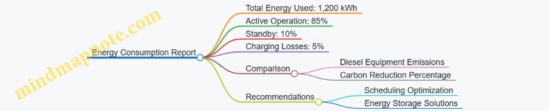
Example: Material Waste Reduction
In a robotic bricklaying project, waste was measured by counting unused or broken bricks at the end of each day. Automated placement reduced breakage by 30% compared to manual work. The report included daily waste counts, reasons for waste (e.g., misplacement, breakage), and a comparison to historical manual data.
Recommendations focused on further refining robot grip control and material handling to cut waste further.
Mind Map: Material Waste Reporting Example

Tips for Effective Reporting
- Use automated data collection wherever possible to reduce errors.
- Present data visually with charts and graphs for clarity.
- Include context by comparing robotic metrics to traditional methods.
- Keep reports concise but detailed enough to guide decisions.
- Update reports regularly to track progress over time.
By focusing on clear metrics and structured reporting, construction teams can objectively evaluate how autonomous robots contribute to sustainability goals and identify areas for improvement.