Cisco CCNP Enterprise Core Exam Prep
1. Exam Scope and Core Troubleshooting Mindset
1.1 Map Exam Objectives to Practical Lab Tasks
Mapping exam objectives to lab tasks is less about memorizing command lists and more about building a repeatable path from “what the question asks” to “what you should verify.” A good mapping turns vague goals like “troubleshoot routing” into concrete actions: reproduce, observe, isolate, correct, and confirm.
Objective Decomposition into Lab Outcomes
Start by rewriting each objective as a lab outcome statement. For example, instead of “OSPF adjacency issues,” use “Given two routers with mismatched OSPF parameters, identify why adjacency never forms and fix it.” This forces you to include both diagnosis and remediation.
Then split each outcome into four lab phases:
- Reproduce the failure state using a controlled change.
- Observe with the smallest set of show commands that narrows the problem.
- Isolate by checking the specific prerequisite the objective depends on.
- Confirm with verification that the system behaves as expected.
A practical rule: if you cannot name the prerequisite you’re checking, you’re not isolating—you’re guessing.
Mind Map: From Objective to Lab Execution
Build a Task Template You Can Reuse
Use the same lab template for every objective. This reduces cognitive load during exam-style troubleshooting.
Example Task Template
- Goal: Fix the issue so the required state is achieved.
- Controlled Change: Introduce one fault (wrong area, missing interface, incorrect ACL direction, etc.).
- Primary Symptom: What the show output or behavior reveals.
- First Verification: The command that confirms whether the prerequisite is met.
- Isolation Checks: Two to four targeted checks.
- Fix: The minimum configuration change.
- Final Verification: State and traffic checks that prove correctness.
Example: OSPF Adjacency Never Forms
- Controlled Change: Set Router A’s interface to area 0, but Router B’s same link to area 1.
- Primary Symptom: Neighbor state remains stuck (or never reaches Full).
- First Verification: Confirm interface is in the expected OSPF area on both sides.
- Isolation Checks:
- Confirm both interfaces are enabled for OSPF.
- Confirm matching area IDs.
- Confirm L3 reachability between the neighbors.
- Fix: Align the area configuration on both routers.
- Final Verification: Confirm neighbor state reaches Full and routes appear in the expected table.
The key is that you’re not just “running show ip ospf neighbor.” You’re using it to validate the specific prerequisite implied by the objective.
Prioritize Prerequisites with a Consistent Order
Most enterprise troubleshooting failures collapse into a few prerequisite layers. Use this order to avoid wandering:
- Layer Two reachability when relevant (VLANs, trunks, port state).
- Layer Three reachability (IP addressing, masks, default gateways, reachability).
- Protocol parameters (areas, timers, authentication, ASNs, route distinguishers).
- Policy and filtering (ACLs, route maps, prefix lists, redistribution rules).
If you skip a layer, you may “fix” the wrong thing. For instance, an ACL can make an OSPF adjacency look like a protocol mismatch.
Turn Objective Language into Expected Output Patterns
Exam questions often hinge on recognizing what “good” looks like. For each objective, define two expected patterns:
- State pattern: the protocol state you should see (e.g., adjacency Full, BGP Established).
- Data pattern: the resulting data plane effect (routes present, counters increment, traffic permitted).
Example: AAA Authentication Failure
- State pattern: AAA method list is applied and authentication attempts are logged.
- Data pattern: successful login produces expected privilege level; failed attempts show consistent error counters.
When you can name the state and data patterns, you can verify quickly without over-reading output.
Practical Lab Execution Rules
- Change one variable at a time. If two things change, you lose isolation.
- Save outputs before and after. Your future self will thank you.
- Use a short command set. Start broad enough to confirm the symptom, then narrow.
- Write the “why” in one sentence. If you can’t, the mapping wasn’t specific enough.
A mapping that works is one you can execute under time pressure: objective → outcome → prerequisite checks → minimal fix → confirmation.
1.2 Build a Reproducible Troubleshooting Workflow
A reproducible troubleshooting workflow turns “I think it’s probably X” into “I can prove it in a repeatable sequence.” The goal is not to be fast at guessing; it’s to be consistent at narrowing the problem until the fix is obvious.
Workflow Principles That Make Results Repeatable
Start with a stable loop: observe, hypothesize, test, conclude, and document. Each step should produce an artifact you can reuse: a timestamped observation, a command output snippet, a hypothesis statement, and a decision.
- Define the symptom precisely. Note the exact failure mode: packet loss, routing blackhole, authentication denial, or intermittent flaps. “Users can’t reach the server” is too vague; “HTTP to 10.10.20.5 fails from VLAN 30 clients but works from VLAN 10” is testable.
- Capture the baseline. Record what “good” looks like: working paths, expected routes, known-good VLANs, and normal CPU/memory levels. If you don’t know the baseline, you can’t tell whether your change helped.
- Use the smallest possible test. Prefer targeted verification commands over broad “show everything.” If you’re checking routing, verify routing first; if you’re checking L2, verify MAC learning and VLAN membership first.
- Make hypotheses falsifiable. A hypothesis should predict what you will see if it’s true. Example: “OSPF adjacency is down because hello/dead timers mismatch” predicts you’ll see neighbor state stuck at Init or ExStart.
- Stop when the evidence is sufficient. Reproducibility includes knowing when to stop. If your tests already prove the root cause, don’t keep collecting data “just in case.”
Mind Map: Troubleshooting Workflow
A Systematic Sequence You Can Reuse
Use a consistent order that matches how packets actually move.
Step 1: Confirm the failure boundary. From the client, test reachability to the destination IP and then test name resolution if relevant. If DNS fails but IP works, you’re not dealing with routing.
Step 2: Verify L2 reachability to the gateway. Check VLAN membership and trunk status on the access and distribution switches. A common “it’s routing” mistake is actually a VLAN mismatch: clients ARP for the gateway, but the gateway never receives the ARP because the VLAN isn’t carried.
Step 3: Verify gateway and L3 path. Confirm the default gateway is correct on the client side, then verify the gateway interface is up/up and the IP is present. Next, check that the routing table contains the destination prefix and that the route is installed (not just learned).
Step 4: Verify control-plane health. If the route is missing or stale, inspect the routing protocol adjacency and convergence state. For OSPF, confirm neighbor state and area consistency; for BGP, confirm session establishment and route-policy outcomes.
Step 5: Verify policy and data-plane enforcement. If the route exists but traffic still fails, check ACL counters, NAT translations, and VRF placement. A route can be correct and still be blocked by an ACL placed on the wrong interface or direction.
Example: Routing Blackhole That Looks Like “No Connectivity”
Symptom: VLAN 30 users cannot reach 10.10.20.5 over TCP 443. VLAN 10 users can.
Hypothesis 1: VLAN 30 is not reaching the gateway.
- Test: On the VLAN 30 access switch, verify the port VLAN assignment and trunk allowed VLAN list toward the gateway.
- Evidence: VLAN 30 is missing from the trunk allowed list.
- Conclusion: L2 boundary is broken; routing tests would be misleading.
Fix: Add VLAN 30 to the trunk allowed list and confirm the port is forwarding.
Validation: Re-test TCP 443 from a VLAN 30 client. Then confirm ARP entries appear on the gateway and that the routing table already had the correct route.
Example: Route Exists but Traffic Still Fails
Symptom: Pings to 10.10.20.5 fail, but traceroute shows the first hop is correct.
Hypothesis 2: ACL or VRF mismatch blocks ICMP or the specific protocol.
- Test: Check ACL counters on the interface where traffic enters the routing boundary. Also confirm the VRF context for both source and destination.
- Evidence: ACL counters increment on the ingress interface; deny rule matches the source subnet.
- Conclusion: Data-plane policy is the root cause.
Fix: Adjust ACL rule order or match criteria, then re-test.
Documentation Template for Reproducibility
Write down the minimum set of facts that another engineer could follow without guessing.
- Symptom statement and scope
- Commands run in order
- Key outputs (neighbor state, route presence, ACL counters)
- Hypotheses and which test disproved them
- Final root cause and exact change made
- Validation results
A workflow like this keeps troubleshooting from becoming a scavenger hunt. You still investigate, but every step leaves a trail that makes the next run faster and more accurate.
1.3 Interpret Show Commands and Output Patterns
When you run a show command in an exam-style lab, you are not collecting trivia. You are matching output patterns to a specific hypothesis: “Is the control plane behaving correctly?” or “Is the data plane forwarding as expected?” The trick is to read outputs in a consistent order so you don’t miss the one line that explains everything.
A Systematic Reading Order
Start with the smallest, most diagnostic objects, then expand.
- State and role: Identify whether the device is in the expected mode (routing enabled, correct VRF, correct interface role).
- Adjacencies and sessions: Confirm neighbors, peers, and protocol relationships are established.
- Control plane decisions: Check how routes are selected, installed, and summarized.
- Data plane behavior: Validate forwarding entries, counters, and traffic hits.
- Errors and counters: Look for drops, resets, authentication failures, and mismatched MTU.
A good habit is to circle the “why” fields: timers, reasons, flags, and selection criteria. Those fields usually appear once per output and do the heavy lifting.
Output Patterns You Should Recognize
Pattern 1: “Up/Down” With a Reason
Interface outputs often show up/down plus a reason such as admin down, line protocol down, or no carrier. If the line protocol is down, routing protocols won’t form adjacencies even if the interface is administratively up.
Example reasoning: If show ip interface brief says the interface is up but show interfaces shows line protocol down, you focus on physical or encapsulation mismatch rather than routing.
Pattern 2: Adjacency Tables with Timers
Routing and switching protocols typically show neighbor state plus hold times or uptime. A neighbor in Init or ExStart means negotiation isn’t complete; a neighbor in Full means the protocol has agreed on parameters.
Example reasoning: If OSPF neighbors are stuck with low uptime and repeated resets, you check MTU, area mismatch, authentication, and interface type.
Pattern 3: Route Selection Fields
Route outputs often include selection markers like best/installed, metric, preference, next hop, and flags. The exam expects you to connect those fields to the protocol you configured.
Example reasoning: If BGP shows multiple paths but only one is “best,” you verify the attributes that drive selection (local preference, AS path length, origin type, MED, and tie-breakers).
Pattern 4: Counters That Tell You Where Packets Went
Counters are not just numbers; they indicate whether traffic reached the device and whether it was forwarded or dropped.
Example reasoning: If interface input counters increase but output counters do not, you suspect ACL drops, policy drops, or routing/next-hop resolution issues.
Mind Map: Show Command Interpretation
Concrete Examples with “What to Look For”
Example: Interface and Routing Protocol Alignment
Run show ip interface brief first to confirm the interface is expected to be reachable. Then check show interfaces <int> for line protocol and encapsulation. Finally, verify protocol adjacency with the relevant show command.
What to look for:
line protocol is down→ physical/encapsulation/auth issue.- Interface up but no adjacencies → routing area, hello parameters, or authentication mismatch.
Example: Route Installation vs Route Presence
Some outputs show routes learned but not installed. If you only check the learned table, you might miss the reason the route is not in the forwarding table.
What to look for:
- “best” vs “not best” paths
- installed/forwarding markers
- next-hop reachability
Example: Counters with Directionality
Compare input and output counters on the same interface during a test ping or traceroute.
What to look for:
- Input increases, output stays flat → drop or policy block.
- Both increase but traffic fails end-to-end → next-hop or downstream issue.
Micro-Checklist for Exam Speed
- Identify the scope: global vs VRF.
- Identify the role: active/standby, best/backup, master/neighbor.
- Identify the reason: flags, timers, and drop causes.
- Tie it back to one hypothesis: “adjacency,” “selection,” or “forwarding.”
If you keep that order, the output stops feeling like a wall of text and starts behaving like a set of clues. The exam is basically asking you to read like a detective, not like a librarian.
1.4 Validate Configuration With Targeted Verification Steps
Validation is where “it looks right” becomes “it behaves right.” The goal is not to run every command you know, but to confirm the specific outcomes your configuration is supposed to produce. A good verification sequence starts with the control plane, moves to the data plane, and ends with the user-visible behavior.
Verification Principles That Prevent False Confidence
First, verify intent at the configuration level: confirm the exact objects you created (interfaces, VLANs, policies, neighbors, VRFs) exist and match what you think you deployed. Second, verify operational state: confirm the device is actually using those objects. Third, verify traffic behavior: confirm packets take the expected path and are permitted or translated as designed.
A practical way to avoid false confidence is to pair each configuration change with a single “must be true” statement. For example, if you changed an OSPF network statement, the must-be-true outcome is that the intended interfaces are in the correct OSPF area and form adjacencies.
Step 1: Confirm the Configuration Objects Exist
Start with “show me what’s configured,” not “show me what’s happening.”
- Interfaces: confirm the interface is up, has the right L3/L2 mode, and carries the expected addressing.
- Routing processes: confirm the process exists, the router ID is correct, and the relevant networks or areas are present.
- Policies: confirm prefix lists, route maps, and match/set clauses are present and attached.
- Security and management: confirm ACLs, AAA methods, and management access settings are applied to the correct interfaces or lines.
Example: After changing an interface into an OSPF area, verify the interface is actually part of that area by checking the interface’s OSPF configuration and then confirming the area assignment in operational output.
Step 2: Confirm the Control Plane Is Converged
Once objects exist, confirm the control plane is stable.
- Adjacencies and neighbors: confirm the neighbor state is established (or the expected equivalent), and check for mismatches such as area ID, authentication, timers, or MTU.
- Route tables: confirm the routes you expect appear in the correct table (global vs VRF), and confirm their next hop and administrative distance.
- Policy effects: confirm route counters or match statistics show the intended prefixes are being processed.
Example: If a route map is supposed to block a prefix, you should see the prefix match counters increment while the resulting route is absent from the advertised or installed set.
Step 3: Confirm the Data Plane for the Specific Flows
Control plane correctness does not guarantee forwarding correctness. Validate the data plane using targeted traffic tests.
- Path validation: confirm the forwarding decision using the route lookup result for a test destination.
- ARP and neighbor resolution: confirm L2-to-L3 adjacency is healthy for the next hop.
- ACL and segmentation: confirm permitted/denied behavior using counters and a controlled test host.
Example: If an ACL is applied inbound on an SVI, test a single source/destination pair that should be allowed and another that should be denied. Then confirm ACL hit counters move in the expected direction.
Step 4: Validate Edge Cases That Commonly Break
Edge cases are where exam-style scenarios hide. Validate the details that change behavior without changing the headline configuration.
- MTU and fragmentation: confirm consistent MTU across links where routing protocols rely on it.
- Asymmetric routing: confirm return path expectations, especially when policy-based routing or multiple exit points exist.
- Default routes and summarization: confirm the presence and scope of defaults and summaries.
- Failover behavior: confirm that the expected standby or alternate path activates and that traffic resumes without lingering blackholes.
Mind Map: Targeted Verification Flow
Example: Verification Checklist for a Routing Change
Assume you added a new OSPF network statement to include a subnet.
- Object check: confirm the interface is in the expected VRF and the subnet is covered by the new statement.
- Control plane check: confirm the interface is listed under the correct OSPF area and adjacencies are established.
- Route check: confirm the new prefix appears in the routing table with the expected next hop.
- Data plane check: send a ping or traceroute to a host in the new subnet and confirm the forwarding path uses the expected next hop.
- Edge check: verify MTU and authentication match on the adjacency path.
Example: Verification Checklist for an ACL Change
Assume you added an extended ACL to restrict access to a server subnet.
- Object check: confirm the ACL name and sequence numbers are correct and the ACL is applied in the correct direction.
- Control plane check: confirm no related management or routing access is unintentionally blocked.
- Data plane check: test one allowed flow and one denied flow.
- Counter check: confirm ACL counters increment for the denied flow and increment for the allowed flow only where expected.
- Edge check: verify return traffic is permitted, not just the initial request.
A Simple Verification Rhythm That Stays Consistent
Use a repeatable rhythm: confirm the configured object, confirm the operational state, confirm the forwarding decision, and confirm the user-visible result. When something fails, the last confirmed layer tells you where to look next—configuration, control plane, or data plane—without guessing.
1.5 Document Findings and Create Repeatable Runbooks
A good runbook turns “what happened” into “what to do next,” and it does so in a way that another engineer can follow under time pressure. The goal is not to write a novel; it’s to capture decisions, evidence, and the exact verification steps that prove the fix.
What to Capture During Troubleshooting
Start with a consistent template so you never rely on memory. Use these fields every time:
- Problem statement: Symptom, scope, and impact. Example: “Users in VLAN 20 cannot reach the default gateway; VLAN 10 works.”
- Timeline: When it started, what changed, and what you tried in order.
- Hypotheses: The top 2–4 likely causes, each tied to observed evidence.
- Evidence: Command outputs or key counters, with the exact command used.
- Decision points: Why you moved forward or stopped. Example: “OSPF neighbor state stuck in ExStart; MTU mismatch suspected because interface MTU differs.”
- Fix actions: The precise configuration changes, including interface/VLAN/VRF context.
- Verification: The commands that confirm the problem is gone and stays gone.
- Rollback plan: What to revert if verification fails.
A practical rule: if you can’t point to the evidence that supports a decision, the runbook should say “not proven.” That honesty saves time later.
Runbook Structure That Scales
A runbook should read like a checklist with guardrails. Use this order:
- Preconditions: Access method, device role, and what “normal” looks like.
- Symptoms and scope: What to confirm first.
- Step-by-step procedure: Each step ends with a verification check.
- Common failure modes: Short branches for the most frequent wrong turns.
- Rollback and escalation: What to revert and when to stop.
Keep steps atomic. If a step includes multiple changes, verification becomes ambiguous.
Mind Map: Runbook Content Flow
Example Runbook Entry for an OSPF Adjacency Issue
Problem statement: OSPF neighbors between R1 and R2 never reach Full; both sides show adjacency stuck at ExStart.
Preconditions: Confirm you have console/SSH access, and you can run show commands without paging.
Procedure:
- Confirm interface and area
- Run:
show ip ospf interface brief - Verify: Both sides list the same area ID and the interface is in the expected VRF.
- Run:
- Check neighbor state and timers
- Run:
show ip ospf neighbor - Verify: State is consistently ExStart on both routers.
- Run:
- Validate MTU and L3 reachability
- Run:
show interface <iface> | include MTU|line protocol - Verify: MTU matches on both ends and the interface is up/up.
- Run:
- Confirm authentication alignment
- Run:
show ip ospf interface <iface> - Verify: Authentication type and keying method match.
- Run:
- Apply the smallest corrective change
- Example fix: Align MTU or authentication settings.
- Verification
- Run:
show ip ospf neighbor - Verify: Neighbor reaches Full and stays stable for several seconds.
- Run:
Rollback: If the change was authentication-related, revert to the previous authentication configuration before the next verification cycle.
Notice what’s missing: no guesswork. Each step ends with a check that narrows the cause.
Mind Map: Evidence to Verification Mapping
Practical Writing Rules That Make Runbooks Usable
- Use exact commands: “show ip ospf neighbor” beats “check OSPF neighbors.”
- Record outputs selectively: Include the key lines that justify the decision.
- Avoid vague success criteria: Say what “fixed” means, such as “neighbor is Full on both routers.”
- Include context: VRF, interface name, VLAN ID, and area ID prevent misapplication.
A runbook is a tool for future you and someone else. If it can’t be followed without asking questions, it’s not finished yet.
2. Enterprise Routing Foundations with OSPF and EIGRP
2.1 Configure And Verify OSPFv2 For IPv4
OSPFv2 for IPv4 is a link-state routing protocol that builds a map of the network from router advertisements. Your job in the exam and in real networks is to make sure three things line up: neighbors form, the link-state database is consistent, and the resulting routes match the design.
Core Concepts That Drive Verification
OSPF routers exchange Hello packets to discover neighbors. The Hello parameters must match on both sides, including area ID, authentication method, and timers. Once neighbors are established, routers flood link-state advertisements (LSAs) and build a shared view of the topology within each area.
Verification should therefore follow a simple order: adjacency first, then database consistency, then route installation.
Mind Map: OSPFv2 Verification Flow
Step 1: Configure OSPFv2 With Predictable Parameters
Start by choosing the process ID and router ID. The process ID is local to the router; the router ID is what neighbors use to identify you. If you don’t set router ID explicitly, OSPF may pick one based on interface addresses, which can change after reboots.
Next, define the area. For most enterprise designs, you’ll see a backbone area (area 0) and one or more non-backbone areas. A router can only exchange routes between non-backbone areas through area 0, so placing links into the correct area matters.
Finally, enable OSPF on the correct interfaces. The network statement ties an interface to an OSPF area and network type. For point-to-point links, use point-to-point or point-to-multipoint; for broadcast networks, use broadcast. Mismatched network types can prevent full adjacency even when IP reachability is fine.
Step 2: Verify Neighbor Adjacencies Like You Mean It
Use these checks in sequence.
-
Confirm OSPF is running and the router ID is what you expect.
-
Check neighbor state. You want to see full adjacency for the links that should carry routing information.
-
If neighbors are stuck, inspect why. The most common causes are mismatched area IDs, mismatched authentication, or timer differences.
Example verification commands and what to look for:
show ip ospf neighbor
show ip ospf interface brief
show ip protocols
show ip ospf
Interpretation tips:
show ip ospf neighborshould list neighbors with stateFULL/DRorFULL/BDRon broadcast networks.show ip ospf interface briefshould show the interface in the correct area and indicate that it is sending and receiving Hellos.
Step 3: Verify Link-State Database Consistency
Adjacency alone doesn’t guarantee correct routing. OSPF must also converge its LSDB so that SPF calculations produce the expected routes.
Check for excessive LSA retransmissions and confirm that the LSDB is populated for the area(s) you designed.
show ip ospf database
show ip ospf statistics
show ip ospf retransmission-list
If the database looks empty for an area where you expect routes, revisit interface membership and area assignment. If retransmissions are high, suspect MTU issues, packet loss, or authentication mismatches.
Step 4: Verify Route Installation and Cost Behavior
Once LSDB is consistent, OSPF installs routes into the routing table. Verify that:
- Routes appear in the expected routing table entries.
- Next-hop values match the topology.
- Costs align with your design assumptions.
show ip route ospf
show ip route
show ip ospf route
show ip ospf border-routers
Cost sanity check: OSPF cost is derived from interface bandwidth (or explicit cost if configured). If two paths exist, the lower total cost should win. When routes look “wrong,” it’s often because one interface has an unexpected cost or because a link was placed into the wrong area.
Example: A Clean IPv4 OSPFv2 Setup and Verification
Assume Router A and Router B connect over a point-to-point link, both in area 0.
- Ensure both sides have matching area 0.
- Ensure both sides are using the same authentication method (or none).
- Ensure Hello/Dead timers match.
Verification checklist:
show ip ospf neighborshows FULL adjacency.show ip ospf interface briefshows both interfaces in area 0.show ip route ospfincludes the expected remote networks.
Mind Map: What Each Verification Output Tells You
Common Exam Traps and How Verification Exposes Them
If you see neighbors in 2-WAY but never FULL, focus on broadcast network roles, network type, and authentication/timer mismatches. If you have FULL but no OSPF routes, check area assignment and whether the interfaces are actually participating in OSPF. If routes exist but are not the ones you expect, compare interface costs and confirm that the winning path is the one with the lowest total cost.
A good habit is to treat verification as a chain: adjacency enables LSDB exchange, LSDB enables SPF, and SPF enables route installation. When you break the chain at the first missing link, troubleshooting becomes fast instead of guessy.
2.2 Configure and Verify OSPFv3 For IPv6
OSPFv3 runs on IPv6 and uses link-local addresses for neighbor discovery, while routing information is carried in IPv6 unicast. The key mental model is separation: neighbor formation depends on interfaces and link-local reachability, while route advertisement depends on areas and interface participation.
Foundational Concepts That Affect Verification
OSPFv3 uses these building blocks:
- OSPF process: the container for OSPFv3 settings.
- OSPFv3 router-id: a stable 32-bit identifier used for DR/BDR election and internal logic.
- Areas: route boundaries; all routers in an area share the same LSDB scope.
- Interfaces: each interface must be explicitly enabled for OSPFv3, and each interface has an area assignment.
- Link-local addressing: neighbors form using link-local reachability, so IPv6 link-local must be present and not blocked.
A practical verification habit: always confirm neighbor adjacency first, then confirm LSDB and route installation. If you skip adjacency checks, you can waste time staring at routes that will never appear.
Configuration Approach with Clear Steps
- Enable IPv6 on interfaces and ensure link-local addresses exist.
- Create the OSPFv3 process and set a router-id.
- Enable OSPFv3 per interface and assign the correct area.
- Match area and interface parameters across neighbors.
- Verify adjacency and route learning.
Example Configuration
ipv6 unicast-routing

interface GigabitEthernet0/0
 ipv6 address 2001:db8:10:1::1/64
 ipv6 ospf 1 area 0

interface GigabitEthernet0/1
 ipv6 address 2001:db8:10:2::1/64
 ipv6 ospf 1 area 0

router ospfv3 1
 router-id 1.1.1.1
If you need a non-backbone area, the only change is the area value on the relevant interfaces. Keep the router-id consistent with your troubleshooting notes so you can quickly identify which device you are reading in outputs.
Verification Workflow That Prevents Guesswork
Use a three-layer checklist: interfaces, neighbors, then routes.
Interface and Link-Local Checks
- Confirm IPv6 is enabled and interfaces have IPv6 addresses.
- Confirm link-local addresses exist and are reachable on the segment.
- Ensure the interface is actually participating in OSPFv3.
Commands to use:
show ipv6 interface briefshow ipv6 ospf interface
A common failure mode is an interface that has IPv6 configured but is missing ipv6 ospf 1 area X, which makes it look “mostly right” while still producing no adjacencies.
Neighbor Adjacency Checks
Adjacency state tells you whether OSPFv3 is progressing.
Commands to use:
show ospfv3 neighborshow ospfv3 interface
Look for neighbors in states like Full (or at least progressing beyond initial states). If neighbors never appear, focus on link-local reachability and matching interface area configuration.
LSDB and Route Installation Checks
Once neighbors are up, verify that LSAs are being exchanged and routes are installed.
Commands to use:
show ospfv3 routeshow ipv6 route ospfshow ospfv3 database(use carefully; it can be large)
If you see LSDB activity but no routes, check whether the area and interface settings match what the other side expects, and confirm you are looking at the correct VRF if your design uses VRFs.
Mind Map: OSPFv3 Verification
OSPFv3 Configure and Verify Mind Map
Example Troubleshooting Scenarios
Scenario 1: Neighbors never show up.
Start with show ipv6 ospf interface to confirm OSPFv3 is enabled on the interface. Then check show ospfv3 neighbor. If the interface is enabled but neighbors are absent, verify that link-local addresses can reach each other on that segment and that both sides use the same area.
Scenario 2: Neighbors appear but routes are missing.
Run show ospfv3 route and show ipv6 route ospf. If OSPF routes are absent, confirm that the interfaces on both routers are assigned to the same area and that you are not mixing VRFs. Also ensure the router-id is set; a missing or inconsistent router-id can make outputs confusing even when the protocol is otherwise healthy.
Verification Summary You Can Reuse
A reliable order is: interface participation → neighbor adjacency → route installation. When you follow that sequence, each command narrows the problem space instead of expanding it, and you spend less time interpreting output and more time fixing the actual mismatch.
2.3 Control Route Selection with Areas and Summarization
OSPF and EIGRP both need a way to decide what to learn, what to advertise, and what to keep quiet. In OSPF, that control is largely achieved with areas and summarization. The goal is simple: reduce routing churn and keep the routing database focused on what each router truly needs.
Core Idea of OSPF Areas
An OSPF area is a logical boundary that limits how much link-state information floods. Routers inside the same area exchange detailed topology data, while inter-area routing is handled through Area Border Routers (ABRs). ABRs maintain separate link-state databases per area and translate between them.
A practical way to remember it: if every router flooded everything everywhere, your network would behave like a group chat with no mute button. Areas are the mute button.
How Route Selection Changes with Area Design
Route selection in OSPF is not only about the shortest path cost. It also depends on what information is available in the local routing table.
- Intra-area routes are computed from the local area’s topology.
- Inter-area routes are learned as summary routes originated by ABRs.
- Default routes can be injected by ABRs to avoid carrying full detail when it’s unnecessary.
This means your area design directly affects which paths are even candidates for selection.
Summarization Fundamentals
Summarization reduces the number of prefixes carried between areas. ABRs can advertise a summarized route for a range of networks instead of many individual subnets.
Key constraints:
- Summarization must match the actual addressing plan. If you summarize incorrectly, you can blackhole traffic.
- More specific routes are preferred when present. If a more specific prefix exists in the receiving area, it will override the summary.
- Summaries should be placed where they reduce churn without hiding critical topology changes.
Mind Map: Areas and Summarization
Example: Area Boundary and Summary Behavior
Assume Area 0 is the backbone and Area 10 is a campus. Area 10 contains multiple subnets: 10.10.1.0/24, 10.10.2.0/24, and 10.10.3.0/24. Without summarization, ABR-to-Area-0 traffic carries each prefix separately. With summarization, ABR can advertise 10.10.0.0/16 into Area 0.
What changes for route selection?
- Routers in Area 0 now see a single inter-area route candidate (10.10.0.0/16) instead of three.
- If Area 0 also contains a specific route like 10.10.2.0/24 from another source, that more specific route will win for that destination.
- If a host in 10.10.4.0/24 sends traffic, it will match the summary and be forwarded toward the ABR, but the ABR will not have a real more-specific route. That’s why summaries must reflect real reachable networks.
Example: Default Route to Reduce Unnecessary Detail
Sometimes Area 10 is a leaf that only needs to be reached, not fully understood. In that case, ABR can advertise a default route into Area 10. Routers in Area 10 then send unknown destinations to the ABR, avoiding the need to store many inter-area prefixes.
This is especially useful when most traffic from Area 10 goes to a small set of destinations reachable via the backbone.
Verification Checklist for Exam-Style Scenarios
When you’re asked to “control route selection,” verify three things in order:
- Area membership and ABR role
- Confirm which routers are ABRs and which areas they connect.
- Summary advertisement
- Check that the ABR is advertising the intended summarized prefix into the target area.
- Routing table outcome
- Confirm that receiving routers install the summary (and not an unexpected more specific route).
If the routing table doesn’t match expectations, the most common causes are wrong area assignment, missing ABR connectivity, or a summary that doesn’t align with actual reachable networks.
Practical Configuration Pattern
In OSPF, summarization is typically configured on the ABR at the boundary between areas. The exact syntax varies by platform and OSPF version, but the logic stays consistent: define the summary range, apply it to the outgoing area, and verify the resulting inter-area route.
Goal
- ABR advertises summarized inter-area prefix into Area 0 or Area 10

Inputs
- Correct area IDs
- Correct summary range that matches real subnets

Validation
- Receiving router shows summary in routing table
- No unexpected more-specific routes override it
When you design areas and summaries together, you’re not just “organizing” OSPF. You’re shaping the set of routes that routers are allowed to consider, which is the real lever behind controlled route selection.
2.4 Configure and Verify EIGRP for IPv4 And IPv6
EIGRP is a distance-vector routing protocol that behaves like it has a plan: it uses neighbor discovery, reliable updates, and a topology table to decide whether a route is feasible. For the exam, the key is not memorizing every knob—it’s knowing which verification output proves the protocol is healthy.
Mind Map: EIGRP IPv4 And IPv6 Verification Flow
Foundational Concepts That Affect Configuration
EIGRP forms adjacencies when both sides agree on the autonomous system number and the parameters that influence metric calculation. For IPv4, the network statement uses a wildcard mask; for IPv6, you must enter the address-family context and then define the IPv6 network prefix. If you get the network statement wrong, EIGRP will still start, but it will never advertise on the intended interfaces.
EIGRP also has a concept of feasibility: a route is considered feasible if the reported distance from a neighbor is less than the current best distance. That’s why the topology table matters—exam questions often hinge on whether a feasible successor exists.
Configure EIGRP for IPv4 With Practical Checks
Start with a simple two-router lab: R1 and R2 connected by a /30. Use the same AS number on both sides and ensure the interface is not passive.
R1# configure terminal
R1(config)# router eigrp 10
R1(config-router)# network 10.0.0.0 0.0.0.3
R1(config-router)# no passive-interface g0/0
R1(config-router)# end
On R2, mirror the AS and network statement.
Verification should be immediate and specific:
show ip eigrp neighborsshould list the neighbor with uptime and interface.show ip eigrp topologyshould show routes with successor and feasible successor markers.show ip route eigrpshould confirm the learned prefixes are installed.
If neighbors do not appear, check for AS mismatch, K-value mismatch, or an interface that is effectively excluded by the network statement.
Configure EIGRP for IPv6 With Address-Family Context
IPv6 EIGRP requires entering the address-family and then defining the IPv6 network. A common mistake is configuring IPv4-style network statements without the address-family context.
R1# configure terminal
R1(config)# router eigrp 10
R1(config-router)# address-family ipv6 unicast
R1(config-router-af)# network 2001:db8:10::/64
R1(config-router-af)# no passive-interface g0/0
R1(config-router-af)# end
Repeat on R2 with the same AS and matching prefix for the connected link.
Verification mirrors IPv4 but uses IPv6 commands:
show ipv6 eigrp neighborsconfirms adjacency.show ipv6 eigrp topologyconfirms successor and feasible successor.show ipv6 route eigrpconfirms installation into the IPv6 routing table.
If IPv6 neighbors form but routes do not install, focus on whether the prefix you expect is actually being advertised and whether the topology table shows the route as feasible.
Example: Interpreting Feasible Successor Output
Suppose R1 learns a route to 192.168.50.0/24 via R2. If R1 loses the current successor path, EIGRP can switch to a feasible successor without waiting for recomputation.
In show ip eigrp topology, look for:
- A successor entry for the route.
- A feasible successor entry that is marked as feasible.
If you only see a successor and no feasible successor, convergence may require additional steps, and exam questions may expect you to describe that behavior.
Common Verification-Driven Troubleshooting
- Neighbors missing: confirm AS number, confirm the interface is included by the network statement, and confirm the interface is not passive.
- Neighbors present but no routes: confirm the advertised prefix exists on the neighbor, then check topology for successor/feasible successor presence.
- Routes present but unstable: check whether metric components are consistent enough to produce feasible paths; mismatched K-values can cause unexpected selection.
Integrated Best Practices for Exam-Ready Confidence
Use one consistent pattern: configure EIGRP, verify neighbors, verify topology, then verify route installation. For IPv4 and IPv6, keep the same mental checklist and only swap the command set. This reduces the chance of “it’s running but it’s not doing anything,” which is the most common exam trap.
2.5 Troubleshoot Adjacencies and Route Convergence
Adjacencies form the “who’s connected to whom” layer, while convergence is the “what routes are now agreed upon” layer. In OSPF and EIGRP, a broken adjacency usually prevents route exchange; in BGP, session state controls which routes are even eligible to be installed. A good troubleshooting flow keeps you from chasing symptoms.
Mind Map: Adjacency to Convergence Workflow
Step 1: Verify Reachability and Interface Preconditions
Start with the boring stuff because routing protocols are picky. Confirm interfaces are up and configured as expected, then verify that the neighbor’s IP is reachable from the local router.
For OSPF, ensure the interface is in the correct area and that the MTU matches on both sides; mismatched MTUs can stop adjacency even when IP reachability works. For EIGRP, confirm the interface is not passive and that the AS and interface settings match. For BGP, confirm TCP connectivity to the neighbor IP and port 179; if TCP fails, everything else is irrelevant.
Example: If OSPF neighbors never form, check that both sides use the same area ID and the same authentication method. A common mistake is one side using plaintext authentication while the other expects keyed authentication.
Step 2: Verify Adjacency Formation State
OSPF adjacency troubleshooting is about matching parameters and ensuring the routers can exchange LSAs. Use a two-lane approach: first confirm neighbor discovery, then confirm full adjacency.
- If neighbors show as “2-Way,” the routers see each other but cannot progress to “Full.” This often points to area mismatch, authentication mismatch, or network type issues.
- If neighbors remain “Down,” focus on hello/dead timer mismatches, interface network type, or blocked multicast/neighbor reachability.
EIGRP adjacency depends on consistent K-values, AS number, and interface settings. If neighbors appear but routes never populate, check whether the interface is passive or whether summarization prevents the expected prefixes from being advertised.
BGP adjacency is session state. If the session is not established, focus on TCP reachability, correct neighbor configuration, and address-family activation. A session can be established while no routes appear if the AFI/SAFI is not enabled or route policies filter everything.
Step 3: Validate Route Exchange and Convergence Mechanics
Once adjacency is correct, convergence is about whether the control plane has learned and installed routes.
For OSPF, convergence includes LSDB synchronization. If you see “Full” adjacency but routes are missing, verify that the relevant networks are actually being originated into OSPF and that route types are not being filtered by area design. Also confirm that the next-hop is reachable in the routing table.
For EIGRP, convergence is tied to topology changes and successor selection. If routes are present in the topology table but not in the routing table, check feasibility conditions and whether the successor is valid. A frequent exam-style issue is a route being learned but not installed due to an unexpected metric or because the route is marked as not feasible.
For BGP, convergence means the best-path selection process has produced a usable route. Verify received prefixes, then verify why a candidate path is not selected: local preference, AS-path length, MED (where applicable), and route-policy outcomes. Also confirm that the next-hop is resolvable; BGP can learn a prefix but still not install it if the next-hop is unreachable.
Example: OSPF Adjacency Stalls at Two-Way
Scenario: Two routers are connected on a point-to-point link. You expect Full adjacency but only see “2-Way.”
- Confirm both interfaces are in the same area.
- Confirm authentication settings match.
- Confirm hello/dead timers match.
- Confirm network type and MTU match.
If authentication differs, the routers can still exchange some information, but LSDB synchronization fails, so the adjacency never reaches Full.
Example: BGP Established but No Routes Installed
Scenario: BGP session is “Established,” yet the routing table has no learned prefixes.
- Verify AFI/SAFI activation for the neighbor.
- Check inbound route policy effects on received routes.
- Confirm that the advertised prefixes exist and match the prefix-list conditions.
- Verify next-hop reachability.
If the inbound policy drops all prefixes, the session stays up because TCP and BGP keepalives work, but convergence of routing information never happens.
Practical Verification Checklist
Use a consistent order: adjacency state first, then exchange evidence, then installation evidence. When you change one parameter, re-check the same three layers so you can tell whether the fix affected discovery, synchronization, or installation.
A quick mental model helps: if adjacency fails, you’re stuck at “who”; if adjacency succeeds but routes don’t appear, you’re stuck at “what”; if routes appear but forwarding fails, you’re stuck at “where to send.”
3. Advanced Routing with BGP and Route Policy
3.1 Configure BGP Sessions With Correct Address Families
BGP neighbors can exchange multiple types of reachability information. The exam-friendly way to think about it is simple: you must make the session agree on what address families they will carry, and you must make the configuration match the platform’s expectations. If the families don’t line up, the session may still come up, but you’ll see no useful routes.
Foundational Concepts That Prevent “It’s Up, but Nothing Works”
Address family selection happens at two layers. First, the neighbor relationship must be established at the transport layer (TCP). Second, BGP must negotiate the address families for which it will send and receive NLRI (Network Layer Reachability Information).
On Cisco IOS XE, you typically enable families under the BGP address-family configuration. For IPv4 unicast, the family is ipv4 unicast. For IPv6 unicast, it is ipv6 unicast. If you only configure one side, the other side may still form a session but won’t exchange the missing family.
A practical mental checklist:
- Confirm TCP connectivity and session state.
- Confirm both sides are configured for the same address family.
- Confirm route-policy or prefix filtering isn’t silently discarding everything.
Configuration Approach with Clear Boundaries
Use a consistent pattern: define the neighbor, then explicitly configure the address family under the BGP process. Keep the family blocks symmetrical across peers.
Example: IPv4 Unicast Between Two Routers
router bgp 65001
 bgp log-neighbor-changes
 neighbor 192.0.2.2 remote-as 65002
 address-family ipv4 unicast
  neighbor 192.0.2.2 activate
 exit-address-family
This activates IPv4 unicast for that neighbor. Without activate, the neighbor won’t exchange IPv4 NLRI even if the session is established.
Example: Dual-Stack With IPv4 and IPv6 Unicast
router bgp 65001
 bgp log-neighbor-changes
 neighbor 2001:db8:1::2 remote-as 65002
 neighbor 192.0.2.2 remote-as 65002
 address-family ipv4 unicast
  neighbor 192.0.2.2 activate
 exit-address-family
 address-family ipv6 unicast
  neighbor 2001:db8:1::2 activate
 exit-address-family
Notice the separation: IPv4 and IPv6 families are activated independently. This prevents accidental “IPv6 neighbor activated for IPv4” mistakes that waste time during troubleshooting.
Mind Map: Address Family Alignment
Verification That Matches the Configuration
After applying the configuration, verify in the same order you configured.
- Confirm the session is established:
- Look for
Establishedinshow ip bgp summary(IPv4) andshow bgp ipv6 unicast summary(IPv6).
- Confirm the neighbor is active for the family:
- Use family-specific neighbor output to ensure the address family is actually negotiated.
- Confirm routes are being received:
- Check
show ip bgp neighbors <ip> received-routesfor IPv4. - Check
show bgp ipv6 unicast neighbors <ip> received-routesfor IPv6.
If the session is established but received-routes is empty, the problem is usually one of these: family activation mismatch, prefix filtering, or the peer not advertising anything for that family.
Integrated Example: Diagnosing a Family Mismatch Quickly
Assume Router A has ipv4 unicast activated toward Router B, but Router B only activates ipv6 unicast. The session may still show as established because TCP is fine. However, Router A will not receive IPv4 NLRI, and Router B will not receive IPv4 NLRI either.
A fast fix is to compare the address-family blocks on both sides and ensure both peers include:
address-family ipv4 unicastneighbor <peer-ip> activate
Then re-check received routes. If you see prefixes appear, you’ve confirmed the family negotiation was the blocker.
Best Practices That Keep the Exam and Real Networks Aligned
- Configure address-family activation explicitly for each neighbor.
- Keep IPv4 and IPv6 activation separate and readable.
- Verify per-family received routes, not just the overall session state.
- When troubleshooting, treat “Established” as a transport success, not a reachability success.
That’s the core idea: BGP can be up while the useful part is still missing. Correct address-family configuration makes sure the session carries the routes you actually care about.
3.2 Implement Route Policy with Prefix Lists and Route Maps
Route policy is how you decide which routes a router accepts, prefers, or advertises. In BGP, the decision points are explicit: you can filter routes using prefix lists, then apply more nuanced logic with route maps. Think of prefix lists as “bouncers with a clipboard” and route maps as “the script that decides what to do after the bouncer lets someone in.”
Foundational Concepts for Filtering and Matching
A prefix list matches routes by IP prefix and optional length constraints. For example, you might allow only 10.10.0.0/16 and its more specific subnets up to /24. This prevents accidental advertisement of overly broad or overly specific networks.
A route map applies ordered rules. Each rule has a sequence number and a match clause. If a route matches, the set clause changes attributes (like local preference) or permits/denies the route. If no rule matches, the default behavior is deny, which is why “explicit is kind” in exam scenarios.
Prefix List Design That Avoids Surprises
Start by writing down what you want to allow or block, then translate it into prefix list entries.
Example goal: allow only customer routes 203.0.113.0/24 through 203.0.113.0/25, but block everything else in 203.0.113.0/24.
ip prefix-list CUST-IN seq 5 permit 203.0.113.0/24 le 25
ip prefix-list CUST-IN seq 10 deny 0.0.0.0/0
The deny at the end is optional because an implicit deny exists, but including it makes intent unambiguous when you review configs under time pressure.
Route Map Logic with Ordered Rules
Now add a route map that uses the prefix list and sets attributes. Suppose you want to prefer routes from a primary upstream by raising local preference.
route-map UPSTREAM-PRIMARY permit 10
 match ip address prefix-list CUST-IN
 set local-preference 200

route-map UPSTREAM-SECONDARY permit 20
 match ip address prefix-list CUST-IN
 set local-preference 150
If a route does not match CUST-IN, it won’t be permitted by these rules. That means you should ensure the prefix list is correct before blaming BGP.
Applying Route Maps at the Correct BGP Hooks
In BGP, route maps are applied at specific points such as inbound filtering (routes received) or outbound advertisement (routes sent). A common mistake is applying the route map to the wrong direction.
Example: apply UPSTREAM-PRIMARY to routes received from neighbor 192.0.2.1.
router bgp 65000
 neighbor 192.0.2.1 remote-as 65001
 neighbor 192.0.2.1 route-map UPSTREAM-PRIMARY in
For outbound control, you’d use the same route map with out. The exam often tests whether you can reason about “in vs out” without memorizing.
Mind Map: Prefix Lists and Route Maps
Verification That Proves the Policy Works
After applying policy, verify in three layers: prefix match, route map hit counters, and BGP outcome.
-
Confirm prefix list behavior by checking which prefixes are permitted. In practice, you can test by looking at received routes and comparing them to the prefix list constraints.
-
Check route map counters to see whether rules are being hit. If counters stay at zero, the match condition is wrong or the route never reaches that policy.
-
Confirm the BGP best path selection. If local preference is set correctly, the preferred path should appear as the best route in the BGP table.
A practical habit: when troubleshooting, change one variable at a time. If you modify both prefix list and route map, you won’t know which change caused the result.
Example Walkthrough with Clear Outcomes
Assume two upstream neighbors both send the same customer prefixes. Your prefix list allows only 203.0.113.0/24 le 25. Your route maps permit those prefixes and set local preference to 200 for the primary and 150 for the secondary.
Result: BGP selects the primary neighbor’s route as best because local preference is higher. If you accidentally used le 24 instead of le 25, the /25 routes would be filtered out, and you’d see fewer prefixes in the BGP table. That’s the kind of mismatch the exam loves because it’s deterministic: the math of prefix lengths decides everything.
3.3 Use Attributes to Influence Path Selection
BGP chooses a best path using a deterministic sequence of rules. Attributes are the knobs that those rules read. Think of them as labeled facts attached to each route, not as “extra settings.” If two routes share the same prefix, BGP compares their attributes in order and picks the winner.
Foundational Attribute Types
Start with the attribute categories you’ll see in exam scenarios:
- Well-known mandatory: always present. If missing, the route is invalid.
- Well-known discretionary: commonly present and compared.
- Optional transitive: may be unknown to a router but must be passed along.
- Optional non-transitive: may be dropped if not understood.
In practice, you mostly care about the attributes that drive the decision process:
- Local Preference \( LOCAL_PREF \): used inside an AS. Higher wins.
- AS Path: shorter is preferred.
- Origin: IGP is preferred over EGP over incomplete.
- Multi-Exit Discriminator (MED): compared across neighbors in the same AS, typically lower is better.
- Next Hop: must be reachable; otherwise the route can’t be used.
- Weight: Cisco-specific, local to the router. Higher wins.
Decision Order with a Concrete Example
Assume AS 65010 has two eBGP neighbors advertising the same prefix 203.0.113.0/24.
- Neighbor A sends: LOCAL_PREF is not carried across eBGP; your router sets it via policy. AS_PATH is 65020 65030. ORIGIN is IGP.
- Neighbor B sends: AS_PATH is 65040. ORIGIN is incomplete.
If you do nothing, BGP will compare attributes in its standard order. AS Path length is a major early factor, so Neighbor B’s shorter AS Path often wins. If you want Neighbor A to win for business reasons, you raise LOCAL_PREF for routes learned from Neighbor A. That changes the outcome before AS Path is considered.
Mind Map: Attribute Flow and Best Path Logic
How to Influence Path Selection Systematically
-
Match the right routes first Use prefix lists to avoid accidental matches. For example, match only 203.0.113.0/24 and not the whole 203.0.113.0/23.
-
Set attributes at the correct boundary
- Use route-map applied to the neighbor to set LOCAL_PREF for routes learned from that neighbor.
- Use weight only when you want a decision local to one router.
-
Keep attribute intent consistent If you set LOCAL_PREF higher for Neighbor A, you should not later override it with another policy that matches the same routes. Conflicting policies are a common “why isn’t it working” cause.
-
Use MED carefully MED is compared when routes are from the same neighboring AS. If you compare MED across different ASes, behavior may not align with your expectations. A safe approach is to normalize MED comparison by ensuring you’re comparing routes in the intended context.
Example: LOCAL Preference to Prefer One Upstream
Goal: Prefer routes from Neighbor A for 203.0.113.0/24.
- Create a prefix list matching 203.0.113.0/24.
- Apply a route map to Neighbor A inbound.
- Set LOCAL_PREF to a higher value.
ip prefix-list PL-UPSTREAM-A seq 5 permit 203.0.113.0/24
!
ip as-path access-list 10 permit ^$
! (Optional; shown as a placeholder for more specific matching)
!
route-map RM-IN-A permit 10
 match ip address prefix-list PL-UPSTREAM-A
 set local-preference 200
!
router bgp 65010
 neighbor 192.0.2.1 remote-as 65020
 neighbor 192.0.2.1 route-map RM-IN-A in
After applying, verify that the selected path for 203.0.113.0/24 reflects the higher LOCAL_PREF. If it doesn’t, check whether the route map is actually hit and whether the prefix list matches exactly.
Example: Weight for Single-Router Preference
Goal: On Router R1 only, prefer Neighbor B for 198.51.100.0/24.
- Apply a route map inbound from Neighbor B.
- Set weight to a higher number.
ip prefix-list PL-NEIGHBOR-B seq 5 permit 198.51.100.0/24
!
route-map RM-IN-B permit 10
 match ip address prefix-list PL-NEIGHBOR-B
 set weight 300
!
router bgp 65010
 neighbor 192.0.2.2 remote-as 65030
 neighbor 192.0.2.2 route-map RM-IN-B in
Because weight is local, Router R2 in the same AS can still choose a different path. That’s not a bug; it’s the point.
Verification That Connects Back to Attributes
When troubleshooting, verify three things in order:
- Is the route present in the BGP table for the prefix?
- Which attributes are attached to the best path entry?
- Why was it chosen according to the decision order?
Use output that shows the selected path and its attributes, then compare it to the policy logic you wrote. If the best path is not the one you expect, the mismatch is usually either the match criteria (prefix list) or the attribute you set (wrong direction, wrong neighbor, or overwritten by another policy).
3.4 Apply Summarization and Avoid Unintended Propagation
Summarization is the art of making a routing domain say, “Here’s the big picture,” instead of listing every small detail. In BGP, that “big picture” is usually a less-specific prefix you advertise to neighbors. The exam angle is practical: you must predict what routes will be accepted, which ones will be filtered, and how traffic will behave when more-specific routes exist.
Foundational Idea of Route Specificity
BGP compares routes using longest-prefix match first. That means if you summarize 10.1.0.0/16 but a neighbor also advertises 10.1.5.0/24, the /24 is more specific and will typically win for traffic to 10.1.5.0. This is good when the /24 is intentional, and confusing when it’s accidental. Your job is to ensure the summary and the specifics align with your design.
When Summarization Helps
Summarization reduces the number of prefixes you carry and advertise. It also limits how far internal detail leaks into other parts of the network. A common pattern is to summarize at the boundary between routing domains or between aggregation layers, then allow more-specifics only where you truly need them.
Where Summarization Can Go Wrong
Unintended propagation happens when a summarized route is advertised but the more-specific routes that should have been blocked are still allowed through. Another failure mode is advertising a summary that overlaps with prefixes you do not control, causing traffic to follow the wrong path until a more-specific override appears. Either way, the symptoms show up as unexpected reachability, asymmetric forwarding, or “why did this route appear?” moments during verification.
Mind Map: Summarization and Propagation Control
Example: Summarize at a Boundary While Blocking Leaks
Assume AS 65001 connects to AS 65002. Inside AS 65001, you have multiple internal networks: 10.10.0.0/16, 10.11.0.0/16, and 10.12.0.0/16. You want AS 65002 to see only 10.10.0.0/14.
Best practice is to summarize on the outbound policy toward AS 65002, and to explicitly control which specifics are allowed. If you only advertise the summary but still permit specifics, AS 65002 will learn them and your “big picture” becomes a list again.
ip prefix-list PL-SUMMARY seq 5 permit 10.10.0.0/14
ip prefix-list PL-SPECIFICS seq 5 permit 10.10.0.0/16
ip prefix-list PL-SPECIFICS seq 10 permit 10.11.0.0/16
ip prefix-list PL-SPECIFICS seq 15 permit 10.12.0.0/16

route-map RM-TO-65002 permit 10
 match ip address prefix-list PL-SUMMARY
 set community no-export additive

route-map RM-TO-65002 deny 20
 match ip address prefix-list PL-SPECIFICS

route-map RM-TO-65002 permit 30
Key reasoning: sequence order matters. The deny sequence prevents the specifics from being advertised, while the permit sequence ensures the summary is still sent. The community line is optional for the exam, but it illustrates how you can attach intent to the summary.
Example: Avoid Overlap Surprises
Now suppose AS 65002 also has a legitimate route 10.11.0.0/16 that it learns from elsewhere. If your policy accidentally allows 10.11.0.0/16 to propagate, you can end up with two competing /16 routes at AS 65002. Even if BGP chooses one, traffic engineering becomes unpredictable.
To avoid this, you must align summarization boundaries with ownership. If you do not want your internal /16s to be visible externally, deny them in the outbound route-map. If you do want them visible, then do not rely on a summary alone; you must accept that specifics will override the summary for those destinations.
Verification Steps That Actually Answer Questions
- Confirm what you are advertising: check neighbor advertised routes and ensure only the summary appears.
- Confirm what you are receiving: verify that the neighbor’s received routes do not include unwanted specifics.
- Confirm policy matches: use route-map counters to see which prefix-list entries are triggering permits or denies.
- Confirm forwarding behavior: test reachability to a specific subnet that would be overridden by a more-specific route, then test a subnet that exists only in the summary.
Troubleshooting Checklist
If you see more-specific routes where you expected only a summary, the usual causes are: the route-map permit sequence is too broad, the deny sequence is missing or placed after a catch-all permit, or the prefix-list pattern is incorrect (for example, using /15 when you meant /14). If reachability is inconsistent, check for overlap and confirm longest-prefix match is producing the behavior you intended.
Summarization works best when it is paired with deliberate policy. The summary provides the headline, and the route-map ensures the fine print doesn’t leak into places it shouldn’t.
3.5 Verify BGP Convergence with Practical Debug Patterns
BGP “convergence” is not a single moment; it’s a sequence of events that ends when the routing table and the BGP decision process agree on a stable set of best paths. Verification should therefore move from session health, to neighbor exchange, to policy effects, and finally to the forwarding-relevant result.
Step 1: Confirm Session Establishment and Stability
Start with the basics: the TCP session and the BGP state machine.
- Check neighbor state: you want Established, not Active or Idle.
- Confirm timers and keepalives are behaving: a flapping session can look like “policy problems” because updates never settle.
- Verify address-family activation: IPv4 and IPv6 can converge independently.
Example verification commands to use as a checklist:
show ip bgp summary
show bgp ipv6 unicast summary
show ip bgp neighbors <ip> | include State|Hold|Keepalive
show bgp neighbors <ip> advertised-routes
show bgp neighbors <ip> received-routes
If the session is Established but routes are missing, move to exchange and policy.
Step 2: Validate Update Exchange and Route Counts
Convergence often fails because updates are not being sent, not being accepted, or being filtered.
- Compare received route counts across neighbors.
- Look for “prefixes received but not installed” symptoms by checking RIB installation.
- Confirm that inbound policy is not discarding everything.
A practical pattern is to capture the before/after of a single change. For example, after adding a route-map, you should see a change in received routes or in the installed best paths.
show ip bgp neighbors <ip> received-routes
show ip bgp neighbors <ip> routes
show ip route bgp
show ip cef <destination-prefix>
If CEF has no entry for a prefix that BGP claims is best, you likely have an installation or redistribution mismatch.
Step 3: Use Debug Output with Intent
Debug is useful only when you know what you’re looking for. Use it to answer one question at a time.
Debug patterns that map to common failure modes
- No updates arriving: you’ll see fewer or no UPDATE messages from the neighbor.
- Updates arriving but filtered: you’ll see policy evaluation and then no accepted routes.
- Best-path churn: you’ll see repeated UPDATEs and changes in best-path selection.
Mind map:
Mind Map: Debug Patterns for BGP Convergence
Step 4: Interpret Debug for Policy and Decision
When you enable debugging, focus on the neighbor IP and the direction.
Use a short, controlled debug window: enable, reproduce the issue, capture key lines, then disable. This keeps output readable and prevents you from “debugging the debugger.”
Example debug workflow:
terminal monitor
debug ip bgp updates
debug ip bgp events
debug ip bgp neighbor <ip> updates
Then reproduce the convergence trigger, such as:
- bringing up the neighbor link,
- changing a route-map match condition,
- or restarting a session.
What to look for in the output:
- UPDATE presence: confirms the neighbor is sending.
- Policy match outcomes: confirms whether prefixes are being accepted or rejected.
- Best-path changes: indicates churn; repeated changes suggest attribute differences or oscillating reachability.
After capturing, turn debugging off:
debug ip bgp updates disable
debug ip bgp events disable
debug ip bgp neighbor <ip> updates disable
undebug all
Step 5: Confirm the Decision Result in the Routing Table
Convergence is complete when the best-path set is stable and installed.
Verification sequence:
- Confirm the best path for a prefix exists in BGP.
- Confirm the same prefix is present in the routing table.
- Confirm forwarding uses the expected next hop.
show ip bgp <prefix>
show ip route <prefix>
show ip cef <prefix>
show ip bgp summary
If BGP shows the prefix but the route is missing, check whether the prefix is being suppressed by policy, whether the next hop is reachable, or whether redistribution into the routing table is misconfigured.
Step 6: Tie It Together with a Repeatable Convergence Checklist
A reliable verification loop is:
- Neighbor Established and address-family active.
- Received routes match expectation.
- Debug confirms UPDATE flow and policy acceptance.
- Best-path selection stabilizes.
- RIB and CEF show consistent installed forwarding.
When you follow this order, you avoid the classic trap: blaming policy when the session never exchanged routes, or blaming exchange when the decision process never installed the best path.
4. Layer Two Switching with VLANs and Trunking
4.1 Design VLANs and Assign Ports Correctly
Good VLAN design is mostly about making the network easy to reason about. When VLAN boundaries match how people and applications actually behave, you reduce accidental access, simplify troubleshooting, and keep trunking predictable.
Start with Traffic Groups and Failure Boundaries
Begin by listing which endpoints should share the same Layer 2 domain. Typical groupings include user departments, voice, guest, server networks, and management. Then add a second lens: what should fail together if something goes wrong. For example, if a department’s access layer switch is replaced, you want that department’s VLANs to move cleanly without dragging along voice or guest.
A practical rule: if two groups need different security policies or different broadcast behavior, they probably deserve different VLANs. If they need the same policies and similar broadcast tolerance, they can share a VLAN.
Choose VLAN IDs and Naming Conventions
VLAN IDs are not magic, but they are operationally important. Pick a consistent scheme so you can spot mistakes quickly. For example, reserve a range for user VLANs, another for infrastructure VLANs, and a small set for special purposes like voice and management.
Use names that describe intent, not device models. “USERS-ENG” tells you what it is; “SW1-PORTS” tells you where it was once connected.
Plan Where VLANs Live in the Topology
VLANs exist on switches, but their reach depends on trunks. Decide which access switches carry which VLANs, and which distribution or core switches must transport them.
A common best practice is to keep VLAN membership broad on access switches only for the VLANs those access switches actually serve. That reduces the chance that a trunk carries VLANs nobody uses.
Assign Ports with Clear Roles
Ports fall into roles: access ports for end devices, trunk ports for switch-to-switch links, and sometimes special ports for uplinks or appliances. Treat each role differently.
Access ports should carry exactly one VLAN. If you accidentally allow multiple VLANs on an access port, you create confusing behavior that looks like “random” connectivity.
Trunk ports should carry only the VLANs that need to traverse that link. If a trunk carries VLAN 10 and 20 but only one is used on the far side, you’ve increased the surface area for misconfiguration.
Mind Map: VLAN Design and Port Assignment
VLAN Design and Port Assignment Mind Map
Example: Clean Access Port Assignment
Suppose you have an engineering workstation on switch access port Gi1/0/10. You want it in VLAN 110 (USERS-ENG). The port should be configured as an access port and assigned to VLAN 110.
Switch(config)# vlan 110
Switch(config-vlan)# name USERS-ENG
Switch(config)# interface gi1/0/10
Switch(config-if)# switchport mode access
Switch(config-if)# switchport access vlan 110
Switch(config-if)# no shutdown
Afterward, verify that the port is truly in access mode and in the expected VLAN. If the port shows a different VLAN, you’ve found the problem before touching routing or ACLs.
Example: Trunk with an Allowed VLAN List
Now consider a trunk between an access switch and a distribution switch. If the access switch serves VLANs 110 (USERS-ENG) and 120 (VOICE-ENG), the trunk should carry only those VLANs.
Switch(config)# interface gi1/0/1
Switch(config-if)# switchport mode trunk
Switch(config-if)# switchport trunk allowed vlan 110,120
Switch(config-if)# switchport trunk native vlan 999
Switch(config-if)# no shutdown
Using an explicit allowed list prevents “VLAN sprawl” where trunks silently carry VLANs that were added later for other parts of the network.
Verification Checklist That Actually Helps
- Confirm VLANs exist on the switch: VLAN database should include the IDs you intend.
- Confirm access ports are access: the port mode should not be trunk.
- Confirm access VLAN membership: the access VLAN should match the design.
- Confirm trunk allowed lists: the trunk should carry only the VLANs required by both sides.
- Confirm native VLAN consistency: mismatched native VLANs can cause hard-to-debug forwarding issues.
Common Mistakes and How to Avoid Them
- Using the wrong port role: end devices on trunk ports create confusing tagging behavior.
- Forgetting to restrict trunk VLANs: trunks that carry everything make later changes riskier.
- Inconsistent VLAN naming: when names don’t match intent, troubleshooting becomes guesswork.
- Assuming VLANs “just work”: VLANs only matter when ports are correctly assigned and trunks are correctly allowed.
When VLAN IDs, port roles, and trunk allowed lists all match the traffic groups you planned, the rest of the configuration becomes much more predictable. That predictability is the real win for exam-style troubleshooting.
4.2 Configure 802.1Q Trunking and Native VLAN Behavior
Core Concepts You Must Keep Straight
A trunk carries multiple VLANs across a single link, using 802.1Q tags to label each frame with its VLAN ID. The switch must agree on two things for the trunk to behave: the set of VLANs allowed on the link, and the native VLAN used when frames are untagged.
On many platforms, the native VLAN is the VLAN whose frames are sent without an 802.1Q tag. That sounds convenient until you remember that “untagged” is ambiguous: if the two ends disagree on the native VLAN, the same untagged traffic can land in the wrong VLAN. This is why native VLAN mismatches are a classic source of “it mostly works” problems.
Trunk Mode and Tagging Rules
Trunk mode determines how the interface treats frames.
- Tagged VLANs: Frames for VLANs other than the native VLAN are tagged with an 802.1Q header.
- Untagged VLAN: Frames for the native VLAN are typically sent without a tag.
- Ingress behavior: If a frame arrives tagged, the switch uses the tag’s VLAN ID. If it arrives untagged, the switch assigns it to the native VLAN.
A practical way to remember this: tags are instructions, and native VLAN is the default label for “no instructions.”
Mind Map: Trunking and Native VLAN Behavior
Configure the Trunk Correctly
Start with the interface role. If the link connects two switches, you usually want a trunk. If it connects a host, you usually want an access port.
Example: Switch-to-Switch Trunk with Safe Native VLAN
Use a non-default native VLAN to reduce accidental mismatches, and explicitly list allowed VLANs so you don’t “accidentally” extend VLANs you didn’t intend.
conf t
interface GigabitEthernet0/1
 switchport mode trunk
 switchport trunk native vlan 99
 switchport trunk allowed vlan 10,20,30,99
end
On the neighbor switch, mirror the native VLAN and allowed VLANs.
conf t
interface GigabitEthernet0/1
 switchport mode trunk
 switchport trunk native vlan 99
 switchport trunk allowed vlan 10,20,30,99
end
Verify with Targeted Commands
Verification should answer three questions: Is it a trunk, what is the native VLAN, and which VLANs are actually allowed.
show interfaces trunk
show interfaces switchport
show vlan brief
- show interfaces trunk highlights trunk status and native VLAN.
- show interfaces switchport confirms mode and allowed VLAN configuration.
- show vlan brief confirms VLANs exist on the switch.
If a VLAN is listed as allowed but not present, the trunk won’t carry it. If it’s present but not allowed, the trunk will drop tagged frames for that VLAN.
Native VLAN Behavior in Real Traffic
Consider a host connected to an access port on Switch A in VLAN 99. Frames from the host are untagged when they leave the access port. When those frames reach the trunk toward Switch B, they arrive untagged on the trunk and are assigned to the native VLAN on Switch B.
That means:
- If both sides use native VLAN 99, the frames land in VLAN 99.
- If Switch B uses native VLAN 1, those same untagged frames land in VLAN 1.
This mismatch can look like “mystery VLAN leakage,” especially when only untagged traffic is affected.
Handling Untagged Traffic and Native VLAN Mismatch
Native VLAN mismatch is most visible when one side expects untagged frames for VLAN X and the other side assigns them to VLAN Y. Tagged traffic for VLANs other than the native VLAN is usually unaffected because the tag carries the VLAN ID.
A good operational habit is to treat native VLAN as a deliberate design choice, not a default. If you must interoperate with an older device that assumes native VLAN 1, then set native VLAN 1 on both sides and keep the allowed VLAN list explicit to avoid collateral damage.
Quick Checklist for Exam-Style Scenarios
- Trunk mode is on for the interface.
- Native VLAN matches on both ends.
- Allowed VLAN list includes every VLAN you expect to traverse.
- VLANs exist on both switches.
- Verification commands agree with the intended configuration.
When these four items line up, trunking becomes boring—in the best possible way.
4.3 Implement Private VLANs and Port Isolation When Needed
Private VLANs and Port Isolation When Needed
Private VLANs let you separate traffic at Layer 2 without giving every port full peer-to-peer visibility. The key idea is simple: you keep one “primary” VLAN for the uplink or shared services, while “secondary” VLANs restrict who can talk to whom. If you’ve ever seen a flat VLAN where every workstation can ARP for every other workstation, Private VLANs are the antidote—safely and predictably.
Foundational Concepts and Terminology
A Private VLAN design uses three roles:
- Primary VLAN: The VLAN that carries traffic between isolated ports and the promiscuous ports (like servers or firewalls). Isolated ports can reach the primary VLAN, but not each other.
- Isolated VLANs: Secondary VLANs assigned to isolated ports. Ports in different isolated VLANs cannot communicate directly.
- Promiscuous Ports: Ports that can communicate with all ports in the private VLAN domain. Typical examples are server ports, load balancer ports, or the firewall interface.
Think of it like a building with a shared lobby (primary VLAN). Everyone can enter the lobby, but office doors (isolated VLANs) don’t open to other offices.
When Private VLANs Are Appropriate
Use Private VLANs when you need Layer 2 segmentation but cannot move to routed segmentation everywhere. Common cases include:
- Guest or tenant access where you want guests to reach a gateway or specific services but not each other.
- Server farms where you want strict control over which clients can reach which servers.
- Environments where you must keep a single broadcast domain for operational reasons but still need host-to-host isolation.
Design Approach and Port Roles
Start by listing which ports must be able to talk broadly (promiscuous) and which ports must be isolated from each other (isolated). Then decide whether you need multiple isolated VLANs or just one. Multiple isolated VLANs can reduce the blast radius further, but one isolated VLAN is often enough for “no east-west traffic.”
A practical baseline:
- Uplink to the router or firewall: Promiscuous
- Server ports: Promiscuous
- Access ports for endpoints: Isolated
Mind Map: Private VLAN Architecture
Configuration Workflow with Integrated Reasoning
-
Create VLANs
- Define the primary VLAN and the secondary isolated VLAN(s).
- Example choice: Primary VLAN 100, isolated VLAN 200.
-
Assign port modes
- Configure the access ports as part of the private VLAN domain.
- Mark the uplink or server ports as promiscuous.
-
Map each isolated port to an isolated VLAN
- Each isolated port must be associated with the correct secondary VLAN.
- If you put two ports in the same isolated VLAN, they still cannot talk to each other; they are isolated from each other by design.
-
Keep trunking consistent
- The trunk carrying the private VLAN must allow the primary and secondary VLANs as needed.
- Misaligned VLAN allowances are a common reason for “it works on one side but not the other.”
Example: Guest Access with Controlled Server Reachability
Assume:
- Primary VLAN: 100
- Isolated VLAN: 200
- Promiscuous port: uplink to firewall (or router)
- Isolated ports: guest endpoints
vlan 100
 name PVLAN-PRIMARY
vlan 200
 name PVLAN-ISOLATED

interface GigabitEthernet0/1
 description Uplink to firewall
 switchport mode trunk
 switchport trunk allowed vlan 100,200
 switchport private-vlan promiscuous
 switchport private-vlan association 100

interface GigabitEthernet0/10
 description Guest endpoint
 switchport mode access
 switchport access vlan 200
 switchport private-vlan host-association 100 200
This mapping means guest ports can reach the primary VLAN services (like the firewall interface) but cannot directly exchange frames with other guest ports.
Verification and Troubleshooting That Actually Helps
Start verification with MAC learning and forwarding behavior:
- Confirm VLAN membership and private VLAN associations on each interface.
- Check that the trunk carries both primary and secondary VLAN IDs.
- Validate that endpoints can reach the gateway or server, but not each other.
A quick mental model for troubleshooting:
- If guests can’t reach the gateway: suspect trunk VLAN allowance, wrong primary VLAN association, or incorrect promiscuous marking.
- If guests can reach each other: suspect that one or more ports are not isolated, or that the private VLAN association is missing/mismatched.
Mind Map: Verification Checklist

Operational Best Practices
Keep the mapping simple and consistent:
- Use one primary VLAN per private VLAN domain to reduce confusion.
- Use a small number of isolated VLANs unless you truly need multiple groups.
- Document which interfaces are promiscuous versus isolated so troubleshooting doesn’t turn into archaeology.
Private VLANs are powerful because they constrain Layer 2 behavior without requiring every endpoint to be routed. When the port roles and VLAN mappings are correct, the result is deterministic: guests can reach what they should, and they can’t talk to each other—even if they share the same physical switch.
4.4 Validate MAC Learning and Forwarding With Show Commands
MAC learning is the switch’s way of building a forwarding map: “which MAC address lives on which port.” Forwarding is the act of using that map to send frames only where they belong. The exam expects you to prove both parts with show commands, then explain what you see when things go wrong.
Foundational Concepts You Must Verify First
A switch learns source MAC addresses from the Ethernet frames it receives. It stores entries in the MAC address table (CAM). When a destination MAC is unknown, the switch floods the frame out all ports in the VLAN except the ingress port. When the destination MAC is known, the switch forwards only to the learned port.
Two details matter for validation:
- VLAN context: MAC learning and forwarding are per VLAN. The same MAC can appear in multiple VLANs with different ports.
- Aging: Learned entries expire after a timer. If you wait too long, “missing” entries may be normal.
Mind Map: What to Prove with Show Commands
Step 1: Confirm VLAN Membership and Port Mode
Before chasing MAC entries, confirm the VLAN that frames should belong to.
Use:
show vlan briefshow interfaces switchport
Example reasoning: if a host is in VLAN 10 but the access port is actually in VLAN 20, the switch will learn the host’s MAC under VLAN 20. Your MAC table check will look “wrong” even though learning is working.
Step 2: Observe MAC Learning with the MAC Address Table
Use:
show mac address-table dynamicshow mac address-table vlan <vlan-id>
A practical workflow:
- Start with a clean baseline: note current dynamic entries for the VLAN.
- Generate traffic from the host (ping another host in the same VLAN, or ping the gateway if it exists on the switch).
- Re-run
show mac address-table vlan <vlan-id>.
What you want to see: the host’s source MAC appears as a dynamic entry, mapped to the correct port.
Example: If host A (MAC 00aa.bbcc.ddee) is connected to Gi1/0/5 in VLAN 10, after traffic you should see 00aa.bbcc.ddee associated with Gi1/0/5 under VLAN 10.
Step 3: Validate Forwarding Behavior with Counters
Learning alone doesn’t prove forwarding is correct. You also need to show that the switch sends frames out the expected egress port.
Use:
show interfaces counters errorsshow interfaces counters detailed(when you need more granularity)
Method:
- Clear counters on relevant interfaces.
- Send a small, controlled traffic flow.
- Check which egress interface counters increase.
Example: If host A sends to host B’s MAC and the MAC table already contains host B’s entry, you should see traffic counters increment on host B’s port, not on unrelated ports in the VLAN.
Step 4: Force and Detect Flooding vs Unicast
To prove the unknown-destination behavior, you can create a controlled “unknown” condition by using aging or by clearing the MAC table.
Use:
clear mac address-table dynamic
Then:
- Immediately send a frame from host A to host B.
- Because host B’s MAC entry is missing, the switch floods the frame to all ports in the VLAN except the ingress.
- After the first frame, the MAC table should learn host B’s MAC when it responds.
What you should see:
- After the first exchange, dynamic entries for both hosts appear.
- Interface counters show the flood behavior on the first packet, then unicast behavior on subsequent packets.
Step 5: Interpret Output Like an Exam Pro
When entries don’t match expectations, check these patterns:
- No dynamic entry for the host: verify VLAN membership on the access/trunk path, then confirm the host is actually sending frames (link up and traffic generation).
- Entry appears on the wrong port: suspect cabling, port-channel member mismatch, or VLAN mismatch causing frames to be learned under a different VLAN.
- Entry exists but forwarding seems wrong: confirm you’re testing within the same VLAN and that the destination MAC is the one you think it is.
Example: A Clean Validation Sequence
- Confirm VLAN:
show vlan briefandshow interfaces switchport. - Baseline MAC table:
show mac address-table vlan 10. - Clear counters on
Gi1/0/5andGi1/0/6. - Clear MAC table dynamic entries:
clear mac address-table dynamic. - Send traffic from host A to host B.
- Verify learning:
show mac address-table vlan 10. - Verify forwarding: check interface counters to see flood on first packet and unicast on later packets.
This sequence ties together the two halves of the problem: the switch learns the source MAC, then uses the destination MAC lookup to decide where frames go. If your show-command evidence supports both, you’re doing it the exam’s way.
4.5 Troubleshoot STP Related Switching Failures
Spanning Tree Protocol failures usually show up as one of three symptoms: ports that never forward, ports that flap between states, or traffic that disappears even though links look up. The fastest way to troubleshoot is to treat STP like a decision system: identify which ports are making the wrong decision, then confirm why.
Foundational Checks Before You Touch Anything
Start with the basics that can invalidate every later conclusion.
- Confirm the STP mode and VLAN mapping: Rapid PVST vs MST vs classic STP changes behavior. Verify the VLANs that should participate are actually in the expected STP instance.
- Confirm trunking correctness: STP runs per VLAN, so a VLAN that is not allowed on a trunk can appear as a “mysterious” forwarding failure.
- Confirm link and duplex: STP depends on receiving BPDUs. A bad physical layer can prevent BPDU receipt without obvious interface errors.
A simple verification sequence is: check interface status, confirm trunk allowed VLANs, then check STP state for the VLAN that matters.
Mind Map: STP Failure Triage
STP Troubleshooting Mind Map
Step 1: Identify the Root Cause Category
Use show commands to avoid guessing.
- Determine the root bridge per VLAN: If the root is not where you expect, every downstream decision changes. A common mistake is setting a lower priority on the wrong device or forgetting that different VLANs can have different roots.
- Check the affected port role and state: If a port is stuck in blocking or listening/learning longer than expected, look for guard features first. If a port is forwarding but traffic fails, suspect VLAN/trunk or ACL issues rather than STP state alone.
Step 2: Interpret Port State and Guard Behavior
Guard features are helpful, but they can look like “STP is broken” when they are actually doing their job.
- BPDU Guard: If an access port receives BPDUs unexpectedly, it moves to err-disable. This often happens when someone plugs a switch into an access port or misconfigures trunking.
- Root Guard: If a port receives superior BPDUs, it prevents becoming a path to a better root. The result is often a port that never forwards even though the link is healthy.
- Loop Guard: If BPDUs stop arriving on a designated port, Loop Guard prevents transitioning into forwarding, which can stop loops but also causes “why is this port blocked?” moments.
When you see err-disable, confirm whether the port is supposed to be an edge/access port. If it should carry trunks, fix the trunk configuration rather than repeatedly re-enabling the port.
Step 3: Use Concrete Examples to Narrow the Problem
Example: Port Never Forwards After a Trunk Change
A trunk was updated to allow VLAN 10, but STP for VLAN 10 shows the uplink port stuck in a non-forwarding state.
What to check
- Confirm VLAN 10 is actually allowed on both ends of the trunk.
- Confirm native VLAN matches on both ends.
- Verify the VLAN 10 STP instance exists and is mapped to the correct VLAN.
Likely outcome If VLAN 10 is missing on one side, that switch never receives BPDUs for VLAN 10, so it cannot make consistent decisions. Fixing trunk allowed VLANs resolves the STP symptom.
Example: Traffic Blackhole with Forwarding State
A port shows forwarding for VLAN 20, but hosts cannot reach the gateway.
What to check
- Confirm the VLAN 20 SVI exists and is up.
- Confirm the port is in the correct VLAN (for access) or carries VLAN 20 (for trunk).
- Check MAC learning and whether frames are being forwarded to the correct VLAN.
Likely outcome STP state can be correct while VLAN membership is wrong. A forwarding port that is forwarding the wrong VLAN is still “forwarding,” just not the traffic you care about.
Step 4: Build a Repeatable Verification Loop
Use a tight loop so you don’t chase ghosts.
- Pick the VLAN that fails.
- Identify the root bridge for that VLAN.
- Identify the role and state of the specific port.
- Check whether any guard feature is active for that port.
- Validate VLAN/trunk membership end-to-end.
- Re-check after changes, focusing only on the failing VLAN.
This approach prevents the classic mistake of fixing a trunk and then concluding STP is resolved without confirming the VLAN that was actually failing.
Step 5: Common Fix Patterns That Don’t Create New Problems
- Fix topology intent, not symptoms: If the root is wrong, adjust bridge priority or cost on the correct devices for the correct VLANs.
- Correct port type: If a port is receiving BPDUs but is configured as edge/access, fix the port role rather than disabling BPDU Guard.
- Validate both sides of trunks: STP depends on consistent VLAN propagation, so mismatched trunk settings are a frequent culprit.
When you apply these patterns, STP troubleshooting becomes less about memorizing states and more about confirming the network’s decision inputs. That’s the whole game: correct inputs lead to correct forwarding decisions, and the exam loves that logic.
5. Spanning Tree Protocol and Resilient Layer Two Topologies
5.1 Configure Rapid PVST and Understand Role Transitions
Rapid PVST+ speeds up spanning-tree convergence by reducing the time spent waiting for topology changes. It still uses the same core ideas as PVST+: one spanning tree per VLAN, a root bridge election, and a loop-free forwarding state. The “rapid” part is mostly about how quickly the network reacts when the topology changes.
Core Concepts Before Configuration
Start by naming the actors in every VLAN’s spanning tree:
- Root Bridge: the reference point for path cost.
- Root Port: the best path from a non-root switch to the root.
- Designated Port: the best port on a segment toward the root.
- Non-Designated Port: blocks to prevent loops.
Role transitions happen when the network changes, such as a link failing or a switch rebooting. Rapid PVST+ reduces the time to move ports into forwarding states, but it does not remove the need for correct design. If you misplace VLANs or trunking, faster convergence just means faster forwarding of the wrong thing.
Mind Map: Rapid PVST+ and Port Roles
Configure Rapid PVST+ Correctly
On Cisco IOS, Rapid PVST+ is enabled globally. Then you tune the bridge priorities so the root election matches your design.
Example: Enable Rapid PVST+ and Set Root Preferences
conf t
spanning-tree mode rapid-pvst

! Make SwitchA the root for VLAN 10
spanning-tree vlan 10 priority 4096

! Make SwitchB the root for VLAN 20
spanning-tree vlan 20 priority 4096
end
This approach uses lower priority values to win elections. If you set multiple switches to the same priority, the tie-breakers (like MAC address) decide, which is rarely what you want.
Understand Role Transitions During Failover
Consider a simple triangle of switches for VLAN 10: SwitchA, SwitchB, SwitchC. SwitchA is the root bridge. Initially:
- On SwitchB, the port toward SwitchA is the root port.
- On SwitchC, the port toward SwitchA is the root port.
- On each inter-switch segment, one side is designated and the other is non-designated.
Now imagine the link between SwitchA and SwitchB fails.
What changes?
- SwitchB loses its current root port.
- SwitchB must select a new best path to the root, which is typically via SwitchC.
- Ports transition from blocking toward forwarding as the new topology becomes consistent.
Rapid PVST+ reduces the time spent waiting for convergence, so you see forwarding states change sooner. The important part is that the network still prevents loops by ensuring only the correct ports become forwarding.
Verification That Matches the Mental Model
Use show commands to confirm both the root election and the port roles.
show spanning-tree vlan 10
show spanning-tree vlan 10 detail
show spanning-tree summary
Look for:
- Root ID matching the intended root bridge.
- Root Port on non-root switches.
- Port Role and State for each uplink.
If a port is forwarding when you expected blocking, check whether trunking is correct for that VLAN and whether bridge priorities are what you think they are.
Common Pitfalls That Rapid PVST+ Makes More Visible
- Wrong VLAN on trunks: the spanning tree per VLAN means a missing VLAN creates a different topology than you planned.
- Accidental equal priorities: ties can elect an unexpected root.
- Assuming “faster” means “safer”: rapid convergence still relies on correct loop prevention and consistent VLAN membership.
Quick Check Scenario
If VLAN 10 traffic stops after a link change, verify in this order:
- Root bridge for VLAN 10.
- Root port on the affected switch.
- Port state transitions on the inter-switch links.
- VLAN presence on trunks.
When these align, Rapid PVST+ does exactly what you want: it reacts quickly, stays loop-free, and keeps the forwarding path consistent with the elected root.
5.2 Tune STP With Port Costs and Priority Values
Spanning Tree Protocol (STP) chooses a single loop-free forwarding topology by selecting a root bridge, then selecting a best path to the root for every switch. “Tuning” STP usually means influencing those choices in a controlled way: you adjust port costs and port priorities so the forwarding paths match your design intent.
Foundational Concepts That Control the Outcome
STP decisions are driven by a few values that appear in show output. First, the root bridge is selected by the lowest Bridge ID. Second, each switch selects a root port, which is the port that provides the lowest-cost path to the root. Third, for each switch, the designated port on a segment is the one that offers the best path toward the root.
Port cost is the main lever for path selection. Priority values influence tie-breaking when multiple paths have equal cost. If you change cost without understanding the link speeds, you can accidentally move traffic onto an unexpected path.
Port Cost Tuning with Clear Rules
Port cost is derived from the interface speed. On Cisco IOS, the mapping is typically automatic, but you can override it with an explicit cost. The practical goal is simple: make the “preferred” links cheaper than the “backup” links.
A common design pattern is to keep higher-speed links preferred. For example, if you have two uplinks from Switch B to the root candidate, you want the 10G link to win over the 1G link. You can accomplish this by ensuring the costs reflect that difference.
Example: Switch B has two uplinks:
- Gi0/1 to Switch A at 10G
- Gi0/2 to Switch C at 1G
If both links end up with similar costs due to configuration or speed mismatch, STP may pick either root port. You can force the intended behavior by setting a lower cost on Gi0/1 and a higher cost on Gi0/2.
Priority Values for Tie-Breaking
When two candidate paths have equal cost, STP uses additional tie-breakers. Port priority is one of them. Lower port priority values are preferred. This matters most when you have redundant links with the same speed and therefore the same default cost.
Example: Switch D has two equal-speed uplinks to the same root bridge through different intermediate switches. If both paths compute to the same total cost, STP may choose either root port unless you bias the decision with port priority.
Systematic Tuning Workflow
- Confirm the current root bridge and role assignments. Use
show spanning-treeto identify the root bridge and see which ports are root, designated, or blocked. - Verify interface speeds and current costs. Use
show spanning-tree interface <type> <num> detailto confirm the cost STP is using. - Adjust port costs on the links you want to prefer. Override cost only where needed, and keep the logic consistent across the topology.
- Use port priority only to break ties. If costs differ, priority changes won’t matter much.
- Re-check convergence and verify traffic direction. After changes, confirm root ports and designated ports match the design.
Mind Map: STP Tuning with Costs and Priorities
Practical Configuration Example
The following example biases Switch B so Gi0/1 is preferred over Gi0/2 by assigning a lower cost to Gi0/1 and a higher cost to Gi0/2. It also sets a lower port priority on Gi0/1 in case the total costs tie.
conf t
! Prefer Gi0/1 toward the root path
interface gi0/1
 spanning-tree cost 10
 spanning-tree port-priority 0

! Make Gi0/2 less preferred
interface gi0/2
 spanning-tree cost 50
 spanning-tree port-priority 64
end
After applying changes, verify that Switch B selects Gi0/1 as its root port (if applicable) and that the segment designated ports align with the expected forwarding direction.
Common Pitfalls to Avoid
- Overriding costs everywhere: If you set costs broadly, you lose the safety of speed-based defaults and increase the chance of unintended path selection.
- Ignoring speed mismatches: If one side negotiates a lower speed, the computed cost changes even if you didn’t touch STP settings.
- Changing priority without equal costs: Port priority only matters when STP sees equal-cost alternatives.
Quick Verification Checklist
- Root bridge ID is the one you expect.
- Each switch has exactly one root port (except the root bridge).
- The preferred uplink ports are in forwarding state where they should be.
- Interface detail output shows the cost and role you intended.
5.3 Implement Root Guard and Loop Guard for Stability
Spanning Tree can be stable and still be fragile. Root Guard and Loop Guard add guardrails so the network fails in a controlled way when the “wrong” switch starts acting like the root, or when a link stops sending BPDUs. The goal is simple: prevent topology changes that create loops or blackholes, and make the failure mode predictable.
Foundational Concepts You Must Keep Straight
STP elects a root bridge using the lowest Bridge ID. Ports then move through states to form a loop-free forwarding topology. Two things matter for these features:
- BPDUs and timing: Switches expect BPDUs on each designated path. If BPDUs stop arriving, STP timers determine what to do.
- Port roles: A port can be a root port, designated port, or non-designated. Root Guard and Loop Guard act on specific port roles.
Root Guard focuses on who should be root. Loop Guard focuses on whether BPDUs are still arriving.
Root Guard Purpose and Behavior
Root Guard is applied to a port that you expect to never become the path to a better root. If a neighbor sends superior BPDUs (meaning a better root than the one you trust), the local switch prevents that port from becoming a forwarding root path.
Operationally, the port transitions to a root-inconsistent state. In that state, it does not forward as a root path, which stops the topology from changing in response to the unexpected superior information.
When to use Root Guard
- Uplinks toward an access layer where the distribution/core should remain the root.
- Links where you know the “root side” is authoritative and should not be challenged.
- Any place where a mispatch or misconfiguration could accidentally introduce a better root.
Root Guard Example with Clear Verification
Imagine Switch A is the intended root bridge. Switch B connects to A and also has another uplink to Switch C. You want B’s uplink to A to be the only path that can lead to the root.
- Confirm the current root on B.
show spanning-tree vlan 10 root
show spanning-tree vlan 10
- Apply Root Guard on the port facing the trusted root path.
conf t
interface g0/1
spanning-tree guard root
end
- Generate a test condition: make the neighbor send a superior root BPDU (for example, by temporarily lowering the neighbor’s bridge priority in a lab). Then verify that B’s port is no longer forwarding as a root path.
show spanning-tree vlan 10 interface g0/1
show spanning-tree vlan 10
Look for the port status indicating root-inconsistent. The network should avoid a sudden re-rooting that would ripple through the topology.
Loop Guard Purpose and Behavior
Loop Guard protects against a specific failure: a port that should be receiving BPDUs stops receiving them, but STP would otherwise assume the port is still designated and keep it forwarding. That combination can create a loop.
Loop Guard applies to non-designated ports (commonly designated ports are expected to forward; Loop Guard targets the ports that could become problematic if they stop receiving BPDUs). If BPDUs stop arriving on such a port, Loop Guard moves it to a loop-inconsistent state instead of allowing it to continue forwarding.
When to use Loop Guard
- Links where BPDUs might be blocked by unidirectional issues.
- Environments with long links or known physical variability.
- Any topology where you want the “no BPDUs” condition to stop forwarding rather than keep it alive.
Loop Guard Example with Verification
Apply Loop Guard to the uplink ports where you expect BPDUs to be consistent.
conf t
interface g0/2
spanning-tree guard loop
end
To validate, check the port state and confirm Loop Guard is active.
show spanning-tree vlan 10 interface g0/2
show spanning-tree vlan 10
In a lab test, simulate BPDU loss on that link (for example, by using a controlled impairment or by disconnecting BPDU flow while keeping the link up). The port should move to loop-inconsistent rather than continuing to forward.
Mind Map: Root Guard and Loop Guard
Practical Design Rules That Keep You Out of Trouble
- Apply Root Guard only where you truly trust the root path; otherwise you can block legitimate changes.
- Apply Loop Guard where BPDUs are expected to flow normally; it is not a substitute for fixing physical problems.
- Always verify per-VLAN behavior, because STP instances can differ by VLAN.
Troubleshooting Checklist for Exam-Style Scenarios
- If the topology keeps re-rooting, check for Root Guard triggers and confirm the “trusted root” assumption.
- If you see forwarding stopped on a link that should be stable, check whether Loop Guard moved the port to loop-inconsistent due to missing BPDUs.
- Use interface-specific STP output to identify the exact port and VLAN instance involved.
When used together, Root Guard and Loop Guard turn “mystery STP behavior” into “known port states with known reasons,” which is exactly what you want when the exam asks, “What happened and why?”
5.4 Use BPDU Guard and Errdisable Recovery Safely
BPDU Guard and errdisable recovery work together to keep Layer 2 stable when the wrong device starts sending Bridge Protocol Data Units (BPDUs). The goal is simple: if a port that should never become a spanning-tree participant receives BPDUs, the switch shuts that port down quickly. Then errdisable recovery can bring it back in a controlled way so you don’t have to babysit the console.
Foundational Concepts You Must Keep Straight
BPDU Guard is a per-port protection feature. It triggers when BPDUs are detected on a port configured as an edge port (or when the feature is enabled for that port). Edge ports are intended for end hosts, not other switches.
Errdisable is the switch’s “I’m disabling this port because something violated policy” state. BPDU Guard moves the port into errdisable when BPDUs appear where they shouldn’t.
Errdisable recovery is the mechanism that returns a port from errdisable to forwarding after a timer. Without it, the port stays down until an operator manually re-enables it.
Mind Map: Where BPDU Guard Fits
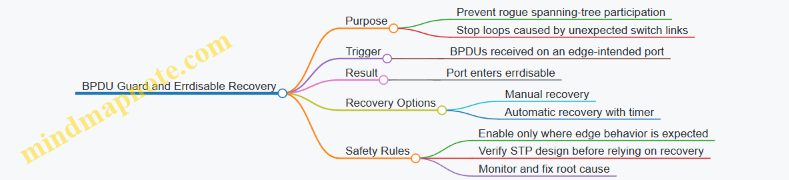
Safe Configuration Strategy
Start by identifying which ports are truly “edge.” A port is edge when it connects to an end device such as a server, workstation, IP phone, or access point uplink that is not expected to run STP. If you’re unsure, treat it as non-edge and avoid BPDU Guard.
Next, enable BPDU Guard on those edge ports. In practice, you’ll usually configure STP edge behavior and BPDU Guard together so the intent is consistent.
Finally, decide how you want recovery to behave. Automatic recovery is convenient, but it can hide a persistent cabling or device problem by repeatedly flapping the port. A safe approach is to use a short recovery timer and pair it with monitoring and a clear operational process.
Example: BPDU Guard on Edge Ports
conf t
! Assume Rapid PVST is in use and edge ports are configured
interface range gigabitethernet1/0/1-1/0/24
 switchport mode access
 spanning-tree portfast
 spanning-tree bpduguard enable
end
This example enables BPDU Guard on access ports that are configured as portfast. If a switch is accidentally connected and starts sending BPDUs, the port will be errdisabled.
Example: Errdisable Recovery for BPDU Guard
conf t
! Enable automatic recovery for BPDU Guard related errdisable events
errdisable recovery cause bpduguard
errdisable recovery interval 300
end
A 300-second interval is long enough for transient issues to settle, but short enough to restore service without manual intervention. If your environment is sensitive to repeated port cycling, reduce the interval only after you’ve confirmed the operational impact.
Verification Steps That Actually Matter
After configuration, verify three things: the port state, the errdisable cause, and the recovery behavior.
- Confirm the portfast and BPDU Guard settings are present on the intended interfaces.
- Confirm the port enters errdisable when BPDUs appear.
- Confirm the port returns to service after the recovery interval.
Use targeted show commands and focus on the specific interface you tested. Broad “show everything” output is noisy and makes it harder to prove correctness.
Troubleshooting Mindset for Real Incidents
When a port errdisables due to BPDU Guard, the root cause is almost always one of these: a switch was connected to an edge port, a patching mistake occurred, or an uplink was configured as if it were an end-host connection.
Do not immediately increase recovery timers as a first response. If the underlying issue persists, the port will keep bouncing. Instead, identify the device on the errdisabled port, confirm cabling, and ensure the correct interface type is used for switch-to-switch links.
Operational Safety Checklist
- Enable BPDU Guard only on ports that should never receive BPDUs.
- Use errdisable recovery when you want automatic restoration, but keep the interval reasonable.
- After any errdisable event, treat it as a signal to correct the topology or cabling, not just a nuisance to wait out.
- Validate on a single port first, then roll out consistently.
Mind Map: Safe Rollout Flow
BPDU Guard gives you a fast, deterministic response to an STP policy violation. Errdisable recovery keeps the network from requiring manual intervention every time that policy is triggered. The safest results come from matching the features to the right ports and treating each errdisable event as a topology correction opportunity.
5.5 Troubleshoot Convergence Delays and Traffic Blackholes
Convergence delays and traffic blackholes often share the same root cause: forwarding state and control-plane state do not agree for long enough to matter. The goal is to prove where the mismatch happens, then shorten the time window or remove the condition that creates it.
Foundational Concepts You Must Verify First
Start with the simplest truth: a blackhole is usually not “no route exists,” but “the device forwards somewhere it shouldn’t, or it refuses to forward until it learns something.” Convergence delay is the time between a topology or policy change and the moment traffic follows the new correct path.
In STP-based Layer 2 networks, blackholes commonly appear during:
- Root changes or role transitions that trigger port state changes.
- Link failures that cause MAC address aging and relearning gaps.
- Trunk misbehavior that makes VLAN membership inconsistent.
In routed networks, blackholes commonly appear during:
- Routing protocol convergence where next hops change before ARP/neighbor resolution stabilizes.
- Policy changes that temporarily remove routes from forwarding.
A Systematic Troubleshooting Workflow
-
Confirm the symptom type
- If traffic fails only for certain VLANs or certain source/destination pairs, suspect VLAN/STP/ACL placement.
- If traffic fails broadly after a link event, suspect STP topology change, routing convergence, or gateway redundancy behavior.
-
Identify the event timeline
- Note the exact moment the failure occurs and when traffic stops/returns.
- Use interface counters and logs to correlate with link up/down or STP topology change events.
-
Verify Layer 2 forwarding readiness
- Check STP port states on the relevant switches. A port stuck in a non-forwarding state is a classic “it converged, but not for you” issue.
- Validate VLAN trunking so the correct VLAN actually reaches the forwarding path.
-
Verify Layer 2 learning behavior
- After topology changes, MAC tables may flush or age out. During relearning, frames can be flooded or dropped depending on port state.
- Look for MAC flaps or unexpected MAC moves that indicate instability.
-
Verify Layer 3 reachability and next-hop resolution
- Confirm routes exist on the forwarding device and that the next hop is reachable.
- Check ARP/neighbor tables for incomplete resolution after the event.
-
Prove where the drop happens
- Use targeted packet tracing or counters on the ingress/egress interfaces.
- If ingress counters increase but egress counters do not, the drop is likely local (ACL, STP state, or missing forwarding entry).
Mind Map: Convergence Delay and Blackhole Causes
Concrete Examples That Match Exam-Style Scenarios
Example 1: STP Port State Causes a VLAN-Specific Blackhole
- Situation: After a switch uplink fails, users in VLAN 20 lose connectivity, but VLAN 10 works.
- What to check: On the switch that becomes the new path, verify the VLAN 20-facing ports are actually forwarding. If VLAN 20 is on a port that is still in a non-forwarding STP state, frames never reach the destination.
- What to fix: Correct the STP topology by ensuring the intended uplink is the one with the correct STP role, and confirm VLANs are present on the trunk.
Example 2: MAC Aging Creates a Temporary Drop Window
- Situation: Connectivity returns after 30–60 seconds, but only for hosts that moved during the event.
- What to check: Compare MAC table entries before and after the event. If entries age out and relearning is slow, traffic may be dropped if the relevant port is not forwarding yet or if flooding is limited.
- What to fix: Stabilize the topology so the same forwarding path remains active, and eliminate link flaps that cause repeated relearning.
Example 3: Routing Converges Before Next-Hop Resolution
- Situation: A routing protocol updates routes quickly, but traffic still fails briefly.
- What to check: Confirm the new route points to a next hop that is reachable at Layer 2. If ARP/neighbor entries are missing, the device may queue or drop until resolution completes.
- What to fix: Ensure the next hop is on a stable adjacency and that the underlying Layer 2 path is correct for the relevant VLAN.
Practical Verification Commands to Use Intentionally
Use show commands to answer specific questions, not to collect random output.
- STP readiness: check port roles and states on the affected switches.
- VLAN correctness: confirm trunk allowed VLANs and native VLAN behavior.
- MAC churn: inspect MAC table changes around the event.
- Route and next hop: verify the route exists and the next hop is reachable.
- ARP/neighbor: confirm resolution completes after the topology change.
Common Root Causes and How They Create Delays
- Inconsistent VLAN trunking makes the “right” path wrong for a VLAN, so traffic never reaches the intended forwarding plane.
- STP role transitions create a period where ports are not forwarding, which directly blocks frames.
- MAC instability forces relearning and can extend the time before correct unicast forwarding resumes.
- Next-hop reachability gaps cause traffic to fail even when routes appear correct.
A good troubleshooting session ends with a clear statement: “Traffic fails because X is not forwarding/learning/resolving at time Y.” Once you can say that precisely, the fix becomes straightforward.
6. Inter VLAN Routing with SVIs and High Availability
6.1 Configure SVIs with Correct VLAN Interfaces
SVI Purpose and Prerequisites
An SVI (Switched Virtual Interface) is the Layer 3 interface for a VLAN on a multilayer switch. It lets you route between VLANs without adding separate routers for each segment. The key prerequisite is simple: the VLAN must exist in the switch, and the SVI must be enabled and reachable.
Start by confirming the switch is actually doing Layer 3 work. On many platforms, that means enabling routing features and ensuring the device supports SVIs. Then confirm your VLAN plan: each VLAN that needs an SVI must have a consistent VLAN ID across the entire switching domain.
Mind Map: SVI Configuration Flow
Configure VLANs and Confirm VLAN Membership
Create the VLANs first, then verify that ports are assigned correctly. If VLAN 10 is your user network, VLAN 10 must be present and must carry traffic from the access ports or trunks that connect to endpoints.
Example workflow:
- Create VLAN 10 and VLAN 20.
- Assign access ports to VLAN 10.
- Configure trunks so VLAN 10 and 20 are allowed end-to-end.
- Verify VLAN membership before touching SVIs.
Create SVIs with Correct IP Addressing
An SVI gateway IP is typically the default gateway for hosts in that VLAN. Choose an IP that matches your addressing plan and avoid duplicates. Also ensure the mask matches the subnet used by endpoints.
Example: SVI for VLAN 10 and VLAN 20
vlan 10
 name USERS
vlan 20
 name SERVERS

interface vlan 10
 description Gateway for USERS
 ip address 10.10.10.1 255.255.255.0
 no shutdown

interface vlan 20
 description Gateway for SERVERS
 ip address 10.10.20.1 255.255.255.0
 no shutdown
A small but important detail: the SVI interface should be administratively up. If it’s shut down, it won’t answer ARP, and hosts will fail to reach other VLANs even though the VLAN exists.
Understand SVI Operational State
SVIs often transition to an operationally up state based on platform behavior and VLAN activity. In practice, you should treat “configured” and “working” as different states.
Use verification to confirm both:
- The VLAN exists.
- The SVI has the expected IP.
- The interface is up/up or at least not administratively down.
Verification Commands That Actually Matter
Run checks in an order that narrows the problem quickly.
- Confirm VLANs:
show vlan brief
- Confirm SVI IPs and interface status:
show ip interface brief
- Confirm ARP is learning:
show arp vlan 10
- Confirm L2 learning is happening:
show mac address-table vlan 10
If ARP is empty for VLAN 10 while hosts are active, the issue is usually one of these: wrong VLAN on access/trunk, SVI shutdown, or IP mismatch.
Common Mistakes and How to Spot Them
VLAN ID Mismatch Across Trunks
If VLAN 10 is allowed on one trunk but not another, the SVI may be correct while traffic never reaches it. The symptom is often “no ARP entries” plus correct-looking IP configuration.
Duplicate Gateway IP
If another device uses the same gateway IP, ARP replies can be inconsistent. You may see flapping ARP entries or intermittent connectivity.
SVI Shutdown or Missing Routing Enablement
Even with correct IPs, an administratively down SVI won’t route. Also ensure the switch is configured to route between interfaces; otherwise, SVIs exist but forwarding won’t occur.
Example: End-to-End Validation with a Simple Test
After SVIs are configured, validate connectivity from a host in VLAN 10 to the gateway and then to VLAN 20.
- Host in VLAN 10 pings
10.10.10.1to confirm local gateway reachability. - Host in VLAN 10 pings
10.10.20.1to confirm inter-VLAN routing. - If the first ping fails, focus on VLAN membership and SVI status.
- If the first ping works but the second fails, focus on routing enablement and any ACLs or policy controls.
Mind Map: Verification and Troubleshooting
Wrap-Up: What “Correct VLAN Interfaces” Means
“Correct VLAN interfaces” means the SVI is bound to the right VLAN ID, has the right IP addressing, is administratively enabled, and is supported by working VLAN membership across the switching fabric. When those pieces align, hosts can ARP for the gateway and routing can forward traffic between VLANs predictably.
6.2 Implement First Hop Redundancy with HSRP or VRRP
First Hop Redundancy With HSRP Or VRRP
First hop redundancy solves a very specific problem: hosts use a default gateway, and if that gateway disappears, traffic stops until hosts learn a new path. HSRP and VRRP keep a virtual gateway IP stable so hosts keep sending to the same address, even while the active router changes.
Foundational Concepts
A typical design has:
- A shared default gateway IP (virtual IP) that hosts use.
- One or more routers on the same L2 segment that participate in the redundancy group.
- A role model: one router forwards traffic (active/master), others wait (standby/backup).
HSRP uses a group number and tracks an “active” router. VRRP uses a virtual router ID and a “master” router. The exam mindset is the same for both: identify the virtual IP, confirm which router is master/active, and verify failover behavior.
HSRP Configuration Workflow
HSRP is commonly deployed on SVIs, so the virtual gateway sits on the same VLAN as the hosts. Use these steps:
- Choose the virtual IP and group number.
- Configure HSRP on each participating SVI.
- Set priorities so one router is preferred.
- Add tracking so the preferred router steps down when a critical condition fails.
- Verify role, timers, and state transitions.
Example scenario: VLAN 10 has hosts with default gateway 10.10.10.1. Two routers connect to VLAN 10 with SVI IPs 10.10.10.2 and 10.10.10.3.
interface Vlan10
 ip address 10.10.10.2 255.255.255.0
 standby 10 ip 10.10.10.1
 standby 10 priority 110
 standby 10 preempt
 standby 10 track 1 decrement 20
!
track 1 interface GigabitEthernet0/0 line-protocol
On the other router, keep the same group and virtual IP, but lower priority.
interface Vlan10
 ip address 10.10.10.3 255.255.255.0
 standby 10 ip 10.10.10.1
 standby 10 priority 100
 standby 10 preempt
 standby 10 track 1 decrement 20
!
track 1 interface GigabitEthernet0/0 line-protocol
Tracking is what makes failover meaningful. If the preferred router loses its uplink, its priority drops and the other router becomes active without waiting for a long timer.
VRRP Configuration Workflow
VRRP follows the same logic but uses virtual router IDs and master election. Configure:
- Virtual IP on each participating SVI.
- VRRP group ID and priority.
- Preempt behavior.
- Tracking to adjust priority.
- Verification of master state.
Example: VLAN 10 virtual gateway remains 10.10.10.1.
interface Vlan10
 ip address 10.10.10.2 255.255.255.0
 vrrp 10 ip 10.10.10.1
 vrrp 10 priority 110
 vrrp 10 preempt
 vrrp 10 track 1 decrement 20
!
track 1 interface GigabitEthernet0/0 line-protocol
On the backup router:
interface Vlan10
 ip address 10.10.10.3 255.255.255.0
 vrrp 10 ip 10.10.10.1
 vrrp 10 priority 100
 vrrp 10 preempt
 vrrp 10 track 1 decrement 20
!
track 1 interface GigabitEthernet0/0 line-protocol
Verification That Actually Matters
Use verification to answer three questions:
- Is the virtual IP present and correct?
- Which router is master/active right now?
- Will failover happen quickly when tracking changes?
HSRP checks often include:
show standby briefto confirm active/standby.show standby vlan 10for timers, priority, and tracking impact.
VRRP checks often include:
show vrrp briefto confirm master.show vrrp vlan 10for state and priority changes.
A practical test: shut down the tracked interface on the preferred router. You should see the role change and the virtual gateway remain the same IP from the host perspective.
Mind Map: First Hop Redundancy with HSRP or VRRP
Common Pitfalls and How to Avoid Them
The most frequent mistake is configuration mismatch: one router uses a different group/ID or virtual IP, which prevents proper election. Another is tracking the wrong thing, such as an interface that flaps during normal operations, causing unnecessary role changes. Finally, confirm that both routers are actually eligible: the SVI must be up, and the participating interface must be in the correct VLAN so the redundancy protocol can exchange state.
When you can clearly state the virtual IP, the current active/master router, and the reason failover will occur, you’re doing the exam-style thinking that leads to correct answers.
6.3 Use GLBP For Load Balancing And Gateway Redundancy
GLBP (Gateway Load Balancing Protocol) lets multiple first-hop routers share a single virtual gateway IP and distribute traffic across them. Unlike HSRP or VRRP, GLBP can actively load-balance by assigning different routers as active forwarders for the same virtual IP. The result is redundancy with less “all traffic goes to one box” behavior.
Foundational Concepts You Must Keep Straight
GLBP uses a virtual IP address (VIP) that hosts use as their default gateway. Routers participating in GLBP are grouped under a GLBP group number and share the same VIP. Each GLBP group elects:
- Active Virtual Gateway (AVG): the router that assigns the virtual MAC addresses and controls load-balancing behavior.
- Standby Virtual Gateway (ASVG): takes over AVG duties if the AVG fails.
- Active Forwarders (AF): routers that actually forward traffic for specific virtual MACs.
Hosts send frames to the VIP’s MAC. GLBP maps that MAC to one of the AF routers, so different hosts can land on different forwarders.
How GLBP Load Balancing Works in Practice
GLBP can use different load-balancing methods. The most common exam-relevant idea is that the AVG hands out multiple virtual MAC addresses, each tied to an AF router. A simple mental model:
- Hosts ARP for the default gateway IP (VIP).
- The AVG responds with a virtual MAC address.
- The selected AF router forwards the traffic.
- The AVG can vary which virtual MAC a host receives, spreading flows.
If you only remember one thing: GLBP load balancing is implemented through multiple virtual MACs for the same VIP.
Configuration Workflow with Integrated Best Practices
Start with a clean baseline: redundant L3 gateways on the same VLAN, consistent addressing, and reachability between routers and the downstream network.
- Choose the VIP and GLBP group. Example: VIP 10.10.10.1/24 on VLAN 10, group 10.
- Assign each router a unique real IP in the same subnet. Example: R1 10.10.10.2, R2 10.10.10.3.
- Enable GLBP on the SVI interface and set the VIP.
- Set the AVG priority so you control who becomes AVG.
- Tune timers and preemption behavior so failover is predictable.
A small but important best practice: keep the GLBP group number and VIP consistent across all participating routers, and ensure both routers can reach the same upstream and downstream networks. If one router can’t forward, you’ll get “redundancy” that still drops traffic.
Example Configuration for Two Routers
Assume VLAN 10 is the user subnet. R1 is intended to be AVG.
! R1
interface Vlan10
 ip address 10.10.10.2 255.255.255.0
 glbp 10 ip 10.10.10.1
 glbp 10 priority 110
 glbp 10 preempt
 glbp 10 load-balancing round-robin

! R2
interface Vlan10
 ip address 10.10.10.3 255.255.255.0
 glbp 10 ip 10.10.10.1
 glbp 10 priority 100
 glbp 10 preempt
 glbp 10 load-balancing round-robin
This uses round-robin distribution so new ARP resolutions can be spread across virtual MACs. In real networks, you might prefer a method that better matches how hosts create sessions, but round-robin is a solid baseline for understanding.
Verification Steps That Actually Tell You Something
Use verification to confirm both role election and forwarder behavior.
show glbp brief
show glbp 10
show arp | include 10.10.10.1
show ip route 0.0.0.0 0.0.0.0
What to look for:
- AVG and ASVG roles appear as expected.
- Active forwarders list multiple routers when load balancing is enabled.
- ARP entries for the VIP show a virtual MAC, and different hosts may map to different virtual MACs.
Mind Map: GLBP Roles and Traffic Flow
Common Exam Pitfalls and How to Avoid Them
- Forgetting that forwarding is per AF router: if one router lacks routes or upstream reachability, GLBP can still hand out its virtual MAC, causing blackholes.
- Mismatched VIP or group number: hosts will ARP, but routers won’t agree on the GLBP instance.
- Assuming GLBP replaces routing: GLBP only handles first-hop gateway behavior; the AF routers still need correct routing and policies.
Practical Reasoning Example with Failure
If R1 (AVG) fails, R2 (ASVG) becomes AVG. Hosts may keep using the previously learned virtual MAC until ARP refresh, but when they re-resolve, the new AVG continues assigning virtual MACs to active forwarders. If both routers remain healthy for forwarding, traffic continues with minimal disruption; if only one router can forward, GLBP still preserves gateway availability, just with reduced load distribution.
6.4 Validate Failover Behavior with Verification Commands
Failover is only “successful” when the network converges quickly enough and the right clients keep working. For first-hop redundancy on SVIs, the most common failure modes are not the switchover itself, but what happens immediately after: ARP entries linger, default gateways change, and traffic may briefly hit the wrong next hop. Verification should therefore be staged: confirm the redundancy state, confirm gateway reachability, confirm host ARP behavior, and confirm traffic forwarding.
Foundational Checks Before You Trigger Anything
Start with a baseline so you can tell “changed” from “already broken.”
- Confirm the SVI and redundancy are up.
show interface vlan <id>should show the interface is up/up.show standby brief(HSRP/VRRP style) should show the current active/primary role.
- Confirm the gateway IPs and virtual IP are correct.
- Verify the virtual gateway address is present in the redundancy configuration.
- Use
show standbyor the equivalent to confirm the virtual IP is bound to the correct VLAN.
- Confirm upstream routing is stable.
- If the gateway is the only path to a destination, route instability can masquerade as failover problems.
Mind Map: Verification Flow for First-Hop Failover
Verify Role Transition with Show Commands
When the primary fails, the standby device should become active and the role should change without ambiguity.
- On both routers, run:
show standby briefshow standby
- Look for:
- The active/primary role moving to the expected peer.
- Timers behaving as expected (for example, you should see the transition after the configured hold/priority logic).
- No unexpected “stuck” states where both devices claim active.
A practical habit: capture output from both devices before the trigger, then again immediately after. If only one side shows a change, you may be watching the wrong VLAN or the wrong redundancy group.
Verify Gateway Reachability from Hosts
Role change alone doesn’t prove traffic success. Verify from at least two hosts in the VLAN: one that is actively sending and one that is idle.
- From a host, validate default gateway:
- Check the host’s default route points to the virtual IP.
- Test reachability:
ping <remote-ip>where<remote-ip>is across the network.- If you can, run a continuous ping during the trigger to observe packet loss patterns.
- Confirm next hop behavior:
traceroute <remote-ip>should show the virtual gateway as the first hop.
If pings fail but traceroute still shows the correct first hop, the issue is likely forwarding or ARP, not the default gateway configuration.
Verify ARP and Gratuitous ARP Behavior
After failover, hosts may still have an ARP entry mapping the virtual IP to the old MAC address. Many designs rely on gratuitous ARP to refresh host caches.
On the routers:
- Use
show arpto confirm the virtual gateway MAC is associated with the correct peer behavior. - Use
show mac address-table vlan <id>to confirm the switch learns the expected MAC on the correct ports.
On the host:
- Re-check ARP resolution by running a ping after the failover and observing whether ARP entries update.
If you see repeated ARP misses or stale mappings, you may need to confirm that the redundancy configuration supports the expected ARP refresh behavior and that the SVI is still forwarding.
Verify Forwarding with Interface and Counter Checks
To avoid guessing, check counters around the time of failover.
On the active and standby routers:
show interface vlan <id>for input/output errors and drops.show interface counters errorsor interface-specific counters to spot spikes.- If available in your platform, check redundancy-specific counters or logs for transition events.
On the switching layer:
show mac address-table vlan <id>before and after to ensure MAC movement is reasonable.
A quick sanity test: if the MAC table flips rapidly back and forth, you likely have flapping links or an STP-related issue that coincides with the failover.
Example: Command Sequence for a Controlled Failover
# On Both Routers, Capture Baseline
show interface vlan 10
show standby brief
show standby
show arp | include 10.

# Trigger Failure on the Primary
# Example: disable the uplink interface

# Immediately After
show standby brief
show standby
show interface vlan 10
show arp | include 10.

# From a VLAN 10 host
ping <remote-ip>
traceroute <remote-ip>
Common Verification Outcomes and What They Mean
- Role changes correctly, host pings succeed: failover behavior is healthy.
- Role changes correctly, host pings fail briefly then recover: ARP refresh or transient forwarding delay is likely.
- Role changes incorrectly or both devices show active: redundancy configuration mismatch or timer/priority logic issue.
- Role changes correctly, traceroute first hop is correct, but pings never succeed: forwarding path or ACL/security policy is blocking traffic.
Treat verification as a checklist with evidence. When you can point to the exact command outputs that changed and the exact moment traffic recovered, you stop relying on “it seems fine” and start relying on proof.
6.5 Troubleshoot Gateway Failover and ARP Instability
Gateway failover issues often look like “routing is fine, but hosts can’t talk.” The usual culprit is not routing itself—it’s the local gateway behavior on the first hop, plus how quickly hosts update their ARP entries. When ARP and first-hop redundancy disagree on timing, you get intermittent blackholes.
Foundational Concepts That Drive the Symptoms
First, identify what “gateway” means in your design. With SVIs, the default gateway for each VLAN is the SVI IP on the active router. With HSRP or VRRP, multiple routers share a virtual IP, but only one is active at a time.
Second, remember what ARP does. Hosts cache the MAC address for the gateway IP. If the active gateway changes, the gateway IP stays the same, but the gateway MAC changes. Hosts keep using the old MAC until their ARP entry expires or they receive an ARP update that forces a refresh.
Third, distinguish two failure phases:
- Failover convergence: the redundancy protocol elects a new active router and updates forwarding.
- Host ARP convergence: hosts learn the new gateway MAC.
If failover happens faster than host ARP refresh, traffic can hit the wrong MAC for a short window. If failover is slow or flapping, ARP instability can persist.
Step by Step Troubleshooting Workflow
-
Confirm the redundancy state on both routers
- Check whether the standby actually became active.
- Verify timers and preemption behavior so you know whether the active should stay put.
-
Verify SVI and forwarding health
- Ensure the SVI is up/up on the active router.
- Confirm VLAN membership and trunking so the active router can receive frames for that VLAN.
-
Measure the timing gap between failover and ARP refresh
- On a switch or router, watch ARP table changes for the gateway IP.
- On a host, check ARP cache age if your platform supports it.
- If ARP entries remain stale long enough, you’ll see drops even though the new gateway is ready.
-
Look for ARP flux causes ARP flux happens when multiple devices answer for the same IP with different MACs. In gateway failover designs, this can occur if:
- Both routers briefly believe they are active.
- One router still forwards for the virtual IP while another is already answering.
- A misconfiguration causes the virtual IP to be present on an unexpected interface.
-
Validate that only the active router answers for the virtual IP
- Confirm the virtual IP is tied to the redundancy process, not manually configured on both SVIs.
- Ensure the standby does not respond to ARP for the virtual IP.
-
Check for L2 side effects
- STP changes can move the SVI’s connected path, causing transient loss that looks like gateway failure.
- MAC address table churn on access switches can amplify the problem.
Mind Map: Gateway Failover and ARP Instability
Concrete Examples with Reasoning
Example 1: Failover happens, but hosts still fail for 30–60 seconds
- Observation: After the active router fails, the new active is correct, but clients keep sending to the old gateway MAC.
- Reasoning: Hosts update ARP only when their cache expires or when they receive ARP replies that trigger refresh.
- Fix approach: Shorten the window by tuning redundancy timers so failover is decisive, and ensure host-facing L2 is stable so the new gateway’s MAC is learned quickly.
Example 2: ARP table shows rapid MAC changes for the same gateway IP
- Observation: The gateway IP maps to different MAC addresses repeatedly.
- Reasoning: That’s classic ARP flux. Two devices are answering for the virtual IP, or the active role is oscillating.
- Fix approach: Verify that only the active redundancy instance owns the virtual IP, correct any duplicate IP configuration on SVIs, and check health-check logic that might cause frequent active/standby transitions.
Example 3: Gateway failover is correct, but only one VLAN works
- Observation: One VLAN’s clients recover quickly; another VLAN’s clients don’t.
- Reasoning: The new active may be forwarding for one SVI but not the other due to VLAN trunking, missing VLAN allowed lists, or an SVI that is down.
- Fix approach: Confirm trunk allowed VLANs, verify SVI operational state, and re-check that the affected VLAN path is stable during failover.
Practical Verification Commands to Use in the Right Order
Use a sequence that prevents you from chasing ghosts.
show standby brief
show standby vlan
show interfaces vlan <vlan-id>
show arp | include <virtual-ip>
show mac address-table vlan <vlan-id>
If ARP changes are frequent, focus on redundancy state transitions first. If ARP changes are rare but traffic still fails, focus on host ARP staleness and L2 stability.
Quick Checklist for Exam Style Scenarios
- Virtual IP is owned by redundancy, not manually duplicated.
- Standby becomes active exactly once per event.
- SVI is up/up on the active router for the affected VLAN.
- ARP for the virtual IP updates on the network side when failover occurs.
- Switch MAC learning does not churn due to STP or trunk issues.
When you treat failover and ARP refresh as two separate clocks, troubleshooting becomes much more deterministic. You stop guessing and start measuring which clock is late.
7. Network Services with DHCP DNS and IP Address Management
7.1 Configure DHCP for IPv4 With Pools and Options
DHCP for IPv4 hands out IP addresses and key network parameters automatically, so hosts don’t need manual configuration. On an enterprise network, you typically run DHCP on a server or on a router/SVI, then scope addresses into pools that match VLANs or subnets. The exam-friendly goal is simple: make sure the right clients receive the right addresses with the right options, and verify it with targeted show commands.
Core Concepts Before You Touch Commands
A DHCP server maintains a database of leases. When a client boots, it broadcasts a DHCPDISCOVER message. The server responds with DHCPOFFER, the client requests with DHCPREQUEST, and the server confirms with DHCPACK. The lease has a start time and an expiration time, and the client renews before it expires.
A DHCP pool defines the address range and the subnet mask. Options define what else the client should learn, such as the default gateway, DNS servers, and domain name. If you forget an option, clients may still get an IP address but fail to reach the network or resolve names—classic “it’s working, until it isn’t” behavior.
Designing Pools That Match Your Subnets
Start by mapping each VLAN/subnet to a DHCP pool. For example, VLAN 10 might be 10.10.10.0/24 for users, VLAN 20 might be 10.10.20.0/24 for servers, and each gets its own pool. Keep the pool range away from addresses you reserve for infrastructure devices (gateways, switches, printers, and network appliances).
A practical rule: reserve the first few IPs in the subnet for static devices, then start the pool at a higher address. If your gateway is 10.10.10.1, you might start the pool at 10.10.10.50 and end at 10.10.10.200.
Configuring a DHCP Pool with Essential Options
Below is a typical router-based DHCP configuration for one subnet. Replace interface names and addresses to match your lab.
ip dhcp excluded-address 10.10.10.1 10.10.10.49
ip dhcp pool VLAN10-USERS
 network 10.10.10.0 255.255.255.0
 default-router 10.10.10.1
 dns-server 10.10.10.53 10.10.10.54
 domain-name corp.example
 lease 7
The excluded-address range prevents the server from assigning critical static addresses. The pool name is just an identifier, but the network and mask must match the subnet you intend to serve. The default-router option is the gateway the client uses for off-subnet traffic. DNS servers and domain name let clients resolve hostnames without manual edits.
Adding Options Without Breaking Clients
DHCP options can be layered, but you should only configure what your clients need. Common options include:
- Default gateway: required for most networks.
- DNS servers: required for name resolution.
- Domain name: helps clients form FQDNs.
- Lease time: shorter leases help faster changes during troubleshooting.
If you configure DNS incorrectly, clients may still obtain an IP address and ping the gateway, yet fail to resolve names. That’s why verification matters.
Mind Map: DHCP Pools and Options
Verification That Actually Proves the Right Outcome
After configuration, verify that the server is offering addresses and that clients receive the expected options. On Cisco IOS, use these checks:
- Confirm the pool exists and matches the subnet.
- Confirm excluded addresses are applied.
- Confirm active leases.
show ip dhcp pool VLAN10-USERS
show ip dhcp binding
show running-config | section ip dhcp
If you see no bindings, either no clients are requesting, the pool doesn’t match the client’s subnet, or DHCP isn’t reachable (for example, missing relay on a different VLAN). If bindings exist but clients can’t reach DNS, re-check dns-server and domain-name values.
Example Scenario with Clear Reasoning
Imagine VLAN 10 users get IP addresses, but web browsing fails while ping to the gateway works. That pattern points to routing being fine and name resolution failing. The fastest fix is to verify the DHCP options delivered to clients: confirm dns-server values match reachable DNS servers from the client subnet. If the DNS server is 10.10.10.53, but you accidentally configured 10.10.10.35, the client will still receive an IP and gateway, yet name lookups will fail.
Once you correct the DNS option, new DHCP leases (or a client renewal) should start returning the correct resolver addresses. Then you can re-check bindings and confirm the client behavior aligns with the corrected configuration.
7.2 Configure DHCP Relay and Verify Broadcast Forwarding
When a client needs an IP address, DHCP uses broadcast messages to reach a server. In a routed enterprise network, broadcasts don’t cross Layer 3 boundaries, so the client’s broadcast stays trapped in its local VLAN. DHCP relay fixes that by forwarding DHCP messages to a configured DHCP server, while still letting the server respond as if it were talking to the client’s subnet.
Core Concepts You Need Before Touching Config
DHCP relay on a router or Layer 3 switch listens for DHCP client messages on one interface (the client side) and forwards them to the DHCP server on another interface (the server side). Two details matter for correctness:
- Which interface the relay listens on: Typically the SVI or routed interface where clients live.
- Which source information the relay includes: The relay must preserve the client subnet context so the server can choose the right pool.
A practical way to remember it: relay is the “mailroom clerk” that accepts a broadcast letter, then sends it to the right server address with the correct return address.
Mind Map: DHCP Relay and Broadcast Forwarding
Configuration Approach That Avoids Guesswork
- Confirm the client VLAN interface: Identify the SVI or routed interface where clients send DHCP broadcasts.
- Confirm the DHCP server reachability: Ensure the relay device can route to the server IP.
- Configure relay per VLAN interface: Apply relay on the interface that receives client broadcasts.
- Verify with packet counters and DHCP server logs: You want evidence at both ends.
Example: Configure DHCP Relay on an SVI
Assume:
- Clients are on VLAN 10 (SVI
Vlan10) - DHCP server is
192.0.2.50 - Relay device is the default gateway for VLAN 10
interface Vlan10
 ip address 192.0.2.1 255.255.255.0
 ip helper-address 192.0.2.50
That single line is the core behavior: it tells the device to forward DHCP messages it receives on Vlan10 to the server.
Example: Verify Relay Is Receiving and Forwarding
Use these verification steps in order:
- Check interface state
show ip interface brief
show interfaces vlan 10
- Confirm relay configuration
show running-config interface vlan 10
- Watch DHCP-related counters
show ip dhcp relay
show ip dhcp relay statistics
If your platform doesn’t show the exact commands above, the idea is the same: look for relay statistics that indicate forwarding activity.
Verifying Broadcast Forwarding End-to-End
Verification should prove three things: the relay sees the client’s DHCP attempt, the server receives it, and the client receives a response.
Step 1: Generate a Controlled DHCP Request
On a test client in VLAN 10, clear the lease and request a new one. You’re looking for a DHCP Discover/Request cycle.
Step 2: Confirm Relay Activity
On the relay device, check that relay statistics increment during the client request window. If counters don’t move, the relay isn’t receiving the broadcast on that interface.
Step 3: Confirm Server Side Receipt
On the DHCP server, confirm it logs a request from the relay agent context. The server should select the pool that matches VLAN 10’s subnet.
If the server assigns an address from the wrong pool, the relay isn’t providing the correct client subnet context, or the server’s pool mapping doesn’t match the relay’s expectations.
Step 4: Confirm Client Receives the Offer and Lease
On the client, verify:
- It receives an IP address from the VLAN 10 pool
- It receives the correct default gateway (usually the relay device’s SVI IP)
- It can reach the DHCP server and gateway (basic sanity)
Common Mistakes and Fast Checks
- Relay configured on the wrong interface: Clients broadcast on VLAN 10, but relay is configured on VLAN 20. Fix by applying
ip helper-addressto the SVI that receives client DHCP. - Wrong DHCP server IP or VRF: Relay forwards to an unreachable or incorrect server. Fix by confirming routing/VRF context and server IP.
- ACLs blocking DHCP traffic: If UDP 67/68 or relay forwarding is filtered, the server never responds. Fix by allowing relay-to-server traffic and server-to-client return paths.
Quick Verification Checklist
- Client VLAN interface is up and correct
ip helper-addresspoints to the correct DHCP server- Relay statistics increase during client DHCP attempts
- DHCP server logs show requests and correct pool selection
- Client receives a lease with the expected gateway and subnet
7.3 Configure DNS Forwarding and Validate Name Resolution
DNS forwarding lets a router act as a local DNS relay for clients that are configured to use it. Instead of every host learning multiple external DNS servers, the router forwards queries upstream and returns answers. This is especially useful in enterprise networks where clients point to a single “inside” resolver.
Foundational Concepts That Matter
A DNS query has two key parts: the name being asked for and the query type (A for IPv4, AAAA for IPv6, CNAME for aliases, and so on). When forwarding is enabled, the router receives the query from a client, checks whether it can answer locally, and if not, forwards the query to configured upstream servers.
Two practical details prevent most exam and lab mistakes:
- Forwarding is not the same as recursion. The router forwards queries to its upstream resolvers; the upstream resolver performs the heavy lifting.
- Name resolution depends on reachability. If the router cannot reach the upstream DNS server, forwarding fails even if DNS is “configured correctly.”
Configure DNS Forwarding
On Cisco IOS, DNS forwarding is typically configured by specifying upstream DNS servers and enabling the router to relay client queries. The exact commands vary by platform and feature set, but the workflow is consistent.
Step 1: Assign Upstream DNS Servers
Choose DNS servers that are reachable from the router’s routing table. In a lab, it’s common to use a single upstream resolver IP. In production, you often use two for redundancy.
Step 2: Ensure Clients Use the Router
Clients must point their DNS server setting to the router’s inside interface IP (the one that receives DNS queries). If clients still point directly to public DNS servers, forwarding won’t be used.
Step 3: Confirm Routing to Upstream DNS
If the router forwards queries to an upstream DNS server on a different subnet, you need correct routing and, if applicable, ACL permissions. A classic failure mode is “DNS is configured, but nothing resolves,” caused by missing routes or blocked UDP/TCP 53.
Validate Name Resolution Systematically
Validation should be ordered: first confirm the router is receiving queries, then confirm forwarding, then confirm the final answer.
Step 1: Verify the Router Can Reach Upstream DNS
Use a reachability check to the upstream DNS server IP. If the router can’t reach it, DNS forwarding is a dead end.
Step 2: Verify the Router Receives Client Queries
Generate a DNS lookup from a client and watch the router for DNS-related counters or logs. You want to see evidence that queries arrive at the router.
Step 3: Verify Forwarding and Returned Answers
Perform the same lookup and confirm the router returns a valid answer to the client. If the client receives “server not responding” or “name not found,” you need to determine whether the failure is forwarding-related or upstream-related.
Step 4: Use Targeted Tests
Test both an A record name (like www.example.com) and a name that is likely to involve a CNAME chain. This helps you distinguish “no forwarding” from “forwarding works but upstream resolution fails.”
Mind Map: DNS Forwarding and Validation
Example: End-to-End Verification in a Lab
Assume a client is configured with DNS server 192.168.10.1 (the router inside interface). The router forwards to upstream DNS server 203.0.113.53.
- From the client, run a lookup for
www.example.com. - On the router, confirm that DNS queries are being received and that forwarding attempts occur.
- Confirm the client receives an IPv4 address (A record). If it returns an error, check reachability to
203.0.113.53and ensure DNS traffic is permitted. - Repeat with a name that typically uses CNAME indirection. If the A record works but CNAME-based resolution fails, the issue is usually upstream behavior or filtering, not forwarding mechanics.
Example: Diagnosing “Configured but Not Working”
If you can reach the upstream DNS server IP but clients still fail to resolve names, the most common causes are:
- Clients are pointing to a different DNS server than the router.
- The router’s forwarding feature is enabled but the query path is blocked by an ACL on the inside interface.
- The router is forwarding from the wrong VRF or interface context, so it cannot use the expected routing table.
A quick sanity check is to verify the client’s DNS server setting and then confirm that the router sees the query arriving on the correct interface.
7.4 Integrate DHCP and DNS With Consistent Addressing
Consistent addressing means a host’s IP address, name, and reachability line up across DHCP and DNS. If DHCP hands out an address that DNS doesn’t know about, troubleshooting becomes a scavenger hunt. If DNS has a record for an address that DHCP no longer uses, clients may connect to the wrong place. The goal is simple: make DHCP and DNS agree on what “this name lives at this IP” means.
Foundational Concepts That Must Match
Start with the DHCP scope design. A scope defines the address pool, default gateway, DNS server addresses, and lease behavior. DNS design defines how names map to addresses: forward lookups (name to IP) and reverse lookups (IP to name). Consistency requires that the DNS server(s) used by clients are authoritative for the zones that contain those names.
A practical rule: the DHCP option that tells clients which DNS servers to use must point to the same DNS infrastructure that will store the records for those clients. Otherwise, clients will query DNS that can’t answer, even if DHCP is perfectly configured.
How DHCP and DNS Work Together
There are two common integration patterns.
-
DHCP creates DNS records at lease time. When a client requests an address, DHCP can update DNS so the hostname and IP are registered automatically.
-
DHCP provides the IP and clients update DNS themselves. This can work, but it depends on client behavior and permissions. For exam-style troubleshooting, the first pattern is easier to reason about because the server is the source of truth.
In both patterns, the key inputs are the client identifier and the hostname. DHCP uses fields like the hostname option and client identifier to decide whether it should create or update a record. DNS uses the fully qualified domain name (FQDN) and the record type (A/AAAA for forward, PTR for reverse).
Mind Map: Integration Points and Failure Modes
Step-by-Step Best Practices with Examples
1) Make DHCP Tell Clients the Right DNS
Configure DHCP so clients learn the DNS server IP addresses via DHCP options. Example scenario: your DHCP server is 192.0.2.10, and your DNS server is 192.0.2.53. If DHCP hands out addresses in 192.0.2.0/24, clients should receive DNS server 192.0.2.53.
Easy-to-spot mistake: DHCP points clients to a “public” resolver or an internal DNS that doesn’t host the relevant zone. Symptom: clients can reach the network but name resolution fails or returns unrelated answers.
2) Ensure Hostnames Are Stable and Mapped Correctly
If a client changes its hostname between renewals, DHCP may create multiple DNS records. For example, a laptop might request “laptop-01” on first boot and “laptop-01.office” later. Decide on a naming convention and enforce it.
A practical approach is to standardize on FQDN format in DHCP registration. If your domain is example.com, store records as hostnames like host1.example.com rather than relying on clients to append the domain correctly.
3) Register Forward and Reverse Records
Forward records (A) help most users. Reverse records (PTR) matter for diagnostics and some security checks. Example: if a syslog server logs by hostname, reverse lookups can confirm whether the IP-to-name mapping matches the expected host.
Consistency check: for an IP like 192.0.2.25, the DNS reverse zone should contain a PTR record pointing to host1.example.com, and the forward zone should contain an A record for host1.example.com pointing back to 192.0.2.25.
4) Control Lease and Record Lifetimes
DHCP leases and DNS TTLs should align closely enough to avoid long-lived mismatches. If DHCP leases expire quickly but DNS TTL is long, clients may keep using stale answers after an address is reassigned.
Example: set a DHCP lease of 1 hour and a DNS TTL of a similar order (not necessarily identical). When the lease ends, the next client that receives the same IP should trigger an update so the name-to-IP mapping changes promptly.
Verification Workflow That Prevents Guesswork
- Confirm DHCP lease details for the client IP and hostname.
- Query DNS for the forward A record of the FQDN.
- Query DNS for the PTR record for the IP.
- Compare the results to ensure they match exactly.
- If they don’t, check whether DHCP is updating DNS at all, whether it is using the expected hostname field, and whether the DNS server is authoritative for the zone.
Example: Consistency Check in Practice
Suppose a client receives 192.0.2.25 with hostname host1. The DNS forward zone should have:
- host1.example.com A 192.0.2.25
The reverse zone for 192.0.2.0/24 should have:
- 25 PTR host1.example.com
If the forward record exists but the PTR is missing, you still have partial consistency. If the PTR points to a different name, you have a mismatch that can mislead troubleshooting and logging.
Common Exam-Style Pitfalls
- DHCP DNS options point to the wrong DNS server.
- DHCP updates DNS using a hostname that doesn’t match the FQDN format in DNS.
- Reverse zone is not configured, or PTR updates are disabled.
- TTL is too high relative to lease time, causing stale answers after reassignment.
Consistent addressing is less about “turning on integration” and more about making sure the same identity inputs and time expectations flow through both DHCP and DNS.
7.5 Troubleshoot Lease Issues and Resolution Failures
Lease problems usually show up as “clients can’t reach the network” or “clients get an address but can’t resolve names.” The fastest way to avoid guesswork is to separate the problem into three layers: DHCP delivery, IP usability, and DNS resolution. Then you verify each layer with the smallest set of commands that proves or disproves the hypothesis.
Foundational Checks for Lease Failures
Start by confirming the DHCP role and scope behavior on the server or relay path.
- Confirm the client is actually requesting DHCP. On a switch or router, check interface counters and relay configuration. If the client never sends DHCPDISCOVER, you’ll chase ghosts.
- Confirm the relay path is correct. If clients are on a different subnet, the relay must forward broadcasts to the correct DHCP server. A wrong
ip helper-addressmeans the server never sees the request. - Confirm the scope has available addresses. Exhausted pools cause NAK-like behavior or repeated requests. Verify pool state and whether the server is configured to exclude the client’s expected range.
A simple example: a branch VLAN was moved to a new subnet, but the DHCP pool still matches the old network. Clients will keep requesting addresses, and the server will either refuse or hand out something unusable.
Verify DHCP Offer and Lease Assignment
Once you know the request reaches the server, focus on the offer and lease lifecycle.
- Check for repeated DHCPDISCOVER/REQUEST cycles. Repetition suggests the client never receives a valid OFFER or never completes the ACK.
- Validate the lease parameters. If the server hands out an address but the client can’t use it, the issue is often gateway, mask, or DNS options.
- Look for conflicts. If a client receives an address that’s already in use, it may detect conflict and restart DHCP. Conflicts can come from stale static assignments or another DHCP server.
Practical example: a DHCP pool provides the correct IP but sets the wrong default gateway. The client can ping its own IP (sometimes) but fails to reach anything outside the subnet.
Diagnose Resolution Failures After Addressing Works
If the client gets an IP address but name resolution fails, DHCP is still involved because it typically delivers DNS server information.
- Confirm the client received DNS server addresses from DHCP. If DNS is missing or incorrect, the client will fail to resolve FQDNs even though IP connectivity might work.
- Check DNS reachability. Even correct DNS server IPs won’t help if routing or ACLs block UDP/TCP 53.
- Validate search domains and suffix behavior. A wrong domain can make short names fail while FQDNs still work.
Example: users type fileserver and it fails, but fileserver.example.local works. That points to a search domain mismatch delivered via DHCP options.
Mind Map: Lease Issues and Resolution Failures
Systematic Troubleshooting Workflow
Use a tight loop: prove the next link in the chain, then move forward.
- Confirm DHCP exchange behavior. If the client keeps restarting DHCP, focus on delivery path and scope matching.
- Confirm the lease details on the client. Compare the received IP, mask, gateway, and DNS servers against the intended design.
- Test IP reachability by role. Ping the default gateway first. If that fails, the gateway or mask is wrong, or ARP is blocked.
- Test DNS separately from routing. Ping the DNS server IP. If that works but DNS queries fail, check ACLs and DNS server configuration.
- Check for conflicts and duplicates. If the lease keeps changing or the client reports conflicts, look for overlapping DHCP pools or static IPs.
Example: Wrong Helper Address on a Relay
- What you see: Clients on VLAN 20 never get an address; they keep requesting.
- What you verify: Relay configuration on the SVI or interface facing VLAN 20.
- What you fix: Update
ip helper-addressto the correct DHCP server IP for VLAN 20. - What you confirm: Clients receive an OFFER and then an ACK, and the lease appears in the server’s active list.
Example: DNS Option Delivered Incorrectly
- What you see: Clients receive an IP and can ping the gateway, but
ping google.comfails. - What you verify: DHCP options on the server and the DNS server IPs received by the client.
- What you fix: Correct the DNS server addresses and ensure the DHCP pool applies to the client’s subnet.
- What you confirm: Name resolution works without changing IP addressing.
Resolution Failures Checklist
When you’re done, you should be able to answer three questions with evidence: Did the DHCP request reach the correct server? Did the client receive correct IP parameters? Did the client receive reachable DNS servers? If any answer is “no,” the fix is usually straightforward and localized to one component rather than the entire network.
8. Network Security with ACLs and Segmentation
8.1 Design ACL Strategy for Inbound and Outbound Control
An ACL strategy starts with one decision: where traffic is filtered in the path. In Cisco environments, the most common pattern is to filter at the edge of a trust boundary (inbound on the interface facing the untrusted side) and to apply narrower, intent-based rules closer to the resource being protected. The exam expects you to reason about direction, placement, and rule order, not just memorize syntax.
Core Principles for Inbound and Outbound Control
First, remember that ACL direction is relative to the interface. “Inbound” means packets entering the interface; “outbound” means packets leaving it. If you place an ACL on a VLAN SVI, inbound rules govern traffic destined to that SVI and transit traffic entering the switch from that VLAN, while outbound rules govern traffic leaving the SVI toward that VLAN.
Second, design for predictable outcomes. ACLs are processed top-down, and the first match wins. That means your rule order should reflect your most common and most specific matches first, with a final “deny” (or “permit any” if the policy requires it) at the end.
Third, keep rules readable. Named ACLs and consistent object naming reduce mistakes during verification. A rule that says “permit tcp any host 10.10.10.10 eq 443” is precise, but it’s also easy to misread later; pairing it with a clear name and grouping related lines helps.
Mind Map: Inbound Versus Outbound Placement
Building an ACL Plan Step by Step
-
Define the traffic flows. Write down which sources should reach which destinations and on which protocols/ports. For example, “HR users can access the payroll app on TCP 443; everyone else is blocked.”
-
Choose the direction based on intent. If the goal is “only allow HR to reach the server,” inbound on the server-facing interface is usually clean. If the goal is “HR can only talk to the server and not to other subnets,” outbound on the HR-facing interface can be more direct.
-
Select the ACL type and scope. Standard ACLs filter by source only, so they’re rarely ideal for inbound/outbound control where destination and port matter. Extended ACLs support protocol and port matching, which is what you need for realistic enterprise policies.
-
Write the rules in a stable order. Start with permits that represent allowed business traffic, then add denies for known-dangerous patterns (like blocking Telnet), and finish with a final deny if the policy is “default deny.”
Example: Inbound Control on the Server-Facing Interface
Assume a server subnet 10.10.20.0/24 hosts a web app at 10.10.20.10. HR users are 10.10.10.0/24. You want to allow HR to reach TCP 443 and block everything else to that server.
ip access-list extended HR_TO_PAYROLL
 permit tcp 10.10.10.0 0.0.0.255 host 10.10.20.10 eq 443
 deny ip any host 10.10.20.10
 permit ip any any
Apply it inbound on the interface that receives traffic from the HR side toward the server. The key exam detail is that the ACL direction must match the interface where the traffic enters.
Example: Outbound Control on the HR-Facing Interface
Now enforce that HR can only access the payroll server and cannot initiate other connections to the server subnet. This is outbound control from the HR segment.
ip access-list extended HR_OUTBOUND
 permit tcp 10.10.10.0 0.0.0.255 host 10.10.20.10 eq 443
 deny ip 10.10.10.0 0.0.0.255 10.10.20.0 0.0.0.255
 permit ip any any
This rule set is intentionally simple: it permits the one required flow, denies the rest of HR-to-server-subnet traffic, and then allows other unrelated traffic per the broader policy.
Verification That Actually Matches the Strategy
After applying an ACL, check counters to confirm which lines match. If HR users can’t reach 10.10.20.10:443, you want to know whether the permit line is being hit or whether the deny line is catching the traffic earlier. Also verify interface placement and direction; a correct ACL with the wrong direction is a classic “everything looks fine” failure.
Finally, test with targeted traffic. Use one allowed flow (HR to 10.10.20.10 TCP 443) and one disallowed flow (HR to 10.10.20.10 TCP 23). If the allowed flow increments the permit counter and the disallowed flow increments the deny counter, your inbound/outbound strategy is doing what you designed.
8.2 Configure Standard Extended and Named ACLs
ACLs filter traffic based on match conditions, then apply an action. The exam-friendly way to think about them is: match logic first, action second, and placement always. A packet either matches a rule and stops, or it keeps scanning until it hits the implicit deny at the end.
Foundational Concepts for ACL Behavior
An ACL is an ordered list of entries. Each entry has a sequence number, a match criteria, and an action (permit or deny). Cisco devices evaluate entries from lowest sequence number to highest. If no entry matches, the device applies the implicit deny, which is why “it still doesn’t work” often means “you never matched.”
Placement determines direction and scope. Standard ACLs are typically applied close to the source and filter by source IP only. Extended ACLs can match source and destination IP, Layer 4 ports, and protocols, so they are usually applied closer to the destination.
Named ACLs make sequence management easier because you can insert, remove, or reorder entries without renumbering everything. Standard ACLs can be named too, and extended ACLs benefit even more from naming because they often grow into longer rule sets.
Standard ACLs for Source-Based Filtering
A standard ACL matches only the source IP address (and optionally wildcard). Use it when you only need to block or allow traffic based on where it comes from.
Example: Block a user subnet from reaching the server subnet, but you don’t care about the destination details.
ip access-list standard BLOCK_USERS
 permit 10.10.0.0 0.0.255.255
 deny   10.20.0.0 0.0.255.255
 permit any
In this example, traffic from 10.20.0.0/16 is denied regardless of destination. Traffic from 10.10.0.0/16 is allowed. Everything else is permitted by the final explicit permit any, which overrides the implicit deny.
Extended ACLs for Protocol and Port Control
Extended ACLs match protocol plus optional source/destination IP and ports. This is where you stop treating ACLs like blunt instruments.
Example: Allow HTTP and HTTPS from a management subnet to a server, but deny everything else.
ip access-list extended MGMT_TO_WEB
 permit tcp 10.30.10.0 0.0.0.255 host 192.0.2.50 eq 80
 permit tcp 10.30.10.0 0.0.0.255 host 192.0.2.50 eq 443
 deny   ip  10.30.10.0 0.0.0.255 any
 permit ip  any any
The first two lines match TCP with destination port 80 and 443. The third line denies any other IP traffic from the management subnet. The last line permits all other traffic, which is a common lab pattern for isolating the effect of your rules.
Named ACLs and Sequence Numbers
Named ACLs are easier to maintain because you can add entries at specific sequence numbers. This matters when you discover a missing exception and need to insert it without rewriting the whole list.
Example: Insert a new rule before the deny.
ip access-list extended MGMT_TO_WEB
 10 permit tcp 10.30.10.0 0.0.0.255 host 192.0.2.50 eq 80
 20 permit tcp 10.30.10.0 0.0.0.255 host 192.0.2.50 eq 443
 25 permit tcp 10.30.10.0 0.0.0.255 host 192.0.2.50 eq 22
 30 deny   ip  10.30.10.0 0.0.0.255 any
 40 permit ip  any any
Now SSH is allowed in addition to web traffic. The deny still blocks everything else from that subnet.
Placement and Verification
Apply ACLs on the correct interface and in the correct direction. For inbound filtering, use ip access-group NAME in on the interface that receives the traffic.
Verification is not optional. Use counters to confirm matches and show access-lists to review hit counts.
Example verification checklist:
- Confirm the ACL name and entries are correct.
- Confirm the ACL is applied to the intended interface and direction.
- Generate traffic that should match each rule.
- Check hit counters to ensure the expected rule is the one being hit.
Mind Map: Standard Versus Extended ACLs
Practical Design Rules That Prevent Common Mistakes
Start with the smallest set of permits you truly need, then add targeted denies, then decide whether you want an explicit final permit any or rely on implicit deny. If you rely on implicit deny, remember that it denies everything not matched, including traffic you might have forgotten to permit. Finally, keep standard ACLs simple and extended ACLs specific; mixing “source-only” intent with “service-level” requirements is how ACLs end up blocking the wrong thing.
8.3 Implement ACLs With Object Groups for Manageability
Object groups let you name a set of related match criteria—IP addresses, prefixes, or ports—and then reference that name inside ACL rules. Instead of repeating long lists in multiple ACLs, you centralize the list once and reuse it. The exam-friendly goal is simple: fewer copy-paste errors, faster updates, and clearer intent when you read the policy later.
Foundational Idea: Separate “What” From “Where”
Think of object groups as the “what” (the members to match) and ACL entries as the “where” (the direction, protocol, and action). This separation matters because the same source group might be used across several ACLs, while the destination group might change independently.
A practical example: you have a “NOC-Admins” group containing a few management IPs. You want to allow SSH to multiple devices, but only from those admin IPs. With object groups, you update the admin IP list once rather than editing every ACL.
Designing Object Groups Systematically
Start by grouping by intent, not by convenience.
- Group by role: “NOC-Admins”, “Branch-Users”, “DNS-Servers”.
- Group by traffic purpose: “Allowed-HTTPS-Clients” is clearer than “Web-IPs”.
- Keep membership tight: object groups are easier to audit when they stay small and meaningful.
When you define object groups, choose the right type:
- Network object groups for IP addresses and prefixes.
- Service object groups for ports and protocols.
Mind Map: Object Groups Inside ACLs
Example: Network and Service Object Groups
Below is a typical pattern: define groups first, then reference them in ACL rules.
ip access-list extended MGMT-IN
!
object-group network NOC-ADMINS
  network-object host 198.51.100.10
  network-object host 198.51.100.11
  network-object 198.51.100.0 255.255.255.0
!
object-group service SSH-ONLY
  port-object eq 22
!
ip access-list extended MGMT-IN
  permit tcp object-group NOC-ADMINS any object-group SSH-ONLY
  deny ip any any
This reads like a sentence: permit TCP from NOC-Admins to any destination on SSH, then deny everything else. The deny line is not optional for exam logic; it prevents accidental “implicit permit” assumptions.
Example: Service Object Groups with Multiple Ports
If you need more than one port, keep them in a service object group so the ACL rule stays short.
object-group service WEB-AND-API
  port-object eq 443
  port-object eq 8443
!
ip access-list extended APP-IN
  permit tcp object-group BRANCH-USERS any object-group WEB-AND-API
  deny ip any any
Now the ACL entry doesn’t need to list ports repeatedly. If the app later moves from 8443 to 9443, you change one object group member.
Placement and Direction: The “Silent Failure” Area
Object groups don’t change ACL placement rules. You still must apply the ACL in the correct direction on the correct interface.
- Inbound ACL filters traffic entering the interface.
- Outbound ACL filters traffic leaving the interface.
A common mistake is defining correct object groups but applying the ACL on the wrong direction, which makes counters stay at zero. When you verify, check both the ACL counters and the interface direction.
Verification: Confirm Match Logic, Not Just Syntax
Use show commands to confirm that the ACL is hit and that the object group membership is what you think it is.
- Confirm object group contents: verify the exact hosts and subnets.
- Confirm ACL hits: check packet and byte counters per rule.
- Confirm interface application: ensure the ACL is attached where expected.
Mind Map: Verification Checklist

Practical Best Practice: Naming That Survives Human Memory
Use consistent naming so the next person (or your future self) can infer intent quickly. A simple convention works well: role-based names for network groups and port/protocol-based names for service groups. When names match intent, ACL reviews become faster and less error-prone—like labeling drawers instead of hoping you remember what’s inside.
8.4 Apply ACLs with Correct Placement and Direction
ACL placement is where good intentions go to either work or fail. Direction decides which traffic is evaluated, and placement decides where the decision is enforced. Together, they determine whether packets get filtered before they ever reach the next hop.
Foundational Concepts That Drive Placement
An ACL is evaluated in order, top to bottom, and the first matching entry wins. If no entry matches, the implicit behavior is to deny. That means your “allow” rules must be specific enough to match the intended traffic, and your “deny” rules must be placed after the relevant allows.
Direction matters because an interface sees different traffic depending on where you attach the ACL:
- Inbound ACLs filter traffic entering the router or switch interface.
- Outbound ACLs filter traffic leaving the interface.
On a typical enterprise edge, inbound ACLs are often used to protect the device and the inside network from unwanted sources. Outbound ACLs are often used to restrict what the device sends toward a specific destination segment.
Placement Rules That Prevent Common Mistakes
Start by identifying the traffic flow you want to control. Then choose the interface and direction where the packet is still in the form you expect.
- Protect the device first: If the goal is to restrict management access to the router or switch, place the ACL inbound on the management-facing interface. This ensures the device never processes disallowed sessions.
- Control transit traffic: If the goal is to restrict traffic between VLANs or toward a WAN, place the ACL inbound on the interface that receives the traffic from the source side, or place it outbound on the interface that sends traffic toward the destination side. Pick one approach and be consistent.
- Avoid “wrong interface” debugging: If you apply an ACL to the wrong interface, the packet will never match, and you’ll chase ghosts in counters.
- Use the most specific match possible: If you allow a subnet broadly and later try to block a smaller subnet, the earlier allow will already match. Order is not optional.
Mind Map: Placement and Direction
Example: Inbound ACL on a User-Facing Interface
Goal: Only allow SSH from a specific admin subnet to the router’s user-facing interface.
Assume:
- Admin subnet:
10.10.10.0/24 - SSH TCP port:
22 - Interface:
GigabitEthernet0/0(user-facing)
Best practice: Place the ACL inbound so disallowed SSH attempts are dropped before the session is established.
ip access-list extended MGMT_SSH
 permit tcp 10.10.10.0 0.0.0.255 any eq 22
 deny   tcp any any eq 22
 permit ip any any

interface GigabitEthernet0/0
 ip access-group MGMT_SSH in
Why the final permit ip any any? Because this ACL is only meant to restrict SSH, not all traffic. If you omit it, the implicit deny at the end would block everything that doesn’t match the SSH rules.
Example: Outbound ACL Toward a Partner Network
Goal: Allow only HTTP and HTTPS from the internal server subnet to a partner network.
Assume:
- Server subnet:
192.168.50.0/24 - Partner subnet:
203.0.113.0/24 - Interface:
GigabitEthernet0/1(toward partner)
Best practice: Place the ACL outbound on the partner-facing interface so you filter what the router sends.
ip access-list extended PARTNER_WEB
 permit tcp 192.168.50.0 0.0.0.255 203.0.113.0 0.0.0.255 eq 80
 permit tcp 192.168.50.0 0.0.0.255 203.0.113.0 0.0.0.255 eq 443
 deny   ip any any

interface GigabitEthernet0/1
 ip access-group PARTNER_WEB out
Here the explicit deny ip any any is intentional because the policy is “only web.” The implicit deny would do the same job, but explicit denial makes the intent visible during review.
Verification That Confirms Placement and Direction
After applying an ACL, verify three things: attachment, match behavior, and counters.
- Confirm the ACL is attached to the correct interface and direction.
- Generate traffic that should match and traffic that should not.
- Check hit counts to ensure the expected entries increment.
Use these checks:
show ip interface <interface>to confirm the ACL attachment.show access-lists <name>to confirm counters.
If counters stay at zero, the ACL is either attached to the wrong interface/direction or the match criteria don’t reflect the real traffic (wrong subnet mask, wrong port, or unexpected source IP due to NAT).
8.5 Troubleshoot Packet Drops with Counters and Debug Output
Troubleshoot Packet Drops With Counters And Debug Output
Packet drops are rarely random. They usually fall into a small set of causes: the packet never matches the rule you think it does, it matches the rule but the direction is wrong, it hits an ACL counter you ignored, or it gets dropped later by another feature (like control-plane protection or a VLAN mismatch). The goal of this section is to build a repeatable path from “something is not working” to “here is the exact drop reason.”
Start with the Symptom and Define the Expected Path
First, write down what should happen for a single test flow: source IP, destination IP, protocol, and direction (inbound or outbound on the device). Then decide where the drop would occur. For example, if a host in VLAN 10 cannot reach a server in VLAN 20, the drop could happen on the SVI, on the routed interface, or on an intermediate hop. A quick sanity check is to verify L2 reachability (ARP) and L3 reachability (routing table entry) before touching ACL counters.
Use Counters to Narrow the Suspects
ACL counters are your first “truth serum.” They tell you whether traffic matched a rule, even if the traffic never reaches the final destination.
- Confirm the ACL is the one applied where you’re looking. On Cisco IOS, placement matters: inbound vs outbound changes everything.
- Check counters before and after a controlled test. Run one ping or one TCP attempt, then re-check counters.
- Look for the specific rule that increments. If “deny ip any any” increments, your earlier rules didn’t match.
Example: You suspect an extended ACL blocks VLAN 10 to VLAN 20.
- ACL rule order:
permit ip 10.10.10.0 0.0.0.255 10.20.20.0 0.0.0.255deny ip any any
- If you ping from VLAN 10 to VLAN 20 and only the
deny ip any anycounter increases, the permit rule isn’t matching. Common reasons include wrong subnet masks, wrong direction, or the traffic is actually using a different source IP (like a gateway address due to NAT or misconfigured host).
Interpret Debug Output Without Getting Lost
Debug output is powerful but easy to misuse. Treat it like a microscope: narrow the scope, capture a small window, and stop quickly.
Best practice workflow:
- Enable debug only for the relevant feature and interface.
- Generate a single test flow.
- Observe the first meaningful lines, then disable debug.
For ACL-related drops, debug often shows packet processing decisions, but it may not explicitly say “ACL rule X denied.” That’s why counters and debug complement each other: counters tell you “a rule matched,” debug helps explain “why the packet was processed in that way.”
Mind Map: Drop Troubleshooting Flow
Common Counter Patterns and What They Mean
- Only the deny rule increments. The packet is reaching the ACL but not matching any earlier permit statements.
- No ACL counters increment. The ACL might not be applied to the correct interface/direction, or the traffic never reaches the device where the ACL lives.
- Permit increments but traffic still fails. The packet may be permitted by the ACL but dropped later by another mechanism, such as control-plane filtering, VLAN mismatch, or a missing return route.
Example: Direction Mistake on an Interface
You apply an ACL inbound on an interface but your mental model assumes outbound. You test with ping from VLAN 10 to VLAN 20.
- If the deny counter increments, the packet is being evaluated in the inbound direction.
- Fix is not “change the rule,” it’s “apply the rule in the correct direction or adjust the rule logic.”
A practical habit: after any ACL change, run one test flow and confirm the counter increments on the rule you expect.
Example: Debug Plus Counters for a Mask Error
Suppose your permit rule uses 10.10.10.0 0.0.0.127 but VLAN 10 actually uses 10.10.10.0/24. The permit rule won’t match half the addresses.
- Counters show deny increments.
- Debug shows packets are processed but not matched to the permit criteria.
- Correct the wildcard mask, then re-test and confirm the permit counter increments.
Diagram: Decision Tree for Drops
    flowchart TD
A[Traffic fails] --> B[Check ARP and routing basics]
B --> C{ACL counters increment?}
C -->|No| D[Verify ACL placement and direction]
C -->|Yes| E{Which rule increments?}
E -->|Deny| F[Validate match fields: IPs, masks, protocol]
E -->|Permit| G[Look for later drops and return path issues]
F --> H[Use narrow debug to confirm processing]
G --> H
H --> I[Re-test one controlled flow and confirm counters]
I --> J[Stop debug and finalize]
Operational Discipline That Prevents “Debug Whack-A-Mole”
Always correlate time: note the counter values, run one test, then re-check. If you change multiple variables at once, you lose the ability to attribute the outcome to a specific fix. When the counters and debug agree on the same story, you can stop—because you’ve found the reason the packet was dropped, not just the symptom.
9. Secure Management Access with AAA and Authentication
9.1 Configure Local Authentication and Secure Password Handling
Local authentication means the device itself stores credentials and checks them during login. In exam scenarios, the most common mistakes are not “wrong passwords,” but missing or mismatched authentication method order, weak password handling, and forgetting to verify the exact login path (console, VTY, or auxiliary).
Foundations of Local Authentication
Start by identifying which access method you’re securing:
- Console: typically uses local credentials directly.
- VTY lines: remote access via SSH or Telnet uses line configuration plus the global AAA method list.
- Auxiliary: rare in modern labs, but still follows line-based rules.
Then decide how the device should authenticate:
- Without AAA: line commands reference local users directly.
- With AAA: you define an authentication method list and include
localas one of the methods.
A simple rule for verification: always confirm both the user database and the authentication path.
Secure Password Handling Principles
Local users are created with username and a password. For secure handling, focus on three areas: hashing, privilege separation, and limiting exposure.
- Use hashed passwords
- Prefer
secretoverpassword.secretstores an encrypted hash;passwordmay store a weaker form depending on platform settings. - Example: create a user with privilege level and hashed secret.
- Prefer
conf t
username admin privilege 15 secret Admin!234
username ops privilege 5 secret Ops!234
end
-
Avoid shared accounts
- Use distinct usernames for different roles so you can attribute actions and troubleshoot accurately.
- In labs, it’s easy to reuse
adminand then wonder why audit trails look identical.
-
Control privilege levels
- Assign
privilege 15only to accounts that truly need full access. - Use lower privilege levels for operators who should run show commands and limited configuration tasks.
- Assign
Configure Local Authentication for Console and VTY
If you use AAA, you must ensure the method list includes local. If you don’t, line configuration must directly allow local login.
Example: AAA Method Lists with Local
conf t
aaa new-model
aaa authentication login default local
aaa authorization exec default local
end
Then ensure VTY lines use AAA for login:
conf t
line vty 0 4
login authentication default
end
For console, you can rely on local login behavior, but it’s still good practice to explicitly confirm:
conf t
line console 0
login authentication default
end
Verification Steps That Actually Matter
Use targeted show commands to confirm each layer:
- User database: confirm usernames exist and privilege levels match expectations.
- AAA status: confirm AAA is enabled and method lists are applied.
- Line behavior: confirm the line uses the intended authentication method.
show running-config | section aaa
show users
show ip ssh
show line vty 0 4
show running-config | include username
If a login fails, check the exact path: a user might exist, but the VTY line might still be using a different method list than you think.
Mind Map: Local Authentication and Password Handling
Practical Example: Fixing a Login That Fails
Assume you created username ops secret Ops!234, but remote login still fails. The fastest systematic check is:
- Confirm the username exists in the running config.
- Confirm AAA is enabled and the authentication method list includes
local. - Confirm VTY lines reference the correct method list.
If step 2 is missing, the device may not consult the local database at all. If step 3 is wrong, the device may consult a different method list than the one you edited.
Summary Checklist
- Create users with
secret, notpassword. - Use AAA method lists when you want consistent behavior across lines.
- Apply the method list to the correct line types.
- Verify with show commands that confirm both the user database and the line’s authentication behavior.
9.2 Implement AAA with RADIUS and TACACS Plus
AAA splits access control into three jobs: authentication proves identity, authorization decides what the user can do, and accounting records what happened. In practice, you’ll wire these jobs to a centralized server so multiple devices enforce the same rules. The exam angle is usually not “can you configure it,” but “can you prove it works” with the right show and debug outputs.
Foundational Concepts That Matter in Real Configs
RADIUS is commonly used for network access and uses UDP. It’s a frequent fit for Wi-Fi, VPN, and switch or router login where the device needs to ask, “Is this user allowed?” quickly.
TACACS Plus is commonly used for administrative access and uses TCP. It separates authentication and authorization more cleanly per request, which is why many environments prefer it for command authorization.
A key best practice is to keep the device’s local database as a fallback. That way, if the AAA server is unreachable, you can still regain access rather than locking yourself out.
Mind Map: AAA with RADIUS and TACACS Plus
Configure the Server Groups and Method Lists
On the network device, you define server groups and method lists. A method list is the ordered set of sources the device tries. Order matters: if the first method fails, the device moves to the next one.
Use separate method lists for user login and enable/privileged access. That separation prevents accidental privilege escalation when the authorization intent differs.
Example: RADIUS for User Login and TACACS Plus for Privileged Access
aaa new-model

radius-server host 192.0.2.10 auth-port 1812 acct-port 1813 key RADIUSKEY
radius-server timeout 5
radius-server retransmit 3

tacacs server TACACS1
 address ipv4 192.0.2.20
 key TACACSK

aaa group server radius RADGRP
 server 192.0.2.10 auth-port 1812 acct-port 1813

aaa group server tacacs+ TACGRP
 server name TACACS1

aaa authentication login default group RADGRP local
aaa authorization exec default group TACGRP local
aaa authorization commands 15 default group TACGRP local
aaa accounting exec default start-stop group RADGRP
aaa accounting commands 15 default start-stop group RADGRP
This example uses RADIUS for accounting and TACACS Plus for command authorization. If your environment uses TACACS Plus for accounting too, you’d switch the accounting method lists accordingly.
Add Command Authorization Without Guessing
Command authorization is where TACACS Plus shines. The server can allow or deny specific command patterns, and the device enforces those decisions at runtime.
A practical way to avoid surprises is to start with a small set of allowed commands for privilege level 15, then expand. For instance, allow show commands first, then add configuration commands once you confirm the server policy matches the exact command syntax you expect.
Verify with Targeted Checks
Verification should be systematic: confirm reachability, confirm method list selection, then confirm server responses.
- Confirm AAA is enabled:
show run | include aaa new-model. - Confirm server definitions:
show radius summaryandshow tacacs server. - Confirm method lists:
show aaa method. - Watch live AAA decisions: enable debugging briefly during a controlled login attempt.
debug aaa authentication
debug aaa authorization
debug radius
After the test, disable debugging to avoid excessive logging.
Common Failure Patterns and How to Prove the Cause
- Wrong shared key: authentication fails even though the server is reachable. Debug output typically shows the request arriving but being rejected.
- Port mismatch: RADIUS auth or accounting fails if the device uses different ports than the server expects. Check
auth-portandacct-portalignment. - Method list ordering mistakes: if
localis placed before the server group, local users may bypass centralized policy. Confirm the order inaaa authentication loginandaaa authorizationlines. - Command authorization mismatch: the server denies a command because the pattern doesn’t match. Test with the exact command you plan to authorize.
Practical Example Workflow for a Clean Implementation
Start with a single test user and a single device. Configure method lists, confirm server reachability, then attempt a login and an enable/privileged action. If authorization fails, adjust the server policy first, not the device method list. Once the test user works, repeat with a second account that has a different privilege intent so you validate both allow and deny behavior.
When everything is stable, keep the fallback local method in place. It’s not a backup plan for convenience; it’s the difference between “we fixed it” and “we’re locked out.”
9.3 Use Authorization for Command Level Control
Authorization for Command Level Control
Command authorization answers a simple question: who is allowed to run which commands, and under what conditions? In AAA terms, authentication proves identity, while authorization decides permissions. Command-level control is especially useful on shared devices where “read-only” access is not enough, but full admin access is too risky.
Foundational Model
Start with the AAA flow for a management session. First, the device authenticates the user using a method such as local, RADIUS, or TACACS+. Next, the device requests authorization for the command set. The authorization result is typically a privilege level or a named authorization profile that maps to allowed commands. Finally, the device enforces the rules at execution time, not just at login.
A practical mental model is “gatekeeping at the door and at the counter.” Login is the door; command execution is the counter. If you only control the door, users can still do damage once they get inside.
Authorization Granularity
Command authorization can be coarse or fine:
- Privilege level control: Users are assigned a privilege level (for example, 1 for limited show commands, 15 for full configuration). This is fast to implement but can be too blunt.
- Command set control: Users are allowed specific commands or command groups. This is more precise and aligns better with operational roles like NOC, network engineer, and security admin.
In Cisco IOS XE AAA, command authorization is commonly implemented with TACACS+ or RADIUS, where the server returns an authorization policy that the device enforces.
Mind Map: Authorization for Command Level Control
Example: Role-Based Command Control
Assume three roles for a branch router:
- NOC: Allowed to run
showcommands, and allowed to clear specific counters. - NetOps: Allowed to view and modify routing configuration.
- Security Admin: Allowed to manage ACLs and AAA-related settings.
A common mistake is giving NOC privilege 15 “temporarily.” Instead, keep NOC at a low privilege and authorize only the exact commands they need. For example, permit show ip route, show interfaces status, and clear counters but deny configure terminal.
Example: How Denials Look in Practice
When command authorization denies a command, the device should respond consistently, and the server should log the attempt. In a lab, try this sequence:
- Log in as the NOC user.
- Run an allowed command like
show ip route. - Attempt a denied command like
configure terminal. - Confirm the denial message and verify the AAA server recorded the request.
This is where command authorization becomes useful for troubleshooting: you can distinguish “command not found” from “command blocked by policy.”
Configuration Pattern for Command Authorization
The exact syntax varies by platform and AAA server, but the structure is consistent: define AAA server groups, enable AAA for the relevant access method, and configure authorization for command execution.
aaa new-model

aaa group server tacacs+ TACACS-GRP
 server name TACACS1

aaa authentication login MGMT-AUTH group TACACS-GRP local
aaa authorization exec MGMT-AUTH group TACACS-GRP
aaa authorization commands 15 MGMT-CMD group TACACS-GRP

line vty 0 4
 login authentication MGMT-AUTH
 authorization commands 15 MGMT-CMD
In this pattern, authorization commands 15 means the device will request command authorization for users attempting to operate at privilege 15. If your design uses privilege levels differently, adjust the mapping so the authorization request triggers at the right moment.
Best Practices That Actually Matter
- Use least privilege by role, not by convenience. If a user needs configuration access, create a role that matches that job.
- Keep command groups small and testable. If you allow “everything in config mode,” you’ve basically re-created full admin access.
- Pair authorization with accounting. Authorization tells you what was allowed or denied; accounting tells you what was executed.
- Validate with a dry run. Before rolling out a new policy, test with at least one account per role and confirm both device behavior and server logs.
Quick Checklist for Exam-Style Scenarios
- Identify the access method (VTY, console) and confirm AAA is enabled for it.
- Determine whether the question expects privilege-level control or command-set control.
- Verify the authorization method is configured for exec and/or commands.
- Confirm the server returns the expected policy and that denials are logged.
- Use targeted show commands to confirm the active AAA policy and user privilege state.
Command authorization is the part of AAA that turns “you can log in” into “you can do only what you should.” When it’s configured cleanly, troubleshooting becomes straightforward: the device enforces policy, and the server explains why.
9.4 Configure Accounting for Auditing and Change Tracking
Accounting in AAA records what users did after they were authenticated and authorized. In practice, it helps you answer two questions quickly: “Who made this change?” and “When did it happen?” The goal is not to log everything forever, but to log the right events with enough context to reconstruct a timeline.
Foundational Concepts for Accounting
Accounting typically runs in parallel with authentication and authorization. When a session starts, the device sends a start record; when the session ends, it sends a stop record. For command accounting, the device can also send per-command records, depending on platform support and configuration.
A useful mental model is three layers of evidence:
- Identity evidence comes from authentication.
- Permission evidence comes from authorization.
- Activity evidence comes from accounting.
If you only have identity and permission, you can prove who was allowed to do something, but not what they actually did. If you only have accounting, you may know actions occurred, but not reliably tie them to a specific login method or policy outcome.
Designing What to Record
Start by deciding which access methods matter for auditing. Common targets include:
- CLI sessions (SSH, console, Telnet if present)
- Privileged EXEC transitions
- Configuration changes
Then decide the granularity:
- Session-level accounting is usually enough to track “login window” and “source IP.”
- Command-level accounting is needed when you must prove exact commands executed.
A practical best practice is to align accounting scope with risk. For example, if users can only view operational data, session-level records may be sufficient. If users can change routing policy or security settings, command-level records become more valuable.
Configuring RADIUS Accounting for Session Tracking
On Cisco IOS XE, AAA accounting is commonly sent to a RADIUS server. The device must know the server, the accounting method, and which AAA lists to apply.
Example configuration (illustrative):
aaa accounting exec default start-stop group RAD
aaa accounting commands 15 default start-stop group RAD
aaa new-model
radius-server host 192.0.2.10 auth-port 1812 acct-port 1813 key RADIUSKEY
radius-server timeout 3
radius-server retransmit 2
This sets two accounting streams:
- Exec accounting records session start and stop.
- Commands accounting records commands executed at privilege level 15.
If your environment uses TACACS+ instead, the structure is similar, but the transport and server configuration differ.
Applying Accounting to the Right AAA Lists
Accounting rules attach to AAA “lists” such as exec and commands. The key is privilege level mapping. If you only enable command accounting at level 15, you will miss changes made at lower privilege levels.
A systematic approach:
- Identify which privilege levels can execute configuration commands.
- Enable command accounting for those levels.
- Confirm that privilege transitions are authorized and consistent with your operational model.
Verifying Accounting Behavior
Verification should be methodical: confirm server reachability, confirm AAA accounting triggers, then confirm record content.
Use these checks:
- Confirm the RADIUS server is reachable from the device.
- Confirm AAA accounting is enabled for the expected access method.
- Generate a controlled login and logout, then check the server logs.
On the device, you can watch for AAA accounting events. On the server, confirm you receive start and stop records with matching session identifiers.
Interpreting Accounting Records for Audits
When you review records, focus on fields that let you reconstruct events:
- Username and authentication method
- Source IP and terminal type
- Session start and stop timestamps
- Privilege level and command text (if command accounting is enabled)
- Session identifiers that tie start and stop together
A simple audit workflow:
- Find the time window of the change.
- Locate the session that overlaps that window.
- Extract the command list for that session.
- Cross-check whether the commands align with the resulting configuration diffs.
If timestamps don’t line up, the issue is often clock drift. Ensure device time and server time are consistent so your timeline doesn’t turn into a guessing game.
Mind Map: Accounting for Auditing and Change Tracking
Example: Proving a Configuration Change
Assume a user reports that they “only checked something.” With accounting enabled, you can verify:
- The session start time and source IP.
- Whether they entered privileged mode.
- The exact commands executed at privilege level 15.
If the command list includes configuration commands that modify routing or security settings, the audit trail shows the action occurred during that session. If command accounting is missing for the relevant privilege level, the audit may show only the login window, which is why privilege mapping matters.
Operational Best Practices
Keep accounting consistent with your operational reality:
- Use start-stop for session tracking so records always close.
- Enable command accounting only where it provides value, since it increases log volume.
- Ensure time synchronization so audits remain readable.
- Test with a controlled session before relying on the logs for real investigations.
Accounting is the part of AAA that turns “allowed” into “actually done.” When configured carefully, it makes audits faster and reduces the number of times you have to ask, “Can we prove it?”
9.5 Troubleshoot AAA Failures with Logs and Test Commands
AAA failures usually look like “authentication failed” or “authorization denied,” but the root cause is often earlier: the request never reaches the AAA server, the server rejects the user, or the device applies the wrong policy. The fastest path is to separate the problem into three layers: reachability, identity, and authorization.
Foundational Checks Before You Touch Policies
Start with the basics that determine whether AAA can even work.
- Confirm the AAA method list is actually used. A common mistake is configuring AAA for the wrong access type (for example, console vs. VTY) or forgetting to apply the method list to the intended line.
- Verify the RADIUS/TACACS+ server reachability. Check IP routing, VRF placement, and UDP/TCP reachability. If the device cannot reach the server, you will see timeouts rather than rejections.
- Validate shared secrets and source interface. A mismatch causes the server to ignore requests. Also confirm the source interface used for AAA so the server sees the expected client.
Mind Map: AAA Failure Workflow
Use Logs to Classify the Failure
Device logs tell you what stage failed. Treat the log line as a breadcrumb trail.
- Timeouts suggest reachability, routing, firewall, or secret mismatch.
- Reject messages suggest the server received the request and decided “no.”
- Local fallback indicates the AAA method list includes local authentication after AAA fails.
A practical approach is to reproduce the failure in a controlled way: attempt login from a single test host, then immediately review the device log for the corresponding AAA events. If you have multiple simultaneous attempts, you lose the ability to correlate.
Test Commands That Narrow the Problem
Use targeted test commands to confirm each layer.
Example: Confirm AAA Method List Usage
Run verification commands to ensure the correct method list is tied to the correct line.
show running-config | section aaa
show running-config | section line vty
show aaa method-lists
show authentication sessions
If the method list you expect is not referenced by the active line configuration, the server will never be consulted.
Example: Validate RADIUS Server Connectivity
When using RADIUS, confirm the server is reachable from the device and that the device uses the expected source.
show ip route <radius-server-ip>
show run | section radius-server
show run | section aaa
show tcp brief | include 1812
If you see no route or the wrong VRF, you’ll get timeouts even with perfect credentials.
Turn on Debug Carefully and Read It Like a Checklist
Debug output can be noisy, so enable it briefly and only while reproducing the failure.
debug radius authentication
debug radius authorization
debug aaa authentication
debug aaa authorization
Then attempt a login and watch for these patterns:
- Request sent, no response: reachability or secret mismatch.
- Response received with reject: server-side policy or user attributes.
- Authentication succeeds, authorization fails: method list or command/service authorization mismatch.
After the test, disable debugging to avoid performance impact.
Correlate Device Logs with Server Decisions
Device logs show what the device asked; server logs show what the server decided. Correlation is easiest when you align timestamps and session identifiers.
- For authentication failures, confirm the server recognized the username and validated the password.
- For authorization failures, confirm the server returned the correct attributes for the requested service.
- For accounting issues, confirm the server accepts start/stop records and that the device is configured to send them.
Common Root Causes and How to Confirm Them
-
Wrong Service Type in Authorization
- Symptom: authentication works, but you cannot enter the expected privilege or execute commands.
- Confirmation: debug shows authorization rejects after successful authentication.
-
Method List Applied to the Wrong Line
- Symptom: device uses local authentication or a different method list than expected.
- Confirmation: running config shows method list mismatch; debug shows no AAA server traffic.
-
Secret Mismatch or Source Interface Mismatch
- Symptom: timeouts or generic failures.
- Confirmation: server logs show no matching request; device debug shows requests without valid responses.
-
User Exists but Missing Required Attributes
- Symptom: server rejects authorization even though credentials are correct.
- Confirmation: server logs indicate missing group/profile attributes; device debug shows authorization reject.
Example: A Clean Troubleshooting Sequence
When a VTY login fails, follow this order: verify the VTY method list, confirm route and source interface to the AAA server, reproduce the login once, classify the log outcome (timeout vs reject), then use debug for authentication and authorization to pinpoint the stage. Finally, compare the device’s request details with the server’s decision so you fix the correct configuration instead of guessing.
10. Secure Transport with TLS SSH and Certificate Management
10.1 Configure SSH with Strong Cryptographic Settings
SSH security is mostly about two things: choosing algorithms that are still considered safe, and making sure the device actually uses them. The goal is to prevent weak key exchange, weak host key types, and legacy ciphers from being negotiated during session setup.
Foundational Concepts That Affect SSH Strength
SSH sessions start with a key exchange, then negotiate encryption and integrity algorithms, and finally authenticate users. If any step allows weak algorithms, the session can still end up weaker than you intended. Strong cryptographic settings therefore focus on:
- Host key type: the server’s identity key used during negotiation.
- Key exchange method: how both sides derive session keys.
- Encryption cipher: how payloads are encrypted.
- MAC or integrity: how tampering is detected.
- Authentication method: how the user proves identity.
A practical best practice is to configure SSH first, then verify what the server will actually offer, and only then test with a known-good client.
Mind Map: SSH Cryptographic Settings
Configure Host Keys and Key Sizes
On Cisco IOS XE, you typically generate an RSA or ECDSA host key. RSA is widely supported; ECDSA is often more efficient. Either way, the key size matters.
Example: generate an RSA host key and ensure it is large enough.
conf t
crypto key generate rsa modulus 4096
ip ssh version 2
end
wr mem
If your platform supports ECDSA host keys, you can generate those as well, but keep the configuration consistent so clients don’t end up negotiating an unexpected fallback.
Restrict Key Exchange, Ciphers, and MACs
Strong SSH configurations explicitly limit what the server will negotiate. The exact command syntax varies by platform and software release, but the logic is consistent: define allowed sets for key exchange, encryption, and integrity.
Example: set strong algorithm preferences using SSH algorithm configuration (syntax may vary).
conf t
ip ssh server algorithm encryption aes128-ctr aes256-ctr
ip ssh server algorithm mac hmac-sha2-256 hmac-sha2-512
ip ssh server algorithm kex diffie-hellman-group14-sha256
end
wr mem
If your device supports additional modern key exchange methods, prefer them over older groups. If you are unsure what your platform accepts, use the device’s help output to list valid algorithm names, then apply only those you can confirm.
Enforce SSH Version 2 and Limit Authentication Weakness
SSH version 1 is obsolete and should not be enabled. Next, reduce the chance of password-based guessing by using SSH keys for administrators.
Example: require SSH v2 and enable local user authentication as a fallback.
conf t
ip ssh version 2
username admin privilege 15 secret <strong-secret>
line vty 0 4
transport input ssh
login local
end
wr mem
For stronger control, prefer public key authentication for admin accounts. Even then, keep a local fallback only if you have a clear operational reason.
Verification That Confirms Real Negotiation
Configuration is only half the story; verification tells you what actually happens. Use show commands to confirm:
- SSH is enabled and listening on the expected interfaces.
- The device has the host key type you generated.
- VTY lines accept only SSH.
- The negotiated algorithms match your allowed sets.
Example: check SSH and VTY state.
show ip ssh
show crypto key mypubkey rsa
show running-config | section line vty
show running-config | include ip ssh server algorithm
To confirm negotiation, initiate an SSH session from a client that can display algorithm selection. If the session uses an algorithm you did not allow, your server configuration is either incomplete or not being applied as expected.
Common Pitfalls and How to Avoid Them
- Forgetting VTY transport restrictions: SSH algorithms won’t matter if Telnet is still allowed.
- Assuming host key generation is enough: clients still negotiate key exchange, ciphers, and MACs.
- Over-restricting without testing: some management systems use older SSH clients; test with the exact client you deploy.
- Inconsistent settings across devices: if multiple switches/routers must be managed similarly, keep algorithm policies aligned.
Quick Checklist for Exam-Style Scenarios
- Generate a strong host key and ensure SSH v2 is enabled.
- Restrict key exchange, encryption, and MAC to strong allowed sets.
- Limit VTY transport to SSH only.
- Prefer SSH keys for admin access.
- Verify with show commands and confirm negotiated algorithms during a test session.
10.2 Harden Management Interfaces and Access Methods
Management access is where “it works” turns into “it’s safe.” Hardening means reducing who can reach the device, how they authenticate, and what they can do once inside. This section focuses on practical controls you can verify with show commands and simple tests.
Management Plane Basics and Threat Model
Start by separating planes in your head: data traffic forwards packets, while the management plane accepts sessions for CLI, SSH, HTTPS, SNMP, and other services. Most hardening mistakes happen when management services are reachable from the same networks as user traffic.
A simple baseline threat model helps you choose controls:
- Unauthorized access attempts from reachable IP ranges
- Credential guessing against exposed services
- Accidental privilege escalation via overly broad roles
- Configuration drift that reopens access
Access Methods and Service Exposure Control
Harden by limiting exposure first, then strengthening authentication.
- Restrict which interfaces accept management sessions
- Use ACLs on VTY lines or management VRFs so only approved subnets can connect.
- Example: allow only the jump host subnet to reach SSH.
- Disable unused management services
- If you do not use Telnet, disable it.
- If you do not use HTTP, disable it and rely on SSH.
- Use a dedicated management VRF when possible
- Keep management routing separate so accidental route leaks do not expose services.
SSH Hardening for CLI Access
SSH is the usual workhorse for CLI management. The goal is to require strong algorithms, prevent weak authentication paths, and log what matters.
Key practices:
- Enforce SSH only on VTY lines
- Use local user accounts or AAA with RADIUS/TACACS+
- Set session timeouts to reduce idle exposure
- Limit concurrent sessions if your platform supports it
Example configuration (adapt addresses and usernames):
ip access-list standard MGMT_SSH
 permit 10.10.20.0 0.0.0.255
 deny   any

line vty 0 4
 access-class MGMT_SSH in
 transport input ssh
 exec-timeout 10 0
 login local
Verification ideas:
- Confirm VTY transport shows only SSH
- Confirm ACL counters increase when you test from allowed and blocked hosts
HTTPS and API Management Hardening
If you enable HTTPS for management, treat it like a public-facing service even when it is internal.
Practices:
- Restrict HTTPS access with an ACL tied to the management interface or VRF
- Use strong TLS settings and valid certificates
- Require authentication for every request path
Example access control pattern:
ip access-list standard MGMT_HTTPS
 permit 10.10.30.0 0.0.0.255
 deny   any

interface Vlan 10
 ip access-group MGMT_HTTPS in
Verification ideas:
- Test from an allowed host and confirm the session establishes
- Test from a blocked host and confirm the ACL counters increment
SNMP and Telemetry Access Controls
SNMP is often left too open. Tighten it by restricting source IPs and using secure versions.
Practices:
- Prefer SNMPv3 with authentication and privacy
- Restrict SNMP to a monitoring subnet
- Use separate credentials per device role
Example concept:
- Monitoring server subnet can query; all others get dropped
AAA and Authorization for Command Control
Authentication proves identity; authorization decides what that identity can do.
Integrated approach:
- Use AAA so authentication and authorization are consistent across devices
- Ensure privilege levels match job functions
- Require accounting so you can trace changes and troubleshooting sessions
A practical workflow:
- Create a role for read-only operators
- Create a role for network engineers with configuration permissions
- Map users to roles via AAA
- Verify with a test login and attempt a harmless privileged command
Role-Based Privilege and Least Privilege
Least privilege is not just a principle; it prevents accidental damage.
Common mistakes to avoid:
- Using the same account for monitoring and configuration
- Granting full privileges to everyone who needs troubleshooting
- Leaving default accounts enabled
Verification ideas:
- Confirm the user’s privilege level after login
- Confirm denied commands produce an authorization error, not a confusing prompt
Logging, Session Auditing, and Change Traceability
Hardening without visibility is like locking a door and never checking if it was used.
Practices:
- Enable logging for authentication failures
- Log successful logins for management accounts
- Ensure syslog reaches a trusted collector
- Use accounting so you can correlate “who did what”
Test method:
- Attempt a blocked SSH login and confirm the failure is logged
- Attempt an allowed login and confirm the session is recorded
Mind Map: Management Hardening Checklist
Example: End-to-End Access Test
Use a repeatable test plan so you know the hardening actually works.
- From an allowed host, connect via SSH and run a read-only command.
- From a blocked host, attempt SSH and confirm the connection fails.
- Check ACL counters and authentication logs.
- Confirm the user cannot run a privileged configuration command.
If any step fails, fix the specific layer: reachability (ACL/VRF), transport (SSH/HTTPS settings), identity (AAA/user), or authorization (role/privilege).
10.3 Configure TLS for HTTPS Based Services
HTTPS on Cisco devices typically means: terminate TLS on the device, present a certificate, and allow only secure protocol and cipher choices. The goal is to make the web service predictable for both browsers and automation tools, while keeping management access tight.
Foundations That Matter Before You Touch Config
Start with three basics: certificate identity, trust chain, and service binding.
- Certificate identity: The certificate’s Subject Alternative Name (SAN) must match the hostname or IP clients use. If users browse to
https://switch1.example.com, SAN must includeswitch1.example.com. - Trust chain: Clients must trust the issuing CA. If you use a private CA, browsers and scripts need that CA in their trust store.
- Service binding: The HTTPS server must be enabled, and it must reference the correct certificate.
A quick sanity check: decide the exact URL users will type, then ensure the certificate covers that exact value. This prevents the classic “certificate is valid but for the wrong name” problem.
Certificate Options and Practical Choices
You can use certificates from a CA or create a local trust model. For exam-style lab work, a CA-signed certificate is common, but a self-signed certificate is also workable if you control the client trust.
Use a trustpoint to manage the certificate lifecycle. The trustpoint stores the keypair and certificate details, and the HTTPS server points to that trustpoint.
Mind Map: TLS for HTTPS Based Services
Example: Create a Trustpoint and Enable HTTPS
Below is a typical flow for a device that will use a CA-issued certificate. Adjust names and CA enrollment method to match your lab.
conf t
crypto pki trustpoint TP-HTTPS
 enrollment terminal
 subject-name CN=switch1.example.com
 rsakeypair TP-HTTPS
exit

crypto pki enroll TP-HTTPS

ip http secure-server
ip http server

ip http secure-port 443
ip http secure-trustpoint TP-HTTPS
end
Two notes that save time:
ip http secure-serverenables the TLS-wrapped service.ip http secure-trustpointselects which certificate the server presents.
If your platform uses slightly different command names, the concept stays the same: enable HTTPS, then point it at the trustpoint.
Example: Verify Certificate Binding and TLS Behavior
Verification should confirm three things: the trustpoint has a certificate, the certificate identity looks right, and the HTTPS service is actually listening.
show crypto pki certificates TP-HTTPS
show ip http secure-server
show tcp brief | include :443
show run | section ip http
When checking certificate details, focus on SAN entries. If SAN doesn’t include the exact hostname you browse to, browsers will warn even if the certificate is otherwise “valid.”
Hardening TLS Without Breaking Clients
Hardening is mostly about limiting protocol versions and cipher choices. The safest approach is to start with a conservative baseline that still matches common client capabilities.
In practice, you’ll configure allowed TLS versions and avoid legacy protocols. If you restrict too aggressively, some clients will fail the handshake. For exam labs, keep the policy consistent across devices so troubleshooting is about configuration errors, not client compatibility.
Troubleshooting Handshakes Like a Checklist
When HTTPS fails, don’t guess. Use a sequence.
- Client error message: “Name mismatch” usually means SAN is wrong. “Untrusted issuer” means CA trust is missing.
- Device certificate presence: Confirm the trustpoint has an installed certificate.
- Correct binding: Confirm HTTPS is using the intended trustpoint.
- Service reachability: Confirm TCP/443 is listening on the expected VRF and interface.
- Protocol mismatch: If you restricted TLS versions, verify the client supports what you allowed.
A small but useful habit: test from the same type of client you expect in the lab (browser vs. script). Different clients surface different errors, and those errors point to different root causes.
Example: Secure Access with ACL Placement
TLS secures the session, but you still need to control who can reach the service. Apply an ACL to the management plane interface or use management access restrictions.
ip access-list standard MGMT-HTTPS
 permit 192.0.2.10
 permit 192.0.2.20
 deny   any

interface Vlan10
 ip access-group MGMT-HTTPS in
end
This keeps the TLS work focused: if a client is blocked, the failure is intentional and easy to explain; if it connects, TLS errors are more likely to be certificate or protocol related.
10.4 Manage Certificates with Trustpoints and Validation
Certificates are how devices prove identity to each other. On Cisco IOS XE, trustpoints give you a place to store certificates and related keys, while validation ensures the certificate you receive is actually the one you expect. The trick is to treat certificate handling like configuration hygiene: predictable inputs, explicit verification, and repeatable checks.
Core Concepts You Must Keep Straight
A trustpoint is a named container on the device. It can hold:
- A local identity certificate (the device’s own cert) and its private key.
- One or more CA certificates used to validate peers.
- Parameters that control how the device validates certificates.
A certificate validation process typically checks:
- The certificate chain builds to a trusted CA.
- The certificate is within its validity period.
- The certificate’s identity matches what you’re connecting to (hostname or IP subject/subjectAltName).
- The certificate is not revoked (if you enable revocation checking).
Trustpoint Workflow from Basics to Real Verification
Decide What You Are Trusting
First, identify whether the device is acting as a server (presenting its identity to clients) or a client (validating a server).
- For management HTTPS/SSH server behavior, you need an identity certificate.
- For outbound TLS connections, you need CA trust to validate the remote server.
Create the Trustpoint Container
Create a trustpoint name that matches its purpose, such as TP-HTTPS-IDENTITY or TP-REMOTE-CA. Keep names consistent because show commands will reference them.
Load or Enroll Certificates
You can install certificates in two common ways:
- Manual installation: paste the CA certificate and the device certificate.
- Enrollment: request certificates from a CA using supported mechanisms.
For exam-style troubleshooting, manual installation is easiest to reason about because you can verify exactly what’s stored.
Bind the Trustpoint to Services
Once the trustpoint holds the correct identity certificate, bind it to the service that needs it, such as HTTPS.
Validate with Targeted Show Commands
Validation is not a single command; it’s a sequence:
- Confirm the trustpoint has the expected certificate.
- Confirm the CA chain is present.
- Confirm the service is using the intended trustpoint.
- Confirm the peer certificate matches expectations.
Example: Trustpoint Setup for HTTPS Identity
Assume you want the switch to present a certificate for HTTPS management.
conf t
crypto pki trustpoint TP-HTTPS-IDENTITY
 enrollment terminal
 subject-name CN=switch1.example.local
 rsakeypair TP-HTTPS-IDENTITY
exit

crypto pki certificate chain TP-HTTPS-IDENTITY
 certificate <paste-device-cert>
quit

ip http secure-server
ip http secure-trustpoint TP-HTTPS-IDENTITY
end
After configuration, verify:
- The trustpoint exists and has a certificate.
- The HTTPS server is bound to that trustpoint.
show crypto pki trustpoints
show crypto pki certificates
show ip http secure-server status
show running-config | include secure-trustpoint
Example: CA Trust and Certificate Validation for Outbound TLS
If the device initiates TLS to a remote server, you must trust the CA that issued that server certificate.
conf t
crypto pki trustpoint TP-REMOTE-CA
 enrollment none
 subject-name CN=Remote-CA
exit

crypto pki trustpoint TP-REMOTE-CA
 revocation-check none
exit

crypto pki certificate chain TP-REMOTE-CA
 certificate <paste-ca-cert>
quit
end
Then ensure the TLS client uses that trustpoint (the exact binding depends on the feature using TLS). Validation should confirm the chain builds successfully.
Mind Map: Trustpoints and Validation
Practical Validation Checklist for Exam Scenarios
- Confirm the trustpoint name used by the service matches what you configured.
- Confirm the certificate type: identity cert for server use, CA cert for validation.
- Check validity period by inspecting certificate details.
- Check identity match: if the peer certificate is for
serverA, connecting toserverBcan fail even when the CA is correct. - Check chain completeness: missing intermediate CAs often look like “unknown issuer.”
Troubleshooting Example: Identity Mismatch
If a client connects using an IP address but the server certificate only lists a DNS name, validation can fail. The fix is to ensure the certificate includes the correct subjectAltName entries for the way you connect.
Validation reasoning stays simple: the CA trust may be correct, but the identity check still blocks the session. That’s why you verify both the chain and the identity, not just the issuer.
10.5 Troubleshoot Handshakes and Certificate Validation Errors
When an HTTPS or SSH session fails, the failure usually happens in one of two places: the device can’t establish the secure channel (handshake), or it can establish it but rejects the peer’s identity (certificate validation). Treat these as separate problems and you’ll stop chasing ghosts.
Build a Quick Mental Model of the TLS Handshake
A typical TLS handshake has a few checkpoints:
- Client hello: the client proposes protocol versions and cipher suites.
- Server hello: the server selects parameters and sends its certificate.
- Key exchange: both sides derive shared keys.
- Certificate validation: the client checks the server certificate chain, hostname, and trust.
- Finished messages: both sides confirm the handshake integrity.
If you see errors before any certificate is presented, focus on reachability, protocol mismatch, or unsupported ciphers. If you see the certificate but then fail, focus on trust chain and identity checks.
Gather Evidence with Targeted Verification
Start with the smallest set of commands that answer the right questions.
- Confirm the service is actually configured: the correct interface, VRF, and transport method.
- Confirm the certificate is installed and usable: the certificate exists, is not expired, and matches the intended use.
- Confirm the peer is contacting the right name: hostname used by the client must match what the certificate covers.
On Cisco IOS XE, the most useful approach is to enable logs or debug output only long enough to capture the handshake failure, then disable it. Debugging forever is how you turn a troubleshooting session into a lifestyle.
Mind Map of Common Failure Points
Mind Map: TLS Handshake and Certificate Validation Errors
Diagnose Certificate Trust Chain Problems
Trust chain errors usually mean the client cannot build a path from the server certificate to a trusted CA.
Example: Missing CA in trustpoint
- The server presents a certificate signed by an intermediate CA.
- The client trusts only the root CA, but the intermediate isn’t available or the device trust store doesn’t include the needed CA.
- Result: validation fails even though the certificate is otherwise well-formed.
What to check
- The trustpoint CA certificate is the correct root or intermediate.
- The certificate chain presented by the server is complete for the client’s validation method.
Diagnose Hostname and Identity Mismatches
Even with a valid chain, hostname checks can fail.
Example: Client connects by IP
- The certificate’s Subject Alternative Name (SAN) includes
router.example.combut not192.0.2.10. - The client uses
https://192.0.2.10. - Result: certificate validation fails due to identity mismatch.
Fix options
- Use the DNS name that matches the SAN.
- Reissue the certificate with SAN entries that cover the access method used by clients.
Diagnose Expired or Incorrectly Scoped Certificates
A certificate can be “valid” structurally but still rejected.
Example: Expired certificate
- The device presents a certificate whose validity period has ended.
- The handshake may proceed far enough to show the certificate, but validation fails.
What to check
- Certificate validity dates.
- Correct certificate usage for the service (management HTTPS vs other services).
Use a Systematic Troubleshooting Flow
Follow this order to avoid redundant checks:
- Confirm connectivity: can the client reach the correct IP/port in the correct VRF?
- Confirm service and certificate binding: is the certificate applied to the exact service endpoint?
- Confirm protocol and cipher compatibility: does the client request something the server can negotiate?
- Confirm trust chain: does the client trust the CA that signed the server certificate?
- Confirm identity: does the certificate SAN match the hostname or IP used by the client?
- Confirm certificate state: not expired, correct validity, correct scope.
Practical Example Workflow
Scenario: HTTPS to a switch fails with a certificate validation error.
- Step 1: Verify the client reaches the switch management interface and port.
- Step 2: Verify the switch has the intended certificate installed and bound to HTTPS.
- Step 3: Check the certificate SAN includes the name the client uses.
- Step 4: Confirm the client trusts the CA that signed the switch certificate.
- Step 5: If the client uses an IP address, either switch to the DNS name or reissue the certificate with the IP in SAN.
Once you separate handshake negotiation from certificate validation, the error message stops being a riddle and becomes a checklist.
11. Automation with NETCONF RESTCONF and Scripting
11.1 Understand Data Models and Configuration Concepts
A data model is the structured way a device represents configuration and operational state. In NETCONF and RESTCONF, the model matters because the protocol exchanges data that must match a known schema. If you treat the device like a text editor, you’ll fight the tooling. If you treat it like a structured database with rules, everything becomes easier.
Configuration Data Versus Operational Data
Configuration data is what you intend the device to run. Operational data is what the device is actually doing right now. For example, an interface can be configured with an IP address, but the operational state also includes whether the interface is up, what counters look like, and whether the neighbor relationships are established.
In practice, this split shows up in verification steps:
- You configure under a specific container path (configuration).
- You verify under state paths that reflect current reality (operational).
The Building Blocks of YANG Models
Most modern schema-driven management uses YANG. Think of YANG as a map of containers and leaves:
- Containers group related settings.
- Lists represent repeated objects, like multiple interfaces.
- Leaves hold actual values, like an IP address or a boolean flag.
A key idea is that the same conceptual feature can appear in multiple places: once as configuration, and again as state. The model keeps those roles consistent.
Hierarchical Paths and Identifiers
When you request or set data, you address it by a hierarchical path. Lists require keys to identify which instance you mean. For example, an interface list might be keyed by the interface name. Without the key, the device can’t know whether you meant GigabitEthernet0/0 or GigabitEthernet0/1.
A practical habit: always write down the exact list key you’re targeting before you send a request.
Candidate, Running, and Startup Concepts
Many devices support multiple configuration datastores. The common pattern is:
- Running: what is currently active.
- Candidate: a staging area for changes.
- Startup: what will be used after reboot.
Even if your lab uses only one datastore, the mental model helps you understand why a change might not appear immediately after a commit, or why it disappears after a reload.
How NETCONF and RESTCONF Use the Model
NETCONF commonly uses operations like “get” and “edit-config” against datastores. RESTCONF exposes similar data through HTTP resources, but the schema still governs what paths exist and what values are valid.
The integrated takeaway: the protocol is the transport; the model is the contract.
Mind Map: Data Model Concepts
Example: Interface IP Configuration with Clear Separation
Suppose you want to configure an interface IP address.
- Choose the list instance: the interface name is the list key.
- Set configuration leaves: assign the IP address and subnet mask under the configuration container.
- Verify operational state: check that the interface is up and that the address appears in operational data.
If the interface remains down, the configuration might still be present, but operational state won’t show the expected forwarding behavior. That’s not a contradiction; it’s the model doing its job.
Example: Why Keys Prevent Accidental Changes
Imagine you send a request that targets an interface list without specifying the key. The device can’t guess which entry you mean, so the request should fail or be rejected. In a lab, this is a good thing: it forces you to be precise. In a real workflow, precision is what keeps “works on my terminal” from becoming “works on the wrong interface.”
Example: Candidate Versus Running in a Change Workflow
A typical safe workflow is:
- Stage changes in candidate.
- Validate by checking relevant operational indicators after the change is applied or committed.
- Commit so running reflects the intended configuration.
- Optionally copy to startup so the change survives a reload.
If you skip the commit step, running won’t reflect your staged edits. If you skip copying to startup, the configuration may vanish after reboot. The model explains both outcomes without guessing.
Practical Mental Checklist Before You Send Data Requests
- Which datastore am I editing or reading?
- Am I touching configuration or operational state?
- What is the exact list key for the object I’m targeting?
- Are the values I’m sending consistent with the schema types?
Once these questions become automatic, the rest of the automation work feels like structured plumbing rather than interpretive dance.
11.2 Configure NETCONF Access and Verify Sessions
NETCONF access is mostly about two things: getting a secure transport in place and ensuring the server and client agree on how to authenticate and exchange messages. In practice, you’ll configure SSH-based NETCONF, confirm the server is listening for NETCONF, and then verify that a client can open a session and perform a safe read or edit.
NETCONF Access Foundations
NETCONF typically runs over SSH. That means your device must have:
- An SSH server enabled with strong cryptographic settings.
- A NETCONF subsystem bound to the SSH transport.
- AAA or local authentication configured so the client can log in.
- Authorization that allows the user to perform the intended operations.
A common exam-style mistake is to verify SSH login works, then assume NETCONF works too. NETCONF adds a subsystem layer, so you must confirm the NETCONF subsystem is active.
Mind Map: NETCONF Access Verification Flow
Configure SSH for NETCONF
Start by ensuring SSH is configured correctly. Use a dedicated management VRF if your platform supports it, and restrict access with ACLs where appropriate. Then create a user account with the right privilege level.
Example: Enable SSH and create a NETCONF-capable user
conf t
ip ssh version 2
username netconfuser privilege 15 secret 0 Netconf!Pass1
crypto key generate rsa modulus 2048
ip ssh time-out 60
ip ssh authentication-retries 3
end
After this, verify SSH works from the client by logging in with the same username. If SSH login fails, NETCONF will fail too, but the reverse is not guaranteed.
Enable NETCONF Subsystem
Next, bind NETCONF to the SSH server. On many Cisco platforms, NETCONF is enabled via the SSH subsystem configuration.
Example: Enable NETCONF subsystem
conf t
netconf-yang
ssh server netconf
end
If your device uses a different command set, the goal is the same: the SSH server must advertise and accept the NETCONF subsystem during session negotiation.
Configure Authentication and Authorization
If you use AAA, confirm the method list includes the authentication source you expect. For local authentication, confirm the user exists and the password/secret is correct. For authorization, confirm the role or privilege level allows the operations you plan to test.
A practical approach is to test with a read-only user first. That reduces the chance of accidental configuration changes while you validate session establishment.
Verify NETCONF Server State
Use show commands to confirm NETCONF is enabled and that the subsystem is available. Then verify that the server is ready to accept sessions.
Example: Verify NETCONF and SSH readiness
show netconf
show ssh server
show running-config | include netconf|ssh server
Interpretation tips:
- If NETCONF is not shown as enabled, stop and fix subsystem configuration.
- If SSH is enabled but NETCONF is absent, you likely missed the subsystem binding.
Verify Sessions from a Client
Once the server side is correct, verify the client can open a NETCONF session. A good verification sequence is:
- Establish a session.
- Confirm the server capabilities.
- Perform a harmless read operation.
- Optionally perform a minimal edit using a candidate datastore if supported.
Mind Map: Session Verification Checklist
Example: NETCONF client session test
# Pseudocode Style Commands
# 1) Connect using SSH with NETCONF subsystem
# 2) Request Server Capabilities
# 3) Read a small configuration subtree

netconf-cli --host 192.0.2.10 --user netconfuser --capabilities
netconf-cli --host 192.0.2.10 --user netconfuser --get-config "/interfaces"
If your client reports that it connected but did not negotiate NETCONF, focus on subsystem configuration and SSH negotiation. If it negotiates NETCONF but denies operations, focus on authorization.
Common Failure Patterns and Targeted Fixes
- SSH login works, NETCONF fails: NETCONF subsystem not enabled or not bound to SSH.
- Session opens, but capabilities are missing: client is not actually using NETCONF subsystem or is using the wrong transport parameters.
- Read fails with permission errors: user privilege or role does not allow the requested datastore access.
- Edit fails with validation errors: the payload doesn’t match the expected YANG model or the target datastore rules.
Verification Summary
A correct NETCONF access setup is proven, not assumed. Confirm SSH is working, confirm NETCONF subsystem availability, authenticate successfully, and then validate the session by reading a small, known subtree. Once that’s stable, you can move to controlled edits with confidence that the session layer is solid.
11.3 Configure RESTCONF Access and Validate Endpoints
RESTCONF is HTTP-based management that exposes device configuration and state through standardized resources. To configure it cleanly, you need three things: a reachable transport (HTTPs), an authentication method, and an addressable URL structure that matches what the device actually serves.
Foundations You Must Get Right First
Start by confirming the device supports RESTCONF and that HTTPS is working. RESTCONF typically rides on the same TLS services used for management web access, so if SSH works but HTTPS fails, RESTCONF will not magically succeed.
Next, decide how clients will authenticate. Many labs use local usernames with AAA or local authentication, but the key is consistency: the RESTCONF server must accept the same credentials your client will send.
Finally, understand endpoint paths. RESTCONF URLs are not arbitrary; they follow a predictable pattern that maps to the YANG data model. If you validate the base path first, you avoid chasing errors caused by a wrong resource path.
Configure RESTCONF Access
- Enable HTTPS management.
- Enable RESTCONF service.
- Ensure the RESTCONF listener is reachable from your management network.
- Create or verify a user account and authentication method.
- Confirm the server is advertising the RESTCONF capability.
On Cisco IOS XE, the exact commands vary by platform and software release, but the workflow is consistent. Use these checks to validate each step.
Minimal Configuration Checklist
- TLS is enabled for management.
- RESTCONF is enabled.
- User credentials exist.
- Management ACLs allow the client.
Example Configuration and Verification
# Verify HTTPS and RESTCONF availability (examples)
show ip http secure-server
show restconf
show running-config | include restconf|http secure-server
If your platform uses a RESTCONF-specific enable command, apply it, then re-run the verification commands. If show restconf reports the service is disabled or not listening, stop and fix that before testing URLs.
Validate Endpoints Like a Pro (Without Guessing)
Validation should proceed from broad to specific.
Step 1: Validate the Base RESTCONF Path
Your goal is to confirm the server responds to RESTCONF requests at the expected root. A correct base response proves TLS, authentication, and routing are working.
Step 2: Validate Resource Discovery
RESTCONF servers usually support discovery of available modules and resources. If discovery fails, you may have a wrong URL prefix or the server is not exposing the expected YANG modules.
Step 3: Validate a Known Resource
Pick a resource you expect to exist, such as interface operational state or running configuration. If you can read a known resource, you can usually write to it later (with correct permissions).
Example RESTCONF Requests
Use a simple GET first. Keep the payload empty and focus on status codes and response bodies.
# Example GET to a Base or Module Endpoint
curl -k -u USER:PASS \
  -H "Accept: application/yang-data+json" \
  https://DEVICE_IP/restconf/
If the server responds with 401, credentials are wrong. If it responds with 404, the URL prefix is wrong. If it responds with 403, authentication succeeded but authorization failed.
Now test a concrete resource. The exact path depends on the device’s RESTCONF implementation and YANG module names.
# Example GET to a Common Operational Resource
curl -k -u USER:PASS \
  -H "Accept: application/yang-data+json" \
  https://DEVICE_IP/restconf/data/ietf-interfaces:interfaces
A successful response returns JSON data for interfaces. If you receive an error indicating an unknown module, verify that the module is enabled and that the device supports that YANG model.
Mind Map: RESTCONF Access and Endpoint Validation
Practical Validation Rules That Prevent Wasted Time
- Always test the base path before testing a specific resource.
- Use GET for validation; only move to PUT/PATCH after you can read the target.
- Treat HTTP status codes as a map, not a mystery novel.
- If JSON parsing fails on the client, confirm the
Acceptheader matches the expected YANG JSON format.
Quick Example Workflow for a Lab
- Enable HTTPS and RESTCONF.
- Confirm the service is listening.
- Run a base GET to confirm reachability and authentication.
- Run a GET for a known module resource.
- Record the exact working URL for later automation steps.
When these steps succeed, you have a reliable RESTCONF endpoint that your automation scripts can target without trial-and-error gymnastics.
11.4 Use Scripting to Automate Configuration Changes
Automation is useful when you can describe the change precisely and verify it reliably. In this section, you’ll build that habit: define intent, generate configuration, apply it safely, and confirm the outcome with targeted checks.
Start with Change Intent and Inputs
Begin by writing the change as a small checklist. For example: “Create VLAN 30, allow it on trunk ports Gi1/0/1–Gi1/0/4, and verify the VLAN exists and trunks carry it.” Then list inputs your script will need:
- Device identifier (hostname or management IP)
- Target VLAN ID and name
- Trunk interface list
- Expected verification outputs (e.g., VLAN present, trunk allowed list includes VLAN)
A good script treats these as variables, not hardcoded strings. That makes the same logic reusable across sites.
Choose a Safe Execution Model
For configuration changes, prefer an approach that supports:
- Deterministic command generation
- Clear separation between “what to do” and “how to apply”
- Prechecks and postchecks
A practical pattern is:
- Collect current state
- Compute the delta
- Apply only what’s needed
- Verify with show commands
- Record what happened
This avoids the classic mistake of reapplying the same config and then wondering why verification is noisy.
Build Idempotent Configuration Logic
Idempotent means running the script twice produces the same end state. For VLAN creation, you can check whether the VLAN already exists before issuing the command. For trunk configuration, you can compare the current allowed VLAN list with the desired list and only add missing VLANs.
Example logic for trunking:
- Desired allowed VLANs: {10, 20, 30}
- Current allowed VLANs: {10, 20}
- Action: add VLAN 30
This keeps changes minimal and makes troubleshooting easier.
Use Prechecks and Postchecks That Match the Intent
Prechecks confirm prerequisites. Postchecks confirm success. Keep them aligned with the checklist you wrote.
For the VLAN and trunk example, prechecks might include:
- Device reachability
- Interfaces exist and are trunk-capable
- VLAN ID is within allowed range
Postchecks might include:
show vlan briefshows VLAN 30show interfaces trunkshows VLAN 30 in the allowed list
When verification fails, the script should report which check failed and include the relevant command output.
Example Mind Map for a Configuration Change Script
Mind Map: Automating Configuration Changes
Example Script Flow with Concrete Commands
Below is a compact flow you can adapt. It assumes you already have a way to connect to the device and run commands.
# Pseudocode-Style Flow for VLAN and Trunk Automation
inputs = {
  "vlan_id": 30,
  "vlan_name": "ENG-OPS",
  "trunks": ["Gi1/0/1","Gi1/0/2","Gi1/0/3","Gi1/0/4"]
}

current_vlans = run("show vlan brief")
if f"{inputs['vlan_id']}" not in current_vlans:
  cmds.append(f"vlan {inputs['vlan_id']}")
  cmds.append(f" name {inputs['vlan_name']}")

for intf in inputs["trunks"]:
  trunk_out = run(f"show interfaces trunk {intf} switchport")
  if f"{inputs['vlan_id']}" not in trunk_out:
    cmds.append(f"interface {intf}")
    cmds.append(" switchport mode trunk")
    cmds.append(f" switchport trunk allowed vlan add {inputs['vlan_id']}")

apply(cmds)
verify("show vlan brief", f"{inputs['vlan_id']}")
verify("show interfaces trunk", f"{inputs['vlan_id']}")
A key detail: the script checks the current state before generating commands. That’s what makes it predictable.
Verification Output Handling That Helps Debugging
When a check fails, include the exact command output snippet that caused the failure. For example, if VLAN 30 is missing from show interfaces trunk, print the trunk line for that interface only. This reduces the time spent scanning logs.
Also, record the commands you applied. If you later need to explain what changed, you’ll have a clean audit trail.
Practical Lab Exercise for Exam Style Scenarios
Use one change request per run:
- Run 1: VLAN 30 exists, but trunk permissions are missing
- Run 2: VLAN 30 does not exist
- Run 3: One trunk interface is down or misconfigured
Your script should handle each case without crashing, and it should report which precheck or postcheck failed. That behavior is exactly what exam troubleshooting questions reward: you can reason from evidence, not guess from symptoms.
11.5 Validate Automation Results with Diff and Rollback Checks
Automation is only as good as its verification. This section shows a practical, repeatable way to confirm that what you intended to change is what actually changed, and that you can safely undo it when reality disagrees.
Core Validation Flow
Start with a simple sequence that you can run every time:
- Capture baseline state before changes.
- Apply the automation in a controlled manner.
- Capture post-change state.
- Compute a diff between baseline and post-change.
- Run rollback checks to confirm the device can return to a known-good state.
- Decide: keep, adjust, or revert.
The key idea is to treat verification as a pipeline, not a single command. If you only check after the change, you’ll spend time guessing what moved.
What to Capture Before and After
Capture data that answers three questions: What changed? Did it change correctly? Did anything else move?
Use a mix of configuration and operational state:
- Candidate configuration or running configuration snippets that your automation touches.
- Operational outputs that reflect behavior, such as interface status, routing table entries, or policy counters.
- Change metadata like timestamps and commit identifiers when available.
A good baseline is narrow enough to be readable, but broad enough to catch side effects. For example, if your script updates VLAN and trunk settings, include both the VLAN database and the trunk interface configuration in the captured set.
Diff Checks That Actually Help
A diff is only useful if you know what “good” looks like. Use these diff patterns:
- Expected additions: new lines or new objects (e.g., a new route-map sequence).
- Expected modifications: changed values (e.g., ACL permit statements updated).
- Expected removals: lines that should disappear (e.g., old prefix-list entries).
- Unexpected changes: anything else, even if it seems harmless.
When diffing, normalize output so formatting differences don’t create false alarms. For example, compare configuration in a consistent order, and avoid mixing raw CLI output with structured exports unless you normalize them.
Rollback Checks That Confirm Reversibility
Rollback is not just “do you have a backup.” It’s “can you restore and does the restored state match the baseline.” Use two layers:
- Restore capability check: verify the backup exists and is complete.
- State match check: after rollback, diff the restored state against the baseline.
If you use a configuration replace or revert mechanism, confirm that the device accepted the operation cleanly and that the operational state is consistent with the baseline.
Mind Map: Validation and Rollback
Example: Diffing a Targeted Configuration Change
Assume your automation updates an interface description and a trunk allowed VLAN list. Your verification should focus on exactly those lines.
# Capture Baseline
show running-config interface GigabitEthernet0/1
show running-config interface GigabitEthernet0/1 switchport

# After Automation
show running-config interface GigabitEthernet0/1
show running-config interface GigabitEthernet0/1 switchport

# Diff Locally (example Placeholders)
diff baseline_if0_1.txt post_if0_1.txt
Interpretation rules:
- You should see the description line change.
- You should see the
switchport trunk allowed vlanlist change. - You should not see unrelated lines change, such as mode, native VLAN, or shutdown state.
If you do see unrelated changes, treat it as a bug in the automation scope or a hidden dependency in the template.
Example: Rollback with State Match
Suppose the change breaks a trunking expectation. Your rollback check should prove the device returned to the baseline.
# Restore from Backup or Revert to Prior Config
# (command varies by platform/workflow)
configure replace flash:backup.cfg force

# Verify Restored Config Matches Baseline
show running-config interface GigabitEthernet0/1

# Diff Restored vs Baseline
diff baseline_if0_1.txt restored_if0_1.txt
A successful rollback is not “the interface is up again.” It’s “the restored configuration matches what you captured before the change,” and the operational outputs align with that configuration.
Practical Decision Rules
Use a simple gate so you don’t argue with yourself:
- If diff matches expected changes and operational checks pass, keep the change.
- If diff shows unexpected changes, revert and fix the automation scope.
- If diff matches expected changes but operational checks fail, revert and investigate device behavior or prerequisites.
This approach keeps the workflow deterministic: you’re not relying on memory, and you’re not hoping the device “probably” did the right thing.
12. Automation with Python and Operational Verification
12.1 Build a Python Workflow for Device Inventory and Checks
A solid inventory workflow answers two questions reliably: “What devices exist?” and “Are they behaving as expected?” The trick is to separate discovery, data normalization, and verification so each step can be tested and rerun without surprises.
Inventory Workflow Overview
Start with a source of truth for targets. In labs, that might be a CSV file; in real networks, it could be a database or an internal system. Your Python code should treat the source as input, not as logic.
- Load targets: read device identifiers, management IPs, and credentials references.
- Connect safely: set timeouts, retry a limited number of times, and record failures.
- Collect facts: gather hostname, platform, software version, interface counts, and routing protocol presence.
- Normalize data: convert fields into consistent formats (for example, version strings and interface naming).
- Run checks: compare collected facts against rules (for example, “SSH enabled” or “OSPF process present”).
- Report results: output a structured summary and a human-readable table.
Data Model That Prevents Confusion
Use a simple internal schema so checks don’t depend on raw command output. For each device, store:
device_id,mgmt_ip,hostnameplatform,os_versionfeatures: booleans likessh_enabled,ntp_configuredrouting: detected protocols and key parametersinterfaces: counts and any critical interface stateserrors: connection or parsing issues
This design keeps your verification logic stable even when command output formatting changes slightly.
Mind Map: Inventory and Checks Flow
Example: Minimal Fact Collection and Rule Checks
Below is a compact pattern that shows the workflow without getting lost in transport details. Replace the send_command stub with your chosen connection method.
import csv

def load_targets(path):
    with open(path, newline="") as f:
        return list(csv.DictReader(f))

def send_command(conn, cmd):
    # Replace with Real Command Execution
    return conn[cmd]

def collect_facts(conn):
    return {
        "hostname": send_command(conn, "show run | i hostname"),
        "platform": send_command(conn, "show version | i Cisco"),
        "os_version": send_command(conn, "show version | i Version"),
        "ssh_enabled": "ip ssh" in send_command(conn, "show run | i ip ssh"),
    }

def check_rules(facts):
    issues = []
    if not facts["ssh_enabled"]:
        issues.append("SSH is not enabled")
    return issues
A key best practice is to keep collect_facts focused on extraction, not decision-making. Then check_rules becomes a list of clear comparisons.
Example: Orchestrating the Workflow
This orchestrator loops through devices, collects facts, runs checks, and records outcomes. Notice how failures are captured as data, not thrown away.
def run_inventory(targets, connect_fn):
    results = []
    for t in targets:
        device = {"device_id": t["device_id"], "mgmt_ip": t["mgmt_ip"]}
        try:
            conn = connect_fn(t)
            facts = collect_facts(conn)
            issues = check_rules(facts)
            device.update(facts)
            device["issues"] = issues
            device["status"] = "PASS" if not issues else "FAIL"
        except Exception as e:
            device["status"] = "ERROR"
            device["errors"] = str(e)
        results.append(device)
    return results
Practical Checks That Map to Exam Thinking
Inventory checks should be specific enough to be actionable. Examples:
- Management security: verify SSH is enabled and that local user authentication exists.
- Time sanity: confirm NTP is configured so logs and troubleshooting timestamps line up.
- Routing presence: detect whether expected routing processes are configured.
- Interface readiness: count critical interfaces and flag those administratively down.
When you write each rule, define the expected condition in plain language, then implement it as a boolean test against normalized facts.
Operational Notes for Reliable Runs
Use deterministic command sets, consistent parsing, and stable output formats. If you run the workflow on 50 devices, you want the report to be comparable across runs, not a different-shaped mess each time. A good report includes counts of PASS/FAIL/ERROR plus a per-device issue list that points directly to what to fix.
12.2 Use API Calls to Retrieve State and Parse Outputs
API-based verification is about two things: getting the right state from the device and turning that state into something you can compare, validate, and act on. The trick is to treat “state retrieval” as a repeatable pipeline rather than a one-off command replacement.
Foundational Model for State Retrieval
Start by separating concerns:
- Transport: NETCONF or RESTCONF carries requests and responses.
- Data model: the response follows a schema (for example, interface operational data).
- Parsing: you extract fields you care about.
- Validation: you compare extracted values to expected rules.
- Reporting: you produce a concise result for humans and a structured result for automation.
A practical mindset: if you can’t point to the exact field you extracted, you can’t reliably validate it.
Mind Map: State Retrieval and Parsing Flow
NETCONF Retrieval and XML Parsing
NETCONF responses are XML, so parsing usually means selecting nodes by path and converting strings into types. A common verification task is confirming that an interface is operationally up and that counters are increasing.
Example: retrieve interface operational state
# Pseudocode for NETCONF XML parsing
xml = netconf_get(filter_xpath="/interfaces-state/interface[name='GigabitEthernet0/0']")
oper = xpath_text(xml, "oper-status")
rx = int(xpath_text(xml, "statistics/rx-unicast-packets"))
tx = int(xpath_text(xml, "statistics/tx-unicast-packets"))

result = {
  "oper_status": oper,
  "rx_unicast_packets": rx,
  "tx_unicast_packets": tx
}
Best practice: treat missing fields as a distinct outcome. If oper-status is absent, that’s not the same as “down.” Your parser should record “field missing” so troubleshooting can start immediately.
RESTCONF Retrieval and JSON Parsing
RESTCONF typically returns JSON, which makes extraction straightforward but still error-prone if you assume fields always exist. Use defensive parsing: check for keys, handle nulls, and normalize types.
Example: retrieve interface counters via RESTCONF
# Pseudocode for RESTCONF JSON parsing
resp = http_get("/restconf/data/ietf-interfaces:interfaces-state/interface=GigabitEthernet0/0")
data = resp.json()

iface = data["ietf-interfaces:interface"]
oper = iface.get("oper-status")
rx = int(iface.get("statistics", {}).get("rx-unicast-packets", 0))

checks = {
  "oper_status": oper,
  "rx_unicast_packets": rx
}
A small but important nuance: some devices report counters as strings. Converting to integers early prevents subtle comparison bugs later.
Parsing Strategy That Scales
When you move from one field to many, ad-hoc parsing becomes fragile. Use a consistent strategy:
- Normalize the response shape: convert lists vs dicts into a predictable structure.
- Extract with a schema of your own: define which fields you expect and their types.
- Validate with rules: presence checks, allowed values, and numeric thresholds.
- Record evidence: keep the raw extracted values so the report is explainable.
Mind Map: Validation Rules for Extracted Fields

Integrated Example: Interface Up Check with Counter Sanity
A cohesive verification routine often does more than one call. For example, you can confirm the interface is operationally up and that traffic is plausible.
- Call API to get
oper-status. - If
oper-statusis notup, stop and report the extracted value. - If
oper-statusisup, take a second sample after a short interval. - Compare counters to ensure they increased.
This avoids wasting time parsing counters when the interface is clearly down. It also produces a clean failure mode: either the interface is down, or the interface is up but traffic counters are stuck.
Practical Output Format for Automation
Your parsed results should be structured so later steps can consume them. A simple pattern is:
status: pass, fail, or indeterminateevidence: extracted fieldsreason: one sentence explaining the decision
That keeps your automation readable and your troubleshooting faster, because the “why” is already attached to the data.
12.3 Implement Idempotent Configuration Logic
Idempotent configuration logic means you can run the same automation repeatedly and end up with the same device state, without accumulating duplicates or causing avoidable errors. The exam cares less about “pretty code” and more about predictable outcomes: you should be able to rerun a workflow after a partial failure and still converge.
Core Idea: Compare, Decide, Apply
Start with a three-step loop.
- Read current state using show commands or API reads.
- Compute the desired delta by comparing current vs target.
- Apply only what’s missing or incorrect, then re-verify.
A common mistake is to “apply blindly” and rely on the device to reject duplicates. Some configuration modes are forgiving, others are not, and the failure mode can be inconsistent across platforms and feature sets.
Idempotency Patterns That Actually Work
Pattern 1: Set to Exact Value
When a knob has a single correct value, treat it like a replace operation.
- Example: set an interface description to a known string.
- Logic: if current description differs, update; otherwise do nothing.
Pattern 2: Ensure Membership Without Duplicates
For lists (ACL entries, prefix-lists, VLAN membership), idempotency means “present exactly once.”
- Logic: check whether the specific entry exists; if not, add it.
- Logic also prevents re-adding after reruns.
Pattern 3: Use Guardrails Before Change
Before applying changes that can disrupt traffic, add prechecks.
- Example: confirm the interface is up before changing dependent settings.
- Example: confirm the correct VRF context before applying route-policy statements.
Pattern 4: Prefer Deterministic Ordering
If your workflow builds multi-line config, generate it in a stable order. Deterministic output makes diffs meaningful and reduces “it changed but nothing useful happened” confusion.
Mind Map: Idempotent Configuration Logic
Example: Idempotent VLAN and Trunk Configuration
Goal: ensure VLAN 30 exists and is allowed on trunk ports Gi0/1 and Gi0/2.
Step 1: Read
- Check VLAN existence:
show vlan brief - Check trunk allowed lists:
show interfaces trunk
Step 2: Decide
- If VLAN 30 is missing, plan
vlan 30. - For each trunk port, if VLAN 30 is not in the allowed list, plan an update.
Step 3: Apply Minimal Changes
- Only add VLAN 30 where missing.
# Pseudocode for Delta Computation
current_vlans = get_vlans()
trunks = get_trunk_ports()

if 30 not in current_vlans:
  plan.add('vlan 30')

for p in ['Gi0/1','Gi0/2']:
  allowed = get_allowed_vlans(p)
  if 30 not in allowed:
    plan.add(f'interface {p}')
    plan.add('switchport trunk allowed vlan add 30')
This approach avoids rewriting the entire allowed list, which is where idempotency often breaks: you don’t want your rerun to reorder or accidentally remove other VLANs.
Example: Idempotent ACL Entry Addition
Goal: ensure an extended ACL named EDGE-IN permits TCP to port 443 from 10.10.10.0/24.
Read
show access-lists EDGE-IN
Decide
- Normalize the match: protocol tcp, source 10.10.10.0/24, destination port 443, action permit.
Apply
- If the exact entry is absent, add it once.
# Pseudocode for ACL Membership
entries = parse_acl('EDGE-IN')
needle = ('permit','tcp','10.10.10.0/24','any','eq 443')

if needle not in entries:
  plan.add('ip access-list extended EDGE-IN')
  plan.add('permit tcp 10.10.10.0 0.0.0.255 any eq 443')
Verification Loop That Closes the Gap
After applying the planned delta, re-read the same state you used for the comparison. For VLAN/trunk, verify VLAN 30 appears in show interfaces trunk. For ACLs, verify the permit line exists and no duplicate appears. If verification fails, rerun the workflow; idempotent logic should keep the second attempt from making things worse.
Practical Idempotency Checklist
- Compare before change.
- Apply minimal, context-correct commands.
- Check for existence of specific entries, not just “some config exists.”
- Re-verify using the same evidence you used to decide.
- Keep command generation deterministic so diffs are trustworthy.
Run it on a lab device, intentionally interrupt mid-change, then rerun. If the second run converges cleanly, you’ve earned idempotency instead of hoping for it.
12.4 Perform Safe Change Windows with Prechecks and Postchecks
A safe change window is mostly about reducing uncertainty. The trick is to treat every change like a controlled experiment: confirm the starting state, make the smallest necessary adjustment, then prove the outcome matches the plan.
Core Principle
Before touching anything, define three things: the expected impact, the rollback trigger, and the verification method. “Expected impact” is what should change; “rollback trigger” is what should not; “verification method” is how you’ll prove it.
Prechecks That Prevent Surprise
Start with a quick inventory of what could be affected. Then verify the current state using targeted commands, not a random scroll of output.
Precheck 1: Define the Change Scope
Write a short scope statement: devices, interfaces, protocols, and time window. Example: “R1 and R2 only; update OSPF area 0 cost on link Gi0/0; no topology changes expected.” This prevents accidental “while we’re here” edits.
Precheck 2: Confirm Operational Baselines
Collect baseline evidence for the exact features you’ll touch.
- Routing: neighbor state, route counts, and best-path selection indicators.
- Switching: VLAN membership, trunk status, and STP role changes.
- Security: AAA reachability, management access paths, and ACL hit counters.
- Services: DHCP lease health and DNS resolution checks.
A practical baseline set for a routing change might look like:
- OSPF: adjacency state, LSDB sync indicators, and current SPF/DR behavior.
- BGP: session state, prefixes received, and route-policy counters.
Precheck 3: Validate Dependencies
If the change depends on something else, verify it explicitly. For example:
- If you’ll change an interface cost, confirm the interface is up/up and not flapping.
- If you’ll adjust gateway redundancy, confirm the peer state is stable and not already transitioning.
- If you’ll modify ACLs, confirm the traffic path and the existing counters so you can interpret post-change results.
Precheck 4: Prepare Rollback and Access
Rollback should be ready before the change starts, not after the first sign of trouble. Ensure you have:
- A saved copy of the current configuration.
- A tested rollback method (commands or configuration revert plan).
- Out-of-band or alternate management access if the primary path is part of the change.
Change Execution with Guardrails
Make the change in a way that limits blast radius.
- Apply the smallest configuration delta.
- Avoid batching unrelated edits.
- If multiple devices are involved, change one at a time unless the plan explicitly requires coordination.
Use a “pause and verify” approach: after each logical step, run the verification commands that prove the step worked.
Postchecks That Prove the Outcome
Postchecks answer two questions: did it work, and did it stay working.
Postcheck 1: Verify Functional Success
Run the same verification set you used in prechecks, plus any checks that confirm end-to-end behavior.
Example for a routing change:
- Confirm protocol adjacency/session stability.
- Confirm route installation and expected next-hops.
- Confirm reachability from a known test source to a known destination.
Postcheck 2: Verify No Hidden Regressions
Look for side effects that don’t always show up immediately.
- Interface counters: unexpected drops or errors.
- Control-plane stability: repeated resets or churn in protocol states.
- Management access: AAA/TLS/SSH reachability if management paths were touched.
Postcheck 3: Validate Counters and Timers
Counters are your reality check. For example, if you changed an ACL, verify that the relevant counters moved in the expected direction. If you changed STP behavior, verify that topology convergence completed without repeated role changes.
Mind Map: Safe Change Window Flow
Example: Interface Cost Change with Prechecks and Postchecks
Assume you plan to change an OSPF interface cost on R1.
Prechecks
- Confirm interface stability: ensure the interface is up/up and not flapping.
- Capture baseline: record OSPF neighbor adjacency state and current route next-hops for a known destination.
- Confirm rollback: save the current config and note the exact command(s) to revert.
Execution
- Apply the cost change.
- Pause and verify: confirm adjacency remains stable.
- Verify route selection: confirm the destination now prefers the expected path.
Postchecks
- Functional success: test reachability from a known source to the destination.
- Regression checks: review interface counters for unexpected errors and confirm no protocol churn.
- Counters and timers: confirm convergence completed and route installation is stable over a short observation window.
Example: ACL Update with Counter-Based Validation
If you update an ACL, treat it like a controlled filter experiment.
- Precheck: record current ACL counters and confirm the traffic path.
- Execution: apply the smallest rule change.
- Postcheck: verify the expected flows are allowed and the expected flows are blocked by observing counter movement and performing a small set of connectivity tests.
A good change window ends with sign-off criteria that are measurable, not vibes. If you can’t state what “good” looks like in commands, counters, and test results, you don’t yet have a safe plan.
12.5 Create Practical Lab Exercises for Exam Style Scenarios
This lab set trains you to answer exam-style questions by practicing the same loop: interpret the prompt, identify the most likely failure domain, apply the smallest change that can explain the symptoms, then verify with targeted show commands. Each exercise includes a clear goal, a realistic constraint, and a verification checklist.
Exercise 1: OSPF Adjacency That Won’t Form
Goal: Bring two routers to Full adjacency and confirm route exchange.
Prompt: R1 and R2 are connected in an area, but neighbors never reach Full. You must fix the issue without changing unrelated interfaces.
Lab steps:
- Confirm interface status and that both sides use the same area ID.
- Check that OSPF is enabled on the correct interfaces and that the subnet masks match.
- Verify hello and dead timers are consistent.
- Ensure neither side has a mismatched network type or passive interface setting.
Verification checklist:
show ip ospf neighborshows Full.show ip route ospflists expected prefixes.show ip ospf interfaceconfirms correct area and timers.
Easy example: If R1 is using area 0 and R2 is using area 1, the adjacency will stall even though both interfaces are up.
Exercise 2: BGP Route Policy That Filters Too Much
Goal: Allow only specific prefixes and confirm the resulting best path.
Prompt: The customer reports missing routes from a peer. You must correct the policy while keeping the rest of the BGP session stable.
Lab steps:
- Inspect prefix-list entries and ensure they match the intended mask lengths.
- Check route-map sequence order and that the correct action is applied.
- Confirm the policy is applied to the correct direction (inbound vs outbound).
- Validate that attributes you rely on are actually being set or preserved.
Verification checklist:
show ip bgp summaryshows Established.show ip bgp neighbors <peer> received-routesshows the expected set.show ip bgp <prefix> <detail>confirms the selected path and attributes.
Easy example: A prefix-list permitting 10.10.0.0/16 will not match 10.10.1.0/24 unless you include the longer mask explicitly.
Exercise 3: STP Causing Intermittent Blackholes
Goal: Stabilize Layer 2 forwarding and prevent accidental loops.
Prompt: Users report intermittent loss on a VLAN during topology changes. The network uses Rapid PVST.
Lab steps:
- Identify the VLAN and confirm which ports are blocking or transitioning.
- Check root bridge selection and port roles.
- Add protective features: BPDU Guard on edge ports and Loop Guard on uplinks where appropriate.
- Tune priorities or costs only after confirming the current root and role assignments.
Verification checklist:
show spanning-tree vlan <id>shows expected root and port roles.show spanning-tree inconsistentportsis empty or explainable.- MAC learning behavior matches the expected forwarding path.
Easy example: If an edge port receives BPDUs, BPDU Guard shuts it down immediately, which is better than letting it participate in a loop.
Exercise 4: Gateway Failover That Breaks Client Connectivity
Goal: Ensure first-hop redundancy fails over cleanly without ARP confusion.
Prompt: After a switch reboot, clients keep sending to the old gateway MAC for too long.
Lab steps:
- Confirm the redundancy group is configured on the correct SVIs.
- Validate tracking objects so the active gateway changes when the upstream path changes.
- Confirm timers and preemption behavior match the intended failover model.
Verification checklist:
show standby briefshows state transitions as expected.- Client ARP tables update after failover.
show arpon the gateway shows correct MAC mapping.
Easy example: If the standby group tracks the wrong interface, the gateway may “fail over” without a real upstream change, causing unnecessary churn.
Exercise 5: ACL Placement That Drops the Wrong Traffic
Goal: Fix packet drops by correcting direction and placement.
Prompt: A web server is reachable from some subnets but not others.
Lab steps:
- Identify which ACL is applied and on which interface and direction.
- Use counters to see which rule matches.
- Confirm that the ACL permits return traffic and that the source/destination fields match the intended flow.
- Reorder rules so specific permits occur before broad denies.
Verification checklist:
- ACL hit counters increase on the expected lines.
show access-listsshows correct matches.- Traffic succeeds for the intended source networks.
Easy example: Putting an extended ACL inbound on the server interface and forgetting to permit the server’s return traffic can make the connection fail even though the initial SYN is allowed.
Mind Map: Exam Style Lab Workflow
Exercise 6: Integrated Scenario with a Single Root Cause
Goal: Practice end-to-end reasoning by fixing one issue that explains multiple symptoms.
Prompt: A VLAN can’t reach the internet. Routing is configured, BGP is established, and STP is stable. After a change, only one VLAN is affected.
Lab steps:
- Start with Layer 2: confirm VLAN membership and trunk allowed VLANs.
- Move to Layer 3: verify SVI status and gateway redundancy state.
- Check security: confirm ACLs on the SVI or transit interface and verify counters.
- Validate routing reachability from that VLAN’s gateway.
Verification checklist:
- Clients can ping the gateway and then the next hop.
- ACL counters match the blocked traffic.
show ip routeconfirms the path from the gateway.
Easy example: If the VLAN was removed from a trunk allowed list, the SVI might be up but hosts won’t actually reach the gateway, which looks like a routing problem until you check VLAN forwarding.