Operating Systems for Extreme Environments: Space, Deep Sea, and Defense
1. Introduction to Operating Systems in Extreme Environments
1.1 Defining Extreme Environments: Characteristics and Challenges
Extreme environments refer to operational settings that impose severe constraints and unique challenges on computing systems, particularly operating systems. These environments—such as space, deep sea, and defense domains—present harsh physical conditions, limited resources, and critical mission requirements that demand specialized OS design and implementation.
Key Characteristics of Extreme Environments
-
Harsh Physical Conditions
- Extreme temperatures (e.g., deep sea cold, space thermal fluctuations)
- High pressure (deep sea)
- Radiation exposure (space)
- Mechanical shocks and vibrations (defense vehicles, space launches)
-
Resource Constraints
- Limited power availability
- Restricted memory and processing capacity
- Communication bandwidth limitations
-
Real-Time and Mission-Critical Requirements
- Deterministic response times
- High reliability and availability
- Fault tolerance and self-recovery
-
Security and Safety Concerns
- Protection against cyber and physical attacks (defense)
- Safety-critical operations requiring certification
Challenges Faced by Operating Systems in Extreme Environments
-
Environmental Stressors Impacting Hardware and Software
- Radiation-induced bit flips causing data corruption
- Pressure and temperature affecting hardware stability
-
Communication Latency and Disruptions
- Delays in space communication due to vast distances
- Intermittent connectivity underwater
-
Power Management Under Severe Constraints
- Need for energy-efficient scheduling and sleep modes
-
Fault Detection and Recovery Complexity
- Identifying transient vs permanent faults
- Implementing redundancy without excessive overhead
-
Security Threats and Attack Surface
- Ensuring secure boot and trusted execution
- Protecting against sophisticated cyber attacks
Mind Map: Characteristics of Extreme Environments
Mind Map: Challenges for Operating Systems
Examples Illustrating Extreme Environment Challenges
Example 1: Radiation Effects on Spaceborne OS
In space, cosmic radiation can cause single-event upsets (SEUs) that flip bits in memory. An operating system designed for satellites must incorporate error-correcting code (ECC) memory management and watchdog timers to detect and recover from such faults automatically.
Example 2: Power Constraints in Deep Sea Autonomous Vehicles
Underwater drones operate on limited battery power for extended missions. Their OS must implement energy-aware scheduling algorithms that prioritize critical tasks and put non-essential processes into low-power states to maximize mission duration.
Example 3: Security in Defense Embedded Systems
Defense systems require hardened OS architectures that support secure boot processes and trusted execution environments to prevent unauthorized code execution, ensuring mission integrity even under cyber attack attempts.
Understanding these defining characteristics and challenges is foundational for systems programmers and embedded engineers to design robust, reliable, and secure operating systems tailored for extreme environments.
1.2 Overview of Operating Systems Roles in Space, Deep Sea, and Defense
Operating systems (OS) in extreme environments such as space, deep sea, and defense play critical roles far beyond those in conventional computing. These specialized OS must ensure mission success by managing limited resources, maintaining real-time responsiveness, and guaranteeing system reliability under harsh conditions.
Core Roles of Operating Systems in Extreme Environments
- Resource Management: Efficiently allocating CPU, memory, and I/O resources in constrained hardware.
- Real-Time Task Scheduling: Ensuring deterministic execution of time-critical tasks.
- Fault Tolerance and Recovery: Detecting, isolating, and recovering from hardware/software faults.
- Communication Management: Handling high-latency or intermittent communication links.
- Security and Safety Enforcement: Protecting against cyber and physical threats.
- Power Management: Optimizing energy consumption for battery or limited power sources.
Mind Map: Roles of Operating Systems in Extreme Environments
Role-Specific Examples
Space Systems
- Example: NASA’s Mars Rover OS manages multiple sensors and actuators with strict real-time constraints. It must handle communication delays of up to 20 minutes and recover autonomously from radiation-induced faults.
- Best Practice: Use of watchdog timers to reset subsystems if they become unresponsive.
- Example Code Snippet: Pseudocode for a watchdog timer reset handler:
void watchdog_reset_handler() {
    if(system_unresponsive()) {
        system_reset();
    }
}
Deep Sea Systems
- Example: Autonomous Underwater Vehicles (AUVs) use embedded Linux variants tailored for low power and intermittent communication with surface stations.
- Best Practice: Implement energy-efficient scheduling algorithms to maximize mission duration.
- Example: Using a simple round-robin scheduler with sleep states between tasks.
Defense Systems
- Example: Real-time OS in defense drones must guarantee secure, deterministic control loops and rapid response to sensor inputs.
- Best Practice: Hardened OS kernels with secure boot and memory protection to prevent tampering.
- Example: Employing Multiple Independent Levels of Security (MILS) architecture to isolate critical components.
Mind Map: Example OS Features per Domain
Integrated Example: OS Role in a Multi-Environment Mission
Consider a satellite deploying a deep-sea probe with defense-grade communication security:
- The satellite OS manages long-latency communication and radiation faults.
- The deep-sea probe OS optimizes power and handles intermittent data uplinks.
- Defense protocols secure the communication channel end-to-end.
This integration requires OS designs that can adapt and interoperate across extreme domains, highlighting the importance of modularity and robust design patterns.
Summary
Operating systems in space, deep sea, and defense environments serve as the backbone for mission-critical operations. Their roles encompass managing scarce resources, ensuring real-time responsiveness, maintaining security, and enabling fault tolerance. Understanding these roles with concrete examples prepares systems programmers and embedded engineers to design and implement OS solutions tailored for extreme conditions.
1.3 Key Requirements: Reliability, Real-time Performance, and Fault Tolerance
Operating systems designed for extreme environments such as space, deep sea, and defense must meet stringent requirements to ensure mission success and safety. This section explores the three foundational pillars: reliability, real-time performance, and fault tolerance, each illustrated with practical examples and mind maps to clarify their interrelations and implementation strategies.
Reliability
Reliability refers to the ability of the operating system (OS) to perform its required functions under stated conditions for a specified period of time without failure. In extreme environments, system failures can lead to catastrophic consequences, so reliability is paramount.
Key Aspects of Reliability:
- Deterministic Behavior: Predictable system responses to inputs.
- Robustness: Ability to handle unexpected inputs or conditions gracefully.
- Resource Management: Efficient and safe use of limited hardware resources.
- Error Handling: Detecting, reporting, and recovering from errors.
Example:
In a satellite control OS, reliability is ensured by implementing watchdog timers that reset subsystems if they become unresponsive, preventing system hang-ups during critical maneuvers.
Real-time Performance
Real-time performance means the OS can guarantee that critical tasks are completed within strict timing constraints. This is essential in environments where delays can compromise mission objectives or safety.
Types of Real-time Systems:
- Hard Real-time: Missing a deadline is considered a system failure.
- Soft Real-time: Deadlines are important but occasional misses are tolerable.
Key Components:
- Deterministic Scheduling: Prioritizing tasks to meet deadlines.
- Interrupt Handling: Fast and predictable response to hardware events.
- Latency Minimization: Reducing delays in task switching and communication.
Example:
An autonomous underwater vehicle (AUV) OS must process sensor data and adjust thrusters within milliseconds to maintain stability and avoid obstacles.
Fault Tolerance
Fault tolerance is the OS’s ability to continue operating properly in the event of the failure of some of its components. This involves detecting faults, isolating them, and recovering or compensating to maintain system operation.
Fault Tolerance Strategies:
- Redundancy: Duplication of critical components (hardware/software).
- Checkpointing and Rollback: Saving system state periodically to recover from errors.
- Error Correction Codes (ECC): Protecting memory and data integrity.
- Watchdog Timers: Detecting and recovering from software hangs.
Example:
Defense drones use fault-tolerant OS designs where multiple processors run in lockstep; if one processor fails, others take over seamlessly to maintain control.
Mind Maps
Mind Map 1: Reliability in Extreme Environment OS
Mind Map 2: Real-time Performance Essentials
Mind Map 3: Fault Tolerance Strategies
Integrated Example: Designing for All Three Requirements
Consider a space probe OS tasked with collecting scientific data and communicating with Earth:
- Reliability: Implements robust error handling to manage unexpected sensor anomalies.
- Real-time Performance: Uses priority-based preemptive scheduling to ensure communication tasks meet strict deadlines.
- Fault Tolerance: Employs redundant processors and checkpointing to recover from transient faults caused by cosmic radiation.
This integrated approach ensures the OS can sustain long-duration missions with minimal intervention.
Summary
| Requirement | Description | Example Use Case |
|---|---|---|
| Reliability | Consistent, error-free operation over time | Watchdog timers in satellite OS |
| Real-time Performance | Guaranteed task completion within deadlines | Sensor processing in underwater vehicles |
| Fault Tolerance | Continued operation despite faults | Lockstep processors in defense drones |
By understanding and implementing these key requirements with practical strategies, systems programmers and embedded engineers can develop operating systems that thrive in the most challenging environments.
1.4 Best Practices: Designing for Harsh Conditions with Practical Examples
Designing operating systems for extreme environments such as space, deep sea, and defense requires a meticulous approach that balances reliability, fault tolerance, and resource constraints. This section explores best practices with practical examples and mind maps to help systems programmers and embedded engineers build robust OS solutions.
Key Best Practices Overview
Design for Reliability
Redundancy: Duplicate critical components or processes to ensure system availability in case of failure.
Example: In a satellite OS, dual processors run the same control software in lockstep. If one processor fails, the other takes over seamlessly.
Watchdog Timers: Hardware or software timers that reset the system if the OS becomes unresponsive.
Example: Implement a watchdog timer that triggers a system reset if a critical task does not report completion within a specified time.
Error Detection & Correction: Use ECC memory and CRC checks to detect and correct data corruption.
Example: Spaceborne systems use ECC RAM to correct bit flips caused by cosmic radiation.
Implement Fault Tolerance
Checkpointing and Rollback: Periodically save system state to enable recovery after faults.
Example: An underwater vehicle OS saves sensor data and system state every 5 minutes to non-volatile memory, allowing rollback after a crash.
Self-Healing: Automatic detection and recovery from faults without human intervention.
Example: Defense systems reboot failed modules and reinitialize communication channels autonomously.
Optimize Resource Management
Efficient Scheduling: Prioritize critical real-time tasks to meet deadlines.
Example: Use Rate Monotonic Scheduling (RMS) to ensure sensor data processing tasks meet timing constraints.
Memory Protection: Isolate processes to prevent faults from cascading.
Example: Use Memory Management Units (MMUs) to enforce process boundaries in embedded defense systems.
Power Management: Implement dynamic voltage and frequency scaling (DVFS) and sleep modes.
Example: Deep sea OS reduces CPU frequency during idle periods to conserve battery life.
Enforce Security Measures
Secure Boot: Verify OS integrity before execution to prevent tampering.
Example: Defense embedded OS uses cryptographic signatures to authenticate bootloader and kernel images.
Trusted Execution Environments (TEE): Isolate sensitive code and data.
Example: Space systems run encryption keys inside a TEE to protect against cyber attacks.
Access Control: Implement role-based access and mandatory access controls.
Example: Subsea control systems restrict command execution to authenticated operators only.
Rigorous Testing and Validation
Simulation: Use hardware-in-the-loop and software simulators to test OS behavior under extreme conditions.
Example: Simulate radiation-induced bit flips to validate error correction routines.
Field Testing: Deploy prototypes in real environments to observe performance.
Example: Test underwater OS on autonomous underwater vehicles (AUVs) in controlled ocean environments.
Continuous Monitoring: Implement health monitoring to detect anomalies early.
Example: Embedded OS logs CPU temperature and memory usage, triggering alerts when thresholds are exceeded.
Mind Map: Practical Example - Watchdog Timer Implementation
Example: Simple Watchdog Timer Pseudo-Code
// Initialize watchdog timer with 1 second timeout
void watchdog_init() {
    WDT_CONTROL_REGISTER = ENABLE | TIMEOUT_1S;
}

// Reset watchdog timer to prevent system reset
void watchdog_reset() {
    WDT_RESET_REGISTER = RESET_VALUE;
}

// Main control loop
int main() {
    watchdog_init();
    while(1) {
        perform_critical_tasks();
        watchdog_reset(); // Reset timer after successful task
    }
}
Summary
Designing OS for harsh conditions demands a holistic approach combining reliability, fault tolerance, resource optimization, security, and thorough testing. Applying these best practices with concrete examples ensures systems remain operational and secure in the most challenging environments.
1.5 Case Study: Comparing Traditional vs Specialized OS in Extreme Contexts
Operating systems (OS) deployed in extreme environments such as space, deep sea, and defense must meet stringent requirements that often exceed those of traditional OS used in commercial or general-purpose applications. This case study explores the fundamental differences between traditional operating systems and specialized OS designed for extreme contexts, highlighting best practices and illustrating these with practical examples and mind maps.
Traditional Operating Systems
Traditional OS like Windows, Linux, or macOS are designed primarily for desktop, server, or mobile environments. They emphasize user-friendliness, broad hardware compatibility, and feature-rich environments.
Characteristics:
- General-purpose design
- Rich user interface and multitasking
- Moderate real-time capabilities (Linux with PREEMPT_RT patch, Windows with real-time extensions)
- Less emphasis on fault tolerance and radiation hardening
- Power management optimized for consumer devices
Example: Linux running on a desktop or server system.
Specialized Operating Systems for Extreme Environments
Specialized OS are tailored to meet the unique demands of harsh environments where failure can be catastrophic.
Characteristics:
- Real-time deterministic behavior
- Fault tolerance and self-healing capabilities
- Radiation and pressure hardened (space, deep sea)
- Minimalistic and modular design to reduce attack surface and improve reliability
- Power-aware scheduling and resource management
Example: RTEMS (Real-Time Executive for Multiprocessor Systems) used in satellites, VxWorks in defense drones.
Mind Map: Key Differences Between Traditional and Specialized OS
Mind Map: Requirements in Extreme Environments
Practical Example: Task Scheduling Comparison
Scenario: Scheduling a sensor data acquisition task every 100 ms with strict deadlines.
- Traditional OS (Linux with PREEMPT_RT)
- Uses preemptive priority-based scheduling.
- Latency can vary due to background processes.
- Example code snippet (simplified):
// Linux real-time thread creation
pthread_attr_t attr;
pthread_attr_init(&attr);
pthread_attr_setschedpolicy(&attr, SCHED_FIFO);
pthread_attr_setschedparam(&attr, &(struct sched_param){.sched_priority = 80});
pthread_create(&thread, &attr, sensor_task, NULL);
- Specialized OS (RTEMS)
- Guarantees deterministic scheduling with fixed priority.
- Minimal jitter and guaranteed deadlines.
- Example code snippet (simplified):
rtems_task_create(
  rtems_build_name('S','E','N','S'),
  1, RTEMS_MINIMUM_STACK_SIZE,
  RTEMS_DEFAULT_MODES,
  RTEMS_DEFAULT_ATTRIBUTES,
  &sensor_task_id
);
rtems_task_start(sensor_task_id, sensor_task);
Outcome: Specialized OS provides tighter control over timing, essential for mission-critical sensor data acquisition in extreme environments.
Best Practice: Selecting an OS Based on Mission Profile
| Factor | Traditional OS | Specialized OS |
|---|---|---|
| Real-time determinism | Limited | Guaranteed |
| Fault tolerance | Basic (crash recovery) | Advanced (redundancy, self-healing) |
| Environmental hardening | None | Radiation/pressure hardened |
| Power management | Consumer-grade | Mission-critical energy efficiency |
| Security | Standard | Hardened for cyber/physical threats |
Recommendation: For missions where timing, reliability, and environmental resilience are paramount, specialized OS are preferred despite increased development complexity.
Summary
This case study highlights that traditional OS, while versatile and feature-rich, often fall short in meeting the rigorous demands of extreme environments. Specialized operating systems, designed with real-time determinism, fault tolerance, and environmental hardening, are essential for reliable operation in space, deep sea, and defense applications.
By understanding these differences and applying best practices such as modular design, deterministic scheduling, and robust fault recovery, systems programmers and embedded engineers can select or develop operating systems that ensure mission success under the harshest conditions.
2. Architectural Foundations of Extreme Environment Operating Systems
2.1 Kernel Design: Monolithic vs Microkernel for Extreme Use
Designing an operating system kernel for extreme environments such as space, deep sea, and defense applications requires careful consideration of architecture choices. The kernel is the core component responsible for managing hardware resources, scheduling, memory management, and inter-process communication. Two primary kernel architectures dominate the landscape: Monolithic Kernels and Microkernels. Each has unique advantages and trade-offs, especially when applied to harsh, resource-constrained, and mission-critical environments.
Monolithic Kernel
A monolithic kernel integrates all essential OS services — including device drivers, file system management, memory management, and process scheduling — into a single large kernel running in supervisor mode.
Advantages for Extreme Environments:
- Performance: Direct communication between components inside the kernel space reduces context switches and IPC overhead, which is critical for real-time responsiveness in defense or space missions.
- Mature Ecosystem: Many proven monolithic kernels (e.g., Linux) have extensive hardware support and debugging tools.
- Deterministic Behavior: With fewer layers, timing can be more predictable, an advantage in real-time systems.
Disadvantages:
- Reliability Risks: A bug in any kernel module can crash the entire system, which is risky in mission-critical environments.
- Complexity: Large codebase can be harder to certify and maintain.
Example: Linux Kernel in Deep Sea Autonomous Vehicles
Linux, a monolithic kernel, is often customized for underwater autonomous vehicles due to its performance and extensive driver support. Engineers strip down unnecessary modules to reduce footprint and improve reliability.
// Example: Kernel module initialization snippet for a custom underwater sensor driver
#include <linux/module.h>
#include <linux/init.h>

static int __init sensor_driver_init(void) {
    printk(KERN_INFO "Underwater Sensor Driver Loaded\n");
    // Initialize hardware interfaces here
    return 0;
}

static void __exit sensor_driver_exit(void) {
    printk(KERN_INFO "Underwater Sensor Driver Unloaded\n");
}

module_init(sensor_driver_init);
module_exit(sensor_driver_exit);
MODULE_LICENSE("GPL");
Microkernel
Microkernels minimize the kernel to only essential services such as low-level address space management, thread management, and inter-process communication (IPC). Other services like device drivers, file systems, and network stacks run in user space.
Advantages for Extreme Environments:
- Fault Isolation: Crashes in user-space services do not bring down the entire system, increasing reliability — a critical factor in space and defense systems.
- Modularity: Easier to update or replace individual components without affecting the kernel.
- Security: Smaller trusted computing base reduces attack surface.
Disadvantages:
- Performance Overhead: Increased IPC and context switches can introduce latency, which must be mitigated for real-time requirements.
- Complexity in IPC Design: Efficient communication mechanisms are needed to maintain performance.
Example: QNX Microkernel in Defense Systems
QNX is a widely used microkernel RTOS in defense applications, prized for its fault tolerance and real-time capabilities.
// Example: Creating a QNX message passing server for sensor data
#include <sys/neutrino.h>
#include <stdio.h>

int main() {
    int chid = ChannelCreate(0);
    printf("Channel created: %d\n", chid);
    while(1) {
        char msg[256];
        int rcvid = MsgReceive(chid, &msg, sizeof(msg), NULL);
        if(rcvid == -1) continue;
        printf("Received message: %s\n", msg);
        MsgReply(rcvid, 0, "ACK", 3);
    }
    return 0;
}
Mind Map: Kernel Design Considerations for Extreme Environments
Best Practices for Kernel Selection in Extreme Environments
- Assess Mission Criticality: For missions where system failure is unacceptable (e.g., manned spaceflight), microkernels offer superior fault isolation.
- Evaluate Performance Needs: If ultra-low latency and throughput are paramount (e.g., real-time weapon systems), a monolithic kernel may be preferable.
- Consider Certification and Maintainability: Smaller kernels simplify certification processes like DO-178C or Common Criteria.
- Hybrid Approaches: Some systems use hybrid kernels combining microkernel modularity with monolithic performance, e.g., seL4.
Summary Table
| Feature | Monolithic Kernel | Microkernel |
|---|---|---|
| Code Size | Large | Small |
| Performance | High (low overhead) | Moderate (IPC overhead) |
| Fault Isolation | Low (kernel crash possible) | High (user-space service crash) |
| Security | Larger attack surface | Smaller attack surface |
| Real-Time Suitability | Good with tuning | Good with optimized IPC |
| Maintenance & Updates | Complex | Easier |
| Example OS | Linux, VxWorks (monolithic RTOS) | QNX, MINIX, seL4 |
By understanding these trade-offs and leveraging real-world examples, systems programmers and embedded engineers can make informed kernel architecture choices tailored to the unique demands of space, deep sea, and defense applications.
2.2 Memory Management Strategies in Resource-Constrained Environments
In extreme environments such as space, deep sea, and defense systems, memory resources are often limited due to hardware constraints, power consumption considerations, and environmental factors. Effective memory management is critical to ensure system stability, real-time responsiveness, and fault tolerance.
Key Challenges in Memory Management for Extreme Environments
- Limited physical memory availability
- Fragmentation issues due to dynamic allocation
- Real-time constraints requiring deterministic memory access
- Fault tolerance and error detection in memory
- Power consumption related to memory usage
Mind Map: Memory Management Challenges and Strategies
Static vs Dynamic Memory Allocation
Static Allocation reserves memory at compile time. It is predictable and avoids fragmentation, making it suitable for real-time systems in extreme environments.
Example:
// Static allocation of buffer for telemetry data
#define TELEMETRY_BUFFER_SIZE 256
char telemetryBuffer[TELEMETRY_BUFFER_SIZE];
Best Practice: Use static allocation for critical buffers and data structures to guarantee memory availability and deterministic behavior.
Dynamic Allocation offers flexibility but can cause fragmentation and unpredictable latency, which is risky in real-time extreme systems.
Example:
// Dynamic allocation example (use cautiously)
char* data = (char*)malloc(128);
if (data == NULL) {
    // Handle allocation failure
}
Best Practice: Limit dynamic allocation or use it only during system initialization phases.
Memory Pooling
Memory pools pre-allocate fixed-size blocks to avoid fragmentation and reduce allocation latency.
Example:
#define POOL_BLOCK_SIZE 64
#define POOL_BLOCK_COUNT 10

typedef struct {
    uint8_t blocks[POOL_BLOCK_COUNT][POOL_BLOCK_SIZE];
    bool used[POOL_BLOCK_COUNT];
} MemoryPool;

void* pool_alloc(MemoryPool* pool) {
    for (int i = 0; i < POOL_BLOCK_COUNT; i++) {
        if (!pool->used[i]) {
            pool->used[i] = true;
            return pool->blocks[i];
        }
    }
    return NULL; // No free block
}

void pool_free(MemoryPool* pool, void* ptr) {
    for (int i = 0; i < POOL_BLOCK_COUNT; i++) {
        if (pool->blocks[i] == ptr) {
            pool->used[i] = false;
            return;
        }
    }
}
Best Practice: Employ memory pools for frequently allocated/deallocated objects to improve predictability and reduce fragmentation.
Mind Map: Memory Allocation Techniques
Memory Protection and Isolation
Memory protection prevents unauthorized access and corruption, which is vital in defense and space systems.
Example: Using Memory Protection Units (MPUs) in embedded OS:
// Pseudocode for MPU region setup
MPU_RegionConfig region;
region.baseAddress = 0x20000000;
region.size = MPU_REGION_SIZE_32KB;
region.accessPermission = MPU_REGION_FULL_ACCESS;
MPU_ConfigRegion(®ion);
Best Practice: Configure MPU or MMU to isolate critical OS components and application memory regions.
Error Detection and Correction
In radiation-prone environments like space, memory errors are common. Techniques include ECC (Error-Correcting Code) memory and software-based checks.
Example: Implementing a simple checksum for data integrity:
uint8_t calculate_checksum(uint8_t* data, size_t length) {
    uint8_t checksum = 0;
    for (size_t i = 0; i < length; i++) {
        checksum ^= data[i];
    }
    return checksum;
}

bool verify_data(uint8_t* data, size_t length, uint8_t expected_checksum) {
    return calculate_checksum(data, length) == expected_checksum;
}
Best Practice: Combine hardware ECC with software-level integrity checks for robust fault tolerance.
Mind Map: Fault Tolerance in Memory Management
Real-Time Considerations
Memory management must guarantee bounded latency for allocation and deallocation to meet real-time deadlines.
Example: Priority-based memory allocation avoiding priority inversion:
// Pseudocode: Priority inheritance during memory allocation
if (high_priority_task_waiting) {
    temporarily boost priority of low_priority_task;
}
allocate_memory_block();
restore_original_priority();
Best Practice: Avoid dynamic allocation in interrupt context; prefer pre-allocated buffers and memory pools.
Summary
- Favor static allocation and memory pooling in resource-constrained extreme environments.
- Use memory protection units to isolate and safeguard memory regions.
- Implement error detection and correction mechanisms to handle environmental faults.
- Design memory management with real-time constraints in mind to ensure deterministic behavior.
By following these strategies, embedded engineers and systems programmers can build robust, efficient operating systems tailored for the harsh conditions of space, deep sea, and defense applications.
2.3 Scheduling Algorithms for Real-Time and Mission-Critical Tasks
In extreme environments such as space, deep sea, and defense systems, scheduling algorithms play a pivotal role in ensuring that mission-critical tasks meet their deadlines with predictable timing behavior. The choice and implementation of scheduling algorithms directly impact system reliability, responsiveness, and overall mission success.
Understanding Real-Time Scheduling
Real-time operating systems (RTOS) require scheduling algorithms that guarantee deterministic task execution. Tasks are often categorized as:
- Hard Real-Time: Missing a deadline could cause catastrophic failure.
- Soft Real-Time: Missing deadlines degrades performance but is tolerable.
- Firm Real-Time: Missing deadlines is undesirable but not catastrophic.
Common Scheduling Algorithms
| Algorithm | Description | Use Case Example |
|---|---|---|
| Rate Monotonic Scheduling (RMS) | Fixed-priority preemptive scheduling based on task frequency (period). | Satellite sensor data acquisition with periodic sampling. |
| Earliest Deadline First (EDF) | Dynamic priority scheduling based on closest deadline. | Deep sea autonomous vehicle navigation updates. |
| Least Laxity First (LLF) | Prioritizes tasks with least slack time before deadline. | Defense radar signal processing under variable load. |
| Fixed Priority Scheduling | Static priority assignment, often based on criticality. | Missile guidance control loops. |
Mind Map: Scheduling Algorithms Overview
Rate Monotonic Scheduling (RMS)
RMS assigns priorities based on task period: shorter period tasks get higher priority.
Best Practice: Ensure total CPU utilization does not exceed the RMS schedulability bound (approximately 69% for many tasks).
Example:
// Simplified RMS priority assignment example
struct Task {
    int period_ms;
    int priority; // Lower number = higher priority
};

void assign_rms_priorities(struct Task tasks[], int n) {
    // Sort tasks by period ascending
    for (int i = 0; i < n - 1; i++) {
        for (int j = i + 1; j < n; j++) {
            if (tasks[i].period_ms > tasks[j].period_ms) {
                struct Task temp = tasks[i];
                tasks[i] = tasks[j];
                tasks[j] = temp;
            }
        }
    }
    // Assign priorities
    for (int i = 0; i < n; i++) {
        tasks[i].priority = i + 1;
    }
}
Earliest Deadline First (EDF)
EDF dynamically assigns priorities based on the closest deadline. It is optimal for uniprocessor systems, achieving 100% CPU utilization if tasks are schedulable.
Best Practice: Use EDF when task periods and deadlines vary or are not harmonic.
Example:
// Pseudocode for EDF scheduling decision
Task select_next_task(Task ready_tasks[], int n) {
    Task earliest = ready_tasks[0];
    for (int i = 1; i < n; i++) {
        if (ready_tasks[i].deadline < earliest.deadline) {
            earliest = ready_tasks[i];
        }
    }
    return earliest;
}
Mind Map: EDF Scheduling Flow
Least Laxity First (LLF)
LLF schedules tasks based on laxity (deadline minus remaining execution time). Tasks with least laxity get highest priority.
Best Practice: LLF can cause frequent context switches; use in systems where deadline misses are critical and overhead is acceptable.
Practical Example: Scheduling in a Spaceborne Sensor System
Consider a satellite with three periodic tasks:
| Task | Period (ms) | Execution Time (ms) | Deadline (ms) |
|---|---|---|---|
| Sensor Read | 100 | 20 | 100 |
| Data Processing | 200 | 50 | 200 |
| Communication Tx | 500 | 100 | 500 |
Using RMS:
- Sensor Read: Highest priority (period 100 ms)
- Data Processing: Medium priority (period 200 ms)
- Communication Tx: Lowest priority (period 500 ms)
CPU Utilization = (20/100) + (50/200) + (100/500) = 0.2 + 0.25 + 0.2 = 0.65 (65%)
Since 65% < 69% (RMS bound), the system is schedulable.
Best Practices Summary
- Analyze task characteristics: Understand periods, deadlines, and execution times.
- Choose scheduling algorithm based on system constraints: RMS for fixed periodic tasks, EDF for dynamic deadlines.
- Monitor CPU utilization: Keep within theoretical bounds to guarantee schedulability.
- Minimize context switching overhead: Especially important in resource-constrained embedded systems.
- Implement priority inheritance protocols: To avoid priority inversion in shared resource scenarios.
Scheduling algorithms are the backbone of real-time and mission-critical operating systems in extreme environments. Proper understanding, implementation, and tuning of these algorithms ensure system reliability and mission success under the harshest conditions.
2.4 Inter-process Communication and Synchronization Under Stress
In extreme environments such as space, deep sea, and defense systems, inter-process communication (IPC) and synchronization mechanisms must be robust, deterministic, and efficient to ensure system stability and mission success. Under stress conditions—like high latency, limited resources, or hardware faults—these mechanisms face unique challenges that require specialized design and implementation.
Key Challenges in IPC and Synchronization Under Stress
- Resource Constraints: Limited CPU, memory, and bandwidth require lightweight IPC methods.
- Timing Determinism: Real-time deadlines necessitate predictable communication and synchronization.
- Fault Tolerance: Communication must handle transient faults, message loss, or corrupted data.
- Priority Inversion: High-priority tasks must not be blocked indefinitely by lower-priority ones.
- Environmental Noise: Radiation or pressure can cause unexpected behavior in hardware affecting IPC.
Mind Map: IPC and Synchronization Challenges and Solutions
Common IPC Mechanisms in Extreme Environment OS
-
Message Queues: Provide asynchronous communication with buffering. Useful for decoupling tasks but must be sized carefully to avoid overflow.
-
Shared Memory: Fast communication by sharing memory regions; requires synchronization primitives to avoid race conditions.
-
Remote Procedure Calls (RPC): Abstract communication over distributed systems, important for space systems with latency.
-
Signals and Events: Lightweight notifications for event-driven synchronization.
Synchronization Primitives
- Mutexes: Mutual exclusion locks to protect shared resources.
- Semaphores: Counting mechanisms to control access to limited resources.
- Spinlocks: Busy-wait locks useful in multi-core systems with short critical sections.
- Priority Inheritance Protocol: Prevents priority inversion by temporarily elevating the priority of a task holding a needed resource.
Best Practice: Implementing Priority Inheritance Protocol (PIP)
Priority inversion is a critical problem in real-time systems where a high-priority task is blocked by a lower-priority task holding a resource. PIP temporarily boosts the priority of the lower-priority task to that of the blocked higher-priority task, minimizing blocking time.
Example: Priority Inheritance in a Space OS (Pseudocode)
// Simplified mutex structure with priority inheritance
typedef struct {
    Task *owner;
    Priority original_priority;
    Priority current_priority;
    Queue waiting_tasks;
} PIP_Mutex;

void acquire_mutex(PIP_Mutex *m, Task *requester) {
    if (m->owner == NULL) {
        m->owner = requester;
        m->original_priority = requester->priority;
        m->current_priority = requester->priority;
    } else {
        if (requester->priority > m->owner->priority) {
            // Elevate owner's priority
            m->owner->priority = requester->priority;
        }
        enqueue(&m->waiting_tasks, requester);
        block_task(requester);
    }
}

void release_mutex(PIP_Mutex *m) {
    if (!is_empty(&m->waiting_tasks)) {
        Task *next = dequeue(&m->waiting_tasks);
        m->owner = next;
        m->owner->priority = m->original_priority; // Restore priority
        unblock_task(next);
    } else {
        m->owner->priority = m->original_priority; // Restore priority
        m->owner = NULL;
    }
}
This approach ensures that the lower-priority task holding the mutex is not preempted by other medium-priority tasks, reducing the blocking time for the high-priority task.
Example: Lock-Free Queues for High-Stress Underwater Systems
In deep-sea embedded systems where latency and power consumption are critical, lock-free data structures can improve IPC efficiency by avoiding blocking synchronization.
// Simplified lock-free single-producer single-consumer queue
typedef struct {
    volatile int head;
    volatile int tail;
    int size;
    Data buffer[];
} LFQueue;

bool enqueue(LFQueue *q, Data item) {
    int next_tail = (q->tail + 1) % q->size;
    if (next_tail == q->head) {
        // Queue full
        return false;
    }
    q->buffer[q->tail] = item;
    q->tail = next_tail;
    return true;
}

bool dequeue(LFQueue *q, Data *item) {
    if (q->head == q->tail) {
        // Queue empty
        return false;
    }
    *item = q->buffer[q->head];
    q->head = (q->head + 1) % q->size;
    return true;
}
This queue avoids locks by relying on atomic updates and is well-suited for embedded systems with strict timing and power constraints.
Mind Map: Synchronization Strategies
Practical Tips for IPC and Synchronization in Extreme Environments
- Minimize Critical Sections: Keep locked regions as short as possible to reduce blocking.
- Use Priority Inheritance: Prevent priority inversion especially in real-time tasks.
- Implement Watchdog Timers: Detect and recover from deadlocks or stalled IPC.
- Validate Message Integrity: Use checksums or CRCs to detect corrupted messages.
- Design for Graceful Degradation: Allow partial system operation if some IPC channels fail.
Summary
IPC and synchronization under stress require careful selection and implementation of mechanisms that guarantee timing, reliability, and fault tolerance. By applying best practices such as priority inheritance, lock-free data structures, and robust fault detection, systems programmers and embedded engineers can build operating systems that perform reliably in the harshest environments.
2.5 Example: Implementing a Priority Inheritance Protocol in a Space OS
Introduction
Priority inversion is a critical problem in real-time operating systems, especially in space applications where timing and reliability are paramount. It occurs when a higher-priority task is blocked waiting for a resource held by a lower-priority task, potentially causing mission-critical delays.
The Priority Inheritance Protocol (PIP) is a widely adopted solution to mitigate priority inversion by temporarily elevating the priority of the lower-priority task holding the resource.
Mind Map: Priority Inheritance Protocol Overview
Example Scenario in a Space OS
Consider a satellite control system with three tasks:
- Task A (High Priority): Critical telemetry data processing
- Task B (Medium Priority): Attitude control calculations
- Task C (Low Priority): Data logging
Task C holds a mutex protecting a shared communication bus. Task A needs this bus but is blocked by Task C. Without PIP, Task B could preempt Task C, causing Task A to wait longer (priority inversion).
Implementation Steps
- Define Task Priorities and Mutex with Priority Inheritance
#include <pthread.h>
#include <stdio.h>
#include <unistd.h>

pthread_mutex_t comm_bus_mutex;

void* taskC(void* arg) {
    pthread_mutex_lock(&comm_bus_mutex);
    printf("Task C (Low) acquired the communication bus.\n");
    sleep(5); // Simulate long operation
    printf("Task C releasing the communication bus.\n");
    pthread_mutex_unlock(&comm_bus_mutex);
    return NULL;
}

void* taskB(void* arg) {
    printf("Task B (Medium) running.\n");
    sleep(2); // Simulate work
    return NULL;
}

void* taskA(void* arg) {
    printf("Task A (High) waiting for communication bus.\n");
    pthread_mutex_lock(&comm_bus_mutex);
    printf("Task A (High) acquired the communication bus.\n");
    pthread_mutex_unlock(&comm_bus_mutex);
    return NULL;
}

int main() {
    pthread_mutexattr_t mutex_attr;
    pthread_mutexattr_init(&mutex_attr);
    pthread_mutexattr_setprotocol(&mutex_attr, PTHREAD_PRIO_INHERIT);
    pthread_mutex_init(&comm_bus_mutex, &mutex_attr);

    pthread_t tA, tB, tC;

    pthread_create(&tC, NULL, taskC, NULL);
    sleep(1); // Ensure Task C locks first
    pthread_create(&tA, NULL, taskA, NULL);
    sleep(1); // Allow Task A to block
    pthread_create(&tB, NULL, taskB, NULL);

    pthread_join(tA, NULL);
    pthread_join(tB, NULL);
    pthread_join(tC, NULL);

    pthread_mutex_destroy(&comm_bus_mutex);
    pthread_mutexattr_destroy(&mutex_attr);

    return 0;
}
Explanation
- The mutex
comm_bus_mutexis initialized with thePTHREAD_PRIO_INHERITprotocol, enabling priority inheritance. - Task C locks the mutex first, simulating a long operation.
- Task A, with higher priority, attempts to lock the mutex and blocks.
- Task B, medium priority, runs normally.
- Due to priority inheritance, Task C temporarily inherits Task A’s higher priority, preventing Task B from preempting it and reducing blocking time for Task A.
Mind Map: Priority Inheritance Protocol Implementation Flow
Best Practices for Space OS Priority Inheritance
- Use Priority Inheritance Protocols: Always enable priority inheritance on mutexes protecting shared resources.
- Minimize Critical Section Duration: Keep mutex hold times as short as possible to reduce blocking.
- Avoid Nested Locks: Nested mutexes can complicate priority inheritance and lead to deadlocks.
- Test Under Load: Simulate worst-case scenarios to verify priority inversion mitigation.
Additional Example: Nested Priority Inheritance Handling
// This example demonstrates nested mutexes with priority inheritance
pthread_mutex_t mutex1, mutex2;

void* low_priority_task(void* arg) {
    pthread_mutex_lock(&mutex1);
    printf("Low priority task acquired mutex1\n");
    sleep(1);
    pthread_mutex_lock(&mutex2);
    printf("Low priority task acquired mutex2\n");
    sleep(3);
    pthread_mutex_unlock(&mutex2);
    pthread_mutex_unlock(&mutex1);
    return NULL;
}

void* high_priority_task(void* arg) {
    sleep(0.5); // Ensure low priority locks first
    pthread_mutex_lock(&mutex2);
    printf("High priority task acquired mutex2\n");
    pthread_mutex_unlock(&mutex2);
    return NULL;
}

int main() {
    pthread_mutexattr_t attr;
    pthread_mutexattr_init(&attr);
    pthread_mutexattr_setprotocol(&attr, PTHREAD_PRIO_INHERIT);

    pthread_mutex_init(&mutex1, &attr);
    pthread_mutex_init(&mutex2, &attr);

    pthread_t low, high;
    pthread_create(&low, NULL, low_priority_task, NULL);
    pthread_create(&high, NULL, high_priority_task, NULL);

    pthread_join(low, NULL);
    pthread_join(high, NULL);

    pthread_mutex_destroy(&mutex1);
    pthread_mutex_destroy(&mutex2);
    pthread_mutexattr_destroy(&attr);

    return 0;
}
Summary
Implementing priority inheritance in space-grade operating systems is essential to guarantee real-time responsiveness and prevent mission-critical delays caused by priority inversion. Using OS-level support for priority inheritance protocols, combined with careful system design and testing, ensures robust and predictable task scheduling in harsh space environments.
3. Space-Grade Operating Systems: Design and Implementation
3.1 Radiation-Hardened OS Architectures and Their Importance
Operating systems designed for space applications must withstand the harsh radiation environment encountered beyond Earth’s protective atmosphere. Radiation can cause transient faults, bit flips, and permanent damage to hardware components, which in turn can lead to system crashes, data corruption, or mission failure. Radiation-hardened OS architectures are therefore critical to ensure system reliability, fault tolerance, and mission success.
Why Radiation-Hardened OS Architectures Matter
-
Radiation Effects on Electronics:
- Single Event Upsets (SEUs): Bit flips in memory or registers caused by charged particles.
- Single Event Latchup (SEL): High current states that can damage circuits.
- Total Ionizing Dose (TID): Long-term degradation of semiconductor materials.
-
Impact on Operating Systems:
- Memory corruption leading to incorrect program execution.
- Unexpected interrupts or faults.
- Loss of system state or control.
-
Key OS Requirements:
- Fault detection and correction.
- Robust scheduling and recovery mechanisms.
- Redundancy and checkpointing.
Mind Map: Radiation Effects and OS Countermeasures
Radiation-Hardened OS Architectural Approaches
-
Microkernel Architecture:
- Minimal kernel reduces attack surface and complexity.
- Critical services run in user space, easier to isolate faults.
- Example: NASA’s RTEMS uses a microkernel approach for modularity.
-
Redundancy and Voting Systems:
- Multiple OS instances run in parallel.
- Majority voting to decide correct output.
- Example: Triple Modular Redundancy (TMR) in spacecraft control.
-
Memory Protection and ECC:
- Hardware ECC combined with OS-level memory management.
- OS monitors memory integrity and triggers recovery.
-
Watchdog Timers and Health Monitoring:
- OS resets or switches to backup on failure detection.
- Continuous health checks integrated into OS scheduler.
-
Checkpoint and Rollback:
- Periodic saving of system state.
- Rollback to last known good state after fault.
Example: Implementing Watchdog Timer Integration in a Space OS
// Simplified Watchdog Timer Handler Example
void watchdog_init() {
    // Configure hardware watchdog timer for 1 second timeout
    HW_WDT->timeout = 1000;
    HW_WDT->enable = 1;
}

void watchdog_kick() {
    // Reset watchdog timer to prevent system reset
    HW_WDT->reset = 1;
}

void os_main_loop() {
    while (1) {
        perform_critical_tasks();
        watchdog_kick();  // Kick watchdog regularly
    }
}
Best Practice: Integrate watchdog kicks into the OS scheduler or interrupt routines to ensure system responsiveness and automatic recovery from hangs caused by radiation-induced faults.
Case Example: RTEMS in Radiation-Hardened Space Missions
- RTEMS (Real-Time Executive for Multiprocessor Systems) is widely used in space applications.
- Features:
- Real-time deterministic scheduling.
- Support for redundancy and checkpointing.
- Modular microkernel design.
- NASA’s Mars rovers and satellites use RTEMS with radiation-hardened hardware.
Summary
Radiation-hardened OS architectures are indispensable for space missions, providing robust fault tolerance, error detection, and recovery mechanisms tailored to the unique challenges of the radiation environment. By combining architectural strategies such as microkernels, redundancy, ECC, watchdog timers, and checkpointing, these operating systems ensure mission-critical reliability and safety.
For embedded engineers and systems programmers working on spaceborne systems, understanding and implementing these radiation-hardened OS principles is crucial to building resilient systems capable of surviving and operating flawlessly in the unforgiving environment of space.
3.2 Handling Latency and Communication Delays in Space Systems
Operating systems designed for space systems must address unique challenges related to latency and communication delays. These delays arise due to the vast distances signals must travel, limited bandwidth, and intermittent connectivity. Effective handling of these factors is critical to ensure mission success, maintain system responsiveness, and guarantee data integrity.
Understanding Latency and Communication Delays in Space
- Propagation Delay: Time taken for a signal to travel from source to destination, often measured in seconds or minutes depending on distance (e.g., Earth to Mars can be 4 to 24 minutes one-way).
- Transmission Delay: Time required to push all bits of a message onto the link.
- Processing Delay: Time taken by nodes (spacecraft or ground stations) to process the data.
- Queuing Delay: Time data waits in buffers before transmission.
Mind Map: Sources of Latency in Space Systems
Strategies to Handle Latency and Communication Delays
-
Delay-Tolerant Networking (DTN)
- Uses store-and-forward techniques to handle intermittent connectivity.
- Bundles data into “bundles” that can be stored until a connection is available.
- Example: NASA’s DTN implementation on the International Space Station.
-
Asynchronous Communication Models
- Avoids reliance on immediate acknowledgments.
- Uses message queues and event-driven processing.
-
Predictive Scheduling and Time-Triggered Execution
- OS schedules tasks based on predicted communication windows.
- Time-triggered OS designs reduce uncertainty.
-
Local Autonomy and Decision Making
- Spacecraft OS performs critical decisions locally without waiting for ground commands.
- Reduces dependency on delayed communication.
-
Compression and Data Prioritization
- Compress data to reduce transmission time.
- Prioritize critical data to be sent first.
Mind Map: Handling Latency - OS Techniques
Example 1: Implementing a Simple Message Queue for Asynchronous Communication
// Simplified message queue structure for space OS
#define MAX_QUEUE_SIZE 10

typedef struct {
    char* messages[MAX_QUEUE_SIZE];
    int front;
    int rear;
    int count;
} MessageQueue;

void initQueue(MessageQueue* q) {
    q->front = 0;
    q->rear = -1;
    q->count = 0;
}

int enqueue(MessageQueue* q, char* msg) {
    if (q->count == MAX_QUEUE_SIZE) return -1; // Queue full
    q->rear = (q->rear + 1) % MAX_QUEUE_SIZE;
    q->messages[q->rear] = msg;
    q->count++;
    return 0;
}

char* dequeue(MessageQueue* q) {
    if (q->count == 0) return NULL; // Queue empty
    char* msg = q->messages[q->front];
    q->front = (q->front + 1) % MAX_QUEUE_SIZE;
    q->count--;
    return msg;
}

// Usage: Enqueue messages as they arrive, process asynchronously
This asynchronous message queue allows the OS to buffer incoming commands or telemetry data during communication blackouts and process them when connectivity resumes.
Example 2: Predictive Scheduling Based on Communication Windows
// Pseudocode for scheduling tasks around known communication windows

typedef struct {
    int start_time; // in seconds since mission start
    int duration;   // seconds
} CommWindow;

CommWindow windows[] = {
    {3600, 600},  // Communication window from 1h to 1h10m
    {7200, 900},  // Communication window from 2h to 2h15m
};

void scheduleTasks() {
    int current_time = getMissionTime();
    for (int i = 0; i < sizeof(windows)/sizeof(windows[0]); i++) {
        if (current_time >= windows[i].start_time && current_time <= windows[i].start_time + windows[i].duration) {
            // Enable data transmission tasks
            enableTransmission();
        } else {
            // Disable transmission, perform local processing
            disableTransmission();
            performLocalTasks();
        }
    }
}
This approach ensures that the OS activates communication-related tasks only during valid windows, conserving resources and avoiding failed transmission attempts.
Best Practice: Combining Local Autonomy with Delay-Tolerant Networking
- Equip the OS with onboard decision-making capabilities to handle routine operations autonomously.
- Use DTN protocols to store data during communication blackouts and forward when connectivity is restored.
- Implement asynchronous messaging to decouple communication from processing.
Summary
Handling latency and communication delays in space systems requires a multi-faceted approach combining specialized networking protocols, asynchronous communication models, predictive scheduling, and autonomous onboard processing. By integrating these strategies, operating systems can maintain robustness, responsiveness, and reliability despite the inherent challenges of space communication.
3.3 Fault Detection and Recovery Mechanisms for Space Missions
Operating systems designed for space missions must incorporate robust fault detection and recovery mechanisms to ensure mission success despite the harsh and unpredictable conditions of space. Faults can arise from cosmic radiation, hardware degradation, software bugs, or communication delays. This section explores key mechanisms, best practices, and practical examples to implement fault detection and recovery effectively.
Fault Detection Techniques
Fault detection is the first step in maintaining system reliability. Common techniques include:
- Watchdog Timers: Hardware or software timers that reset the system if the OS or application fails to respond within a specified interval.
- Heartbeat Monitoring: Periodic signals sent between system components to confirm operational status.
- Error Detection Codes: Use of parity bits, checksums, or cyclic redundancy checks (CRC) to detect data corruption.
- Health Monitoring Sensors: Monitoring temperature, voltage, and other hardware parameters to detect anomalies.
Mind Map: Fault Detection Techniques
Fault Recovery Mechanisms
Once a fault is detected, the system must recover gracefully to maintain mission integrity. Recovery strategies include:
- Redundancy: Using duplicate hardware or software components to take over in case of failure.
- Checkpointing and Rollback: Periodically saving system state to enable rollback to a known good state.
- Graceful Degradation: Reducing system functionality to maintain critical operations.
- Reboot and Restart: Automated system resets to clear transient faults.
Mind Map: Fault Recovery Strategies
Best Practice: Combining Watchdog Timers with Checkpointing
A common best practice in space OS design is to combine watchdog timers with checkpointing to detect faults early and recover without losing significant progress.
Example:
// Simplified example of checkpointing with watchdog reset
#include <stdio.h>
#include <signal.h>
#include <unistd.h>

volatile int checkpoint_state = 0;

void watchdog_reset() {
    printf("Watchdog timer expired! System resetting...\n");
    // Reset system or restart critical tasks
    checkpoint_state = 0; // Rollback to initial state
}

void checkpoint() {
    checkpoint_state = 1; // Save current state
    printf("Checkpoint saved.\n");
}

int main() {
    signal(SIGALRM, watchdog_reset);
    alarm(5); // Set watchdog timer for 5 seconds

    while (1) {
        // Simulate work
        printf("Performing critical operation...\n");
        sleep(2);

        checkpoint();

        // Reset watchdog timer
        alarm(5);
    }

    return 0;
}
This example demonstrates a simple watchdog timer that resets the system if the main loop fails to reset the timer within 5 seconds. The checkpoint function simulates saving the system state periodically.
Case Study: NASA’s Use of Fault Detection and Recovery in RTEMS
NASA’s Real-Time Executive for Multiprocessor Systems (RTEMS) incorporates fault detection and recovery mechanisms such as:
- Hardware watchdog timers integrated with the OS scheduler.
- Checkpointing support for mission-critical tasks.
- Redundant task execution to cross-check outputs.
- Error detection through CRC on communication channels.
These features enable spacecraft to autonomously detect and recover from transient faults without ground intervention.
Summary
Fault detection and recovery are critical for space mission operating systems. By combining multiple detection techniques with layered recovery strategies, systems can achieve high reliability and robustness. Implementing watchdog timers, checkpointing, redundancy, and graceful degradation ensures that spaceborne systems can withstand and recover from faults autonomously.
For further reading and implementation details, see:
- RTEMS Fault Management: https://www.rtems.org/
- NASA Fault Management Handbook
- “Reliable Software Technologies - Ada-Europe” proceedings on fault-tolerant embedded systems
3.4 Best Practice: Using Redundancy and Watchdog Timers with Example Code
Operating systems designed for space applications must prioritize fault tolerance and system reliability due to the impossibility of physical intervention once deployed. Two fundamental techniques to achieve this robustness are redundancy and watchdog timers. This section explores these concepts with detailed explanations, mind maps, and practical example code.
Understanding Redundancy in Space-Grade Operating Systems
Redundancy involves duplicating critical components or functions to ensure system continuity in case of failure. In space systems, redundancy can be applied at multiple levels:
- Hardware Redundancy (e.g., multiple processors, power supplies)
- Software Redundancy (e.g., multiple OS instances, voting mechanisms)
- Data Redundancy (e.g., error-correcting codes, replicated data storage)
Mind Map: Redundancy in Space Systems
Example: Triple Modular Redundancy (TMR) is widely used where three processors perform the same task, and a voting system decides the correct output. This approach masks single faults and increases reliability.
Watchdog Timers: The System’s Safety Net
A watchdog timer (WDT) is a hardware or software timer that triggers a system reset or corrective action if the OS or application fails to reset the timer within a specified interval. This mechanism detects and recovers from software hangs, deadlocks, or unexpected behavior.
Mind Map: Watchdog Timer Mechanism
Integrating Redundancy and Watchdog Timers
Combining redundancy with watchdog timers provides a layered defense:
- Redundancy ensures backup systems can take over if one fails.
- Watchdog timers detect failures early and initiate recovery.
Mind Map: Combined Fault Tolerance Strategy
Practical Example: Implementing a Watchdog Timer in a Space RTOS
Below is a simplified example in C demonstrating how a software watchdog timer can be integrated into a space-grade RTOS task. This example assumes a hardware watchdog is available and must be periodically reset.
#include <stdio.h>
#include <stdbool.h>
#include <unistd.h> // For sleep()

volatile bool system_ok = true;

// Simulated hardware watchdog reset function
void hardware_watchdog_reset() {
    printf("[Watchdog] Hardware watchdog timer reset.\n");
}

// Task that performs critical operations and resets watchdog
void critical_task() {
    while (true) {
        // Perform critical operation
        printf("[Task] Performing critical operation...\n");

        // Simulate operation duration
        sleep(1);

        // Reset hardware watchdog timer
        hardware_watchdog_reset();

        // Simulate a fault condition after 5 iterations
        static int counter = 0;
        counter++;
        if (counter == 5) {
            printf("[Task] Simulating fault: stopping watchdog reset!\n");
            system_ok = false; // Stop resetting watchdog
        }

        if (!system_ok) {
            // Task is stuck, no watchdog reset
            break;
        }
    }
}

// Watchdog monitoring function
void watchdog_monitor() {
    int timeout = 3; // seconds
    int elapsed = 0;

    while (true) {
        sleep(1);
        elapsed++;

        if (!system_ok) {
            printf("[Watchdog] No reset detected within timeout. Initiating system reset...\n");
            // Here, system reset or recovery procedure would be triggered
            break;
        }

        if (elapsed >= timeout) {
            elapsed = 0; // Reset elapsed time
        }
    }
}

int main() {
    printf("Starting critical task and watchdog monitor...\n");

    // In a real RTOS, these would be separate tasks/threads
    // For demonstration, run critical_task in a separate thread or simulate sequentially

    // Start critical task
    critical_task();

    // Start watchdog monitor
    watchdog_monitor();

    printf("System reset performed due to watchdog timeout.\n");
    return 0;
}
Explanation:
- The
critical_tasksimulates normal operation and periodically resets the hardware watchdog. - After 5 iterations, it simulates a fault by stopping the reset.
- The
watchdog_monitordetects the absence of resets and triggers a system reset.
Additional Best Practices
- Graceful Degradation: Design systems to degrade functionality rather than fail completely.
- Multiple Watchdogs: Use both hardware and software watchdogs for layered protection.
- Regular Testing: Simulate faults and verify watchdog response during system validation.
- Logging and Telemetry: Record watchdog events for post-mission analysis.
Summary
Redundancy and watchdog timers are critical pillars in building resilient operating systems for space applications. By duplicating critical components and continuously monitoring system health, these techniques help ensure mission success despite the harsh and unforgiving conditions of space.
3.5 Case Study: NASA’s RTEMS in Satellite Control Systems
Introduction
NASA’s Real-Time Executive for Multiprocessor Systems (RTEMS) is a widely used open-source real-time operating system designed specifically for embedded systems in extreme environments such as space. RTEMS has been employed in various satellite control systems due to its reliability, real-time capabilities, and support for multiprocessor architectures.
Why RTEMS for Satellite Control?
- Real-time determinism: Ensures timely task execution critical for satellite operations.
- Fault tolerance: Supports error detection and recovery mechanisms.
- Scalability: Runs on single and multiprocessor systems.
- Open-source: Allows customization and transparency.
Key Features of RTEMS in NASA Satellites
- Preemptive multitasking with priority-based scheduling
- Support for POSIX and classic APIs
- Multiprocessor support enabling parallel task execution
- Robust inter-process communication (IPC) mechanisms
- Integrated device drivers for space-grade hardware
Mind Map: RTEMS Architecture in Satellite Control Systems
Example: Priority-Based Task Scheduling in RTEMS
#include <rtems.h>
#include <stdio.h>

rtems_task High_priority_task(rtems_task_argument arg) {
  while (1) {
    printf("High priority task running\n");
    rtems_task_wake_after(RTEMS_MILLISECONDS_TO_TICKS(500));
  }
}

rtems_task Low_priority_task(rtems_task_argument arg) {
  while (1) {
    printf("Low priority task running\n");
    rtems_task_wake_after(RTEMS_MILLISECONDS_TO_TICKS(1000));
  }
}

rtems_task Init(rtems_task_argument arg) {
  rtems_id high_id, low_id;
  rtems_task_create(rtems_build_name('H', 'I', 'G', 'H'), 1, RTEMS_MINIMUM_STACK_SIZE, RTEMS_PREEMPT, RTEMS_NO_FLOATING_POINT, &high_id);
  rtems_task_create(rtems_build_name('L', 'O', 'W', ' '), 5, RTEMS_MINIMUM_STACK_SIZE, RTEMS_PREEMPT, RTEMS_NO_FLOATING_POINT, &low_id);

  rtems_task_start(high_id, High_priority_task, 0);
  rtems_task_start(low_id, Low_priority_task, 0);

  rtems_task_delete(RTEMS_SELF);
}

/* This example shows how RTEMS schedules a high priority task preempting a low priority one, essential for satellite control where critical tasks must run timely. */
Mind Map: Fault Management in RTEMS for Satellites
Example: Using Watchdog Timer in RTEMS
#include <rtems.h>
#include <bsp.h> // Board Support Package for hardware-specific calls

void setup_watchdog() {
  // Initialize watchdog timer hardware
  // This is hardware-specific; example pseudocode:
  watchdog_init();
  watchdog_set_timeout(5000); // 5 seconds timeout
  watchdog_enable();
}

void pet_watchdog() {
  // Reset watchdog timer periodically to prevent reset
  watchdog_reset();
}

rtems_task Watchdog_task(rtems_task_argument arg) {
  setup_watchdog();
  while (1) {
    pet_watchdog();
    rtems_task_wake_after(RTEMS_MILLISECONDS_TO_TICKS(1000));
  }
}

/* This watchdog task ensures the system resets if the OS hangs, critical for autonomous satellite operation. */
Integration Example: RTEMS in a Satellite Control Loop
// Pseudocode illustrating task priorities
// Sensor task: priority 3
// Control task: priority 2 (higher)
// Communication task: priority 4 (lower)

// RTEMS schedules tasks ensuring control commands are computed and executed on time
Summary
NASA’s RTEMS provides a robust, real-time operating system framework tailored for the demanding requirements of satellite control systems. Its modular architecture, real-time scheduling, fault management, and multiprocessor support make it an ideal choice for space missions where reliability and predictability are paramount.
By integrating best practices such as priority-based scheduling, watchdog timers, and fault logging, RTEMS enables satellite systems to operate autonomously and safely in the harsh environment of space.
4. Deep Sea Operating Systems: Challenges and Solutions
4.1 Environmental Constraints: Pressure, Temperature, and Connectivity
Operating systems designed for deep sea environments must contend with a unique set of environmental constraints that directly impact hardware reliability, software behavior, and system performance. Understanding these constraints is critical for embedded engineers and systems programmers tasked with developing robust solutions for subsea applications.
Key Environmental Constraints
- Pressure
- Temperature
- Connectivity
Pressure
The deep sea environment is characterized by extreme hydrostatic pressure, increasing approximately 1 atmosphere (atm) every 10 meters of depth. At depths of 4000 meters, pressure can reach around 400 atm (approximately 40 MPa).
Impact on Systems:
- Physical deformation or failure of hardware components.
- Increased risk of seal failures leading to water ingress.
- Potential impact on electronic component behavior due to pressure-induced stress.
Best Practice:
- Use pressure-tolerant housings and potting compounds.
- Select pressure-hardened components where possible.
- Design OS to monitor hardware health and trigger safe shutdown or mode changes upon detecting anomalies.
Example: A deep-sea autonomous underwater vehicle (AUV) runs an embedded Linux OS that continuously monitors sensor data from pressure transducers embedded in the hull. If pressure readings exceed safe thresholds, the OS initiates a controlled ascent procedure to prevent hardware damage.
Temperature
Deep sea temperatures are typically near freezing (around 2-4°C), but thermal gradients can occur near hydrothermal vents or due to onboard heat generation.
Impact on Systems:
- Reduced battery efficiency and capacity.
- Changes in semiconductor behavior affecting timing and reliability.
- Potential condensation inside enclosures leading to corrosion or short circuits.
Best Practice:
- Implement temperature-aware power management in the OS.
- Use thermal sensors integrated with the OS for real-time monitoring.
- Employ software-controlled heating elements where necessary.
Example: An embedded RTOS in a subsea sensor node uses temperature sensor feedback to adjust CPU clock speed dynamically, reducing power consumption and preventing thermal stress during cold conditions.
Connectivity
Connectivity in deep sea environments is severely limited due to the attenuation of radio waves in water and the reliance on acoustic or tethered communication.
Challenges:
- High latency and low bandwidth communication links.
- Intermittent or unreliable connections.
- Limited real-time remote control capabilities.
Best Practice:
- Design OS communication stacks to support delay-tolerant networking (DTN).
- Implement robust error detection and correction mechanisms.
- Use local autonomy and caching to mitigate connectivity loss.
Example: A subsea monitoring system running a custom embedded OS uses store-and-forward techniques to buffer sensor data locally when acoustic communication is unavailable, transmitting data bursts when the link is restored.
Mind Map: Environmental Constraints in Deep Sea Operating Systems
Mind Map: OS Strategies to Mitigate Environmental Constraints
Summary
Operating systems for deep sea environments must be designed with a comprehensive understanding of pressure, temperature, and connectivity constraints. By integrating hardware monitoring, adaptive power and thermal management, and communication resilience directly into the OS, engineers can build systems that maintain reliability and performance despite the harsh subsea conditions.
This section’s examples illustrate practical approaches such as dynamic CPU scaling, pressure-triggered safety protocols, and delay-tolerant communication—all essential for successful deployment in extreme underwater environments.
4.2 Power Management Techniques for Long-Duration Underwater Missions
Operating systems for deep sea environments face unique power management challenges due to limited energy resources, difficulty in recharging, and harsh environmental conditions. Efficient power management is critical to ensure mission longevity and reliability of underwater systems such as Autonomous Underwater Vehicles (AUVs), Remote Operated Vehicles (ROVs), and subsea sensor networks.
Key Power Management Challenges in Underwater Missions
- Limited battery capacity and difficulty in replacement or recharging
- High energy consumption of sensors, communication modules, and propulsion systems
- Environmental factors affecting power efficiency (pressure, temperature)
- Need for balancing performance with energy conservation
Mind Map: Power Management Challenges and Solutions
Power Management Techniques
Energy-Efficient Scheduling
Scheduling tasks to minimize active time and avoid unnecessary processing can significantly reduce power consumption.
Example:
Implementing a scheduler that batches sensor data acquisition and processing during specific intervals rather than continuous operation.
// Pseudocode for energy-efficient task scheduling
void schedule_tasks() {
    while (mission_active) {
        enter_low_power_mode();
        wait_for_timer_interrupt();
        wake_up();
        perform_sensor_readings();
        process_data();
    }
}
Dynamic Voltage and Frequency Scaling (DVFS)
Adjusting the CPU voltage and frequency based on workload reduces power consumption during low-demand periods.
Example:
In an embedded Linux system running on an AUV, the OS can lower CPU frequency when the vehicle is stationary or performing low-intensity computations.
# Example command to scale CPU frequency
cpufreq-set -g powersave
Sleep and Wake-Up Modes
Utilizing deep sleep modes for microcontrollers and peripherals when idle, waking up only on interrupts or scheduled events.
Example:
An underwater sensor node sleeps most of the time and wakes up every 10 minutes to take measurements and transmit data.
// Example using STM32 HAL library
HAL_PWR_EnterSTOPMode(PWR_LOWPOWERREGULATOR_ON, PWR_STOPENTRY_WFI);
Energy Harvesting Integration
Incorporating energy harvesting methods such as thermal gradients or underwater currents to supplement battery power.
Example:
A subsea sensor platform uses a small turbine powered by ocean currents to recharge batteries during long missions.
Redundancy Reduction and Component Optimization
Minimizing redundant hardware and optimizing component selection for low power consumption.
Example:
Selecting low-power sensors and communication modules, and disabling unused peripherals via OS power management APIs.
Mind Map: Power Management Techniques
Practical Example: Duty Cycling Sensors in an Autonomous Underwater Vehicle (AUV)
Duty cycling is a common technique where sensors and communication modules are powered on only periodically to save energy.
#define SENSOR_ON_TIME_MS 1000
#define SENSOR_OFF_TIME_MS 9000

void sensor_duty_cycle() {
    while (mission_active) {
        power_on_sensor();
        delay_ms(SENSOR_ON_TIME_MS);  // Active sensing
        power_off_sensor();
        delay_ms(SENSOR_OFF_TIME_MS); // Sleep to save power
    }
}
This simple approach can reduce sensor power consumption by up to 90%, significantly extending mission duration.
Summary
Effective power management in underwater missions relies on a combination of OS-level scheduling, hardware capabilities like DVFS and sleep modes, and system design choices such as energy harvesting and component optimization. By integrating these techniques, embedded engineers can maximize operational time and reliability of deep sea systems.
References and Further Reading
- “Power Management Techniques for Embedded Systems” – IEEE Embedded Systems Letters
- “Energy-Efficient Scheduling for Underwater Sensor Networks” – ACM Transactions on Sensor Networks
- STM32 Power Management Application Notes
- Linux cpufreq Documentation
4.3 Real-Time Data Acquisition and Processing in Subsea Systems
Operating in the deep sea environment presents unique challenges for real-time data acquisition and processing. Subsea systems such as Autonomous Underwater Vehicles (AUVs), Remotely Operated Vehicles (ROVs), and sensor networks must reliably capture, process, and transmit data under extreme pressure, limited bandwidth, and constrained power resources.
Key Challenges in Subsea Real-Time Data Acquisition
- Harsh Environmental Conditions: High pressure, low temperature, and corrosive saltwater affect sensor reliability and hardware durability.
- Limited Communication Bandwidth: Acoustic communication is slow and intermittent compared to terrestrial networks.
- Power Constraints: Battery life limits continuous operation and data processing capabilities.
- Latency Sensitivity: Real-time control and monitoring require minimal delays in data handling.
Mind Map: Components of Real-Time Data Acquisition in Subsea Systems
Best Practices for Real-Time Data Acquisition and Processing
-
Prioritize Sensor Data Based on Mission Criticality
- Example: In an AUV monitoring chemical leaks, prioritize chemical sensor data over temperature when an anomaly is detected.
-
Implement Efficient Filtering Algorithms
- Use lightweight filters like Moving Average or Kalman Filters to reduce noise without heavy CPU load.
-
Data Compression and Aggregation
- Compress data before transmission to save bandwidth.
- Aggregate sensor readings locally to reduce communication overhead.
-
Use Real-Time Operating System (RTOS) Features
- Leverage RTOS scheduling to guarantee timely processing of sensor data.
- Example: Assign higher priority to sensor interrupt handlers to minimize latency.
-
Power-Aware Data Acquisition
- Duty cycle sensors and processing units to conserve battery.
- Example: Activate sonar only when required rather than continuously.
Example: Implementing Real-Time Data Acquisition in an Embedded Subsea System
// Example: Simple ISR for pressure sensor data acquisition on an RTOS
#include "FreeRTOS.h"
#include "task.h"
#include "semphr.h"

SemaphoreHandle_t xPressureDataReady;
volatile uint16_t pressureData = 0;

void PressureSensorISR(void) {
    // Read sensor value from ADC
    pressureData = ADC_Read(ADC_CHANNEL_PRESSURE);
    // Notify processing task
    xSemaphoreGiveFromISR(xPressureDataReady, NULL);
}

void PressureProcessingTask(void *pvParameters) {
    for(;;) {
        if(xSemaphoreTake(xPressureDataReady, portMAX_DELAY) == pdTRUE) {
            // Process pressureData (e.g., filtering)
            uint16_t filteredData = applyKalmanFilter(pressureData);
            // Use filtered data for control or logging
            logPressureData(filteredData);
        }
    }
}

int main(void) {
    // Initialize hardware and RTOS
    xPressureDataReady = xSemaphoreCreateBinary();
    xTaskCreate(PressureProcessingTask, "PressureProc", 256, NULL, 2, NULL);
    vTaskStartScheduler();
    while(1);
}
Mind Map: Data Processing Workflow in Subsea Systems
Practical Example: Event-Driven Data Acquisition to Save Power
In subsea sensor networks, continuous sampling wastes power. An event-driven approach wakes the system only when a significant event occurs.
// Pseudocode for event-driven acquisition
void SensorMonitorTask(void *params) {
    while(1) {
        if(sensorDetectsEvent()) {
            acquireData();
            processData();
            transmitData();
        } else {
            enterLowPowerMode();
        }
    }
}
This approach reduces power consumption and extends mission duration.
Summary
Real-time data acquisition and processing in subsea systems require a careful balance between responsiveness, power efficiency, and reliability. By leveraging RTOS features, prioritizing critical data, employing efficient filtering and compression, and adopting event-driven strategies, embedded engineers can design robust systems that operate effectively in the challenging deep sea environment.
4.4 Best Practice: Implementing Energy-Efficient Scheduling with Sample Algorithms
In deep sea embedded systems, energy efficiency is paramount due to limited power sources and the difficulty of recharging or replacing batteries underwater. Scheduling algorithms that optimize CPU usage, reduce idle power consumption, and intelligently manage task execution can significantly extend mission duration.
Key Concepts of Energy-Efficient Scheduling
- Dynamic Voltage and Frequency Scaling (DVFS): Adjusting the processor’s voltage and frequency based on workload to save power.
- Sleep and Idle States: Transitioning the CPU into low-power states when tasks are not running.
- Task Prioritization: Scheduling critical tasks first while deferring less critical ones to minimize active time.
- Batching Tasks: Grouping tasks to reduce wake-up events and context switches.
Mind Map: Energy-Efficient Scheduling Strategies
Example 1: Simple Energy-Aware Round-Robin Scheduler
This example demonstrates a round-robin scheduler modified to insert sleep periods when no tasks are ready, reducing CPU active time.
#include <stdio.h>
#include <stdbool.h>

#define NUM_TASKS 3
#define TIME_SLICE 100 // milliseconds

typedef struct {
    int id;
    bool ready;
    void (*task_func)(void);
} Task;

void task1() { printf("Executing Task 1\n"); }
void task2() { printf("Executing Task 2\n"); }
void task3() { printf("Executing Task 3\n"); }

void enter_sleep_mode() {
    printf("CPU entering sleep mode to save energy\n");
    // Platform-specific sleep code here
}

int main() {
    Task tasks[NUM_TASKS] = {
        {1, true, task1},
        {2, false, task2},
        {3, true, task3}
    };

    while (true) {
        bool any_task_ready = false;
        for (int i = 0; i < NUM_TASKS; i++) {
            if (tasks[i].ready) {
                any_task_ready = true;
                tasks[i].task_func();
                // Simulate task execution time
                // sleep(TIME_SLICE);
            }
        }
        if (!any_task_ready) {
            enter_sleep_mode();
            // sleep until next interrupt or event
        }
        // Break condition or continue loop
        break; // For demonstration
    }

    return 0;
}
Explanation:
- The scheduler checks for ready tasks.
- If none are ready, it puts the CPU into a sleep mode to save energy.
- This simple approach reduces unnecessary CPU cycles.
Mind Map: DVFS Integration in Scheduling
Example 2: Priority-Based Energy-Efficient Scheduler with DVFS Pseudocode
// Pseudocode illustrating DVFS-aware scheduling

void schedule_tasks(TaskQueue *queue) {
    while (!queue_empty(queue)) {
        Task *task = dequeue_highest_priority(queue);

        // Estimate required CPU frequency for task
        int required_freq = estimate_frequency(task);

        // Set CPU frequency accordingly
        set_cpu_frequency(required_freq);

        // Execute task
        task->execute();

        // After task completion, check if idle
        if (queue_empty(queue)) {
            enter_sleep_mode();
        }
    }
}

int estimate_frequency(Task *task) {
    // Simple heuristic: critical tasks get max frequency
    if (task->priority == HIGH) {
        return MAX_FREQ;
    } else {
        return LOW_FREQ;
    }
}
Explanation:
- The scheduler dynamically adjusts CPU frequency based on task priority.
- Critical tasks run at higher frequency for timely completion.
- Non-critical tasks run at lower frequency to save energy.
- CPU enters sleep mode when no tasks remain.
Summary
Implementing energy-efficient scheduling in deep sea embedded systems involves balancing performance and power consumption through techniques like DVFS, intelligent task prioritization, and effective use of sleep states. The provided examples illustrate practical approaches that can be adapted and extended for specific mission requirements.
Further Reading
- “Dynamic Voltage Scaling for Embedded Systems” - Journal of Embedded Computing
- FreeRTOS Energy-Aware Scheduling Extensions
- ARM Cortex-M Low Power Modes and DVFS Documentation
4.5 Example: Using Linux-Based Embedded Systems in Autonomous Underwater Vehicles (AUVs)
Autonomous Underwater Vehicles (AUVs) operate in some of the most challenging environments on Earth. The use of Linux-based embedded systems in AUVs has become increasingly popular due to Linux’s flexibility, robustness, and extensive hardware support. This section explores how Linux is adapted and optimized for deep-sea missions, illustrating best practices with concrete examples.
Why Linux for AUVs?
- Open-source and customizable
- Wide community and support
- Real-time capabilities with PREEMPT_RT or Xenomai patches
- Rich networking and communication stacks
- Extensive driver support for sensors and actuators
Key Challenges in AUV Embedded Linux Systems
- Limited power and computational resources
- Harsh environmental conditions (pressure, temperature)
- Real-time data acquisition and control
- Communication latency and intermittent connectivity
- Fault tolerance and recovery
Mind Map: Linux-Based Embedded System Components in AUVs
Example: Setting Up a Real-Time Linux Kernel for AUV Control
# Download Linux kernel source
wget https://cdn.kernel.org/pub/linux/kernel/v5.x/linux-5.10.tar.xz

# Extract the kernel
tar -xf linux-5.10.tar.xz
cd linux-5.10

# Apply PREEMPT_RT patch for real-time capabilities
wget https://cdn.kernel.org/pub/linux/kernel/projects/rt/5.10/patch-5.10-rt.patch.xz
xz -d patch-5.10-rt.patch.xz
patch -p1 < patch-5.10-rt.patch

# Configure kernel for embedded ARM platform
make ARCH=arm menuconfig
# Enable PREEMPT_RT, select drivers for sensors and actuators

# Build and install kernel
make ARCH=arm CROSS_COMPILE=arm-linux-gnueabihf- -j4
make ARCH=arm CROSS_COMPILE=arm-linux-gnueabihf- modules_install
make ARCH=arm CROSS_COMPILE=arm-linux-gnueabihf- install
Example: Implementing Energy-Efficient Scheduling in Linux for AUV
Using Linux’s cpufreq subsystem and custom user-space scripts, the CPU frequency can be dynamically scaled based on mission phases.
# Check available governors
cat /sys/devices/system/cpu/cpu0/cpufreq/scaling_available_governors

# Set governor to 'ondemand' for dynamic scaling
echo ondemand | sudo tee /sys/devices/system/cpu/cpu0/cpufreq/scaling_governor

# Custom script to reduce CPU frequency during low activity
#!/bin/bash
while true; do
  # Check sensor data rate or mission phase
  if [ "\\$MISSION_PHASE" == "idle" ]; then
    echo 600000 | sudo tee /sys/devices/system/cpu/cpu0/cpufreq/scaling_max_freq
  else
    echo 1200000 | sudo tee /sys/devices/system/cpu/cpu0/cpufreq/scaling_max_freq
  fi
  sleep 10
 done
Mind Map: Fault Tolerance Strategies in Linux-Based AUV Systems
Example: Using Watchdog Timer in Linux
# Enable hardware watchdog
sudo modprobe iTCO_wdt

# Start watchdog daemon
sudo systemctl start watchdog

# Sample user-space script to pet watchdog
#!/bin/bash
while true; do
  echo "\0" > /dev/watchdog
  sleep 5
 done
Integration Example: ROS on Embedded Linux for AUV Navigation
ROS (Robot Operating System) provides a modular framework for sensor integration, navigation, and control.
# Install ROS on embedded Linux
sudo apt update
sudo apt install ros-noetic-ros-base

# Launch sensor node
rosrun sensor_pkg sonar_node

# Launch navigation stack
roslaunch navigation_pkg auv_navigation.launch
This integration allows real-time sensor fusion and autonomous decision-making crucial for underwater missions.
Summary
Linux-based embedded systems in AUVs provide a flexible, powerful platform capable of meeting the demanding requirements of deep-sea exploration. By leveraging real-time kernel patches, energy-efficient scheduling, fault tolerance mechanisms, and middleware like ROS, engineers can build robust and adaptive AUV control systems.
This example demonstrates how best practices are applied in real-world scenarios, enabling Systems Programmers and Embedded Engineers to design resilient and efficient operating systems for extreme underwater environments.
5. Defense-Oriented Operating Systems: Security and Robustness
5.1 Security Requirements for Defense Systems Operating Systems
Defense systems operate in highly sensitive and hostile environments where security breaches can have catastrophic consequences. The operating systems (OS) powering these systems must meet stringent security requirements to ensure confidentiality, integrity, availability, and resilience against both cyber and physical attacks.
Key Security Requirements
- Confidentiality: Prevent unauthorized disclosure of sensitive data.
- Integrity: Ensure data and code are not altered maliciously or accidentally.
- Availability: Maintain system functionality even under attack or failure conditions.
- Authentication & Authorization: Verify identities and enforce access controls.
- Auditability: Maintain detailed logs for forensic analysis and compliance.
- Resilience & Fault Tolerance: Detect, isolate, and recover from attacks or faults.
- Secure Communication: Protect data in transit with encryption and secure protocols.
- Physical Security Integration: Protect against tampering and side-channel attacks.
Mind Map: Security Requirements Overview
Detailed Explanation with Examples
Confidentiality
Defense OS must protect sensitive information from unauthorized access. This is typically achieved through strong encryption algorithms and strict access control policies.
Example:
- Implementing AES-256 encryption for data at rest.
- Using Mandatory Access Control (MAC) systems like SELinux to enforce strict file and process permissions.
// Example: Using OpenSSL AES encryption in embedded OS
#include <openssl/aes.h>

void encrypt_data(const unsigned char *input, unsigned char *output, const unsigned char *key) {
    AES_KEY encryptKey;
    AES_set_encrypt_key(key, 256, &encryptKey);
    AES_encrypt(input, output, &encryptKey);
}
Integrity
Ensuring that code and data have not been tampered with is critical. Techniques include code signing, checksums, and hash verification.
Example:
- Using SHA-256 hashes to verify firmware integrity before execution.
# Example: Generating SHA-256 checksum for firmware
sha256sum firmware.bin > firmware.sha256

# Verification step
sha256sum -c firmware.sha256
Availability
Systems must remain operational despite attacks or hardware failures.
Example:
- Implementing watchdog timers to reset the system if it becomes unresponsive.
- Using redundant processors and failover mechanisms.
// Example: Watchdog timer pseudo-code
void watchdog_init() {
    // Configure watchdog timer with timeout
}

void watchdog_kick() {
    // Reset watchdog timer periodically
}
Authentication & Authorization
Strong identity verification and access control prevent unauthorized system access.
Example:
- Multi-factor authentication (MFA) combining smart cards and PINs.
- Role-Based Access Control (RBAC) to limit user privileges.
{
  "user": "operator",
  "roles": ["read_sensor_data", "execute_diagnostics"],
  "mfa_enabled": true
}
Auditability
Comprehensive logging supports incident response and compliance.
Example:
- Secure, tamper-evident logs stored in write-once media or transmitted to secure servers.
# Example: Using syslog with remote logging
logger -p auth.info -t defense_os "User login successful"
Resilience & Fault Tolerance
Systems must detect intrusions and recover gracefully.
Example:
- Intrusion Detection Systems (IDS) integrated at OS level.
- Self-healing mechanisms that isolate compromised modules.
Secure Communication
Encrypted channels prevent eavesdropping and tampering.
Example:
- Using TLS 1.3 for all network communications.
// Example: Establishing a TLS connection using mbedTLS
mbedtls_ssl_context ssl;
// SSL setup and handshake code here
Physical Security Integration
Hardware protections complement software security.
Example:
- Hardware Security Modules (HSMs) for key storage.
- Tamper detection sensors that trigger system lockdown.
Mind Map: Example Defense OS Security Implementation
Summary
Security requirements for defense systems’ operating systems are multifaceted and must be addressed holistically. By integrating confidentiality, integrity, availability, authentication, auditability, resilience, secure communication, and physical security, defense OS can provide robust protection against sophisticated threats.
The examples above illustrate practical implementations of these requirements, offering systems programmers and embedded engineers concrete starting points for building secure defense-grade operating systems.
5.2 Hardened OS Architectures Against Cyber and Physical Attacks
Operating systems deployed in defense environments must withstand a wide spectrum of threats, ranging from sophisticated cyber intrusions to direct physical tampering. Hardened OS architectures are designed to provide robust protection layers that ensure system integrity, confidentiality, and availability even under hostile conditions.
Key Concepts in Hardened OS Architectures
- Attack Surface Reduction: Minimizing the exposed interfaces and services to reduce exploitable vulnerabilities.
- Mandatory Access Controls (MAC): Enforcing strict policies that govern resource access beyond discretionary user permissions.
- Isolation and Sandboxing: Containing processes or components to prevent lateral movement of attacks.
- Secure Boot and Trusted Execution: Ensuring only authenticated code runs on the system.
- Intrusion Detection and Response: Real-time monitoring and automated mitigation of detected threats.
- Physical Security Measures: Protecting hardware and firmware from tampering or side-channel attacks.
Mind Map: Hardened OS Architecture Components
Example 1: Implementing Mandatory Access Control with SELinux
Context: In defense systems, strict access control is critical to prevent unauthorized data access or privilege escalation.
Practice: Using SELinux (Security-Enhanced Linux) to enforce MAC policies.
# Check SELinux status
sestatus

# Set SELinux to enforcing mode
sudo setenforce 1

# Define a custom policy module to restrict access to sensitive files
cat <<EOF > mypolicy.te
policy_module(mypolicy, 1.0)

require {
  type user_home_t;
  type httpd_t;
  class file { read write };
}

# Prevent httpd from reading user home directories
allow httpd_t user_home_t:file read;
EOF

# Compile and load the policy
checkmodule -M -m -o mypolicy.mod mypolicy.te
semodule_package -o mypolicy.pp -m mypolicy.mod
sudo semodule -i mypolicy.pp
This example demonstrates how to tailor access controls to limit attack vectors.
Mind Map: Attack Surface Reduction Strategies
Example 2: Secure Boot Process in Defense Embedded Systems
Context: Ensuring that only authenticated firmware and OS images are loaded during system startup prevents rootkits and bootkits.
Practice: Implementing a secure boot chain using TPM (Trusted Platform Module) and cryptographic signatures.
Workflow:
- Bootloader verifies the signature of the OS kernel using a public key stored in TPM.
- Kernel verifies the integrity of critical drivers and modules before loading.
- Any verification failure halts the boot process.
Illustrative snippet (pseudo-code):
bool verify_signature(uint8_t* image, size_t size, uint8_t* signature) {
    // Use TPM to verify signature
    return tpm_verify(image, size, signature);
}

int secure_boot() {
    uint8_t* kernel_image = load_kernel();
    uint8_t* kernel_signature = load_signature();

    if (!verify_signature(kernel_image, kernel_size, kernel_signature)) {
        halt_system("Kernel signature verification failed");
    }

    start_kernel(kernel_image);
    return 0;
}
Mind Map: Isolation Techniques
Example 3: Using Seccomp to Sandbox Processes
Context: Limiting the system calls a process can make reduces the risk of exploitation.
Practice: Applying seccomp filters in Linux to restrict a defense application.
#include <seccomp.h>
#include <stdio.h>
#include <stdlib.h>

int main() {
    scmp_filter_ctx ctx;

    ctx = seccomp_init(SCMP_ACT_KILL); // Default action: kill process
    if (ctx == NULL) {
        perror("seccomp_init");
        return -1;
    }

    // Allow essential syscalls
    seccomp_rule_add(ctx, SCMP_ACT_ALLOW, SCMP_SYS(read), 0);
    seccomp_rule_add(ctx, SCMP_ACT_ALLOW, SCMP_SYS(write), 0);
    seccomp_rule_add(ctx, SCMP_ACT_ALLOW, SCMP_SYS(exit), 0);
    seccomp_rule_add(ctx, SCMP_ACT_ALLOW, SCMP_SYS(exit_group), 0);

    if (seccomp_load(ctx) < 0) {
        perror("seccomp_load");
        seccomp_release(ctx);
        return -1;
    }

    // Application code here
    printf("Seccomp sandbox enabled.\n");

    seccomp_release(ctx);
    return 0;
}
This code restricts the process to only a minimal set of system calls, effectively sandboxing it.
Physical Security Considerations
- Tamper-Evident Hardware: Enclosures and seals that show visible signs if breached.
- Secure Enclaves: Hardware-based isolated execution environments (e.g., Intel SGX) to protect sensitive computations.
- Side-Channel Attack Mitigation: Techniques such as constant-time algorithms and noise injection.
Summary
Hardened OS architectures for defense systems combine multiple layers of security controls—ranging from software-level access controls and isolation mechanisms to hardware-enforced secure boot and physical protections. Implementing these best practices with concrete tools like SELinux, secure boot chains, and sandboxing technologies significantly raises the bar against cyber and physical attacks.
By integrating these strategies, embedded engineers and systems programmers can build resilient operating systems capable of maintaining mission-critical operations in the most hostile defense environments.
5.3 Real-Time Constraints and Determinism in Defense Applications
In defense applications, operating systems must meet stringent real-time constraints to ensure mission success, safety, and security. Determinism—the guarantee that system responses occur within predictable time bounds—is critical when handling time-sensitive tasks such as missile guidance, radar signal processing, or secure communications.
Key Concepts
- Real-Time Constraints: Requirements that certain operations complete within defined time limits.
- Hard Real-Time: Missing a deadline can cause catastrophic failure.
- Soft Real-Time: Missing a deadline degrades performance but is not catastrophic.
- Determinism: Predictable timing behavior of the OS and applications.
Mind Map: Real-Time Constraints in Defense OS
Why Determinism Matters in Defense
- Mission Criticality: Defense systems often operate in environments where timing failures can lead to loss of life or mission failure.
- Safety: Systems controlling weapons or vehicles must behave predictably.
- Security: Timing guarantees help prevent side-channel attacks and ensure secure communication.
Example: Hard Real-Time Scheduling in a Missile Guidance System
Consider a missile guidance OS tasked with processing sensor data and adjusting flight controls every 10 milliseconds. Missing this deadline could cause trajectory deviation.
- Task: Sensor data acquisition and control update
- Deadline: 10 ms
- Scheduling: Fixed Priority Preemptive Scheduling
// Pseudocode for a fixed priority task
void guidance_task() {
    while (1) {
        wait_for_next_period(10); // 10 ms period
        read_sensors();
        compute_trajectory();
        update_controls();
    }
}

// OS scheduler ensures this task preempts lower priority tasks to meet deadlines
Best practice: Assign highest priority to this task and ensure WCET is well below 10 ms.
Mind Map: Determinism Factors
Example: Priority Inversion and Its Mitigation
In defense systems, priority inversion can cause high-priority tasks to be blocked by lower-priority ones holding resources.
- Scenario: A low-priority task holds a mutex needed by a high-priority task.
- Problem: High-priority task waits, breaking determinism.
Solution: Priority Inheritance Protocol (PIP)
// Simplified example of priority inheritance
mutex_lock(&resource_mutex);
// If a high-priority task is waiting, the low-priority task temporarily inherits the higher priority
mutex_unlock(&resource_mutex);
This ensures the low-priority task releases the resource quickly, preserving real-time guarantees.
Practical Tips for Ensuring Real-Time Determinism in Defense OS
- Use real-time operating systems (RTOS) with proven deterministic kernels.
- Perform WCET analysis for all critical tasks.
- Implement priority-based preemptive scheduling.
- Use priority inheritance or ceiling protocols to avoid priority inversion.
- Minimize interrupt latency by optimizing ISR code.
- Avoid dynamic memory allocation in critical paths.
- Use time-triggered architectures where feasible.
Summary
Real-time constraints and determinism are foundational for defense operating systems. By understanding the types of real-time requirements, employing deterministic scheduling and resource management techniques, and mitigating common pitfalls like priority inversion, engineers can build robust, predictable systems essential for defense missions.
5.4 Best Practice: Secure Boot and Trusted Execution Environments with Practical Demonstrations
Introduction
In defense-oriented operating systems, ensuring that the system boots securely and that critical code executes in a trusted environment is paramount. Secure Boot and Trusted Execution Environments (TEEs) form the foundation of system integrity, preventing unauthorized code execution and protecting sensitive data.
Mind Map: Secure Boot and Trusted Execution Environments Overview
Secure Boot: Concept and Implementation
Secure Boot ensures that the system boots only trusted software by verifying digital signatures at each boot stage.
Key Components:
- Root of Trust (RoT): Immutable code in hardware (e.g., ROM) that initiates verification.
- Bootloader Verification: Bootloader checks the OS image signature before loading.
- Firmware Signing: Firmware and OS images are cryptographically signed by trusted authorities.
Example: Implementing Secure Boot on an ARM Cortex-M Microcontroller
// Pseudo-code for Secure Boot Verification
bool verify_signature(uint8_t* image, size_t length, uint8_t* signature) {
    // Use public key cryptography to verify signature
    return crypto_verify(image, length, signature, public_key);
}

void secure_boot() {
    uint8_t* firmware_image = load_firmware();
    uint8_t* signature = load_signature();

    if (!verify_signature(firmware_image, FIRMWARE_SIZE, signature)) {
        // Halt boot process if verification fails
        system_halt();
    }

    // Proceed to boot firmware
    jump_to_firmware(firmware_image);
}
Best Practice: Store the public key in a secure, immutable location (e.g., OTP memory) to prevent tampering.
Trusted Execution Environments (TEE): Concept and Practical Use
A TEE provides a secure area of the main processor to run sensitive code isolated from the main OS.
Common Technologies:
- ARM TrustZone
- Intel SGX
- AMD SEV
Example: Using ARM TrustZone for Secure Key Storage
// Normal World Application
void request_secure_operation() {
    // Call Secure World API
    secure_world_call(SAVE_KEY, key_data);
}

// Secure World Handler
void handle_secure_call(int command, void* data) {
    switch(command) {
        case SAVE_KEY:
            store_key_securely(data);
            break;
        // other secure operations
    }
}
Best Practice: Minimize the Trusted Computing Base (TCB) by limiting code running in the TEE to essential security functions only.
Practical Demonstration: Combining Secure Boot and TEE
- Boot Stage: Secure Boot verifies firmware signature before execution.
- Runtime: OS loads and initializes TEE.
- Execution: Sensitive operations (e.g., cryptographic key management) run inside TEE.
Example Workflow:
- Power On
- Root of Trust verifies bootloader signature
- Bootloader
- Verifies OS kernel signature
- OS Kernel
- Initializes TEE environment
- Application
- Requests secure operations via TEE APIs
Code Snippet: Secure Bootloader Verifying Kernel and Initializing TEE
void bootloader_main() {
    if (!verify_signature(kernel_image, KERNEL_SIZE, kernel_signature)) {
        system_halt();
    }
    load_kernel(kernel_image);
    initialize_tee();
    jump_to_kernel();
}
Additional Best Practices
- Use Hardware Security Modules (HSMs): For key storage and cryptographic operations.
- Implement Secure Firmware Update Mechanisms: Signed and verified updates.
- Regularly Audit and Test Security Components: Penetration testing and code reviews.
Summary
Secure Boot and Trusted Execution Environments are critical for defense OS security. By verifying every stage of the boot process and isolating sensitive operations, systems can defend against unauthorized access and tampering.
References and Further Reading
- ARM TrustZone Technology Overview
- NIST SP 800-193: Platform Firmware Resiliency Guidelines
- Intel Software Guard Extensions (SGX) Developer Guide
5.5 Case Study: MILS (Multiple Independent Levels of Security) Architecture Implementation
Introduction
The MILS (Multiple Independent Levels of Security) architecture is a foundational approach in defense-oriented operating systems designed to enforce strict separation between components operating at different security levels. This architecture enables secure, robust, and verifiable systems that can handle sensitive data and critical operations simultaneously without risk of unauthorized information flow.
What is MILS?
MILS is a security architecture framework that enforces strong separation and controlled communication between partitions of an operating system, each running at different security levels. It is widely used in defense systems to meet stringent security and safety requirements.
Core Principles of MILS
- Separation: Each component operates independently, preventing unauthorized data flow.
- Controlled Information Flow: Communication between components is strictly mediated.
- Minimal Trusted Computing Base (TCB): Only essential components are trusted, reducing attack surface.
- Policy Enforcement: Security policies are enforced at the kernel or separation kernel level.
Mind Map: MILS Architecture Overview
MILS Architecture Components
| Component | Description | Example |
|---|---|---|
| Separation Kernel | The minimal OS core that enforces partitioning and mediates communication between partitions. | INTEGRITY-178B, PikeOS |
| Partitions | Isolated execution environments for applications or OS components at different security levels. | Flight control software, cryptographic modules |
| Communication Channels | Mechanisms that allow controlled data exchange between partitions. | Message passing APIs, secure shared memory |
| Security Policies | Rules governing access and communication between partitions. | Mandatory Access Control (MAC) |
Example: Implementing MILS with a Separation Kernel
Consider a defense drone control system with three partitions:
- Navigation System (High Security)
- Payload Control (Medium Security)
- Telemetry and Logging (Low Security)
Each partition runs independently, and the separation kernel enforces that data flows only from high to low if explicitly allowed.
// Pseudocode for message passing with access control
bool send_message(Partition sender, Partition receiver, Message msg) {
    if (security_policy_allows(sender.level, receiver.level)) {
        enqueue_message(receiver.queue, msg);
        return true;
    } else {
        log_security_violation(sender, receiver);
        return false;
    }
}

bool security_policy_allows(SecurityLevel sender, SecurityLevel receiver) {
    // Example: Allow only downward flow
    return sender >= receiver;
}
Mind Map: Security Policy Enforcement in MILS
Best Practices in MILS Implementation
- Minimize the Trusted Computing Base (TCB): Keep the separation kernel as small and verifiable as possible.
- Use Formal Methods: Apply formal verification to prove correctness and security properties.
- Strict Policy Definition: Clearly define and enforce security policies to avoid ambiguity.
- Comprehensive Auditing: Implement detailed logging to detect and respond to violations.
- Robust Communication Mechanisms: Use secure, authenticated channels for inter-partition communication.
Practical Example: Using INTEGRITY-178B RTOS for MILS
INTEGRITY-178B is a real-time operating system designed with MILS principles. It provides:
- Separation kernel enforcing partition isolation.
- Configurable communication channels with policy enforcement.
- Certification for use in avionics and defense systems.
Example Scenario:
- Partition A runs cryptographic key management.
- Partition B handles mission-critical flight control.
- Partition C manages non-critical telemetry.
The OS ensures Partition A’s keys are never leaked to Partition C, and Partition B can only receive validated commands from Partition A.
Mind Map: MILS Implementation Workflow
Summary
The MILS architecture is a powerful approach for building defense-grade operating systems that require strong security guarantees. By enforcing strict separation and controlled communication between partitions, MILS enables systems to handle multiple security levels simultaneously without compromising confidentiality or integrity.
This case study demonstrated the architecture, core principles, practical implementation examples, and best practices, providing systems programmers and embedded engineers with a comprehensive understanding of MILS in defense OS development.
6. Cross-Domain Best Practices for Extreme Environment OS Development
6.1 Modular and Scalable OS Design Principles
Designing operating systems for extreme environments such as space, deep sea, and defense applications demands a modular and scalable architecture. This approach ensures that the OS can adapt to evolving mission requirements, hardware changes, and varying resource constraints while maintaining reliability and performance.
Why Modular and Scalable Design?
- Flexibility: Modules can be developed, tested, and updated independently.
- Maintainability: Easier to isolate faults and update components without affecting the entire system.
- Reusability: Common modules can be reused across different projects or platforms.
- Scalability: System can grow or shrink by adding or removing modules based on mission needs.
Core Principles
- Separation of Concerns: Each module should have a well-defined responsibility.
- Clear Interfaces: Define explicit APIs for communication between modules.
- Loose Coupling: Minimize dependencies to reduce ripple effects of changes.
- Encapsulation: Hide internal implementation details within modules.
- Dynamic Loading: Support loading/unloading modules at runtime when feasible.
- Resource Awareness: Modules should be designed considering constrained CPU, memory, and power.
Mind Map: Modular OS Design Principles
Mind Map: Scalable OS Architecture
Example 1: Modular Kernel Design in RTEMS
RTEMS (Real-Time Executive for Multiprocessor Systems) is widely used in space missions due to its modular kernel design.
- Modules: Scheduler, Memory Manager, Device Drivers, Network Stack
- Implementation: Each module exposes APIs and can be configured or replaced without recompiling the entire kernel.
Code snippet:
// Example: Registering a device driver module in RTEMS
rtems_status_code status;
rtems_driver_address_t driver_address = &my_device_driver;

status = rtems_drvmgr_register_driver(driver_address);
if (status != RTEMS_SUCCESSFUL) {
    // Handle error
}
This modular approach allows engineers to add or update device drivers for new hardware without impacting the core kernel.
Example 2: Scalable File System Module in Deep Sea Embedded Linux
In deep sea autonomous underwater vehicles (AUVs), storage modules must scale based on mission duration and data collection needs.
- Approach: Use a modular file system layer that supports multiple backends (e.g., flash, SD card, network storage).
- Benefit: The OS can dynamically mount or unmount storage modules depending on available hardware.
Example:
# Load file system module for ext4
modprobe ext4

# Mount external storage
mount /dev/mmcblk0p1 /mnt/data
This flexibility allows the OS to scale storage capabilities without kernel recompilation.
Best Practice: Designing Modular OS Components
- Define clear and minimal interfaces to reduce inter-module dependencies.
- Use versioning for APIs to maintain backward compatibility.
- Implement module health checks to detect and recover from faults.
- Leverage configuration files or build systems to enable or disable modules as needed.
- Document module responsibilities and interfaces thoroughly.
Summary
Modular and scalable OS design is critical for extreme environment systems to ensure adaptability, maintainability, and robustness. By following core principles and leveraging modular architectures, systems programmers and embedded engineers can build operating systems that meet stringent mission requirements while facilitating future enhancements.
Additional Resources
- RTEMS Official Documentation: https://www.rtems.org/
- Embedded Linux Kernel Modules: https://www.kernel.org/doc/html/latest/driver-api/index.html
- “Design Patterns for Embedded Systems in C” by Bruce Powel Douglass
6.2 Testing and Validation Strategies: Simulation and Field Testing
Operating systems designed for extreme environments such as space, deep sea, and defense must undergo rigorous testing and validation to ensure reliability, safety, and performance under harsh conditions. This section explores comprehensive strategies combining simulation and field testing, supported by practical examples and mind maps to guide systems programmers and embedded engineers.
Overview
Testing and validation in extreme environments involve two complementary approaches:
- Simulation Testing: Conducted in controlled environments using software and hardware simulators to mimic extreme conditions.
- Field Testing: Real-world deployment and testing in the target environment or close approximations.
Both approaches are essential to uncover design flaws, validate fault tolerance, and verify system behavior before mission-critical deployment.
Mind Map: Testing and Validation Strategies
Simulation Testing
Simulation testing allows early detection of issues without the cost and risk of real deployments.
Hardware-in-the-Loop (HIL) Simulation
- Integrates actual hardware components with simulated environments.
- Example: Testing a satellite’s onboard OS by connecting flight hardware to a simulator that mimics space radiation and communication delays.
Software Simulation
- Uses virtual environments to emulate hardware and environmental conditions.
- Example: Running an embedded OS in QEMU with injected faults to observe recovery mechanisms.
Fault Injection
- Deliberately introduces faults such as memory corruption, CPU exceptions, or communication failures.
- Example: Injecting bit flips in memory to validate error correction code (ECC) handling in a defense system OS.
Stress Testing
- Pushes the system beyond normal operational limits to reveal bottlenecks and failure points.
- Example: Simulating peak sensor data loads on a deep-sea autonomous vehicle OS to verify real-time scheduling.
Mind Map: Simulation Testing Techniques
Field Testing
Field testing validates the OS under actual or closely simulated environmental conditions.
Environmental Testing
- Thermal Chambers: Simulate extreme temperatures experienced in space or deep sea.
- Pressure Vessels: Replicate deep-sea pressure conditions.
Example: Running the embedded OS inside a pressure chamber to verify system stability at 4000 meters underwater.
Operational Testing
- Mission Simulations: Full system runs replicating mission scenarios.
- Long-Duration Runs: Testing endurance and memory leaks over extended periods.
Example: Deploying a defense embedded OS in a drone for a 24-hour continuous flight test to monitor real-time responsiveness.
Data Collection & Monitoring
- Use telemetry and logging to collect performance and fault data.
- Example: Continuous monitoring of CPU load and memory usage during a deep-sea vehicle mission.
Mind Map: Field Testing Components
Integrated Example: Testing an Embedded OS for a Deep-Sea Autonomous Vehicle
-
Simulation Phase:
- Use software simulation to emulate sensor inputs and communication delays.
- Inject faults such as sensor failures and communication dropouts.
- Perform stress testing with peak data rates.
-
Hardware-in-the-Loop:
- Connect the embedded OS hardware to a pressure vessel simulator.
- Emulate deep-sea pressure and temperature conditions.
-
Field Testing:
- Deploy the vehicle in a controlled underwater test tank.
- Conduct long-duration operational runs.
- Collect telemetry data for analysis.
-
Feedback and Iteration:
- Analyze logs to identify timing violations or fault recovery failures.
- Update OS scheduling or fault handling modules accordingly.
Best Practices
- Early and Continuous Testing: Begin simulation testing early in development and continue iteratively.
- Automate Testing Pipelines: Use CI/CD tools to automate simulation and regression tests.
- Comprehensive Fault Injection: Cover a broad spectrum of faults relevant to the environment.
- Realistic Environmental Simulation: Use accurate models for temperature, pressure, radiation, and communication delays.
- Robust Data Logging: Ensure detailed telemetry for post-test analysis.
- Cross-Disciplinary Collaboration: Involve hardware engineers, software developers, and domain experts.
Summary
Testing and validation strategies combining simulation and field testing are critical to ensure operating systems perform reliably in extreme environments. By leveraging hardware-in-the-loop simulations, fault injection, environmental chambers, and real-world operational tests, engineers can uncover and mitigate risks early, ultimately delivering robust, mission-ready systems.
6.3 Continuous Monitoring and Predictive Maintenance Techniques
In extreme environments such as space, deep sea, and defense applications, system failures can lead to catastrophic consequences. Continuous monitoring and predictive maintenance are critical strategies to ensure system reliability, availability, and safety. This section explores the techniques, tools, and best practices for implementing continuous monitoring and predictive maintenance in operating systems designed for these harsh conditions.
What is Continuous Monitoring?
Continuous monitoring involves the real-time observation of system parameters, health metrics, and performance indicators to detect anomalies early and prevent failures.
What is Predictive Maintenance?
Predictive maintenance uses data analytics, machine learning, and historical trends to predict when a component or system might fail, allowing maintenance to be scheduled proactively rather than reactively.
Mind Map: Continuous Monitoring in Extreme Environment OS
Mind Map: Predictive Maintenance Workflow
Best Practices for Continuous Monitoring and Predictive Maintenance
Sensor and Telemetry Integration
- Use redundant sensors to ensure data reliability.
- Prioritize sensors critical to mission success (e.g., temperature sensors in spacecraft electronics).
- Example: In deep-sea ROVs (Remotely Operated Vehicles), pressure and temperature sensors continuously feed data to the OS for real-time health assessment.
Data Management and Bandwidth Optimization
- Implement data compression and prioritization to manage limited communication bandwidth.
- Use edge computing to preprocess data locally, sending only critical alerts or summarized data.
- Example: A satellite OS preprocesses sensor data onboard, transmitting only anomaly reports to ground stations.
Anomaly Detection Techniques
- Start with threshold-based alerts for simple, critical parameters.
- Incorporate statistical models (e.g., moving averages, standard deviation) to detect subtle deviations.
- Employ machine learning models trained on historical failure data for advanced anomaly detection.
- Example: Defense embedded systems use machine learning to detect unusual CPU load patterns indicating potential cyber attacks.
Predictive Modeling and Maintenance Scheduling
- Use time-series forecasting models (e.g., ARIMA, LSTM) to predict component degradation.
- Schedule maintenance during mission downtimes or safe operational windows.
- Example: Predictive models in space probes estimate battery degradation, triggering power-saving modes before failure.
Feedback and Continuous Improvement
- Continuously update predictive models with new data to improve accuracy.
- Incorporate maintenance outcomes to refine failure predictions.
- Example: Autonomous underwater vehicles update their health models after each mission to better predict motor wear.
Example: Implementing Continuous Monitoring in an Embedded OS for a Deep-Sea Vehicle
// Pseudocode for periodic sensor data collection and anomaly detection
#define TEMP_THRESHOLD 85 // degrees Celsius
#define PRESSURE_THRESHOLD 5000 // psi

void monitorSensors() {
    float temperature = readTemperatureSensor();
    float pressure = readPressureSensor();

    logEvent("Temperature", temperature);
    logEvent("Pressure", pressure);

    if (temperature > TEMP_THRESHOLD) {
        triggerAlert("Temperature exceeds safe limit!");
    }

    if (pressure > PRESSURE_THRESHOLD) {
        triggerAlert("Pressure exceeds safe limit!");
    }
}

void main() {
    while (1) {
        monitorSensors();
        delay(1000); // 1-second interval
    }
}
This simple example demonstrates a threshold-based continuous monitoring approach. More advanced implementations would include statistical anomaly detection and predictive analytics.
Example: Predictive Maintenance Using Time-Series Forecasting
Suppose we collect temperature data over time from a spacecraft subsystem. Using a Python-based LSTM model, we can predict future temperature trends to anticipate overheating.
import numpy as np
import pandas as pd
from keras.models import Sequential
from keras.layers import LSTM, Dense

# Sample temperature data (time-series)
data = pd.read_csv('temperature_log.csv')
temps = data['temperature'].values

# Preprocessing and shaping data for LSTM
# ... (omitted for brevity)

model = Sequential()
model.add(LSTM(50, input_shape=(timesteps, features)))
model.add(Dense(1))
model.compile(loss='mean_squared_error', optimizer='adam')

# Train model
model.fit(X_train, y_train, epochs=20, batch_size=1, verbose=2)

# Predict future temperature
predicted_temps = model.predict(X_test)

# Use predictions to trigger maintenance alerts
if predicted_temps[-1] > SAFE_TEMP_LIMIT:
    print("Alert: Predicted temperature exceeds safe threshold. Schedule maintenance.")
This approach helps schedule maintenance before critical failures occur, optimizing mission uptime.
Summary
Continuous monitoring and predictive maintenance are indispensable for operating systems in extreme environments. By integrating sensor data acquisition, anomaly detection, and predictive analytics, systems can proactively manage faults and extend operational life. Employing best practices such as edge preprocessing, machine learning models, and feedback loops ensures robust and reliable system performance under harsh conditions.
6.4 Example: Integrating Health Monitoring in Embedded OS for Early Fault Detection
In extreme environments such as space, deep sea, and defense applications, early fault detection is critical to ensure system reliability and mission success. Integrating health monitoring directly into the embedded operating system enables continuous assessment of system components, allowing proactive maintenance and fault mitigation.
What is Health Monitoring in Embedded OS?
Health monitoring refers to the continuous observation and analysis of system parameters to detect anomalies or degradations before they lead to failures. Embedded OS-level health monitoring typically involves:
- Sensor data acquisition (temperature, voltage, current, CPU load, memory usage)
- Performance counters and error logs
- Anomaly detection algorithms
- Alerting and recovery mechanisms
Mind Map: Components of Embedded OS Health Monitoring
Practical Example: Implementing a Simple Health Monitor in FreeRTOS
This example demonstrates integrating a lightweight health monitoring task in FreeRTOS to monitor CPU load and system temperature, triggering alerts if thresholds are exceeded.
#include "FreeRTOS.h"
#include "task.h"
#include <stdio.h>

// Simulated functions to get system metrics
float getCPULoad() {
    // Placeholder: return CPU load percentage
    return 65.0; // example value
}

float getSystemTemperature() {
    // Placeholder: return temperature in Celsius
    return 75.0; // example value
}

void HealthMonitorTask(void *pvParameters) {
    const float CPU_LOAD_THRESHOLD = 80.0; // percent
    const float TEMP_THRESHOLD = 85.0;    // Celsius

    while(1) {
        float cpuLoad = getCPULoad();
        float temp = getSystemTemperature();

        if(cpuLoad > CPU_LOAD_THRESHOLD) {
            printf("[ALERT] High CPU Load detected: %.2f%%\n", cpuLoad);
            // Implement recovery or logging here
        }

        if(temp > TEMP_THRESHOLD) {
            printf("[ALERT] High System Temperature detected: %.2f C\n", temp);
            // Implement cooling or shutdown procedures here
        }

        vTaskDelay(pdMS_TO_TICKS(1000)); // Check every 1 second
    }
}

int main(void) {
    // System initialization code here

    xTaskCreate(HealthMonitorTask, "HealthMonitor", configMINIMAL_STACK_SIZE, NULL, 2, NULL);

    vTaskStartScheduler();

    for(;;);
    return 0;
}
Explanation:
HealthMonitorTaskperiodically checks CPU load and temperature.- If thresholds are exceeded, alerts are printed (in real systems, this could trigger logs, notifications, or recovery).
- The task runs every second, balancing responsiveness and resource usage.
Mind Map: Workflow of Health Monitoring Task
Extending the Example: Adding Fault Logging and Recovery
Fault logging and recovery are essential for robust health monitoring. Below is a conceptual extension:
#define MAX_LOG_ENTRIES 10

typedef struct {
    char message[64];
    TickType_t timestamp;
} FaultLogEntry;

FaultLogEntry faultLog[MAX_LOG_ENTRIES];
int logIndex = 0;

void logFault(const char *msg) {
    snprintf(faultLog[logIndex].message, sizeof(faultLog[logIndex].message), "%s", msg);
    faultLog[logIndex].timestamp = xTaskGetTickCount();
    logIndex = (logIndex + 1) % MAX_LOG_ENTRIES;
}

void recoverFromHighCPULoad() {
    // Example recovery: reduce task priorities or restart tasks
    printf("[RECOVERY] Reducing CPU load by adjusting task priorities\n");
    // Implementation depends on system
}

void HealthMonitorTask(void *pvParameters) {
    const float CPU_LOAD_THRESHOLD = 80.0;
    const float TEMP_THRESHOLD = 85.0;

    while(1) {
        float cpuLoad = getCPULoad();
        float temp = getSystemTemperature();

        if(cpuLoad > CPU_LOAD_THRESHOLD) {
            logFault("High CPU Load detected");
            recoverFromHighCPULoad();
        }

        if(temp > TEMP_THRESHOLD) {
            logFault("High System Temperature detected");
            // Implement cooling or safe shutdown
        }

        vTaskDelay(pdMS_TO_TICKS(1000));
    }
}
Mind Map: Fault Logging and Recovery Integration
Summary
Integrating health monitoring into embedded operating systems for extreme environments enables early fault detection and proactive system management. By continuously monitoring critical parameters, logging faults, and triggering recovery actions, systems can maintain reliability even under harsh conditions.
This example using FreeRTOS illustrates a simple yet effective approach that can be expanded with more sophisticated sensors, anomaly detection algorithms, and recovery strategies tailored to specific mission requirements.
6.5 Toolchains and Development Environments Optimized for Extreme Systems
Developing operating systems for extreme environments such as space, deep sea, and defense requires specialized toolchains and development environments tailored to the unique constraints and challenges these domains present. This section explores the essential components of such toolchains, highlights best practices, and provides practical examples to help systems programmers and embedded engineers optimize their development workflows.
Key Considerations for Toolchains in Extreme Systems
- Cross-Compilation Support: Target architectures often differ from host machines; cross-compilers are essential.
- Deterministic Build Processes: Ensuring reproducible builds to maintain reliability and traceability.
- Static Analysis and Formal Verification: Early detection of critical bugs and security vulnerabilities.
- Hardware-in-the-Loop (HIL) Testing: Integration of real hardware components during testing phases.
- Debugging and Profiling Tools: Support for remote debugging, trace analysis, and performance profiling.
- Simulation and Emulation: Ability to simulate extreme environment conditions and hardware.
- Certification and Compliance Support: Toolchains that facilitate adherence to industry standards.
Mind Map: Components of an Extreme Environment OS Toolchain
Example 1: Setting Up a Cross-Compilation Environment for a Space-Grade RTOS
Scenario: Building an RTOS image for a radiation-hardened SPARC V8 processor used in satellites.
Steps:
-
Install Cross-Compiler: Use GCC toolchain targeting SPARC V8.
sudo apt-get install gcc-sparc-linux-gnu -
Configure Build System: Use CMake with toolchain file specifying the cross-compiler.
-
Static Analysis: Run Clang Static Analyzer on source code before compilation.
-
Build: Execute
cmakeandmakecommands to produce the binary. -
Deploy: Load the binary onto the satellite hardware emulator for testing.
Best Practice: Automate this process via CI pipelines to ensure repeatability and traceability.
Mind Map: Development Workflow for Extreme Environment OS
Example 2: Using QEMU and OpenOCD for Deep Sea Embedded OS Development
Scenario: Developing an embedded OS for an autonomous underwater vehicle (AUV) based on ARM Cortex-M processors.
Setup:
- QEMU: Emulate ARM Cortex-M to test OS kernel and drivers.
- OpenOCD: Interface with physical hardware for debugging.
Workflow:
- Compile the OS image with ARM GCC cross-compiler.
- Run the OS image inside QEMU to validate basic functionality.
- Connect OpenOCD to the physical AUV board for hardware debugging.
- Use GDB remote debugging to step through code running on the actual device.
Best Practice: Combine simulation and real hardware debugging to catch issues early and validate real-world behavior.
Example 3: Integrating Static Analysis and Continuous Integration for Defense OS
Scenario: Ensuring code quality and security compliance for a defense-grade embedded OS.
Tools:
- Coverity: For static code analysis.
- Jenkins: For continuous integration.
Implementation:
- Configure Jenkins pipeline to trigger on every commit.
- Run Coverity scan as part of the build process.
- Fail builds if critical defects or security vulnerabilities are detected.
- Generate reports for certification documentation.
Best Practice: Early and continuous integration of static analysis reduces costly late-stage defects.
Summary
Optimizing toolchains and development environments for extreme environment operating systems requires a holistic approach that integrates cross-compilation, static and dynamic analysis, simulation, debugging, and certification support. By leveraging specialized tools and automating workflows, engineers can build reliable, secure, and performant OS solutions tailored to the demanding conditions of space, deep sea, and defense applications.
7. Real-Time Operating Systems (RTOS) in Extreme Conditions
7.1 RTOS Fundamentals and Their Necessity in Extreme Environments
Introduction
Real-Time Operating Systems (RTOS) are specialized operating systems designed to guarantee deterministic response times to events, which is crucial in extreme environments such as space, deep sea, and defense applications. Unlike general-purpose OSes, RTOS prioritize predictability, reliability, and timely task execution over throughput.
What is an RTOS?
- Definition: An RTOS is an operating system intended to serve real-time applications that process data as it comes in, typically without buffer delays.
- Key Characteristics:
- Deterministic timing behavior
- Minimal interrupt latency
- Predictable scheduling
- Priority-based task management
Why RTOS is Necessary in Extreme Environments
- Critical Timing Constraints: Missions in space or underwater require precise timing for sensor readings, control loops, and communication.
- High Reliability: Failure to respond timely can lead to mission failure or catastrophic consequences.
- Resource Constraints: Embedded systems in these environments often have limited CPU power and memory, requiring efficient scheduling.
- Fault Tolerance: RTOS often include mechanisms for fault detection and recovery essential in harsh conditions.
Mind Map: RTOS Fundamentals
Core RTOS Concepts Explained
-
Determinism: RTOS guarantees that high-priority tasks run within a known maximum time.
-
Preemptive Scheduling: Higher priority tasks can interrupt lower priority ones to ensure urgent processing.
-
Interrupt Latency: RTOS minimizes the delay between an interrupt signal and the start of the interrupt handler.
-
Task Prioritization: Tasks are assigned priorities based on criticality; the scheduler ensures the highest priority task runs first.
-
Inter-task Communication: Mechanisms like semaphores, message queues, and event flags allow safe data exchange.
Example: Priority-Based Preemptive Scheduling in RTOS
Consider a satellite control system where three tasks run:
| Task | Priority | Function |
|---|---|---|
| Sensor Read | High | Read critical sensor data |
| Telemetry Send | Medium | Send data to ground station |
| Data Logging | Low | Store data locally |
- When a sensor read interrupt occurs, the RTOS preempts any running lower priority task to process sensor data immediately.
- Telemetry sending waits if sensor reading is active.
Code snippet (pseudo-code):
void SensorReadTask() {
  while(1) {
    wait_for_sensor_interrupt();
    read_sensor_data();
    signal_telemetry_task();
  }
}

void TelemetryTask() {
  while(1) {
    wait_for_signal();
    send_data_to_ground();
  }
}

void DataLoggingTask() {
  while(1) {
    log_data();
    sleep();
  }
}
The RTOS scheduler ensures SensorReadTask runs immediately when triggered, preempting other tasks.
Mind Map: RTOS Necessity in Extreme Environments
Real-World Example: RTOS in Space Missions
NASA uses RTEMS (Real-Time Executive for Multiprocessor Systems) for spacecraft control. RTEMS provides:
- Priority-based preemptive scheduling
- Support for multiprocessor systems
- Real-time clocks and timers
- Fault management
This ensures spacecraft systems respond predictably to sensor inputs and control commands, even in the presence of radiation-induced faults.
Summary
RTOS are indispensable in extreme environments due to their ability to provide predictable, timely, and reliable task execution. Their design principles and scheduling algorithms directly address the unique challenges posed by space, deep sea, and defense applications, ensuring mission success and system safety.
7.2 Deterministic Scheduling and Interrupt Handling Techniques
In extreme environments such as space, deep sea, and defense applications, deterministic scheduling and precise interrupt handling are critical for ensuring that time-sensitive tasks meet their deadlines without fail. These systems often operate under strict real-time constraints where unpredictability can lead to mission failure or catastrophic outcomes.
Understanding Deterministic Scheduling
Deterministic scheduling guarantees that tasks execute within predictable time bounds. This predictability is essential in embedded systems where tasks like sensor data processing, control loops, and communication must complete on time.
Key Concepts:
- Hard Real-Time vs Soft Real-Time: Hard real-time systems require absolute deadlines; missing a deadline can cause failure. Soft real-time systems tolerate occasional deadline misses.
- Preemptive Scheduling: Higher priority tasks can interrupt lower priority ones.
- Non-preemptive Scheduling: Tasks run to completion once started.
- Priority Inversion: A lower priority task holds a resource needed by a higher priority task, causing delays.
Mind Map: Deterministic Scheduling Techniques
Scheduling Algorithms Explained with Examples
Rate Monotonic Scheduling (RMS)
- Assigns priorities based on task frequency: higher frequency = higher priority.
- Example: In a satellite control system, a sensor reading task running every 10ms gets higher priority than a telemetry task running every 100ms.
Earliest Deadline First (EDF)
- Dynamically assigns priority based on task deadlines.
- Example: A defense radar system processing multiple targets assigns higher priority to tasks with the nearest deadlines.
Priority Inheritance Protocol
- Prevents priority inversion by temporarily elevating the priority of a lower-priority task holding a needed resource.
- Example: In a submarine control system, if a low-priority logging task holds a mutex needed by a high-priority navigation task, the logging task inherits the higher priority until it releases the mutex.
Interrupt Handling Techniques
Interrupts enable the OS to respond immediately to external or internal events. In extreme environments, interrupt latency and predictability are crucial.
Key Principles:
- Minimize Interrupt Service Routine (ISR) Duration: Keep ISRs short to reduce latency.
- Defer Processing: Use deferred procedure calls or bottom halves for lengthy processing.
- Nested Interrupts: Allow higher priority interrupts to preempt lower priority ones.
- Interrupt Prioritization: Assign priorities to interrupts based on criticality.
Mind Map: Interrupt Handling Techniques
Example: Implementing Priority-Based Preemptive Scheduling with Interrupt Handling in FreeRTOS
#include "FreeRTOS.h"
#include "task.h"
#include "queue.h"

// Task handles
TaskHandle_t SensorTaskHandle = NULL;
TaskHandle_t CommunicationTaskHandle = NULL;

// Sensor task: high priority
void SensorTask(void *pvParameters) {
    while(1) {
        // Read sensor data
        // Process data
        vTaskDelay(pdMS_TO_TICKS(10)); // Runs every 10ms
    }
}

// Communication task: lower priority
void CommunicationTask(void *pvParameters) {
    while(1) {
        // Send telemetry data
        vTaskDelay(pdMS_TO_TICKS(100)); // Runs every 100ms
    }
}

// ISR for sensor data ready
void SENSOR_IRQHandler(void) {
    BaseType_t xHigherPriorityTaskWoken = pdFALSE;
    // Clear interrupt flag
    // Notify sensor task or give semaphore
    vTaskNotifyGiveFromISR(SensorTaskHandle, &xHigherPriorityTaskWoken);
    portYIELD_FROM_ISR(xHigherPriorityTaskWoken);
}

int main(void) {
    // Create tasks with priorities
    xTaskCreate(SensorTask, "SensorTask", 128, NULL, 3, &SensorTaskHandle);
    xTaskCreate(CommunicationTask, "CommTask", 128, NULL, 2, &CommunicationTaskHandle);

    // Start scheduler
    vTaskStartScheduler();

    while(1) {}
}
Explanation:
- SensorTask has higher priority and runs every 10ms.
- CommunicationTask runs less frequently with lower priority.
- ISR notifies SensorTask immediately when new data is ready, ensuring minimal latency.
Best Practices Summary
- Use priority-based preemptive scheduling for time-critical tasks.
- Implement priority inversion protocols to avoid blocking high-priority tasks.
- Keep ISRs short and defer lengthy processing.
- Prioritize interrupts based on system criticality.
- Test scheduling and interrupt latency under realistic load conditions.
By carefully designing deterministic scheduling and interrupt handling mechanisms, systems programmers and embedded engineers can ensure reliable and predictable operation of operating systems in the most demanding extreme environments.
7.3 Memory Protection and Isolation in RTOS
Memory protection and isolation are critical components in Real-Time Operating Systems (RTOS) deployed in extreme environments such as space, deep sea, and defense systems. These mechanisms ensure system stability, security, and fault containment, which are vital when dealing with mission-critical applications.
Why Memory Protection and Isolation Matter in RTOS
- Fault Containment: Prevents a faulty task from corrupting memory used by other tasks or the kernel.
- Security: Protects sensitive data and code from unauthorized access or tampering.
- Reliability: Ensures system uptime by isolating faults and preventing cascading failures.
- Determinism: Helps maintain predictable system behavior by avoiding unexpected memory interference.
Key Concepts in Memory Protection and Isolation
Hardware Support: MMU vs MPU
- MMU (Memory Management Unit): Provides virtual memory capabilities, address translation, and fine-grained access control. Common in more powerful embedded processors.
- MPU (Memory Protection Unit): Provides simpler memory region protection without virtual memory, suitable for resource-constrained MCUs.
Example: ARM Cortex-M processors often use an MPU to define memory regions with specific access permissions for tasks.
RTOS Memory Protection Mechanisms
- Memory Regions: Define regions with specific access rights (read, write, execute) per task.
- Task Isolation: Each task runs in its own protected memory space.
- Privilege Levels: Kernel runs in privileged mode; tasks run in unprivileged mode.
- Stack Overflow Detection: Guard regions or canaries to detect stack corruption.
Example: Configuring MPU Regions in FreeRTOS (ARM Cortex-M)
// Define MPU region for task stack
MPU_Region_InitTypeDef MPU_InitStruct;

MPU_InitStruct.Enable = MPU_REGION_ENABLE;
MPU_InitStruct.BaseAddress = (uint32_t)task_stack;
MPU_InitStruct.Size = MPU_REGION_SIZE_1KB;
MPU_InitStruct.AccessPermission = MPU_REGION_FULL_ACCESS;
MPU_InitStruct.IsBufferable = 0;
MPU_InitStruct.IsCacheable = 0;
MPU_InitStruct.IsShareable = 0;
MPU_InitStruct.Number = MPU_REGION_NUMBER0;
MPU_InitStruct.TypeExtField = MPU_TEX_LEVEL0;
MPU_InitStruct.SubRegionDisable = 0x00;
MPU_InitStruct.DisableExec = 0; // Allow execution

HAL_MPU_ConfigRegion(&MPU_InitStruct);
HAL_MPU_Enable(MPU_PRIVILEGED_DEFAULT);
This example sets up an MPU region for a task’s stack with full access permissions, preventing other tasks from accessing or corrupting this memory.
Software Techniques for Isolation
- Process Model: Some RTOSes support process-like abstractions with separate address spaces.
- Memory Pools: Allocate memory from pools with controlled access.
- Access Control Lists: Define which tasks can access specific memory regions or peripherals.
Mind Map: RTOS Memory Protection Workflow
Practical Example: Isolating a Sensor Data Processing Task
Imagine a defense embedded system where sensor data processing must be isolated to prevent corruption from other tasks.
- Assign a dedicated MPU region for the sensor task’s data buffers.
- Configure access permissions to read/write only for the sensor task.
- Other tasks have no access to this region.
- On violation, MPU triggers a fault exception, allowing the system to recover gracefully.
// Pseudo-code for MPU region setup
setupMPURegion(
  baseAddress = SENSOR_DATA_BUFFER,
  size = 512, // bytes
  accessPermission = READ_WRITE,
  assignedToTask = SENSOR_TASK
);
This ensures that even if another task attempts to access or corrupt sensor data, the MPU will prevent it, maintaining system integrity.
Best Practices Summary
- Leverage hardware MPU/MMU features whenever available.
- Design tasks with clear memory boundaries and minimal shared memory.
- Use privilege levels to separate kernel and user tasks.
- Implement stack overflow detection mechanisms.
- Handle memory faults gracefully to maintain system uptime.
By integrating these memory protection and isolation techniques, RTOS deployed in extreme environments can achieve the robustness and security necessary for mission success.
7.4 Best Practice: Implementing Priority-Based Preemptive Scheduling with Code Samples
Introduction
Priority-based preemptive scheduling is a cornerstone technique in Real-Time Operating Systems (RTOS) used in extreme environments such as space, deep sea, and defense systems. It ensures that the highest priority task ready to run gets CPU time immediately, preempting lower priority tasks. This approach guarantees timely execution of critical tasks, essential for mission success.
Mind Map: Priority-Based Preemptive Scheduling Overview
Key Concepts
- Task Priority: Each task is assigned a priority level; higher numbers usually indicate higher priority.
- Preemption: When a higher priority task becomes ready, it preempts the currently running lower priority task.
- Context Switching: The OS saves the state of the preempted task and loads the state of the higher priority task.
Example Scenario
Consider a satellite control system where:
- Task A (Priority 3): Telemetry data processing (high priority)
- Task B (Priority 2): Sensor data logging (medium priority)
- Task C (Priority 1): Background diagnostics (low priority)
When Task A becomes ready, it preempts Task B or C immediately to ensure telemetry data is processed without delay.
Code Sample: Simple Priority-Based Preemptive Scheduler in C
#include <stdio.h>
#include <stdbool.h>

#define MAX_TASKS 3

typedef enum {
    TASK_READY,
    TASK_RUNNING,
    TASK_WAITING
} task_state_t;

typedef struct {
    int id;
    int priority;
    task_state_t state;
    void (*task_func)(void);
} task_t;

// Task functions
void taskA() { printf("Running Task A (Priority 3)\n"); }
void taskB() { printf("Running Task B (Priority 2)\n"); }
void taskC() { printf("Running Task C (Priority 1)\n"); }

// Global task list
task_t tasks[MAX_TASKS] = {
    {0, 3, TASK_READY, taskA},
    {1, 2, TASK_READY, taskB},
    {2, 1, TASK_READY, taskC}
};

int current_task = -1;

// Find highest priority ready task
int scheduler() {
    int highest_priority = -1;
    int next_task = -1;
    for (int i = 0; i < MAX_TASKS; i++) {
        if (tasks[i].state == TASK_READY && tasks[i].priority > highest_priority) {
            highest_priority = tasks[i].priority;
            next_task = i;
        }
    }
    return next_task;
}

// Simulate preemptive scheduling
void run_scheduler() {
    int next_task = scheduler();
    if (next_task == -1) {
        printf("No ready tasks to run.\n");
        return;
    }

    if (current_task == -1 || tasks[next_task].priority > tasks[current_task].priority) {
        if (current_task != -1) {
            printf("Preempting Task %d\n", current_task);
            tasks[current_task].state = TASK_READY;
        }
        current_task = next_task;
        tasks[current_task].state = TASK_RUNNING;
        tasks[current_task].task_func();
        tasks[current_task].state = TASK_READY; // Simulate task completion
    } else {
        printf("Continuing Task %d\n", current_task);
        tasks[current_task].task_func();
    }
}

int main() {
    printf("Starting Priority-Based Preemptive Scheduler Simulation\n\n");

    // Simulate scheduler cycles
    for (int i = 0; i < 5; i++) {
        run_scheduler();
        // Simulate Task A becoming ready again at cycle 3
        if (i == 2) {
            tasks[0].state = TASK_READY;
            printf("\nTask A becomes ready again\n");
        }
    }

    return 0;
}
Explanation
- The scheduler scans all tasks and picks the highest priority ready task.
- If a higher priority task becomes ready, it preempts the currently running task.
- After running, tasks return to the ready state (simulating periodic tasks).
- The simulation shows preemption and task execution order.
Mind Map: Priority Inversion and Solutions
Example: Priority Inheritance Protocol (Conceptual)
// Pseudocode illustrating priority inheritance
void access_shared_resource(task_t *task) {
    if (resource_locked_by != NULL && resource_locked_by->priority < task->priority) {
        // Inherit higher priority
        resource_locked_by->priority = task->priority;
    }
    lock_resource();
    // Critical section
    unlock_resource();
    // Restore original priority
}
Summary
Implementing priority-based preemptive scheduling in RTOS for extreme environments ensures that critical tasks meet their deadlines. By combining this with mechanisms like priority inheritance, systems can avoid pitfalls such as priority inversion, improving reliability and predictability.
This best practice, supported by clear code examples and conceptual mind maps, equips systems programmers and embedded engineers with a robust foundation for designing real-time schedulers tailored to the demanding conditions of space, deep sea, and defense applications.
7.5 Example: FreeRTOS Deployment in Spaceborne and Underwater Systems
FreeRTOS is a widely used real-time operating system (RTOS) kernel designed for embedded devices and microcontrollers. Its lightweight design, modularity, and real-time capabilities make it an excellent choice for extreme environments such as spaceborne and underwater systems. This section explores practical deployment examples, key considerations, and best practices for using FreeRTOS in these challenging domains.
Why FreeRTOS for Extreme Environments?
- Small memory footprint suitable for resource-constrained hardware.
- Preemptive multitasking with priority-based scheduling ensures real-time responsiveness.
- Portability across multiple architectures (ARM Cortex, PowerPC, etc.).
- Support for tickless idle mode to conserve power.
- Robust inter-task communication and synchronization primitives.
Mind Map: FreeRTOS Deployment Considerations in Extreme Environments
Example 1: Task Prioritization and Scheduling in a Spaceborne Satellite Controller
#include "FreeRTOS.h"
#include "task.h"

// Task prototypes
void SensorDataAcquisitionTask(void *pvParameters);
void TelemetryTransmissionTask(void *pvParameters);
void FaultDetectionTask(void *pvParameters);

int main(void) {
    // Create tasks with priorities
    xTaskCreate(SensorDataAcquisitionTask, "SensorTask", 256, NULL, 3, NULL);
    xTaskCreate(TelemetryTransmissionTask, "TelemetryTask", 256, NULL, 2, NULL);
    xTaskCreate(FaultDetectionTask, "FaultTask", 256, NULL, 4, NULL);

    // Start scheduler
    vTaskStartScheduler();

    // Should never reach here
    for(;;);
}

void SensorDataAcquisitionTask(void *pvParameters) {
    for(;;) {
        // Acquire sensor data
        // Process and store
        vTaskDelay(pdMS_TO_TICKS(100)); // Periodic every 100ms
    }
}

void TelemetryTransmissionTask(void *pvParameters) {
    for(;;) {
        // Transmit data to ground station
        vTaskDelay(pdMS_TO_TICKS(500)); // Periodic every 500ms
    }
}

void FaultDetectionTask(void *pvParameters) {
    for(;;) {
        // Monitor system health
        // Trigger recovery if needed
        vTaskDelay(pdMS_TO_TICKS(50)); // High priority, frequent checks
    }
}
Explanation:
- FaultDetectionTask has the highest priority (4) to ensure rapid response.
- SensorDataAcquisitionTask runs at medium priority (3) to maintain timely data collection.
- TelemetryTransmissionTask runs at lower priority (2) since transmission can tolerate some delay.
Example 2: Power Management with Tickless Idle Mode in Underwater Autonomous Vehicle
#include "FreeRTOS.h"
#include "task.h"
#include "timers.h"

void SensorTask(void *pvParameters);
void ControlTask(void *pvParameters);

int main(void) {
    // Enable tickless idle mode for power saving
    // This is typically configured in FreeRTOSConfig.h

    xTaskCreate(SensorTask, "SensorTask", 256, NULL, 2, NULL);
    xTaskCreate(ControlTask, "ControlTask", 256, NULL, 3, NULL);

    vTaskStartScheduler();

    for(;;);
}

void SensorTask(void *pvParameters) {
    for(;;) {
        // Read sensors
        // Process data
        vTaskDelay(pdMS_TO_TICKS(200));
    }
}

void ControlTask(void *pvParameters) {
    for(;;) {
        // Control actuators
        vTaskDelay(pdMS_TO_TICKS(100));
    }
}
Best Practice: Enable tickless idle mode in FreeRTOSConfig.h by setting:
#define configUSE_TICKLESS_IDLE 1
This reduces power consumption by stopping the system tick timer when the system is idle.
Mind Map: FreeRTOS Features Leveraged in Extreme Environments
Integration Tips for Extreme Environment Deployments
- Radiation Mitigation: Use hardware ECC and software watchdogs to recover from transient faults.
- Task Isolation: Design tasks to be modular and independent to contain faults.
- Communication Handling: Use queues and buffers with timeout mechanisms to handle delays and packet loss.
- Resource Constraints: Prefer static memory allocation to avoid fragmentation and unpredictable latency.
- Testing: Employ hardware-in-the-loop (HIL) simulation to validate timing and fault tolerance.
Summary
Deploying FreeRTOS in spaceborne and underwater systems requires careful attention to real-time scheduling, fault tolerance, power management, and environmental constraints. By leveraging FreeRTOS’s modular design and features such as priority-based scheduling, tickless idle, and robust synchronization primitives, embedded engineers can build reliable and efficient operating systems tailored for extreme environments.
This example-driven approach highlights practical techniques and best practices that systems programmers and embedded engineers can adopt to meet the stringent demands of space and deep-sea missions.
8. Fault Tolerance and Recovery Mechanisms
8.1 Types of Faults in Extreme Environment Systems
Operating systems deployed in extreme environments such as space, deep sea, and defense face a unique set of fault types that can jeopardize mission success. Understanding these fault types is critical for designing robust fault detection, tolerance, and recovery mechanisms.
Overview of Fault Types
Faults can broadly be categorized into hardware faults, software faults, and environmental faults. Each category has subtypes that impact system behavior differently.
Mind Map: Types of Faults in Extreme Environment Systems
Hardware Faults
Transient Faults
Transient faults are temporary errors that do not cause permanent damage but can corrupt data or disrupt operations.
-
Example: In space, cosmic rays can cause Single Event Upsets (SEUs), flipping bits in memory or processor registers. For instance, a bit flip in a satellite’s control system could cause erroneous sensor readings.
-
Best Practice: Use Error Correcting Codes (ECC) memory and watchdog timers to detect and recover from transient faults.
Permanent Faults
Permanent faults result from physical damage or wear and tear.
-
Example: A solder joint failure on a PCB in a deep-sea autonomous vehicle due to prolonged exposure to pressure and corrosion.
-
Best Practice: Employ redundant hardware components and implement failover mechanisms.
Intermittent Faults
These faults occur sporadically and are often difficult to diagnose.
-
Example: Thermal cycling causing expansion and contraction of components, leading to loose connections in defense drones.
-
Best Practice: Continuous health monitoring and predictive maintenance algorithms can help identify intermittent faults early.
Software Faults
Design Bugs
Errors introduced during the software development phase.
-
Example: A race condition in a real-time scheduling algorithm causing missed deadlines in a missile guidance system.
-
Best Practice: Use formal verification methods and extensive testing to eliminate design bugs.
Configuration Errors
Incorrect system or application settings leading to malfunction.
-
Example: Misconfigured network parameters causing communication failures in underwater sensor networks.
-
Best Practice: Implement configuration validation and automated rollback mechanisms.
Runtime Faults
Faults that occur during system operation.
-
Example: Memory leaks in an embedded OS running on a space probe leading to gradual system slowdown and eventual crash.
-
Best Practice: Use runtime monitoring tools and implement memory management best practices.
Environmental Faults
Radiation Effects
High-energy particles can disrupt electronic components.
-
Example: Solar flares causing temporary loss of communication with satellites.
-
Best Practice: Radiation-hardened components and shielding, combined with fault-tolerant OS design.
Pressure and Temperature Extremes
Physical environment stressors impacting hardware reliability.
-
Example: Extreme pressure at ocean depths causing sensor casing deformation.
-
Best Practice: Use specialized materials and design OS to handle degraded sensor inputs gracefully.
Electromagnetic Interference (EMI)
External electromagnetic signals can disrupt system operation.
-
Example: Jamming attempts on defense communication systems.
-
Best Practice: Employ frequency hopping, encryption, and robust error detection/correction protocols.
Mind Map: Fault Examples and Mitigation Strategies
Summary
Understanding the diverse types of faults encountered in extreme environments is foundational for systems programmers and embedded engineers. By recognizing hardware, software, and environmental faults—and applying targeted mitigation strategies—developers can build operating systems that maintain reliability, safety, and mission success under the harshest conditions.
8.2 Checkpointing and Rollback Strategies
Checkpointing and rollback are critical fault tolerance techniques used in operating systems designed for extreme environments such as space, deep sea, and defense systems. These strategies enable a system to save its state periodically and recover from faults by reverting to a previously known good state, minimizing downtime and data loss.
What is Checkpointing?
Checkpointing is the process of saving the current state of a system (including memory, CPU registers, I/O states, and application data) at certain points in time. This saved state is called a checkpoint.
What is Rollback?
Rollback is the process of restoring the system to a previous checkpoint after detecting a fault or failure, allowing the system to resume operations from that safe state.
Why are Checkpointing and Rollback Important in Extreme Environments?
- Faults are frequent and unpredictable: Radiation in space or pressure fluctuations underwater can cause transient or permanent faults.
- Limited physical access: Repair or manual intervention is often impossible or extremely costly.
- Mission-critical operations: Systems must maintain high availability and data integrity.
Mind Map: Checkpointing and Rollback Strategies
Types of Checkpointing
-
Full Checkpoint: Saves the entire system state. Simple but can be expensive in terms of storage and time.
-
Incremental Checkpoint: Saves only the changes since the last checkpoint, reducing overhead.
-
Differential Checkpoint: Saves changes since the last full checkpoint.
Example: Implementing Incremental Checkpointing in an Embedded RTOS
// Pseudocode for incremental checkpointing
struct Checkpoint {
    uint32_t checkpoint_id;
    uint8_t changed_memory[MEMORY_SIZE];
    bool change_map[MEMORY_SIZE];
};

void create_incremental_checkpoint(struct Checkpoint* cp, uint8_t* current_memory, uint8_t* last_checkpoint_memory) {
    for (int i = 0; i < MEMORY_SIZE; i++) {
        if (current_memory[i] != last_checkpoint_memory[i]) {
            cp->changed_memory[i] = current_memory[i];
            cp->change_map[i] = true;
        } else {
            cp->change_map[i] = false;
        }
    }
    cp->checkpoint_id++;
}
This example demonstrates saving only the changed bytes of memory to reduce checkpoint size and overhead.
Rollback Mechanisms
- Process-Level Rollback: Only the affected process reverts to a checkpoint.
- System-Level Rollback: Entire system state is restored, used when faults affect multiple components.
Example: Rollback Trigger and Recovery Flow
void fault_handler() {
    if (detect_fault()) {
        rollback_to_checkpoint(latest_checkpoint);
        resume_execution();
    }
}

void rollback_to_checkpoint(struct Checkpoint* cp) {
    for (int i = 0; i < MEMORY_SIZE; i++) {
        if (cp->change_map[i]) {
            system_memory[i] = cp->changed_memory[i];
        }
    }
}
This simple handler detects a fault and restores the system memory from the latest checkpoint.
Best Practices for Checkpointing and Rollback
- Balance checkpoint frequency: Too frequent increases overhead; too sparse increases recovery time.
- Use incremental or differential checkpointing to reduce storage and time costs.
- Store checkpoints in reliable, possibly redundant storage to avoid checkpoint corruption.
- Automate rollback triggers based on fault detection and system health monitoring.
- Test rollback procedures extensively in simulated fault conditions.
Real-World Case Study: Checkpointing in NASA’s Spacecraft Operating Systems
NASA’s RTEMS OS incorporates checkpointing and rollback to handle radiation-induced faults. It uses incremental checkpoints stored in radiation-hardened memory and watchdog timers to trigger rollbacks automatically. This approach has proven effective in maintaining mission continuity during transient faults.
Summary
Checkpointing and rollback strategies are indispensable in operating systems for extreme environments. By periodically saving system states and enabling recovery from faults, these techniques ensure robustness, reliability, and mission success despite harsh conditions.
For further reading, consider exploring:
- “Fault-Tolerant Systems” by Israel Koren and C. Mani Krishna
- NASA’s RTEMS documentation on fault management
- Research papers on incremental checkpointing in embedded systems
8.3 Watchdog Timers and Self-Healing Techniques
Operating systems deployed in extreme environments such as space, deep sea, and defense must maintain continuous operation despite harsh conditions and unexpected faults. Two critical mechanisms that ensure system reliability and availability are watchdog timers and self-healing techniques. This section explores their principles, implementation best practices, and practical examples.
Watchdog Timers
A watchdog timer (WDT) is a hardware or software timer that triggers a system reset or corrective action if the operating system or application software fails to reset the timer within a predefined interval. This mechanism helps recover the system from hangs, deadlocks, or software faults.
Key Concepts:
- Timeout Interval: The period after which the watchdog triggers if not reset.
- Petting/Kicking the Watchdog: The act of resetting the timer periodically to indicate normal operation.
- Types: Hardware watchdogs (external or internal timers), software watchdogs (implemented within the OS).
Mind Map: Watchdog Timer Fundamentals
Best Practices for Watchdog Timer Implementation
- Choose an appropriate timeout interval balancing fault detection and false resets.
- Ensure the watchdog is reset only after critical tasks complete successfully.
- Use hardware watchdogs for higher reliability in extreme environments.
- Combine watchdog timers with logging to capture fault context before reset.
Example: Simple Software Watchdog in Embedded C
#include <stdio.h>
#include <stdbool.h>
#include <time.h>

volatile bool watchdog_reset = false;

void pet_watchdog() {
    watchdog_reset = true;
}

void watchdog_task() {
    const int TIMEOUT_SEC = 5;
    time_t last_pet = time(NULL);

    while (true) {
        if (watchdog_reset) {
            last_pet = time(NULL);
            watchdog_reset = false;
        }

        if (difftime(time(NULL), last_pet) > TIMEOUT_SEC) {
            printf("Watchdog timeout! System reset triggered.\n");
            // Trigger system reset or recovery
            break;
        }

        // Sleep or wait for a short interval
        // e.g., sleep(1);
    }
}

int main() {
    // Simulate normal operation
    for (int i = 0; i < 3; i++) {
        pet_watchdog();
        printf("Petting watchdog...\n");
        // sleep(2);
    }

    // Simulate a hang (no pet)
    printf("System hang simulated, no petting...\n");
    watchdog_task();

    return 0;
}
Self-Healing Techniques
Self-healing refers to the system’s ability to detect, diagnose, and recover from faults autonomously without human intervention. It is essential in environments where manual maintenance is impractical or impossible.
Mind Map: Self-Healing Techniques Overview
Best Practices for Self-Healing OS Design
- Integrate multi-layered fault detection mechanisms (hardware and software).
- Maintain checkpoints and snapshots for rollback capabilities.
- Use redundancy (hardware and software) to switch to backup components.
- Log faults comprehensively to improve diagnosis and future prevention.
- Implement graceful degradation to maintain partial functionality.
Example: Watchdog-Driven Self-Healing Cycle
Real-World Example: Self-Healing in NASA’s Mars Rover
NASA’s Mars rovers implement autonomous fault detection and recovery to handle communication delays and harsh conditions. The onboard OS uses watchdog timers combined with health monitoring to detect anomalies. If a fault is detected, the rover attempts to restart affected subsystems or reboot entirely, logging events for later analysis.
Summary
Watchdog timers and self-healing techniques form the backbone of fault tolerance in operating systems designed for extreme environments. By combining timely fault detection with automated recovery mechanisms, these systems achieve high reliability and mission success.
For embedded engineers and systems programmers working in space, deep sea, or defense domains, mastering these techniques is crucial. Implementing robust watchdog timers alongside comprehensive self-healing strategies ensures your operating system can withstand and recover from the unpredictable challenges posed by extreme environments.
8.4 Best Practice: Designing Redundant Systems with Practical Implementation Examples
Redundancy is a cornerstone of fault tolerance in operating systems designed for extreme environments such as space, deep sea, and defense. By duplicating critical components or functions, systems can continue operating correctly even if one part fails. This section explores best practices for designing redundant systems, supported by practical examples and mind maps to clarify concepts.
Why Redundancy Matters
- Enhances reliability and availability
- Provides failover capabilities
- Enables graceful degradation instead of catastrophic failure
Mind Map: Core Concepts of Redundancy Design
Redundancy Design Mind Map
Practical Implementation Examples
Example 1: Triple Modular Redundancy (TMR) in Embedded OS
Scenario: A spaceborne embedded system controlling attitude requires extremely high reliability.
Implementation: Three identical processing modules run the same computations in parallel. A voting mechanism compares outputs and selects the majority result.
Pseudocode:
int module1_output = compute_attitude();
int module2_output = compute_attitude();
int module3_output = compute_attitude();

int voted_output = majority_vote(module1_output, module2_output, module3_output);

apply_attitude(voted_output);

int majority_vote(int a, int b, int c) {
    if (a == b || a == c) return a;
    else if (b == c) return b;
    else return error_handler(); // No majority, trigger fault recovery
}
Best Practice Notes:
- Use hardware or software timers to detect module stalls.
- Implement fallback to safe mode if voting fails.
- Monitor module health continuously.
Example 2: Software Redundancy with N-Version Programming
Scenario: Defense system requires software fault tolerance to avoid single point of failure.
Implementation: Multiple functionally equivalent software versions developed independently execute the same task. Outputs are compared to detect discrepancies.
Diagram:
N-Version Programming Flow
[Input Data] –> [Version 1] –
|–> [Comparator] –> [Output]
[Input Data] –> [Version 2] –/
[Input Data] –> [Version 3] –/
Example:
- Three different implementations of a missile guidance algorithm.
- Comparator module flags mismatches and triggers error handling.
Best Practice Notes:
- Ensure independent development to minimize correlated faults.
- Use majority voting or consensus algorithms.
- Integrate logging for post-mission fault analysis.
Example 3: Watchdog Timers for Passive Redundancy
Scenario: Deep sea autonomous vehicle requires recovery from software hangs.
Implementation: A hardware or software watchdog timer resets the system if the main OS fails to signal within a specified interval.
Pseudocode:
void main_loop() {
    while (1) {
        perform_critical_tasks();
        reset_watchdog_timer();
    }
}

void watchdog_interrupt_handler() {
    // System reset or switch to backup OS
    system_reset();
}
Best Practice Notes:
- Configure watchdog timeout carefully to avoid false resets.
- Combine with checkpointing to restore system state after reset.
- Use multi-level watchdogs for layered protection.
Mind Map: Fault Detection & Recovery in Redundant Systems
Summary of Best Practices
| Practice | Description | Example |
|---|---|---|
| Use Modular Redundancy | Duplicate critical components to allow voting | TMR in space systems |
| Independent Software Versions | Develop multiple versions independently | N-Version Programming in defense software |
| Watchdog Timers | Detect and recover from hangs | Deep sea vehicle watchdog reset |
| Health Monitoring | Continuous system status checks | Embedded OS health monitoring modules |
| Graceful Degradation | Design systems to reduce functionality instead of failing completely | Satellite safe mode activation |
By integrating these redundancy design principles and practical implementations, systems programmers and embedded engineers can significantly improve the resilience and reliability of operating systems deployed in extreme environments.
8.5 Case Study: Fault-Tolerant OS in Defense Drone Control
In modern defense applications, unmanned aerial vehicles (UAVs), commonly referred to as drones, play a critical role in surveillance, reconnaissance, and tactical operations. Operating these drones in hostile or unpredictable environments demands an operating system (OS) that is highly fault-tolerant to ensure mission success and safety.
Overview of Fault-Tolerance Requirements in Defense Drones
- Continuous Operation: The OS must maintain uninterrupted control despite hardware or software faults.
- Real-Time Responsiveness: Immediate reaction to sensor inputs and control commands is essential.
- Redundancy: Critical components and processes must have backups.
- Self-Healing: Ability to detect faults and recover autonomously.
Mind Map: Fault-Tolerant OS Components in Defense Drone Control
Example: Watchdog Timer Implementation
A watchdog timer is a hardware or software timer that resets the system if the OS becomes unresponsive.
// Simplified Watchdog Timer Example
#include <stdio.h>
#include <stdbool.h>

volatile bool system_alive = true;

void watchdog_timer_handler() {
    if (!system_alive) {
        printf("Watchdog triggered: System reset initiated.\n");
        // Reset system or restart critical processes
    } else {
        system_alive = false; // Expect OS to reset this flag periodically
    }
}

void os_main_loop() {
    while (1) {
        // OS tasks...

        // Indicate system is alive
        system_alive = true;

        // Simulate delay
        sleep(1);
    }
}

int main() {
    // Start watchdog timer interrupt simulation
    while (1) {
        watchdog_timer_handler();
        sleep(2); // Check every 2 seconds
    }
    return 0;
}
This example shows a basic watchdog mechanism where the OS must periodically reset the system_alive flag to prevent a system reset.
Mind Map: Fault Recovery Strategies
Example: Checkpointing and Rollback Concept
Checkpointing saves the system state at intervals so that it can be restored after a fault.
// Pseudocode for checkpointing
struct DroneState {
    int position_x;
    int position_y;
    int altitude;
    int battery_level;
    // ... other critical state variables
};

struct DroneState current_state;
struct DroneState checkpoint_state;

void save_checkpoint() {
    checkpoint_state = current_state;
    printf("Checkpoint saved.\n");
}

void rollback() {
    current_state = checkpoint_state;
    printf("Rolled back to last checkpoint.\n");
}

void simulate_fault() {
    printf("Simulating fault: corrupting state.\n");
    current_state.position_x = -9999; // Invalid state
}

int main() {
    current_state = (struct DroneState){100, 200, 500, 80};
    save_checkpoint();

    simulate_fault();

    // Detect fault (simplified)
    if (current_state.position_x < 0) {
        rollback();
    }

    printf("Current position: %d, %d\n", current_state.position_x, current_state.position_y);
    return 0;
}
This simple example demonstrates how checkpointing can restore a valid system state after a fault.
Redundancy in Defense Drone OS
- Hardware Redundancy: Dual or triple modular redundancy (TMR) in critical sensors and processors.
- Software Redundancy: Running multiple instances of critical tasks with voting mechanisms.
- Data Replication: Mirroring critical data across memory banks.
Mind Map: Redundancy Techniques
Example: Simple Task Replication with Voting
// Simplified voting mechanism among three replicated tasks
int task1_result = 1;
int task2_result = 1;
int task3_result = 0; // Faulty result

int majority_vote(int a, int b, int c) {
    if (a == b || a == c) return a;
    if (b == c) return b;
    return -1; // No majority
}

int main() {
    int voted_result = majority_vote(task1_result, task2_result, task3_result);
    if (voted_result != -1) {
        printf("Majority result: %d\n", voted_result);
    } else {
        printf("No consensus among tasks.\n");
    }
    return 0;
}
This example shows how software redundancy can mask faults by majority voting.
Summary
The fault-tolerant OS in defense drone control integrates multiple layers of fault detection, recovery, and redundancy to ensure mission-critical reliability. By combining watchdog timers, checkpointing, process replication, and real-time scheduling, the system can autonomously detect and recover from faults, maintaining operational integrity in hostile environments.
This case study highlights the importance of designing embedded operating systems with fault tolerance as a foundational feature, especially in defense applications where failure is not an option.
9. Communication Protocols and Networking in Extreme Environments
9.1 Challenges in Space, Deep Sea, and Defense Communication
Communication in extreme environments such as space, deep sea, and defense scenarios faces unique and complex challenges that significantly impact the design and operation of operating systems. Understanding these challenges is critical for systems programmers and embedded engineers to develop robust, reliable, and secure communication protocols and infrastructures.
Key Challenges Overview
Environmental Constraints
-
Space: Communication must traverse the vacuum of space, where electromagnetic signals can travel but are subject to cosmic radiation and solar flares that can cause bit errors or hardware degradation. For example, satellite communication often uses error-correcting codes and radiation-hardened transceivers.
-
Deep Sea: Radio waves attenuate rapidly underwater, so acoustic communication is used instead. However, acoustic signals have low bandwidth and are affected by multipath propagation, temperature gradients, and high pressure. For instance, Autonomous Underwater Vehicles (AUVs) rely on low-frequency acoustic modems with limited data rates.
-
Defense: Communication systems must operate reliably in environments with intentional jamming, electronic warfare, and complex terrain that can block or reflect signals. Tactical radios often incorporate frequency hopping and spread spectrum techniques to mitigate interference.
Latency and Bandwidth Limitations
-
Space: The vast distances cause significant latency (e.g., Mars-Earth round-trip delay can exceed 20 minutes). Bandwidth is limited by power constraints and antenna size. Example: Deep Space Network (DSN) uses highly directional antennas and data compression to maximize throughput.
-
Deep Sea: Acoustic communication bandwidth is typically in the order of a few kbps, with latency caused by slow sound speed (~1500 m/s). Example: Underwater sensor networks must optimize data aggregation to reduce communication overhead.
-
Defense: Bandwidth varies widely depending on the environment and mission requirements. Mobile units may experience fluctuating connectivity. Example: Mesh networks in battlefield scenarios adapt routing dynamically.
Reliability and Fault Tolerance
- Communication links are prone to errors due to noise, interference, or hardware faults.
- Systems implement retransmission protocols, forward error correction (FEC), and redundancy.
Example: In space missions, the Consultative Committee for Space Data Systems (CCSDS) protocols include Reed-Solomon error correction to recover corrupted data.
Security Concerns
- Extreme environments often involve sensitive or classified data.
- Threats include interception, spoofing, and denial-of-service attacks.
Example: Defense communication systems use encryption standards such as AES and implement secure key exchange protocols.
Power and Resource Constraints
- Communication hardware must operate on limited power budgets, especially in space and underwater.
- Efficient protocols minimize transmission power and computational overhead.
Example: Duty cycling and low-power listening modes in underwater sensor nodes extend mission life.
Protocol Adaptability
- Networks may be highly dynamic with nodes joining/leaving or moving.
- Protocols must handle topology changes and heterogeneous devices.
Example: Delay-Tolerant Networking (DTN) protocols buffer and forward data opportunistically in space and underwater networks.
Mind Map: Challenges in Extreme Environment Communication
Practical Example: Acoustic Communication in Deep Sea
function sendData(data):
compressed = compress(data)
encoded = applyFEC(compressed)
transmit(encoded)
if noAckReceived(timeout):
retransmit(encoded)
Practical Example: Space Communication Delay Handling
Summary
Communication in space, deep sea, and defense environments requires careful consideration of unique physical, technical, and security challenges. By integrating robust error correction, adaptive protocols, and power-efficient designs, operating systems can ensure reliable and secure data exchange critical for mission success.
9.2 Protocols Optimized for High Latency and Low Bandwidth
Operating systems deployed in extreme environments such as space, deep sea, and defense often face unique communication challenges. High latency and low bandwidth are common due to physical distances, environmental interference, and constrained communication mediums. Designing and selecting protocols that can efficiently handle these constraints is critical for reliable system operation.
Key Challenges Addressed by Specialized Protocols
- High Latency: Delays caused by long distances (e.g., space communication) or slow transmission mediums.
- Low Bandwidth: Limited data rates due to power constraints or physical medium limitations.
- Intermittent Connectivity: Communication links may be sporadic or unreliable.
- Error-Prone Channels: High bit error rates requiring robust error detection and correction.
Mind Map: Protocol Design Considerations for High Latency & Low Bandwidth
Common Protocols and Approaches
Delay-Tolerant Networking (DTN)
DTN is specifically designed to operate effectively over extreme distances and disrupted links. It uses a “store-and-forward” approach where data bundles are stored locally until a communication opportunity arises.
- Example: NASA’s use of DTN for interplanetary communication.
- Best Practice: Implement persistent storage with checksum validation to ensure data integrity during long delays.
CCSDS (Consultative Committee for Space Data Systems) Protocols
CCSDS protocols are standardized for space missions and include:
-
CFDP (CCSDS File Delivery Protocol): Supports reliable file transfer with acknowledgment and retransmission.
-
Telemetry and Telecommand protocols: Optimized for low bandwidth and high latency.
-
Example: Using CFDP to transfer scientific data from Mars rovers to orbiters.
Low-Power Wide-Area Network (LPWAN) Protocols
Used in underwater and defense sensor networks where bandwidth is limited.
- Examples: LoRaWAN, NB-IoT adapted for underwater acoustic modems.
- Best Practice: Use adaptive data rates and duty cycling to maximize battery life.
Custom Lightweight Protocols
Embedded systems often implement custom protocols tailored to mission needs.
-
Minimal headers to reduce overhead.
-
Aggregated data packets to optimize bandwidth.
-
Example: A defense drone using a custom UDP-based protocol with minimal handshake.
Mind Map: Example Protocol Features for Extreme Environments
Practical Example: Implementing a Simple DTN Bundle Protocol
// Pseudocode for a simple DTN bundle sender
struct Bundle {
    int id;
    char payload[256];
    int checksum;
};

void sendBundle(Bundle b) {
    if (linkAvailable()) {
        transmit(b);
        log("Bundle sent: %d", b.id);
    } else {
        storeLocally(b);
        log("Link down, storing bundle: %d", b.id);
    }
}

void onLinkAvailable() {
    for (Bundle b : storedBundles()) {
        transmit(b);
        removeFromStorage(b);
        log("Stored bundle transmitted: %d", b.id);
    }
}
This example shows how a system can handle intermittent connectivity by storing data bundles locally and transmitting them only when the link is available, a core concept in DTN.
Summary of Best Practices
- Use store-and-forward mechanisms to handle high latency.
- Optimize headers and use compression to save bandwidth.
- Implement robust error correction to mitigate noisy channels.
- Design protocols to be energy-efficient for battery-powered systems.
- Tailor protocols to the specific environment (space, deep sea, defense) and mission requirements.
Further Reading and Tools
- Delay-Tolerant Networking Research Group (DTNRG)
- CCSDS Protocol Specifications: https://public.ccsds.org/
- ROHC Protocol Overview: https://tools.ietf.org/html/rfc5795
- NASA DTN Implementation: https://sourceforge.net/projects/dtn/
By integrating these protocols and best practices into operating systems for extreme environments, engineers can ensure reliable, efficient, and secure communication despite the inherent challenges of high latency and low bandwidth.
9.3 Security Considerations in Networked Extreme Systems
Operating systems deployed in extreme environments such as space, deep sea, and defense often rely on networked communication to coordinate distributed components, transmit critical data, and enable remote control. However, these environments pose unique security challenges that must be addressed to ensure mission success and system integrity.
Key Security Challenges in Extreme Environment Networks
- Harsh Physical Conditions: Extreme temperatures, radiation (space), high pressure (deep sea), and electromagnetic interference can cause hardware faults that mimic or mask security breaches.
- Limited Bandwidth & High Latency: Communication links may be slow or intermittent, complicating real-time security monitoring and updates.
- Remote and Autonomous Operation: Systems often operate without human intervention, requiring robust automated security mechanisms.
- Multi-Level Security Requirements: Defense systems especially require strict compartmentalization and data classification.
- Potential for Physical Capture or Tampering: Devices may be physically accessed by adversaries, necessitating hardware-based security.
Mind Map: Security Considerations in Networked Extreme Systems
Core Security Principles Applied
-
Confidentiality: Protecting sensitive data from unauthorized access, especially critical in defense communications and proprietary space mission data.
-
Integrity: Ensuring data is not altered in transit or storage, using cryptographic hashes and message authentication codes (MACs).
-
Availability: Maintaining network and system uptime despite attacks or environmental disruptions.
-
Authentication: Verifying identities of communicating nodes to prevent impersonation.
-
Non-repudiation: Guaranteeing that actions or transmissions cannot be denied later, important for audit trails in defense systems.
Example: Implementing Secure Communication in a Deep Sea Sensor Network
Scenario: An autonomous underwater vehicle (AUV) collects environmental data and transmits it to a surface ship. The communication link is low bandwidth and intermittent.
Security Measures:
- Lightweight Symmetric Encryption: AES-128 in CTR mode to secure data with minimal computational overhead.
- Message Authentication Codes (MAC): HMAC-SHA256 appended to each message to verify integrity.
- Replay Protection: Sequence numbers included in messages to detect and discard duplicates.
- Key Management: Pre-shared keys loaded before deployment; periodic rekeying during surface communication windows.
Code Snippet (Pseudocode):
// Encrypt and authenticate data packet
uint8_t encrypted_data[DATA_LEN];
uint8_t mac[MAC_LEN];

encrypt_aes_ctr(plaintext, encrypted_data, key, iv);
compute_hmac_sha256(encrypted_data, DATA_LEN, key, mac);

// Transmit encrypted_data + mac + sequence_number
Best Practice Highlight: Using lightweight cryptography tailored to constrained environments ensures security without compromising system responsiveness or battery life.
Mind Map: Security Mechanisms Tailored for Extreme Networks
Defense Systems: Multi-Level Security and Isolation
In defense networks, operating systems must enforce strict separation between data of different classification levels to prevent leakage.
- Multiple Independent Levels of Security (MILS): Architecture that isolates components with different security levels.
- Mandatory Access Control (MAC): Enforced by the OS kernel to restrict process and data access.
- Secure Communication Channels: Use of end-to-end encryption with hardware security modules (HSMs) for key storage.
Example: A defense embedded OS uses MILS to run unclassified and classified communication stacks on the same hardware, preventing cross-contamination.
Practical Recommendations
- Use Layered Security: Combine hardware, OS, and network-level protections.
- Implement Fail-Safe Defaults: Deny access by default and grant permissions explicitly.
- Regularly Update and Patch: Even in remote environments, plan for secure update mechanisms.
- Monitor and Log: Employ intrusion detection and maintain audit logs for forensic analysis.
- Design for Resilience: Assume breaches will happen and architect systems to contain and recover gracefully.
Summary
Security in networked extreme systems requires a holistic approach that balances stringent protection with the constraints of harsh environments. By leveraging lightweight cryptography, robust authentication, and architecture-level isolation, systems can maintain confidentiality, integrity, and availability even under adverse conditions.
9.4 Best Practice: Implementing Delay-Tolerant Networking with Example Scenarios
Delay-Tolerant Networking (DTN) is a critical communication paradigm designed to address the challenges posed by extreme environments such as space, deep sea, and defense applications. These environments often suffer from intermittent connectivity, high latency, and frequent disruptions, making traditional networking protocols ineffective.
What is Delay-Tolerant Networking?
DTN is a store-and-forward networking architecture that enables data transmission across networks where continuous end-to-end connectivity cannot be guaranteed. It uses a bundle protocol that stores data packets temporarily at intermediate nodes until a forwarding opportunity arises.
Key Principles of DTN:
Implementing DTN: Step-by-Step Best Practices
-
Assess Network Environment and Constraints
- Identify expected delays, disconnections, and bandwidth limitations.
- Example: In deep sea sensor networks, expect long periods without connectivity due to water interference.
-
Select Appropriate Bundle Protocol Implementation
- Use standards like RFC 5050 Bundle Protocol.
- Example: NASA’s ION DTN implementation for space missions.
-
Design Custody Transfer Mechanisms
- Ensure data reliability by transferring custody of bundles to intermediate nodes.
- Example: In defense networks, custody transfer ensures messages survive node failures.
-
Implement Efficient Storage Management
- Use persistent storage with prioritization and expiration policies.
- Example: Prioritize critical command messages over routine telemetry.
-
Incorporate Security Measures
- Use bundle security protocols to ensure data integrity and confidentiality.
- Example: Encrypt bundles in military communication to prevent interception.
-
Simulate and Test Under Realistic Conditions
- Use network simulators like ONE Simulator or ns-3 with DTN modules.
- Example: Simulate orbital dynamics for space communication delays.
Example Scenario 1: Space Probe Communication
- Problem: A Mars rover must send scientific data back to Earth, but direct communication is only possible during certain orbital alignments.
- Solution: DTN-enabled onboard OS stores data bundles and forwards them to orbiters acting as relay nodes when in range.
- Best Practice Applied: Custody transfer ensures data is not lost if the orbiter goes out of range before forwarding.
Example Scenario 2: Underwater Sensor Network
- Problem: Sensors deployed on the ocean floor experience long delays and frequent disconnections due to water absorption and movement.
- Solution: Each sensor node stores data bundles and forwards them opportunistically to passing autonomous underwater vehicles (AUVs).
- Best Practice Applied: Energy-efficient scheduling of transmissions to conserve battery life during opportunistic contacts.
Example Scenario 3: Tactical Military Network
- Problem: Soldiers in the field experience network partitioning due to terrain and mobility.
- Solution: DTN-enabled devices store and forward tactical messages, ensuring delivery despite network disruptions.
- Best Practice Applied: Secure bundle protocols with authentication and encryption to maintain operational security.
Sample Code Snippet: Basic Bundle Creation and Forwarding Logic (Pseudocode)
// Pseudocode for DTN bundle creation and forwarding
struct Bundle {
    int id;
    char payload[MAX_SIZE];
    int priority;
    bool custodyAccepted;
    time_t expiration;
};

// Store bundle locally
void storeBundle(Bundle b) {
    // Save to persistent storage
    saveToStorage(b);
}

// Attempt to forward bundle
void forwardBundles() {
    for each Bundle b in storage {
        if (contactAvailable()) {
            if (sendBundle(b)) {
                b.custodyAccepted = true;
                removeFromStorage(b.id);
            }
        }
    }
}

// Main loop
while (true) {
    collectData();
    Bundle newBundle = createBundle(data);
    storeBundle(newBundle);
    forwardBundles();
    sleep(interval);
}
Summary of Best Practices
- Understand and model your network’s unique delay and disruption patterns.
- Use standardized bundle protocols and custody transfer for reliability.
- Prioritize data and manage storage efficiently.
- Incorporate security at the bundle level.
- Test extensively with realistic simulations.
By following these practices, systems programmers and embedded engineers can build robust DTN-enabled operating systems that maintain communication integrity in the most challenging environments.
9.5 Example: Secure Communication Stack for Subsea Sensor Networks
Subsea sensor networks operate in one of the most challenging environments for communication: high pressure, limited bandwidth, high latency, and susceptibility to physical and cyber threats. Designing a secure communication stack tailored for these constraints is critical to ensure data integrity, confidentiality, and availability.
Overview of Subsea Sensor Network Communication Challenges
- Harsh Physical Environment: High pressure, corrosion, and temperature variations.
- Limited Bandwidth: Acoustic communication channels with low data rates.
- High Latency: Signal propagation delays underwater.
- Energy Constraints: Battery-powered nodes requiring energy-efficient protocols.
- Security Threats: Potential interception, spoofing, and tampering.
Mind Map: Key Components of a Secure Subsea Communication Stack
Step 1: Physical and Data Link Layer Considerations
- Acoustic Modems: Use robust modulation schemes like Frequency Shift Keying (FSK) or Phase Shift Keying (PSK) optimized for underwater channels.
- Error Detection & Correction: Implement CRC checks and Forward Error Correction (FEC) to mitigate high error rates.
- Example: Implementing a CRC-16 checksum in embedded C for packet validation:
uint16_t crc16(const uint8_t *data, size_t length) {
    uint16_t crc = 0xFFFF;
    for (size_t i = 0; i < length; i++) {
        crc ^= data[i];
        for (uint8_t j = 0; j < 8; j++) {
            if (crc & 1) crc = (crc >> 1) ^ 0xA001;
            else crc >>= 1;
        }
    }
    return crc;
}
Step 2: Network Layer - Secure Routing Protocol
- Use energy-aware, secure routing protocols like Secure Vector-Based Forwarding (SVBF) adapted for subsea networks.
- Incorporate authentication to prevent routing attacks.
Step 3: Transport Layer - Reliable and Secure Data Transfer
- Implement lightweight acknowledgment schemes to confirm packet receipt.
- Use sequence numbers to prevent replay attacks.
Step 4: Security Layer - Encryption and Authentication
- Encryption: Use symmetric key cryptography (e.g., AES-128) for low computational overhead.
- Authentication: Use Message Authentication Codes (MAC) such as HMAC-SHA256.
- Key Management: Pre-distribute keys or use lightweight key exchange protocols.
Example: AES-128 Encryption with HMAC Authentication in Embedded C
#include <stdint.h>
#include "aes.h"    // Assume AES library
#include "hmac.h"   // Assume HMAC library

void secure_send(uint8_t *plaintext, size_t len, uint8_t *key, uint8_t *mac_key) {
    uint8_t ciphertext[len];
    uint8_t mac[32];

    // Encrypt data
    aes_encrypt(plaintext, ciphertext, len, key);

    // Generate HMAC
    hmac_sha256(ciphertext, len, mac_key, 32, mac);

    // Transmit ciphertext + mac
    transmit_packet(ciphertext, len);
    transmit_packet(mac, 32);
}
Step 5: Application Layer - Data Aggregation and Command Control
- Aggregate sensor data to reduce transmission overhead.
- Secure command and control messages with the same encryption and authentication mechanisms.
Mind Map: Security Features Integrated Across Layers
Practical Considerations and Best Practices
- Energy Efficiency: Use lightweight cryptographic algorithms and minimize retransmissions.
- Latency Management: Batch data transmissions when possible to reduce overhead.
- Robustness: Implement watchdog timers and fail-safe modes to recover from faults.
- Testing: Simulate underwater channel conditions to validate communication stack.
Summary
Designing a secure communication stack for subsea sensor networks requires a holistic approach that integrates security mechanisms seamlessly across all protocol layers while respecting the constraints of the underwater environment. By combining robust error correction, lightweight encryption, authentication, and energy-aware protocols, engineers can build resilient subsea systems that maintain data confidentiality and integrity under extreme conditions.
10. Power Management and Energy Efficiency
10.1 Power Constraints in Space, Deep Sea, and Defense Systems
Operating systems designed for extreme environments such as space, deep sea, and defense face unique and stringent power constraints. Understanding these constraints is crucial for systems programmers and embedded engineers to optimize power consumption without compromising system reliability and performance.
Overview of Power Constraints
- Limited Power Sources: In space, power is often harvested from solar panels or limited onboard batteries; deep sea systems rely on batteries or tethered power; defense systems may operate in remote or hostile environments with limited resupply.
- Energy Storage Limitations: Batteries have finite capacity, degrade over time, and may be affected by environmental conditions (temperature, pressure).
- Power Budgeting: Systems must balance power consumption across computing, communication, sensing, and actuation.
- Thermal Considerations: Power consumption directly affects heat generation, which is difficult to dissipate in vacuum or underwater.
Mind Map: Power Constraints in Extreme Environments
Detailed Discussion
Space Systems
Spacecraft and satellites rely heavily on solar panels and rechargeable batteries. The power availability fluctuates based on orbit, eclipse periods, and panel orientation. Operating systems must manage power by prioritizing critical tasks during low power periods and gracefully degrading non-essential functions.
Example: The Mars Rover’s OS schedules high-energy tasks like data transmission during peak solar power availability and enters low-power sleep modes during the Martian night.
Deep Sea Systems
Underwater vehicles and sensors depend on high-capacity batteries since solar power is unavailable. Pressure and low temperatures affect battery efficiency and lifespan. OS power management must optimize sensor sampling rates and communication bursts to conserve energy.
Example: An Autonomous Underwater Vehicle (AUV) OS reduces sensor polling frequency when battery levels drop below a threshold, extending mission duration.
Defense Systems
Defense embedded systems often operate in unpredictable environments with limited power replenishment. They may incorporate energy harvesting (solar, kinetic) but must still optimize power usage aggressively.
Example: A battlefield sensor node OS dynamically adjusts radio transmission power and duty cycling based on remaining battery and mission priority.
Mind Map: OS-Level Power Management Strategies
Best Practice Example: Implementing Power-Aware Task Scheduling
Consider an embedded OS running on a satellite platform. The OS maintains a power budget and schedules tasks accordingly:
// Pseudocode for power-aware scheduler
void schedule_tasks() {
    int battery_level = get_battery_level();
    if (battery_level < LOW_POWER_THRESHOLD) {
        // Defer non-critical tasks
        run_critical_tasks_only();
        enter_low_power_mode();
    } else {
        run_all_tasks();
    }
}
This simple logic ensures that when power is scarce, the OS focuses on mission-critical operations and reduces power consumption by entering low power states.
Summary
Power constraints in extreme environments demand that operating systems incorporate sophisticated power management techniques. By understanding the unique challenges of space, deep sea, and defense systems, engineers can design OS components that optimize energy usage, extend mission lifetimes, and maintain system reliability.
References and Further Reading
- “Power Management in Spacecraft Embedded Systems,” NASA Technical Reports
- “Energy-Efficient Embedded Systems for Underwater Vehicles,” IEEE Journal
- “Dynamic Power Management in Defense Embedded Systems,” Military Embedded Systems Magazine
10.2 Dynamic Voltage and Frequency Scaling (DVFS) Techniques
Dynamic Voltage and Frequency Scaling (DVFS) is a critical power management technique widely used in embedded and extreme environment operating systems to optimize energy consumption without sacrificing performance. By dynamically adjusting the voltage and frequency of a processor based on workload demands, DVFS enables systems to conserve power during low activity periods and ramp up performance when needed.
Why DVFS Matters in Extreme Environments
- Power Constraints: Spacecraft, underwater vehicles, and defense systems often operate on limited power sources such as batteries or solar panels.
- Thermal Management: Reducing voltage and frequency lowers heat generation, crucial in environments where cooling is challenging.
- Mission Longevity: Efficient power use extends operational life, vital for long-duration missions.
Core Concepts of DVFS
- Voltage Scaling: Lowering the supply voltage reduces power quadratically but may reduce maximum achievable frequency.
- Frequency Scaling: Adjusting the clock frequency changes the processor speed and power consumption linearly.
- Performance States (P-States): Predefined operating points combining voltage and frequency levels.
Mind Map: DVFS Overview
DVFS Implementation Strategies
- Static DVFS: Predefined voltage-frequency pairs are selected based on expected workload profiles.
- Dynamic DVFS: Real-time monitoring of CPU load and adjusting voltage/frequency accordingly.
- Predictive DVFS: Uses workload prediction algorithms to proactively adjust states.
Example: Simple DVFS Algorithm in Embedded OS
// Pseudocode for dynamic DVFS based on CPU utilization
#define CPU_UTIL_THRESHOLD_HIGH 80
#define CPU_UTIL_THRESHOLD_LOW  30

void adjustDVFS(int cpuUtilization) {
    if (cpuUtilization > CPU_UTIL_THRESHOLD_HIGH) {
        // Increase frequency and voltage to max P-State
        setFrequency(MAX_FREQ);
        setVoltage(MAX_VOLTAGE);
    } else if (cpuUtilization < CPU_UTIL_THRESHOLD_LOW) {
        // Decrease frequency and voltage to min P-State
        setFrequency(MIN_FREQ);
        setVoltage(MIN_VOLTAGE);
    } else {
        // Set to medium P-State
        setFrequency(MEDIUM_FREQ);
        setVoltage(MEDIUM_VOLTAGE);
    }
}
This example demonstrates a straightforward DVFS policy that adjusts processor states based on CPU utilization thresholds, balancing power savings and performance.
Mind Map: DVFS Control Loop
Best Practices for DVFS in Extreme Environments
- Integrate with Real-Time Scheduling: Ensure DVFS adjustments do not violate real-time deadlines.
- Use Hardware Support: Leverage processor-specific DVFS features for efficient transitions.
- Minimize Transition Latency: Optimize switching to reduce performance impact.
- Combine with Other Power Techniques: Use DVFS alongside sleep modes and peripheral power gating.
Case Example: DVFS in Satellite Onboard Computers
Satellites often use radiation-hardened processors with limited power budgets. Implementing DVFS allows the onboard OS to reduce frequency and voltage during communication blackouts or low processing demand periods, conserving battery life and reducing thermal stress.
For instance, during data transmission windows, the OS increases frequency to handle encoding and communication tasks, then scales down during idle intervals.
Summary
DVFS is a powerful technique to manage power and thermal constraints in extreme environment operating systems. By understanding workload patterns and carefully controlling voltage and frequency, embedded systems can achieve significant energy savings while maintaining mission-critical performance.
10.3 Sleep Modes and Wake-Up Strategies in Embedded OS
Embedded operating systems deployed in extreme environments such as space, deep sea, and defense applications must optimize power consumption to extend mission duration and ensure system reliability. Sleep modes and wake-up strategies are critical techniques used to reduce energy consumption when full system operation is not required.
Understanding Sleep Modes
Sleep modes are low-power states where parts or all of the system are powered down or operate at reduced functionality to save energy. Different sleep modes trade off power savings against wake-up latency and system responsiveness.
Common Sleep Modes:
- Idle Mode: CPU clock is stopped but peripherals remain active.
- Standby Mode: CPU and some peripherals are powered down; RAM retention is maintained.
- Suspend Mode: Most components powered down except for minimal logic to detect wake-up events.
- Hibernate Mode: System state saved to non-volatile memory; system powered off.
Mind Map: Sleep Modes Overview
Wake-Up Strategies
Wake-up strategies define how the system transitions from a low-power sleep mode back to full operation. The choice of wake-up source and mechanism depends on the application requirements and environment.
Common Wake-Up Sources:
- Timer Interrupts: Wake system after a predefined time interval.
- External Interrupts: Triggered by sensors or communication events.
- Watchdog Timers: Recover system from faults or hangs.
- Communication Events: Incoming data on network interfaces.
Mind Map: Wake-Up Strategies
Best Practices for Sleep Modes and Wake-Up Strategies
-
Select Appropriate Sleep Mode Based on Mission Profile:
- For short idle periods, use Idle or Standby to minimize wake-up latency.
- For long inactivity, Suspend or Hibernate modes maximize power savings.
-
Use Multiple Wake-Up Sources:
- Combine timer and external interrupts to balance responsiveness and power.
-
Minimize Wake-Up Latency:
- Optimize OS and hardware initialization routines.
-
Implement Context Saving and Restoration:
- Ensure system state is preserved across sleep cycles.
-
Test Wake-Up Reliability Extensively:
- Simulate environmental triggers and power fluctuations.
Example 1: Implementing Standby Mode with Timer Wake-Up on an ARM Cortex-M Microcontroller
#include "stm32f4xx.h"

void enter_standby_mode(uint32_t wakeup_time_ms) {
    // Configure RTC wakeup timer
    RTC->WUTR = wakeup_time_ms * (RTC_CLOCK_FREQ / 1000); // Set wakeup time
    RTC->CR |= RTC_CR_WUTE; // Enable wakeup timer

    // Clear wakeup flags
    PWR->CR |= PWR_CR_CWUF;

    // Enter Standby mode
    PWR->CR |= PWR_CR_PDDS; // Power down deep sleep
    SCB->SCR |= SCB_SCR_SLEEPDEEP_Msk;
    __WFI(); // Wait for interrupt
}

int main(void) {
    // System initialization code

    while(1) {
        // Perform tasks

        // Enter standby mode for 5000 ms
        enter_standby_mode(5000);

        // System wakes up here after timer interrupt
    }
}
Explanation: This example configures the Real-Time Clock (RTC) to wake the microcontroller from Standby mode after 5 seconds, demonstrating a timer-based wake-up strategy.
Example 2: Wake-Up on External Interrupt from a Sensor in a Deep Sea Embedded System
// Assume GPIO pin connected to pressure sensor interrupt
void EXTI0_IRQHandler(void) {
    if (EXTI->PR & EXTI_PR_PR0) {
        EXTI->PR |= EXTI_PR_PR0; // Clear interrupt flag
        // Wake-up handling code
        process_sensor_event();
    }
}

void configure_wakeup_interrupt(void) {
    // Configure GPIO pin as input with interrupt
    GPIOA->MODER &= ~(3 << (0 * 2)); // Input mode
    EXTI->IMR |= EXTI_IMR_MR0; // Unmask interrupt
    EXTI->RTSR |= EXTI_RTSR_TR0; // Rising edge trigger

    NVIC_EnableIRQ(EXTI0_IRQn);
}

int main(void) {
    configure_wakeup_interrupt();

    // Enter low power mode (e.g., Stop mode)
    SCB->SCR |= SCB_SCR_SLEEPDEEP_Msk;
    __WFI();

    // System resumes here after sensor interrupt
}
Explanation: This code configures an external GPIO interrupt to wake the system from a low power mode when a sensor event occurs, a common wake-up strategy in underwater systems.
Mind Map: Integrating Sleep and Wake-Up in Embedded OS
Summary
Sleep modes and wake-up strategies are indispensable for power management in embedded operating systems used in extreme environments. By carefully selecting sleep states and wake-up sources, developers can significantly extend system lifetime while maintaining responsiveness and reliability. The examples provided illustrate practical implementations on common embedded platforms, serving as a foundation for more complex, mission-specific designs.
10.4 Best Practice: Energy-Aware Scheduling Algorithms with Sample Implementations
Energy efficiency is a critical concern in operating systems designed for extreme environments such as space, deep sea, and defense applications. Limited power sources, such as batteries or solar panels, necessitate intelligent scheduling algorithms that optimize energy consumption without compromising system performance or real-time constraints.
Understanding Energy-Aware Scheduling
Energy-aware scheduling algorithms aim to minimize power usage by dynamically adjusting CPU activity, task execution order, and system states based on workload and power availability.
Key concepts include:
- Dynamic Voltage and Frequency Scaling (DVFS): Adjusting the processor’s voltage and frequency to reduce power consumption during low workload periods.
- Task Prioritization: Scheduling tasks based on their energy profiles and deadlines.
- Sleep States Management: Putting processors or subsystems into low-power sleep modes when idle.
Mind Map: Components of Energy-Aware Scheduling
Common Energy-Aware Scheduling Algorithms
- Rate Monotonic Scheduling with DVFS (RMS-DVFS): Assigns priorities based on task rates and dynamically adjusts CPU frequency to meet deadlines with minimal energy.
- Earliest Deadline First with Energy Awareness (EDF-EA): Schedules tasks by earliest deadline while considering energy consumption.
- Slack Reclamation: Utilizes unused CPU time (slack) to lower frequency or enter sleep states.
Sample Implementation: Simple DVFS-Based Scheduler in C
#include <stdio.h>
#include <unistd.h>

// Simulated CPU frequencies (in MHz)
#define MAX_FREQ 1000
#define MIN_FREQ 300

// Task structure
typedef struct {
    int id;
    int execution_time; // in ms
    int deadline;       // in ms
} Task;

// Function to simulate setting CPU frequency
void set_cpu_frequency(int freq) {
    printf("Setting CPU frequency to %d MHz\n", freq);
    // Hardware-specific code would go here
}

// Simple DVFS scheduler that lowers frequency if slack time exists
void dvfs_schedule(Task tasks[], int num_tasks) {
    int current_time = 0;
    for (int i = 0; i < num_tasks; i++) {
        int slack = tasks[i].deadline - (current_time + tasks[i].execution_time);
        int freq = MAX_FREQ;

        if (slack > 0) {
            // Scale frequency down proportionally to slack
            freq = MAX_FREQ - ((slack * (MAX_FREQ - MIN_FREQ)) / tasks[i].deadline);
            if (freq < MIN_FREQ) freq = MIN_FREQ;
        }

        set_cpu_frequency(freq);
        printf("Executing Task %d for %d ms\n", tasks[i].id, tasks[i].execution_time);
        usleep(tasks[i].execution_time * 1000); // Simulate execution
        current_time += tasks[i].execution_time;
    }
    set_cpu_frequency(MAX_FREQ); // Restore max frequency
}

int main() {
    Task tasks[] = {
        {1, 100, 300},
        {2, 150, 400},
        {3, 200, 600}
    };
    int num_tasks = sizeof(tasks) / sizeof(Task);

    dvfs_schedule(tasks, num_tasks);
    return 0;
}
Explanation: This example simulates a simple DVFS scheduler that adjusts CPU frequency based on the slack time available before a task’s deadline. Tasks with more slack time run at lower frequencies to save energy.
Mind Map: Steps to Implement Energy-Aware Scheduling
Example: Energy-Efficient Scheduling in Embedded Linux
Embedded Linux systems used in underwater vehicles or satellites can leverage the Linux kernel’s CPUfreq subsystem to implement DVFS.
Example shell commands:
# Check available CPU frequency governors
cat /sys/devices/system/cpu/cpu0/cpufreq/scaling_available_governors

# Set governor to 'ondemand' for dynamic frequency scaling
echo ondemand | sudo tee /sys/devices/system/cpu/cpu0/cpufreq/scaling_governor

# Set minimum and maximum CPU frequencies
echo 300000 | sudo tee /sys/devices/system/cpu/cpu0/cpufreq/scaling_min_freq
echo 1000000 | sudo tee /sys/devices/system/cpu/cpu0/cpufreq/scaling_max_freq
Developers can write kernel modules or user-space daemons to monitor workload and adjust frequency policies dynamically based on mission-specific energy constraints.
Practical Tips for Energy-Aware Scheduling in Extreme Environments
- Profile your tasks: Understand execution times and energy consumption to inform scheduling decisions.
- Leverage hardware capabilities: Use built-in DVFS and sleep modes where available.
- Prioritize critical tasks: Ensure real-time constraints are met before optimizing for energy.
- Implement feedback loops: Continuously monitor system state and adapt scheduling dynamically.
- Test under realistic conditions: Simulate mission workloads and power scenarios to validate algorithms.
By integrating energy-aware scheduling algorithms tailored to the unique constraints of extreme environments, embedded engineers and systems programmers can significantly extend system lifetime and reliability without sacrificing performance or safety.
10.5 Case Study: Power Optimization in Satellite Onboard Computers
Power optimization in satellite onboard computers is critical due to the limited energy resources available in space missions. Satellites rely primarily on solar panels and onboard batteries, making efficient power management essential to prolong mission life and ensure continuous operation.
Overview
Satellite onboard computers must balance computational performance with power consumption. This involves hardware selection, software strategies, and operating system-level power management techniques.
Mind Map: Power Optimization Strategies in Satellite Onboard Computers
Hardware-Level Optimization
-
Low-Power Processors: Selecting processors designed for low power consumption, such as radiation-hardened ARM cores or specialized space-grade CPUs, reduces baseline energy use.
-
Voltage Regulators: Efficient DC-DC converters minimize power loss during voltage regulation.
-
Energy-Efficient Memory: Using SRAM or MRAM with low leakage currents helps conserve power during memory operations.
Software-Level Optimization
-
Dynamic Voltage and Frequency Scaling (DVFS): Adjusting the processor’s voltage and frequency based on workload demands reduces power consumption during low activity periods.
-
Power-Aware Scheduling: Scheduling tasks to cluster high-power operations together allows longer idle periods where the system can enter low-power states.
-
Sleep and Idle Modes: Implementing multiple sleep states (e.g., light sleep, deep sleep) in the OS enables the system to reduce power when idle.
OS-Level Techniques
-
Energy-Aware Task Management: The OS monitors task priorities and energy budgets, dynamically adjusting execution to optimize power use.
-
Real-Time Power Monitoring: Integrating sensors and software modules to track power consumption in real time helps in making informed power management decisions.
-
Adaptive Resource Allocation: The OS reallocates resources such as CPU time, memory, and peripherals based on current power availability and mission priorities.
Example: Implementing DVFS in a Satellite RTOS
// Pseudocode for DVFS implementation in a satellite real-time OS
void adjust_cpu_frequency(int workload) {
    if (workload > HIGH_THRESHOLD) {
        set_cpu_frequency(MAX_FREQ); // Max performance
    } else if (workload > MEDIUM_THRESHOLD) {
        set_cpu_frequency(MEDIUM_FREQ); // Balanced
    } else {
        set_cpu_frequency(LOW_FREQ); // Power saving
    }
}

void main_loop() {
    while (1) {
        int current_workload = measure_workload();
        adjust_cpu_frequency(current_workload);
        execute_tasks();
        enter_idle_mode_if_possible();
    }
}
This example demonstrates how the OS dynamically adjusts CPU frequency based on workload, reducing power consumption during low-demand periods.
Mind Map: Power-Aware Scheduling Example
Case Study: ESA’s Power Optimization in the Sentinel Satellites
The European Space Agency’s Sentinel satellites employ a combination of hardware and software power optimization techniques:
- Use of radiation-hardened low-power processors.
- Implementation of DVFS in the onboard RTOS to adapt to varying computational loads.
- Power-aware scheduling to maximize battery life during eclipse periods.
- Real-time power monitoring integrated with the OS to dynamically adjust system behavior.
This approach has resulted in extended mission lifetimes and reliable operation despite the harsh space environment.
Practical Recommendations
- Integrate power monitoring sensors to provide real-time feedback.
- Design OS schedulers that consider power as a scheduling parameter alongside traditional metrics.
- Implement multiple sleep states to maximize power savings during idle times.
- Use DVFS carefully, balancing performance requirements with power savings.
- Test power management strategies extensively in simulation and hardware-in-the-loop setups before deployment.
Summary
Power optimization in satellite onboard computers is a multi-layered challenge requiring coordinated hardware, software, and OS-level strategies. By leveraging techniques like DVFS, power-aware scheduling, and real-time monitoring, satellite systems can significantly extend operational life and mission success.
Further Reading
- “Power Management Techniques for Spaceborne Embedded Systems,” IEEE Aerospace Conference, 2020.
- ESA Sentinel Satellite Technical Documentation.
- “Dynamic Voltage and Frequency Scaling in Embedded Systems,” ACM Computing Surveys, 2019.
11. Security and Safety Certification Standards
11.1 Overview of Relevant Standards: DO-178C, ISO 26262, and Common Criteria
Operating systems designed for extreme environments such as space, deep sea, and defense must adhere to rigorous standards to ensure safety, security, and reliability. This section provides an overview of three key standards widely adopted in these domains:
- DO-178C (Software Considerations in Airborne Systems and Equipment Certification)
- ISO 26262 (Road Vehicles – Functional Safety)
- Common Criteria (ISO/IEC 15408, Information Technology Security Evaluation)
DO-178C: Aviation and Aerospace Software Standard
DO-178C is the primary guideline for certifying software used in airborne systems, including spacecraft avionics. It focuses on ensuring software safety and reliability through a structured development and verification process.
Key Aspects:
- Software Levels (A to E): Level A is the most critical (catastrophic failure), Level E is no effect on safety.
- Lifecycle Processes: Planning, development, verification, configuration management, quality assurance.
- Traceability: Bidirectional traceability between requirements, design, code, and tests.
Mind Map: DO-178C Core Concepts
Example:
A satellite control system OS module classified as Level A must have complete requirements traceability and undergo rigorous verification including code coverage analysis (e.g., Modified Condition/Decision Coverage - MC/DC). This ensures that every possible decision path in the software is tested, critical for mission success.
ISO 26262: Functional Safety for Automotive Systems
Though primarily for automotive, ISO 26262’s principles are increasingly relevant for defense and embedded systems requiring functional safety, especially those with complex electronics and software.
Key Aspects:
- Automotive Safety Integrity Levels (ASILs): ASIL A (lowest) to ASIL D (highest risk).
- Safety Lifecycle: Hazard analysis, risk assessment, safety concept, system design, hardware/software development, verification, and validation.
- Focus on Fault Detection and Mitigation: Emphasizes fail-safe design and diagnostics.
Mind Map: ISO 26262 Overview
Example:
In a defense unmanned underwater vehicle (UUV), the embedded OS might be assigned ASIL C due to potential hazards from system failure. The OS must implement diagnostic checks and redundancy to detect and mitigate faults, such as watchdog timers resetting stalled processes.
Common Criteria (ISO/IEC 15408): Security Evaluation Framework
Common Criteria provides a framework for evaluating the security properties of IT products, including operating systems used in defense and critical infrastructure.
Key Aspects:
- Evaluation Assurance Levels (EAL): Ranges from EAL1 (functionally tested) to EAL7 (formally verified design and tested).
- Protection Profiles (PP): Define security requirements for specific product categories.
- Security Functional Requirements (SFR) and Security Assurance Requirements (SAR).
Mind Map: Common Criteria Structure
Example:
A defense-grade embedded OS may target EAL4+ certification, requiring methodical design and testing. For instance, secure boot mechanisms and access control policies are implemented and verified against the Protection Profile for Trusted Computing Base (TCB).
Integrated Example: Applying Standards to a Spaceborne Defense OS
| Aspect | DO-178C | ISO 26262 | Common Criteria |
|---|---|---|---|
| Safety Level | Level A (Catastrophic) | ASIL D (Highest Risk) | EAL4+ (High Assurance) |
| Focus | Software correctness and safety | Functional safety and fault tolerance | Security and assurance |
| Key Activities | Traceability, code coverage | Hazard analysis, diagnostics | Security testing, formal verification |
| Example Practice | MC/DC coverage on flight control code | Redundant watchdog timers for fault detection | Secure boot and access control enforcement |
Summary
Adhering to these standards ensures that operating systems deployed in extreme environments meet stringent safety, security, and reliability requirements. Systems programmers and embedded engineers should integrate these standards early in the development lifecycle, leveraging their guidelines to build robust, certifiable OS solutions.
Additional Resources
- RTCA DO-178C Document
- ISO 26262 Standard Overview
- Common Criteria Portal
11.2 Certification Processes for Extreme Environment Operating Systems
Operating systems (OS) designed for extreme environments such as space, deep sea, and defense must undergo rigorous certification processes to ensure they meet stringent safety, security, and reliability standards. These certifications validate that the OS can operate correctly under harsh conditions and fulfill mission-critical requirements.
Overview of Certification Processes
Certification processes typically involve a series of steps including requirements definition, design verification, testing, documentation, and audits. The goal is to demonstrate compliance with relevant standards and regulatory frameworks.
Key Certification Standards
- DO-178C: Primarily for aerospace software, focusing on safety-critical systems in avionics.
- ISO 26262: Automotive functional safety standard, increasingly referenced for embedded systems.
- Common Criteria (ISO/IEC 15408): International standard for IT security evaluation.
- IEC 61508: Functional safety standard for electrical/electronic systems.
- NIAP (National Information Assurance Partnership): For defense-related cybersecurity evaluations.
Mind Map: Certification Process Workflow
Step-by-Step Certification Process
-
Requirements Definition
- Clearly specify functional, safety, and security requirements.
- Example: For a space OS, requirements include radiation tolerance and fault recovery within 10 ms.
-
Design and Implementation
- Develop OS architecture adhering to standards.
- Use coding standards such as MISRA C for embedded safety-critical code.
- Example: Implement memory protection units (MPUs) to isolate critical tasks.
-
Verification and Validation
- Conduct static code analysis to detect potential defects.
- Perform unit and integration tests under simulated extreme conditions.
- Example: Use fault injection testing to validate recovery mechanisms.
-
Documentation and Traceability
- Maintain traceability matrices linking requirements to test cases.
- Document all design decisions and test results.
-
Audit and Certification
- Engage with certification bodies for formal audits.
- Address any non-conformities and resubmit evidence.
Mind Map: Key Artifacts for Certification
Practical Example: Certification of a Defense Embedded OS
Context: An embedded OS for a defense drone requires certification under Common Criteria (CC) at Evaluation Assurance Level (EAL) 4.
- Requirements: Secure boot, access control, real-time scheduling.
- Process:
- Define security functional requirements (SFRs) and security assurance requirements (SARs).
- Implement Trusted Execution Environment (TEE) for secure operations.
- Perform penetration testing and vulnerability assessments.
- Document all processes and results.
Outcome: Successful certification enables deployment in classified defense missions.
Best Practices for Certification
- Early Planning: Integrate certification requirements from project inception.
- Automated Testing: Use automated tools to ensure repeatability and coverage.
- Continuous Documentation: Maintain up-to-date records to simplify audits.
- Cross-Disciplinary Teams: Involve safety, security, and systems engineers collaboratively.
Summary
Certification processes for extreme environment operating systems are comprehensive and multifaceted, requiring meticulous planning, rigorous testing, and thorough documentation. Leveraging mind maps and structured workflows helps teams navigate these complex processes efficiently, ensuring that the OS meets the high standards demanded by space, deep sea, and defense applications.
11.3 Integrating Security and Safety into OS Development Lifecycle
Integrating security and safety into the Operating System (OS) development lifecycle is critical, especially for systems operating in extreme environments such as space, deep sea, and defense. These environments demand not only robust functionality but also stringent guarantees that the system will behave safely and securely under all conditions.
Key Phases of OS Development Lifecycle with Security and Safety Integration
Requirements Phase
- Security Requirements: Define confidentiality, integrity, availability, authentication, authorization, and auditing needs.
- Safety Requirements: Identify hazards, safety goals, and failure modes.
Example: For a satellite OS, specify that all communication must be encrypted (security) and that system must safely shut down subsystems on critical faults (safety).
Design Phase
- Secure Architecture: Use principles like least privilege, defense in depth, and separation of concerns.
- Safety Mechanisms: Incorporate watchdog timers, redundancy, and fail-safe states.
Example: Design the OS kernel with microkernel architecture to isolate critical components, reducing attack surface and improving fault containment.
Implementation Phase
- Secure Coding Practices: Follow standards such as CERT C, MISRA C, and use static analysis tools.
- Safety Checks: Implement runtime assertions, input validation, and error handling.
Example: Use static code analysis tools like Coverity or Polyspace to detect buffer overflows or null pointer dereferences in embedded OS code.
Verification & Validation Phase
- Security Testing: Penetration testing, fuzz testing, and vulnerability scanning.
- Safety Testing: Fault injection, stress testing, and formal verification.
Example: Perform fault injection tests to simulate sensor failures in a deep-sea OS and verify the system transitions to a safe state without data corruption.
Deployment Phase
- Secure Configuration: Harden OS settings, disable unused services, and enforce strong authentication.
- Safety Monitoring: Enable logging, health monitoring, and anomaly detection.
Example: Configure the defense OS to require multi-factor authentication for access and enable continuous integrity checks on critical binaries.
Maintenance Phase
- Patch Management: Timely updates for security vulnerabilities and safety improvements.
- Incident Response: Procedures for detecting, reporting, and mitigating security incidents and safety breaches.
Example: Establish an automated patch deployment pipeline for satellite OS updates with rollback capabilities in case of failures.
Practical Example: Integrating Security and Safety in a Spaceborne OS Development
This example demonstrates how security and safety are embedded at every stage, ensuring the OS can withstand the harsh realities of space while maintaining mission integrity.
Summary
Integrating security and safety into the OS development lifecycle is not a one-time task but a continuous, iterative process. By embedding these concerns from requirements through maintenance, systems programmers and embedded engineers can build resilient operating systems tailored for extreme environments.
Additional Resources
- CERT Secure Coding Standards: https://wiki.sei.cmu.edu/confluence/display/seccode/
- MISRA C Guidelines: https://www.misra.org.uk/
- NASA Software Safety Guidebook: https://standards.nasa.gov/standard/nasa/nasa-safety-guidebook
- Common Criteria for Information Technology Security Evaluation: https://www.commoncriteriaportal.org/
11.4 Best Practice: Documentation and Traceability with Real-World Examples
In extreme environment operating systems, rigorous documentation and traceability are not just best practices—they are essential for ensuring safety, security, and compliance with certification standards such as DO-178C, ISO 26262, and Common Criteria. This section explores effective strategies for documentation and traceability, supported by real-world examples and mind maps to guide systems programmers, embedded engineers, and defense contractors.
Why Documentation and Traceability Matter
- Certification Compliance: Regulatory bodies require detailed evidence of design decisions, testing, and verification.
- Safety and Security Assurance: Traceability helps identify the origin of faults and vulnerabilities.
- Maintenance and Upgrades: Clear documentation accelerates debugging, maintenance, and future system enhancements.
Core Components of Documentation and Traceability
Best Practice #1: Establish a Traceability Matrix
A traceability matrix links requirements through design, implementation, and testing, ensuring every requirement is addressed and verified.
Example:
| Requirement ID | Description | Design Doc Ref | Code Module | Test Case ID | Verification Status |
|---|---|---|---|---|---|
| REQ-001 | System shall boot within 5 sec | DOC-ARCH-001 | boot_manager.c | TC-BOOT-01 | Passed |
| REQ-002 | Must recover from radiation fault | DOC-ARCH-005 | fault_handler.c | TC-FAULT-03 | Passed |
Real-World Example: NASA’s RTEMS project uses a requirements traceability matrix to track space mission-critical features from specification to test results, ensuring compliance with NASA’s stringent standards.
Best Practice #2: Use Automated Documentation Tools
Leverage tools that integrate with your development environment to automatically generate and maintain documentation.
- Doxygen: Generates code documentation from annotated source code.
- JIRA + Confluence: For issue tracking and collaborative documentation.
- Git Hooks: Automate version tagging and changelog generation.
Example: Annotating a function in C for Doxygen:
/**
 * @brief Initializes the watchdog timer.
 *
 * This function configures and starts the watchdog timer to
 * ensure system recovery in case of faults.
 *
 * @return 0 on success, error code otherwise.
 */
int watchdog_init(void);
Best Practice #3: Maintain Detailed Change Logs and Audit Trails
Every change must be documented with rationale, impact analysis, and approval records.
Real-World Example: The U.S. Department of Defense mandates strict configuration management processes, including audit trails that link code commits to approved change requests, ensuring accountability and traceability.
Best Practice #4: Integrate Documentation into the Development Lifecycle
Embed documentation tasks into each phase of the software development lifecycle (SDLC) to avoid last-minute scrambles.
- Requirements Phase: Document all requirements with unique IDs.
- Design Phase: Produce architecture diagrams and interface specifications.
- Implementation Phase: Write inline code comments and update design docs.
- Testing Phase: Record test plans, cases, and results.
- Deployment & Maintenance: Update user manuals and change logs.
Example Mind Map:
Real-World Example: Certification Documentation for a Defense Embedded OS
A defense contractor developing an embedded OS for drone control followed these steps:
- Requirements Traceability: Created a comprehensive matrix linking mission-critical requirements to design elements and test cases.
- Automated Documentation: Used Doxygen and Confluence to maintain synchronized documentation.
- Change Management: Employed JIRA workflows to track changes, approvals, and regression testing.
- Audit Preparation: Compiled certification artifacts including compliance matrices and review records.
This approach enabled successful certification under MIL-STD-498 and Common Criteria, reducing audit time by 30%.
Summary
- Establish and maintain a requirements traceability matrix.
- Use automated tools to generate and update documentation.
- Keep detailed change logs and audit trails for accountability.
- Integrate documentation tasks into every SDLC phase.
- Learn from real-world examples to tailor practices to your project.
By following these best practices, systems programmers and embedded engineers can ensure their operating systems for extreme environments meet the highest standards of safety, security, and reliability.
11.5 Example: Achieving Certification for a Defense Embedded OS
Achieving certification for a defense embedded operating system (OS) is a critical step to ensure the system meets stringent security, safety, and reliability standards required by defense applications. This section walks through a detailed example of the certification process, highlighting best practices, documentation, testing strategies, and compliance with relevant standards.
Overview of Certification in Defense Embedded OS
Defense embedded OS certification typically involves compliance with standards such as Common Criteria (CC), DO-178C (for avionics), and sometimes MIL-STD-882 (system safety). The goal is to demonstrate that the OS is secure, reliable, and behaves deterministically under all operational conditions.
Step 1: Define Certification Scope and Requirements
- Identify the intended operational environment and threat model.
- Define security and safety objectives.
- Select applicable standards (e.g., Common Criteria EAL4+, DO-178C DAL C).
Example:
For a defense drone control OS, the scope includes real-time task scheduling, secure communication, and fault tolerance under hostile cyber and physical conditions.
Step 2: Develop a Certification Plan
Create a comprehensive plan detailing:
- Development lifecycle processes
- Verification and validation activities
- Configuration management
- Documentation deliverables
Mind Map: Certification Plan Components
Step 3: Implement Security and Safety Features
- Enforce secure boot and trusted execution environment (TEE).
- Implement memory protection and access control.
- Integrate fault detection and recovery mechanisms.
Example Code Snippet: Secure Boot Verification (Pseudocode)
bool verify_firmware_signature(uint8_t* firmware, size_t size) {
    uint8_t signature[256];
    extract_signature(firmware, signature);
    uint8_t hash[32] = sha256(firmware, size - SIGNATURE_SIZE);
    return rsa_verify(signature, hash);
}

void secure_boot() {
    if (!verify_firmware_signature(firmware_image, firmware_size)) {
        halt_system("Firmware verification failed");
    }
    boot_os();
}
Step 4: Rigorous Testing and Verification
- Perform static code analysis to detect vulnerabilities.
- Conduct unit, integration, and system tests covering all requirements.
- Use hardware-in-the-loop (HIL) testing to simulate real-world conditions.
Mind Map: Testing Strategy
Example:
Using a test framework like Ceedling for unit tests and Jenkins for continuous integration ensures automated regression testing.
Step 5: Documentation and Traceability
- Maintain traceability matrices linking requirements to design, implementation, and tests.
- Document all processes, test results, and deviations.
Example Traceability Matrix Snippet:
| Requirement ID | Description | Design Doc Ref | Test Case ID | Status |
|---|---|---|---|---|
| REQ-SEC-001 | OS shall verify firmware signature | DOC-SEC-001 | TC-SEC-001 | Passed |
| REQ-RT-002 | OS shall guarantee task deadline | DOC-RT-002 | TC-RT-005 | Passed |
Step 6: Certification Submission and Audit
- Prepare certification package including all documentation, test reports, and source code.
- Facilitate audits by certification authorities.
- Address any findings or corrective actions.
Mind Map: End-to-End Certification Workflow

Practical Tips and Best Practices
- Early Planning: Start certification considerations at project inception.
- Automate Testing: Use CI/CD pipelines to automate regression tests.
- Maintain Clear Documentation: Keep documentation up-to-date and comprehensive.
- Engage with Certifying Bodies: Regular communication helps clarify expectations.
Summary
Achieving certification for a defense embedded OS is a multi-faceted process requiring disciplined development, rigorous testing, and meticulous documentation. By following structured workflows and integrating best practices such as secure boot implementation, traceability, and automated testing, systems programmers and embedded engineers can successfully navigate certification to deploy robust, secure defense systems.
12. Emerging Trends and Future Directions
12.1 AI and Machine Learning Integration in Extreme Environment OS
Operating systems (OS) designed for extreme environments such as space, deep sea, and defense are increasingly integrating Artificial Intelligence (AI) and Machine Learning (ML) to enhance autonomy, adaptability, and fault tolerance. This section explores how AI/ML techniques can be embedded within these specialized OS, outlining practical examples and mind maps to clarify concepts.
Why Integrate AI/ML in Extreme Environment OS?
- Autonomous Decision Making: Limited human intervention due to communication delays or inaccessibility.
- Predictive Maintenance: Early detection of hardware/software faults to prevent mission failure.
- Adaptive Resource Management: Dynamic allocation of CPU, memory, and power based on workload and environment.
- Anomaly Detection: Real-time identification of unexpected system behaviors or environmental changes.
Mind Map: AI/ML Integration in Extreme Environment OS
Practical Examples
Example 1: Autonomous Fault Detection in Spacecraft OS
Scenario: A spacecraft OS integrates an ML model to monitor sensor data streams for early signs of hardware degradation.
Implementation:
- Use lightweight anomaly detection algorithms such as Isolation Forest or One-Class SVM.
- Model runs on embedded processors with periodic retraining using telemetry data.
- On detection, OS triggers fault recovery protocols or switches to redundant hardware.
Code Snippet (Pseudo-Python):
# Simplified anomaly detection loop
from sklearn.ensemble import IsolationForest

# Pre-trained model loaded
model = IsolationForest()

while True:
    sensor_data = read_sensors()
    prediction = model.predict([sensor_data])
    if prediction == -1:  # anomaly detected
        trigger_fault_recovery()
    sleep(interval)
Example 2: Energy-Aware Scheduling Using Reinforcement Learning in Deep Sea OS
Scenario: An underwater vehicle OS uses reinforcement learning (RL) to optimize task scheduling for energy efficiency.
Implementation:
- RL agent learns optimal scheduling policies balancing task priorities and power consumption.
- Environment modeled as state space of battery level, task queue, and environmental conditions.
- Actions correspond to task execution order and CPU frequency scaling.
Mind Map: RL-Based Energy-Aware Scheduling
Example 3: Intrusion Detection in Defense OS Using Neural Networks
Scenario: A defense embedded OS employs a neural network-based intrusion detection system (IDS) to identify cyber attacks in real-time.
Implementation:
- Network traffic features extracted and fed into a lightweight convolutional neural network (CNN).
- IDS runs as a privileged OS service with real-time constraints.
- Alerts trigger defensive countermeasures or isolate compromised modules.
Best Practice: Use model quantization and pruning to reduce computational overhead.
Challenges and Considerations
- Computational Constraints: Extreme environment OS often run on limited hardware; AI/ML models must be optimized for size and speed.
- Real-Time Requirements: ML inference must meet strict timing deadlines to avoid mission-critical delays.
- Model Updates: Updating models in remote or inaccessible environments requires secure and reliable mechanisms.
- Data Availability: Training data may be scarce or noisy; transfer learning and synthetic data generation can help.
Summary
Integrating AI and ML into operating systems for extreme environments unlocks new levels of autonomy, resilience, and efficiency. By carefully selecting and optimizing models, embedding them within OS services, and addressing unique constraints, systems programmers and embedded engineers can build smarter, more adaptive platforms for space, deep sea, and defense applications.
12.2 Edge Computing and Distributed OS Architectures
Introduction
Edge computing and distributed operating system (OS) architectures are rapidly transforming how embedded and extreme environment systems operate. By decentralizing computation and enabling local data processing, these paradigms reduce latency, improve reliability, and optimize resource usage—critical factors for space, deep sea, and defense applications.
What is Edge Computing?
Edge computing pushes computation closer to the data source or end device rather than relying solely on centralized cloud or data centers. This is especially vital in extreme environments where connectivity is intermittent, bandwidth is limited, or latency is critical.
Key Benefits:
- Reduced latency for real-time decision making
- Lower bandwidth consumption
- Increased system resilience and autonomy
Distributed OS Architectures
Distributed OS architectures coordinate multiple interconnected computing nodes to appear as a single cohesive system. This approach enhances fault tolerance, scalability, and resource sharing.
Characteristics:
- Transparent resource access
- Fault tolerance through redundancy
- Load balancing across nodes
Mind Map: Edge Computing in Extreme Environments
Mind Map: Distributed OS Architecture Components
Example 1: Edge Computing in Space - Onboard Data Processing
In deep space missions, communication delays to Earth can be minutes or hours. An edge computing approach enables spacecraft to process sensor data locally, make autonomous decisions, and only send essential information back to mission control.
Best Practice: Implement a lightweight distributed OS kernel on spacecraft subsystems that supports real-time scheduling and fault tolerance.
Example: NASA’s Mars rovers use onboard processing to analyze terrain and select navigation paths without waiting for Earth commands.
Example 2: Distributed OS in Deep Sea Autonomous Underwater Vehicles (AUVs)
AUVs operate in harsh underwater environments with limited communication. Using a distributed OS architecture, multiple AUVs can collaborate by sharing sensor data and coordinating tasks locally.
Best Practice: Employ message-passing protocols optimized for low bandwidth and intermittent connectivity.
Example: A fleet of AUVs performing seabed mapping uses a distributed OS to synchronize data collection and avoid collision.
Example 3: Defense Systems - Edge Computing for Surveillance
Defense surveillance systems require rapid threat detection and response. Edge computing enables local processing of sensor feeds (e.g., radar, infrared) to detect anomalies instantly.
Best Practice: Integrate secure, real-time capable OS components on edge devices with encrypted communication channels.
Example: A distributed OS manages a network of edge sensors on a battlefield, providing continuous situational awareness even if central command is unreachable.
Integration Best Practices
- Modularity: Design OS components to be modular for easy deployment across heterogeneous edge devices.
- Fault Tolerance: Use replication and checkpointing to maintain system state despite node failures.
- Security: Implement end-to-end encryption and authentication to protect distributed communications.
- Resource Awareness: Optimize scheduling and resource allocation based on device capabilities and power constraints.
Summary
Edge computing and distributed OS architectures are essential for enabling autonomous, resilient, and efficient operation in extreme environments. By processing data locally and coordinating across nodes, these systems meet the stringent demands of space, deep sea, and defense applications.
Further Reading
- “Edge Computing: Vision and Challenges” - Shi et al., IEEE Internet of Things Journal
- “Distributed Operating Systems: Concepts and Design” - Tanenbaum & Van Steen
- NASA Technical Reports on Autonomous Spacecraft Systems
- IEEE Transactions on Industrial Informatics: Underwater Sensor Networks
12.3 Quantum Computing Implications for Defense and Space Systems
Quantum computing represents a paradigm shift in computational capabilities, promising to solve certain classes of problems exponentially faster than classical computers. For defense and space systems, this emerging technology carries profound implications, both as an opportunity and a challenge.
Understanding Quantum Computing in Context
Quantum computers leverage quantum bits (qubits) that can exist in superpositions of states, enabling massive parallelism. Key quantum phenomena such as entanglement and quantum interference allow quantum algorithms to outperform classical counterparts in specific tasks.
Mind Map: Core Concepts of Quantum Computing

Implications for Defense Systems
-
Cryptography and Security:
- Quantum computers threaten classical cryptographic schemes such as RSA and ECC by efficiently factoring large numbers (Shor’s algorithm).
- This necessitates the development and deployment of quantum-resistant cryptographic algorithms (post-quantum cryptography).
-
Optimization and Simulation:
- Quantum algorithms can optimize complex defense logistics, resource allocation, and battlefield simulations more efficiently.
-
Signal Processing:
- Quantum-enhanced sensors and signal processing can improve radar, sonar, and communication systems.
Mind Map: Quantum Computing Impact on Defense
Implications for Space Systems
-
Navigation and Timing:
- Quantum clocks and sensors can dramatically improve spacecraft navigation and timing precision.
-
Data Processing:
- Quantum computing onboard spacecraft could enable real-time processing of large data sets from sensors and scientific instruments.
-
Communication:
- Quantum communication protocols, such as quantum key distribution (QKD), offer theoretically unbreakable encryption for space communication.
Mind Map: Quantum Computing Impact on Space Systems
Best Practice Example: Preparing Defense OS for Quantum Threats
Scenario: A defense embedded OS currently uses RSA encryption for secure communication.
Challenge: Quantum computers can break RSA, risking data confidentiality.
Solution: Integrate post-quantum cryptographic algorithms such as lattice-based cryptography into the OS’s security modules.
Example Implementation:
// Pseudo-code for integrating a post-quantum cryptographic library
#include "pqcrypto.h"

void secure_communication_init() {
    pqcrypto_keypair_t keypair;
    pqcrypto_generate_keypair(&keypair);
    // Use keypair for encrypting communication
}

void send_secure_message(const char* message) {
    uint8_t encrypted[MAX_MSG_SIZE];
    size_t encrypted_len = pqcrypto_encrypt(message, strlen(message), encrypted);
    network_send(encrypted, encrypted_len);
}
This approach future-proofs the OS against quantum attacks while maintaining operational security.
Example: Quantum-Resistant Communication Stack for Spacecraft
- Context: Spacecraft require secure communication links resistant to future quantum attacks.
- Implementation: Embed quantum-resistant algorithms (e.g., CRYSTALS-Kyber) into the onboard OS communication stack.
- Benefit: Ensures confidentiality and integrity of command and telemetry data even as quantum computers mature.
Challenges and Considerations
- Hardware Limitations: Current quantum computers are not yet mature or portable enough for onboard spacecraft or defense embedded systems.
- Hybrid Architectures: Near-term systems may combine classical OS with quantum co-processors or cloud-based quantum resources.
- Software Adaptation: OS kernels and middleware must evolve to support quantum-safe cryptography and potentially quantum hardware interfaces.
Mind Map: Challenges in Adopting Quantum Computing for Extreme Environment OS
Summary
Quantum computing will reshape the landscape of defense and space operating systems by introducing both unprecedented capabilities and critical security challenges. Systems programmers and embedded engineers must proactively integrate quantum-resistant technologies, adapt OS architectures, and explore hybrid classical-quantum models to maintain operational superiority and mission success in the quantum era.
12.4 Best Practice: Preparing OS for Next-Gen Hardware with Practical Guidelines
As hardware evolves rapidly, operating systems (OS) for extreme environments must be designed to leverage new capabilities while maintaining robustness, security, and real-time performance. Preparing your OS for next-generation hardware involves a combination of forward-looking design principles, modularity, and practical adaptation strategies.
Key Considerations for Next-Gen Hardware Adaptation
Practical Guidelines
Embrace Modular and Layered OS Architecture
- Design OS components as modular units to facilitate easy integration or replacement as hardware evolves.
- Example: Use Hardware Abstraction Layers (HAL) to isolate hardware-specific code.
// Example: Simple HAL interface for a next-gen accelerator
typedef struct {
    void (*init)(void);
    void (*execute_task)(const void* task_data);
    void (*shutdown)(void);
} accelerator_hal_t;

// Implementation for AI accelerator
void ai_accel_init(void) {
    // Initialize AI accelerator hardware
}

void ai_accel_execute_task(const void* task_data) {
    // Offload task to AI accelerator
}

void ai_accel_shutdown(void) {
    // Clean up
}

accelerator_hal_t ai_accel_hal = {
    .init = ai_accel_init,
    .execute_task = ai_accel_execute_task,
    .shutdown = ai_accel_shutdown
};
Support Heterogeneous Computing
- Next-gen hardware often includes CPUs, GPUs, FPGAs, and AI accelerators working in tandem.
- OS must provide scheduling and resource management that can handle diverse compute units.
- Example: Implement a scheduler extension that dispatches tasks based on hardware capabilities.
// Pseudocode for task dispatching based on task type
void dispatch_task(task_t* task) {
    if (task->type == TASK_TYPE_AI) {
        ai_accel_hal.execute_task(task->data);
    } else if (task->type == TASK_TYPE_CPU) {
        cpu_execute(task);
    } else if (task->type == TASK_TYPE_FPGA) {
        fpga_execute(task);
    }
}
Integrate Advanced Memory Management
- Support emerging memory technologies such as Non-Volatile Memory (NVM) and High Bandwidth Memory (HBM).
- Implement memory tiering and intelligent caching to optimize performance.
- Example: OS kernel module to detect and manage NVM regions.
// Simplified example of memory region registration
void register_memory_region(uintptr_t base, size_t size, mem_type_t type) {
    // Register memory region with type (e.g., NVM, DRAM)
    memory_map_add(base, size, type);
}

// Usage
register_memory_region(0x80000000, 0x10000000, MEM_TYPE_NVM);
Leverage Hardware Security Features
- Utilize Trusted Execution Environments (TEE) and hardware roots of trust to enhance OS security.
- Implement secure boot and runtime integrity checks.
- Example: Secure boot flow pseudocode
bool verify_firmware_signature(const uint8_t* firmware, size_t size);

void secure_boot(void) {
    uint8_t* firmware = load_firmware();
    size_t fw_size = get_firmware_size();

    if (!verify_firmware_signature(firmware, fw_size)) {
        halt_system(); // Firmware verification failed
    }

    jump_to_firmware(firmware);
}
Optimize for Energy Efficiency
- Implement Dynamic Voltage and Frequency Scaling (DVFS) and intelligent sleep states.
- Monitor workload to dynamically adjust power states.
- Example: Pseudocode for DVFS-based scheduler adjustment
void adjust_cpu_frequency(int current_load) {
    if (current_load > HIGH_LOAD_THRESHOLD) {
        set_cpu_frequency(MAX_FREQ);
    } else if (current_load < LOW_LOAD_THRESHOLD) {
        set_cpu_frequency(MIN_FREQ);
    } else {
        set_cpu_frequency(MEDIUM_FREQ);
    }
}
Summary Mindmap
Final Notes
- Continuously monitor hardware trends and update OS abstractions accordingly.
- Maintain backward compatibility where possible to support legacy systems.
- Collaborate closely with hardware vendors to optimize OS-hardware integration.
By following these practical guidelines and leveraging modular design, heterogeneous support, advanced memory management, hardware security, and energy efficiency techniques, systems programmers and embedded engineers can effectively prepare operating systems to meet the demands of next-generation extreme environment hardware.
12.5 Case Study: Autonomous Spacecraft Operating Systems Using AI
Introduction
Autonomous spacecraft represent the cutting edge of space exploration and defense technology. These systems leverage Artificial Intelligence (AI) integrated within their operating systems (OS) to perform complex decision-making, navigation, fault detection, and mission management without constant human intervention. This case study explores how AI-enhanced OS architectures are designed and implemented for autonomous spacecraft, highlighting best practices, challenges, and practical examples.
Mind Map: Autonomous Spacecraft OS Using AI
AI Integration in Spacecraft OS
AI algorithms embedded in the OS enable autonomous decision-making. For example, reinforcement learning can optimize navigation paths in real-time, adapting to unexpected obstacles or system degradations.
Example:
// Pseudocode for Reinforcement Learning-based Navigation Decision
struct State {
    float position[3];
    float velocity[3];
    float obstacle_distance;
};

struct Action {
    float thrust_vector[3];
};

Action select_action(State current_state) {
    // Use a trained Q-network to select the best action
    Action best_action = q_network.predict(current_state);
    return best_action;
}

void update_navigation() {
    State current = get_current_state();
    Action action = select_action(current);
    apply_thrust(action.thrust_vector);
}
Real-Time Scheduling with AI Prioritization
The OS scheduler integrates AI to dynamically prioritize tasks based on mission-criticality and system health.
Example: Priority adjustment based on AI health monitoring:
void adjust_task_priorities() {
    float system_health = ai_monitor.get_system_health();
    if (system_health < THRESHOLD) {
        scheduler.set_priority("fault_recovery", HIGH_PRIORITY);
        scheduler.set_priority("data_logging", LOW_PRIORITY);
    } else {
        scheduler.set_priority("fault_recovery", NORMAL_PRIORITY);
        scheduler.set_priority("data_logging", NORMAL_PRIORITY);
    }
}
Fault Detection and Recovery
AI models analyze sensor data to detect anomalies and trigger recovery procedures autonomously.
Example: Using a simple anomaly detection model:
import numpy as np
from sklearn.ensemble import IsolationForest

# Training phase (offline)
data = np.load('sensor_training_data.npy')
model = IsolationForest(contamination=0.01)
model.fit(data)

# Runtime anomaly detection
sensor_readings = get_current_sensor_data()
is_anomaly = model.predict(sensor_readings.reshape(1, -1))
if is_anomaly == -1:
    trigger_recovery_protocol()
Mission Planning and Adaptive Behavior
The OS uses AI to adapt mission plans based on environmental changes or system status.
Example: Dynamic task rescheduling:
class MissionPlanner:
    def __init__(self):
        self.tasks = ["collect_samples", "transmit_data", "system_check"]

    def adapt_plan(self, system_health):
        if system_health < 0.5:
            # Prioritize system check and reduce data transmission
            self.tasks = ["system_check", "collect_samples"]
        else:
            self.tasks = ["collect_samples", "transmit_data", "system_check"]

planner = MissionPlanner()
system_health = ai_monitor.get_system_health()
planner.adapt_plan(system_health)
execute_tasks(planner.tasks)
Hardware and OS Integration
The OS must interface efficiently with radiation-hardened processors and sensors, ensuring AI workloads are optimized for limited computational resources.
Best Practice: Use hardware accelerators (e.g., FPGAs) for AI inference to reduce latency and power consumption.
Security and Safety Considerations
AI components in the OS must be secured against adversarial attacks and ensure fail-safe operation.
Example: Secure boot sequence integrating AI integrity checks:
bool verify_ai_module_integrity() {
    // Check digital signatures and hash values
    return verify_signature(ai_module_binary) && verify_hash(ai_module_binary);
}

void secure_boot() {
    if (!verify_ai_module_integrity()) {
        halt_system();
    }
    load_os_components();
}
Development and Testing
Simulation environments and hardware-in-the-loop testing validate AI-driven OS components before deployment.
Example: Using Gazebo simulator with AI navigation:
# Launch Gazebo with spacecraft model
roslaunch spacecraft_simulation gazebo.launch

# Run AI navigation node
rosrun ai_navigation navigation_node.py
Summary
Integrating AI into spacecraft operating systems enables unprecedented autonomy, adaptability, and resilience in extreme space environments. By combining real-time OS principles with AI-driven decision-making, autonomous spacecraft can perform complex missions with minimal ground intervention.
This case study demonstrated practical AI integration examples, from navigation and scheduling to fault detection and mission planning, emphasizing best practices for systems programmers and embedded engineers working in extreme computing domains.
13. Summary and Practical Recommendations
13.1 Recap of Key Concepts and Best Practices
In this section, we consolidate the essential concepts and best practices covered throughout the blog, providing a clear mental model to help systems programmers, embedded engineers, and defense contractors design and implement operating systems tailored for extreme environments such as space, deep sea, and defense.
Mind Map: Key Concepts Overview
Best Practices Recap with Examples
Design for Reliability and Fault Tolerance
- Practice: Use redundancy and watchdog timers to detect and recover from faults.
- Example: In NASA’s RTEMS-based satellite control, redundant task execution combined with watchdog timers ensures mission continuity despite transient faults.
Prioritize Real-Time Determinism
- Practice: Implement priority-based preemptive scheduling with priority inheritance to avoid priority inversion.
- Example: A spaceborne RTOS schedules sensor data processing tasks with strict deadlines, using priority inheritance to prevent lower-priority tasks from blocking critical operations.
Optimize for Power Efficiency
- Practice: Employ energy-aware scheduling and dynamic voltage and frequency scaling (DVFS).
- Example: Autonomous underwater vehicles use energy-efficient scheduling algorithms to maximize mission duration by balancing processing load and power consumption.
Harden Security and Safety
- Practice: Integrate secure boot and trusted execution environments (TEE) to prevent unauthorized code execution.
- Example: Defense embedded systems implement secure boot chains verified by hardware root of trust, ensuring only authenticated firmware runs.
Modular and Scalable OS Design
- Practice: Develop OS components as modular units to facilitate updates and scalability.
- Example: A modular microkernel architecture allows deep sea exploration systems to add new sensor drivers without rebooting the entire system.
Rigorous Testing and Validation
- Practice: Combine simulation-based testing with field trials to validate system behavior under extreme conditions.
- Example: Defense contractors simulate cyber-physical attacks on embedded OS before deploying in drones, followed by controlled field tests.
Implement Robust Communication Protocols
- Practice: Use delay-tolerant networking (DTN) protocols for high-latency or intermittent connectivity.
- Example: Subsea sensor networks employ DTN to buffer and forward data packets when communication links are temporarily unavailable.
Mind Map: Best Practices and Examples
Final Example: Applying Best Practices in a Multi-Environment Mission
Consider a hypothetical multi-environment autonomous exploration vehicle designed to operate both in deep sea and space environments.
- Reliability: Implements redundant task execution and watchdog timers to recover from transient faults caused by radiation or pressure.
- Real-Time Scheduling: Uses priority-based preemptive scheduling with priority inheritance to handle critical sensor data and navigation tasks.
- Power Management: Employs DVFS and energy-aware scheduling to optimize battery life during long missions.
- Security: Incorporates secure boot and hardware-backed trusted execution environments to protect against cyber threats.
- Modularity: Uses a microkernel OS architecture allowing easy integration of new sensors or communication modules.
- Communication: Utilizes delay-tolerant networking protocols to handle intermittent connectivity both underwater and in space.
- Testing: Validated through extensive simulations replicating space radiation and deep sea pressure, followed by field trials.
This example encapsulates how the key concepts and best practices interweave to create a robust, secure, and efficient operating system for extreme environments.
By internalizing these concepts and applying the outlined best practices, systems programmers and embedded engineers can confidently develop operating systems that meet the stringent demands of space, deep sea, and defense applications.
13.2 Checklist for Designing Operating Systems for Extreme Environments
Designing operating systems for extreme environments such as space, deep sea, and defense requires meticulous attention to multiple critical factors. This checklist consolidates best practices and essential considerations to guide systems programmers, embedded engineers, and defense contractors in creating robust, reliable, and efficient OS solutions.
Understand Environmental Constraints
- Identify physical conditions: radiation, pressure, temperature, vibration
- Assess communication limitations: latency, bandwidth, intermittent connectivity
- Evaluate power availability and consumption constraints
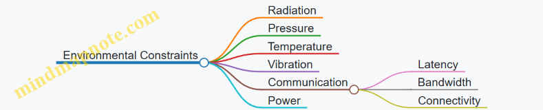
Example: In a satellite OS, radiation-hardened memory management is critical to prevent bit flips caused by cosmic rays.
Prioritize Reliability and Fault Tolerance
- Implement watchdog timers and heartbeat monitoring
- Design for redundancy in critical components
- Use checkpointing and rollback mechanisms
- Include self-healing and recovery strategies
Example: NASA’s RTEMS OS uses watchdog timers to reset unresponsive subsystems during satellite operations.
Ensure Real-Time Performance
- Choose appropriate scheduling algorithms (priority-based, preemptive)
- Minimize interrupt latency and jitter
- Guarantee deterministic response times
Example: FreeRTOS deployed in underwater autonomous vehicles uses priority-based scheduling to ensure sensor data is processed within strict deadlines.
Optimize Memory and Resource Management
- Use static memory allocation where possible
- Implement memory protection and isolation
- Manage limited resources efficiently
Example: Defense embedded OSes often use Memory Protection Units (MPUs) to isolate critical processes and prevent faults from cascading.
Design for Security and Safety
- Incorporate secure boot and trusted execution environments
- Harden OS against cyber and physical attacks
- Follow relevant certification standards (e.g., MILS, DO-178C)
Example: MILS architecture is implemented to enforce strict separation of security domains in defense systems.
Facilitate Robust Communication
- Use protocols tolerant to high latency and low bandwidth
- Implement encryption and authentication
- Design for intermittent connectivity
Example: Delay-Tolerant Networking (DTN) protocols enable data transmission between deep-sea sensors and surface stations despite intermittent links.
Implement Power Management Strategies
- Employ dynamic voltage and frequency scaling (DVFS)
- Use sleep modes and wake-up triggers
- Schedule tasks with energy efficiency in mind
Example: Satellite onboard computers dynamically reduce CPU frequency during idle periods to conserve power.
Adopt Modular and Scalable Design
- Structure OS components for easy updates and extensions
- Separate critical and non-critical modules
- Support scalability for different mission sizes
Example: RTEMS allows modular kernel configurations tailored to specific spacecraft mission requirements.
Conduct Rigorous Testing and Validation
- Use simulation environments replicating extreme conditions
- Perform field testing under real operational scenarios
- Automate regression and stress testing
Example: Autonomous underwater vehicle OSes undergo pressure chamber testing to validate system behavior under deep-sea conditions.
Maintain Comprehensive Documentation and Traceability
- Document design decisions, configurations, and test results
- Ensure traceability for certification and maintenance
Example: Defense contractors maintain detailed traceability matrices linking requirements to implementation and tests to satisfy certification audits.
Summary Mind Map
This checklist serves as a practical guide to ensure that operating systems developed for extreme environments meet the stringent demands of reliability, security, and performance. Integrating these considerations early and throughout the development lifecycle significantly increases mission success and system longevity.
13.3 Common Pitfalls and How to Avoid Them
Operating systems designed for extreme environments such as space, deep sea, and defense face unique challenges. Recognizing common pitfalls early in the development process can save time, resources, and mission success. Below, we explore frequent mistakes and practical strategies to avoid them, supported by mind maps and real-world examples.
Pitfall 1: Underestimating Environmental Impact on System Reliability
Extreme environments impose harsh physical conditions—radiation in space, high pressure underwater, or electromagnetic interference in defense systems—that can degrade hardware and software reliability.
How to Avoid:
- Incorporate radiation-hardened components and error-correcting codes.
- Use fault-tolerant OS designs with redundancy and watchdog timers.
- Perform environment-specific stress testing.
Example: NASA’s RTEMS OS integrates watchdog timers and triple modular redundancy (TMR) to mitigate radiation-induced faults in satellites.
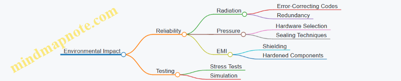
Pitfall 2: Ignoring Real-Time Constraints
Failing to meet strict timing requirements can cause mission-critical failures, especially in defense and space applications where deterministic behavior is essential.
How to Avoid:
- Use RTOS with proven deterministic scheduling algorithms.
- Prioritize tasks correctly and implement priority inheritance to avoid priority inversion.
- Profile and analyze worst-case execution times (WCET).
Example: Implementing priority-based preemptive scheduling in FreeRTOS for an underwater vehicle’s sensor data processing ensures timely responses.
Pitfall 3: Overlooking Power Management
Extreme environment systems often operate on limited power sources. Neglecting energy efficiency leads to shortened mission duration and system failures.
How to Avoid:
- Implement dynamic voltage and frequency scaling (DVFS).
- Use energy-aware scheduling algorithms.
- Design sleep and wake-up modes tailored to mission profiles.
Example: A deep-sea autonomous vehicle running Linux-based embedded OS employs energy-efficient scheduling to maximize battery life during long missions.
Pitfall 4: Insufficient Security Measures
Defense systems are prime targets for cyber and physical attacks. Inadequate security can compromise mission integrity.
How to Avoid:
- Integrate secure boot and trusted execution environments (TEE).
- Employ MILS architecture for multi-level security.
- Regularly update and patch OS components.
Example: MILS architecture implementation in a defense drone OS ensures compartmentalization and limits attack surfaces.
Pitfall 5: Poor Testing and Validation
Skipping comprehensive testing leads to undetected bugs and system failures in the field.
How to Avoid:
- Use simulation environments mimicking extreme conditions.
- Conduct field testing under real operational scenarios.
- Automate regression testing and continuous integration.
Example: Continuous integration pipelines with hardware-in-the-loop simulation validate OS updates for space probes.
Pitfall 6: Neglecting Modularity and Scalability
Monolithic designs hinder adaptability and maintenance, especially when mission requirements evolve.
How to Avoid:
- Design modular OS components with clear interfaces.
- Use scalable architectures to accommodate hardware upgrades.
- Document APIs and maintain version control.
Example: Modular microkernel OS architectures allow swapping communication modules without affecting core system in defense applications.
Summary Table of Common Pitfalls and Avoidance Strategies
| Pitfall | Avoidance Strategy | Example Application |
|---|---|---|
| Environmental Impact | Fault tolerance, redundancy, stress testing | NASA RTEMS with watchdog timers |
| Ignoring Real-Time Constraints | RTOS with deterministic scheduling, WCET profiling | FreeRTOS in underwater vehicles |
| Overlooking Power Management | DVFS, energy-aware scheduling, sleep modes | Linux-based embedded OS in deep-sea vehicles |
| Insufficient Security Measures | Secure boot, MILS, patch management | Defense drone OS with MILS architecture |
| Poor Testing and Validation | Simulation, field testing, automated CI | Hardware-in-the-loop for space probes |
| Neglecting Modularity & Scalability | Modular microkernel design, documentation | Modular OS for defense communication systems |
By proactively addressing these pitfalls with the recommended best practices and examples, systems programmers and embedded engineers can significantly enhance the robustness, reliability, and security of operating systems tailored for extreme environments.
13.4 Final Example: End-to-End OS Design for a Multi-Environment Mission
Designing an operating system (OS) that can seamlessly operate across multiple extreme environments—space, deep sea, and defense—requires a holistic approach that integrates best practices from each domain. This section walks through a comprehensive example of an end-to-end OS design tailored for a multi-environment mission, illustrating key design decisions, architecture, and implementation strategies.
Mission Context
Imagine a mission involving an autonomous exploration vehicle capable of operating in space, transitioning to deep sea environments, and supporting defense-related surveillance tasks. The OS must handle diverse challenges such as radiation in space, high pressure underwater, and stringent security requirements in defense scenarios.
Step 1: Requirements Gathering and Analysis
- Reliability & Fault Tolerance: Critical in all environments to ensure mission success.
- Real-Time Performance: Required for navigation, sensor data processing, and control.
- Security: Especially vital for defense operations.
- Power Efficiency: Essential for long-duration missions with limited energy sources.
- Modularity & Scalability: To adapt OS components based on environment.
Step 2: Architectural Design
Mind Map: OS Architectural Design for Multi-Environment Mission
Step 3: Kernel Selection and Customization
Choice: Microkernel-based RTOS (e.g., a customized version of RTEMS or seL4)
Reasoning: Microkernel offers fault isolation, modularity, and security advantages crucial for multi-environment adaptability.
Example: Implementing a minimal microkernel with IPC optimized for high-latency space communication and underwater sensor data aggregation.
Step 4: Environment-Specific Modules
Mind Map: Environment-Specific OS Modules
Example:
- Space Module uses triple modular redundancy (TMR) for critical sensor readings.
- Deep Sea Module implements energy-aware scheduling to maximize battery life.
- Defense Module integrates a secure bootloader with cryptographic verification.
Step 5: Scheduling and Real-Time Guarantees
Implementation: Priority-based preemptive scheduler with support for priority inheritance to avoid priority inversion.
Code Snippet (Pseudocode):
void schedule() {
  Task *next = highest_priority_ready_task();
  if (current_task->priority < next->priority) {
    preempt(current_task, next);
  }
}

void preempt(Task *current, Task *next) {
  save_context(current);
  load_context(next);
  current_task = next;
}
Example: In deep sea mode, sensor data acquisition tasks have highest priority to ensure timely processing.
Step 6: Fault Tolerance and Recovery
- Watchdog Timer: Monitors system health and triggers reset if OS hangs.
- Checkpointing: Periodic state saving to enable rollback on failure.
- Redundancy: Critical components duplicated with voting mechanisms.
Example: In space mode, watchdog timer resets the navigation subsystem if no heartbeat is received within 2 seconds.
Step 7: Communication Protocols
- Space: Delay-Tolerant Networking (DTN) to handle long latency.
- Deep Sea: Acoustic modem protocols optimized for low bandwidth.
- Defense: Encrypted and authenticated communication channels.
Example: Implementing a DTN bundle protocol layer that queues messages during communication blackouts.
Step 8: Power Management
- Integrate DVFS to reduce power consumption during idle periods.
- Use sleep modes aggressively when sensors are inactive.
Example: Deep sea module puts non-critical tasks to sleep during long transit phases, waking only for periodic health checks.
Step 9: Security Measures
- Secure boot process verifies OS integrity on startup.
- Trusted Execution Environment (TEE) isolates sensitive operations.
- Role-based access control for defense modules.
Example: Defense module uses ARM TrustZone to isolate cryptographic key management.
Step 10: Health Monitoring and Predictive Maintenance
- Continuous monitoring of CPU load, memory usage, sensor status.
- Predictive algorithms analyze trends to preempt failures.
Example: Health monitoring subsystem triggers alerts if memory leaks are detected, allowing preemptive reboot.
Summary Mind Map
Mind Map: End-to-End OS Design Summary
This example demonstrates how integrating best practices and tailored modules within a modular microkernel OS architecture can address the diverse challenges of operating systems in extreme environments. By carefully balancing real-time requirements, fault tolerance, security, and power management, systems programmers and embedded engineers can build robust OS platforms capable of supporting complex multi-environment missions.
13.5 Resources and Further Reading for Systems Programmers and Engineers
To deepen your understanding and enhance your skills in developing operating systems for extreme environments such as space, deep sea, and defense, this section provides a curated list of resources, including books, research papers, online courses, tools, and communities. Additionally, mind maps are included to visually organize key topics and guide your learning journey.
Recommended Books
-
“Real-Time Systems” by Jane W. S. Liu
- Comprehensive coverage of real-time operating system principles and scheduling algorithms.
-
“Embedded Systems Architecture: A Comprehensive Guide for Engineers and Programmers” by Tammy Noergaard
- Practical insights into embedded OS design and hardware-software integration.
-
“Operating Systems: Three Easy Pieces” by Remzi H. Arpaci-Dusseau and Andrea C. Arpaci-Dusseau
- Foundational concepts of OS with clear explanations and examples.
-
“Fault-Tolerant Systems” by Israel Koren and C. Mani Krishna
- Detailed exploration of fault tolerance techniques applicable in extreme environments.
-
“Spacecraft Systems Engineering” by Peter Fortescue, Graham Swinerd, and John Stark
- Covers system design including software and OS considerations for space missions.
Influential Research Papers
-
“RTEMS: Real-Time Executive for Multiprocessor Systems”
- Overview and case studies of RTEMS in space applications.
-
“Delay-Tolerant Networking Architecture” by Kevin Fall
- Foundational paper on networking in high-latency environments like space.
-
“Energy-Efficient Scheduling for Embedded Systems” by Y. Zhang et al.
- Techniques for power management in embedded OS.
-
“MILS: A High-Assurance Security Architecture” by John Rushby
- Discusses Multiple Independent Levels of Security for defense systems.
Online Courses and Tutorials
-
Embedded Systems - Shape The World: Microcontroller Input/Output (edX, University of Texas at Austin)
- Hands-on embedded programming fundamentals.
-
Real-Time Operating Systems Concepts and Implementation (Udemy)
- Covers RTOS basics with practical examples.
-
NASA’s Open Source Software Catalog
- Access to space-grade OS projects and documentation.
-
Linux Foundation’s Embedded Linux Development (edX)
- Deep dive into Linux for embedded systems.
Tools and Development Environments
-
QEMU
- Emulator for testing OS in various hardware configurations.
-
FreeRTOS
- Popular open-source RTOS with extensive documentation and examples.
-
RTEMS
- Real-time OS widely used in aerospace and defense.
-
Valgrind
- Debugging and profiling tool for memory and threading issues.
-
JTAG Debuggers
- Essential hardware debugging tools for embedded systems.
Communities and Forums
-
Stack Overflow Embedded Systems Tag
- Active Q&A platform for embedded and OS programming.
-
RTEMS Mailing Lists and Forums
- Community support for RTEMS developers.
-
EmbeddedRelated.com
- Articles, blogs, and forums focused on embedded systems.
-
Defense and Aerospace Software Engineering Groups on LinkedIn
- Networking and knowledge sharing with industry professionals.
Mind Maps
Mind Map 1: Core Topics in Extreme Environment Operating Systems
Mind Map 2: Real-Time Operating Systems (RTOS) Essentials
Mind Map 3: Security and Certification in Defense OS
Practical Example: Using RTEMS in Space Systems
#include <rtems.h>
#include <stdio.h>

rtems_task Init(rtems_task_argument argument) {
  printf("RTEMS Space OS Example: Task Started\n");
  while(1) {
    // Simulate sensor data processing
    rtems_task_wake_after(RTEMS_MILLISECONDS_TO_TICKS(1000));
    printf("Processing sensor data...\n");
  }
}

rtems_task Init_task(rtems_task_argument argument) {
  rtems_task_create(
    rtems_build_name('I','N','I','T'),
    1, RTEMS_MINIMUM_STACK_SIZE, RTEMS_DEFAULT_MODES, RTEMS_DEFAULT_ATTRIBUTES, &Init
  );
  rtems_task_start(Init, 0);
}

RTEMS_INITIAL_TASKS_TABLE(
  {
    {Init_task, 1, RTEMS_MINIMUM_STACK_SIZE * 2, RTEMS_DEFAULT_MODES, RTEMS_DEFAULT_ATTRIBUTES, NULL}
  }
);
This simple RTEMS example demonstrates a periodic task simulating sensor data processing in a space environment, emphasizing real-time scheduling and task management.
Summary
This resource collection and the accompanying mind maps provide a structured pathway for systems programmers, embedded engineers, and defense contractors to master operating systems tailored for extreme environments. Leveraging these materials will help you design, implement, and maintain robust, secure, and efficient OS solutions capable of thriving under the most demanding conditions.