Industrial Robotics: Precision Motion & Sensors
1. Introduction to Industrial Robotics and Precision Motion
1.1 Overview of Industrial Robotics: Definitions and Applications
Industrial robotics is a branch of engineering and technology that deals with the design, construction, operation, and use of robots in industrial environments. These robots are automated machines capable of performing complex tasks with high precision, speed, and repeatability, often replacing or assisting human labor in manufacturing and production processes.
Definition of Industrial Robotics
-
Industrial Robot: A programmable, multifunctional manipulator designed to move materials, parts, tools, or specialized devices through variable programmed motions for the performance of a variety of tasks.
-
Key Characteristics:
- Programmability
- Reprogrammability
- Multipurpose use
- Automation capability
Applications of Industrial Robotics
Industrial robots are widely used across various sectors to improve productivity, quality, and safety. Common applications include:
- Material Handling: Loading/unloading, palletizing, packaging
- Welding: Spot welding, arc welding
- Assembly: Electronics, automotive parts
- Painting and Coating: Automotive bodies, consumer products
- Machine Tending: Operating CNC machines, presses
- Inspection and Quality Control: Vision-guided inspection
Mind Map: Industrial Robotics Overview
Example 1: Automotive Manufacturing
In automotive plants, industrial robots perform spot welding with extreme precision and speed. Robots handle repetitive welding tasks on car frames, ensuring consistent quality and reducing human exposure to hazardous environments.
Example 2: Electronics Assembly
Robots equipped with precision motion systems assemble small electronic components on circuit boards. Their accuracy minimizes defects and increases throughput in high-volume production.
Mind Map: Benefits and Challenges
Best Practice Highlight
Selecting the Right Robot for Your Application:
- Analyze task requirements (payload, reach, precision)
- Consider environment (cleanroom, hazardous areas)
- Evaluate flexibility needs (single-task vs multi-task robots)
Summary
Industrial robotics transforms manufacturing by automating complex, repetitive, or hazardous tasks. Understanding their definitions and applications lays the foundation for leveraging precision motion and sensor technologies effectively.
1.2 Importance of Precision Motion in Robotics
Precision motion is a cornerstone of industrial robotics, enabling robots to perform tasks with high accuracy, repeatability, and reliability. Without precise motion control, robots would fail to meet the stringent demands of modern manufacturing, leading to defects, inefficiencies, and increased costs.
Why Precision Motion Matters
- Accuracy: Ensures the robot reaches the exact position required for the task.
- Repeatability: Guarantees consistent performance over multiple cycles.
- Efficiency: Reduces cycle times by minimizing corrections and adjustments.
- Quality: Improves product quality by maintaining tight tolerances.
- Safety: Prevents collisions and errors that could damage equipment or harm operators.
Mind Map: Key Benefits of Precision Motion
Real-World Example: Automotive Assembly
In automotive manufacturing, robotic arms perform tasks such as welding, painting, and assembly. Precision motion ensures that welds are placed exactly where needed, paint is applied evenly, and parts fit together perfectly. For instance, a robotic spot welder must position its electrode within fractions of a millimeter to create strong, defect-free welds. Any deviation can lead to weak joints or rework.
Mind Map: Precision Motion in Automotive Robotics
Example: Pick-and-Place Robots in Electronics
Pick-and-place robots in electronics manufacturing handle tiny components like microchips and resistors. Precision motion allows these robots to pick components from feeders and place them on circuit boards with micron-level accuracy. This precision reduces errors, improves throughput, and minimizes material waste.
Mind Map: Precision Motion in Electronics Pick-and-Place
Best Practice: Calibrating Motion Systems
Regular calibration of robotic motion systems is essential to maintain precision. For example, using laser interferometers to verify linear axis accuracy or employing encoder feedback to correct positioning errors ensures the robot continues to perform within specified tolerances.
Summary
Precision motion is vital in industrial robotics to achieve the high standards required in modern manufacturing. It directly impacts product quality, operational efficiency, and workplace safety. Understanding and implementing precision motion best practices enable engineers and technicians to optimize robotic performance across diverse applications.
1.3 Key Components of Precision Motion Systems
Precision motion systems are the backbone of industrial robotics, enabling robots to perform tasks with high accuracy, repeatability, and speed. Understanding the key components involved helps engineers and technicians design, troubleshoot, and optimize robotic systems effectively.
Mind Map: Key Components of Precision Motion Systems
Actuators
Actuators convert electrical signals into mechanical motion. They are fundamental for achieving precise movement.
-
Servo Motors: Provide closed-loop control with feedback, enabling precise positioning and speed control.
- Example: A robotic arm in an automotive assembly line uses servo motors to position welding tools with sub-millimeter accuracy.
-
Stepper Motors: Operate in open-loop mode with discrete steps, suitable for applications requiring moderate precision.
- Example: Pick-and-place machines in electronics manufacturing often use stepper motors for repetitive positioning.
-
Linear Actuators: Convert rotary motion into linear motion, often used for precise linear displacement.
- Example: CNC machines use ball screw-driven linear actuators to move cutting tools along axes.
Transmission Elements
These components transfer motion from actuators to the robot’s moving parts, influencing precision and backlash.
-
Gears: Provide torque multiplication and speed reduction but can introduce backlash if not properly designed.
- Example: Harmonic drive gears are used in precision robotics due to their near-zero backlash.
-
Belts and Pulleys: Lightweight and flexible but may introduce elasticity affecting precision.
- Example: Conveyor robots use timing belts for smooth linear motion.
-
Ball Screws: Convert rotary motion to linear with high efficiency and minimal backlash.
- Example: Precision CNC milling machines rely on ball screws for accurate tool positioning.
-
Rack and Pinion: Used for linear motion over longer distances.
- Example: Automated guided vehicles (AGVs) use rack and pinion systems for steering.
Sensors
Sensors provide critical feedback to the control system, enabling closed-loop precision.
-
Position Sensors: Measure the exact position of moving parts.
- Example: Optical encoders on robotic joints provide position feedback for precise articulation.
-
Velocity Sensors: Measure speed to regulate motion dynamics.
- Example: Tachometers integrated with motors help maintain consistent speed during pick-and-place operations.
-
Force/Torque Sensors: Detect applied forces, essential for delicate assembly tasks.
- Example: Force sensors in robotic grippers prevent damage to fragile components.
Controllers
Controllers process sensor data and command actuators to achieve desired motion.
-
Motion Controllers: Specialized devices that execute complex motion profiles.
- Example: A motion controller orchestrates multi-axis movements in a robotic welding cell.
-
PLCs: Programmable devices that manage overall automation including motion control.
- Example: PLCs coordinate conveyor speed with robotic arm cycles in packaging lines.
Feedback Systems
Feedback systems close the control loop, ensuring accuracy and repeatability.
-
Encoders: Provide digital signals representing position or speed.
- Example: Incremental encoders track the rotation of robotic joints.
-
Resolvers: Analog devices that provide robust position feedback in harsh environments.
- Example: Aerospace robots use resolvers for reliable feedback under vibration.
Mechanical Structures
Mechanical components support and guide motion while minimizing friction and wear.
-
Bearings: Reduce friction between moving parts.
- Example: Cross-roller bearings in robotic wrists enable smooth rotation with high precision.
-
Guides and Rails: Provide linear guidance.
- Example: Linear guide rails in semiconductor manufacturing robots ensure smooth, precise motion.
Power Supply
Power electronics convert and regulate energy for actuators.
-
Drives: Control motor current and voltage.
- Example: Servo drives regulate current to servo motors for precise torque control.
-
Amplifiers: Boost control signals to drive actuators.
- Example: Amplifiers in high-power robots ensure sufficient torque for heavy payloads.
Integrated Example: Precision Motion System in a Robotic Assembly Cell
Consider a robotic assembly cell assembling smartphone components:
- Actuators: Servo motors drive the robotic arms.
- Transmission: Harmonic drives minimize backlash.
- Sensors: Optical encoders provide joint position feedback; force sensors monitor grip pressure.
- Controller: A motion controller executes precise multi-axis trajectories.
- Feedback: Encoders and force sensors close the control loop.
- Mechanical: Linear guides ensure smooth arm extension.
- Power: Servo drives regulate motor performance.
This integrated system ensures components are placed with micron-level accuracy, reducing defects and increasing throughput.
Understanding these components and their interplay is essential for designing and maintaining high-performance precision motion systems in industrial robotics.
1.4 Best Practices: Selecting the Right Robot for Precision Tasks with Real-World Examples
Selecting the right industrial robot for precision tasks is critical to achieving high accuracy, repeatability, and efficiency in manufacturing and automation processes. This section outlines best practices for choosing the appropriate robot, supported by real-world examples and mind maps to clarify the decision-making process.
Key Factors to Consider When Selecting a Robot for Precision Tasks
- Task Requirements: Define the precision level, payload, reach, speed, and environment.
- Robot Type: Cartesian, SCARA, 6-axis articulated, delta robots, etc.
- Repeatability & Accuracy: Understand the robot’s specifications and how they align with task needs.
- Payload Capacity: Ensure the robot can handle the weight of tools and parts without sacrificing precision.
- Environmental Conditions: Consider temperature, dust, vibration, and other factors affecting performance.
- Integration Capability: Compatibility with sensors, vision systems, and control architecture.
- Cost and ROI: Balance between upfront investment and long-term benefits.
Mind Map: Selecting the Right Robot for Precision Tasks
Best Practice 1: Define Clear Precision and Task Requirements
Before selecting a robot, clearly define the precision requirements. For example, micro-assembly tasks may require repeatability within ±0.01 mm, whereas palletizing may tolerate ±1 mm.
Example: A manufacturer of precision optical lenses requires a robot with sub-micron positioning accuracy to handle delicate lens components without damage. They specified a 6-axis articulated robot with high-resolution encoders and integrated force sensors to maintain gentle handling.
Best Practice 2: Choose the Robot Type Based on Task Geometry and Speed
- Cartesian Robots excel in linear, high-precision tasks with straightforward paths.
- SCARA Robots are ideal for fast, precise horizontal movements, such as assembly.
- 6-Axis Articulated Robots offer flexibility for complex 3D tasks.
- Delta Robots are suited for high-speed pick-and-place with moderate precision.
Example: An electronics manufacturer uses SCARA robots for PCB assembly due to their fast, precise horizontal reach, enabling cycle times under 3 seconds per unit.
Mind Map: Robot Type Selection Based on Task
Best Practice 3: Evaluate Repeatability and Accuracy Specifications
Check the robot’s datasheet for repeatability (the robot’s ability to return to a position) and absolute accuracy. For precision tasks, repeatability is often more critical.
Example: A semiconductor wafer handling robot requires ±0.005 mm repeatability. The company selected a robot with direct-drive motors and high-resolution encoders to meet this stringent requirement.
Best Practice 4: Consider Payload and Tooling Weight
The robot must maintain precision under load. Overloading can reduce accuracy and increase wear.
Example: In a pharmaceutical packaging line, a robot handles vials and a vision system camera mounted on the end-effector. The combined payload was carefully calculated to ensure the robot’s precision was not compromised.
Best Practice 5: Assess Environmental and Operational Conditions
Robots operating in harsh environments may need special enclosures or IP-rated designs.
Example: An automotive paint shop uses a 6-axis robot with IP67 rating to withstand paint overspray and humidity, ensuring consistent precision in spray patterns.
Best Practice 6: Integration with Sensors and Control Systems
Precision tasks often require sensor feedback (vision, force, position). Ensure the robot supports integration with these systems.
Example: A food packaging line integrates a vision system with a delta robot to detect and precisely place irregularly shaped items, improving accuracy and reducing waste.
Best Practice 7: Analyze Total Cost of Ownership and ROI
Consider not only the purchase price but also maintenance, downtime costs, and productivity improvements.
Example: A manufacturer chose a slightly more expensive robot with advanced diagnostics and predictive maintenance features, reducing downtime by 30% and improving overall throughput.
Summary
Selecting the right robot for precision tasks requires a holistic approach considering task requirements, robot type, performance specs, environment, integration, and cost. Using mind maps to visualize these factors helps engineers and technicians make informed decisions.
Additional Mind Map: Comprehensive Robot Selection Workflow
1.5 Case Study: Precision Motion in Automotive Assembly Lines
Industrial robotics has revolutionized automotive assembly lines by enabling high precision, repeatability, and efficiency. This case study explores how precision motion control is implemented in automotive manufacturing, highlighting best practices and real-world examples.
Overview
Automotive assembly lines involve complex tasks such as welding, painting, part placement, and inspection. Each task demands precise robotic motion to ensure quality and safety.
Key Areas of Precision Motion in Automotive Assembly
Mind Map: Precision Motion in Automotive Assembly
Example 1: Spot Welding with Precision Motion
Spot welding requires the robotic arm to position the welding gun with millimeter accuracy to join metal sheets without damaging surrounding areas.
- Best Practice: Use servo-driven multi-axis robotic arms with high-resolution encoders.
- Example: Toyota’s assembly line uses 6-axis robots with real-time position feedback to maintain ±0.1 mm accuracy during welding.
Mind Map: Spot Welding Precision
Example 2: Painting Robots Ensuring Uniform Coating
Painting robots must maintain consistent speed, distance, and spray angle to avoid defects such as runs or uneven coating.
- Best Practice: Integrate laser distance sensors and vision systems for dynamic adjustment.
- Example: BMW employs painting robots equipped with LIDAR sensors to continuously measure the distance to the car body, adjusting arm speed and spray parameters accordingly.
Mind Map: Painting Robot Precision
Example 3: Material Handling with Pick-and-Place Robots
Robots pick parts from conveyors and place them accurately on assembly fixtures.
- Best Practice: Use force-torque sensors and vision guidance to ensure precise grasp and placement.
- Example: Ford uses vision-guided robots with integrated force sensors to handle delicate components, reducing damage and improving cycle time.
Mind Map: Pick-and-Place Precision
Integration of Sensors and Motion Control
In automotive assembly, sensor data is fused with motion control algorithms to enhance precision.
- Real-time feedback loops correct deviations instantly.
- Multi-sensor fusion (e.g., combining encoders, force sensors, and vision) improves reliability.
Mind Map: Sensor-Motion Integration
Summary of Best Practices in Automotive Precision Motion
- Select high-precision servo motors with appropriate torque and speed.
- Employ multi-axis robotic arms for complex motion paths.
- Integrate diverse sensors (encoders, force, vision) for comprehensive feedback.
- Use real-time control systems with adaptive algorithms.
- Regularly calibrate sensors and actuators to maintain accuracy.
- Implement predictive maintenance using sensor data analytics.
Final Thoughts
Precision motion in automotive assembly lines is critical to product quality and operational efficiency. By combining advanced robotics, sensor technologies, and best practices in motion control, manufacturers achieve high throughput with minimal defects, setting industry standards for automation excellence.
2. Fundamentals of Precision Motion Control
2.1 Understanding Motion Control Principles
Motion control is the foundation of precision in industrial robotics, enabling robotic systems to move accurately, smoothly, and repeatably. This section explores the fundamental principles that govern motion control, breaking down complex concepts into understandable components with practical examples and mind maps.
What is Motion Control?
Motion control refers to the process of managing the position, velocity, and acceleration of mechanical systems. In robotics, it involves controlling actuators (motors) to achieve desired movements with high precision.
Key Elements of Motion Control
- Controller: The brain that processes commands and feedback to generate control signals.
- Actuator: The device (e.g., servo motor) that moves the robot.
- Feedback Device: Sensors (encoders, resolvers) that provide position or velocity data.
- Drive: The power electronics that supply current to the actuator.
Motion Control Loop
A typical motion control system operates in a closed-loop configuration:
Mind Map: Motion Control Loop
Types of Motion Control
- Open-Loop Control: Commands sent without feedback; simple but less accurate.
- Closed-Loop Control: Uses feedback to correct errors; essential for precision.
Control Strategies
- Position Control: Ensures the robot reaches and holds a target position.
- Velocity Control: Controls the speed of movement.
- Torque Control: Regulates the force applied.
PID Control: The Heart of Motion Control
Most industrial robots use PID (Proportional-Integral-Derivative) controllers to maintain precision.
Mind Map: PID Controller Components
Example:
A robotic arm must move its end-effector to a precise point. The PID controller continuously adjusts motor commands based on the difference between the desired and actual position, minimizing overshoot and steady-state error.
Example: Pick-and-Place Robot Motion Control
In a pick-and-place application, the robot must move quickly but stop precisely at the pick location:
- The controller receives the target coordinates.
- Servo motors actuate the joints.
- Encoders provide real-time position feedback.
- PID control adjusts motor inputs to reduce position error.
This ensures the robot picks the object without collision or misalignment.
Factors Affecting Motion Control Precision
- Mechanical backlash and compliance
- Sensor resolution and accuracy
- Controller tuning and algorithm choice
- Environmental disturbances (vibration, temperature)
Best Practices for Effective Motion Control
- Use closed-loop control with high-resolution feedback devices.
- Properly tune PID parameters for the specific application.
- Minimize mechanical play in the system.
- Regularly calibrate sensors and actuators.
Summary Mind Map: Understanding Motion Control Principles
Understanding these principles equips robotics engineers and automation technicians to design, implement, and troubleshoot precision motion systems effectively, ensuring high performance and reliability in industrial applications.
2.2 Types of Motion: Linear, Rotary, and Multi-Axis
Industrial robots rely on precise motion control to perform tasks efficiently and accurately. Understanding the fundamental types of motion is essential for robotics engineers, automation technicians, and manufacturing leads to design, program, and maintain robotic systems effectively.
Linear Motion
Linear motion refers to movement along a straight path in one dimension. It is the simplest form of motion and is widely used in applications requiring precise positioning along a single axis.
Characteristics:
- Movement along X, Y, or Z axis
- Controlled by linear actuators such as ball screws, linear motors, or pneumatic cylinders
- High repeatability and accuracy
Examples:
- Pick-and-place robots moving components from one conveyor belt to another
- CNC machines moving the cutting tool along a straight path
Best Practice:
Use high-precision linear guides and feedback sensors like linear encoders to ensure accurate positioning and reduce backlash.
Mind Map: Linear Motion
Rotary Motion
Rotary motion involves movement around a fixed axis or pivot point. It is fundamental in robotic joints and mechanisms that require rotational positioning.
Characteristics:
- Movement in degrees or radians around an axis
- Controlled by servo motors, stepper motors, or rotary actuators
- Can be continuous or limited rotation
Examples:
- Robotic arm joints rotating to position tools
- Turntables rotating parts for assembly
Best Practice:
Implement high-resolution rotary encoders and apply proper tuning of servo parameters to minimize overshoot and oscillations.
Mind Map: Rotary Motion
Multi-Axis Motion
Multi-axis motion combines linear and rotary movements across multiple degrees of freedom, enabling complex, precise positioning and orientation.
Characteristics:
- Simultaneous control of multiple axes (e.g., 3, 5, 6 axes)
- Enables complex trajectories and orientations
- Requires advanced motion controllers and sensor fusion
Examples:
- 6-axis articulated robotic arms used in welding, painting, and assembly
- SCARA robots combining rotary and linear axes for fast pick-and-place
Best Practice:
Use synchronized multi-axis controllers with integrated sensor feedback (encoders, force sensors, vision systems) to ensure smooth coordinated motion and avoid collisions.
Mind Map: Multi-Axis Motion
Integrated Example: Robotic Welding Cell
A robotic welding cell typically uses multi-axis articulated robots (6-axis) to position the welding torch precisely. The base and shoulder joints provide rotary motion, while the arm extends linearly. Position sensors and encoders ensure the torch follows the programmed path with high precision. Force sensors monitor contact pressure, and vision systems verify weld quality.
Summary
| Motion Type | Description | Actuators | Sensors | Typical Applications |
|---|---|---|---|---|
| Linear | Movement along a straight line | Ball screws, linear motors | Linear encoders, LVDTs | Pick-and-place, CNC machining |
| Rotary | Rotation around an axis | Servo motors, steppers | Rotary encoders | Robotic joints, turntables |
| Multi-Axis | Combined linear & rotary motion | Multi-axis servo systems | Sensor fusion (encoders, vision, force) | Articulated arms, SCARA robots |
Understanding these motion types and their integration with sensors is critical for designing precise and efficient industrial robotic systems.
2.3 Actuators and Drives: Servo Motors, Stepper Motors, and Linear Actuators
Industrial robotics relies heavily on precise and reliable actuators and drives to execute controlled motion. This section explores the key types of actuators used in precision motion systems: servo motors, stepper motors, and linear actuators. We will discuss their working principles, advantages, limitations, and practical examples to help robotics engineers, automation technicians, and manufacturing leads select and implement the right actuator for their applications.
Overview Mind Map: Types of Actuators in Industrial Robotics
Servo Motors
Working Principle: Servo motors are rotary actuators that provide precise control of angular position, velocity, and acceleration. They operate with a closed-loop feedback system, typically using encoders or resolvers to continuously monitor position and adjust accordingly.
Key Features:
- High torque-to-inertia ratio
- Smooth and continuous rotation
- Closed-loop control for accuracy
- High dynamic response
Best Practices:
- Use servo motors when applications require high precision and smooth motion, such as robotic arms and CNC machines.
- Ensure proper tuning of PID controllers to optimize performance and reduce overshoot.
- Select servo motors with appropriate torque ratings and speed capabilities for the load.
Example: In an automotive assembly line, a robotic arm equipped with servo motors precisely positions car body panels for welding. The closed-loop feedback ensures the arm moves smoothly and accurately to the exact coordinates, minimizing errors and rework.
Stepper Motors
Working Principle: Stepper motors are brushless DC motors that move in discrete steps, allowing open-loop control of position without requiring feedback sensors. Each input pulse moves the motor shaft by a fixed angle.
Key Features:
- Simple control without feedback (open-loop)
- High holding torque at standstill
- Precise incremental movement
- Cost-effective for moderate precision tasks
Best Practices:
- Ideal for applications where cost is a concern and moderate precision suffices, such as conveyor indexing or simple pick-and-place systems.
- Use microstepping drivers to increase resolution and reduce vibration.
- Implement stall detection or add encoders if the application demands higher reliability.
Example: A packaging robot uses stepper motors to index trays on a conveyor belt. The motor moves in fixed increments to align trays for filling, providing reliable positioning without the complexity of feedback systems.
Linear Actuators
Working Principle: Linear actuators convert rotary motion into linear displacement. Electric linear actuators typically use lead screws, ball screws, or belt drives driven by motors (servo or stepper) to achieve precise linear positioning.
Key Features:
- Direct linear motion control
- High force output with ball screw designs
- Compact and easy to integrate
- Can be combined with servo or stepper motors for feedback control
Best Practices:
- Choose electric linear actuators for applications requiring clean, precise, and repeatable linear movement, such as pick-and-place or material handling.
- Match actuator stroke length and load capacity to the application.
- Regularly maintain and lubricate mechanical components to ensure longevity and accuracy.
Example: In an electronics manufacturing line, a linear actuator precisely moves a soldering head along the X-axis to apply solder paste on circuit boards. The actuator’s repeatable linear motion ensures consistent solder application.
Mind Map: Actuator Selection Criteria
Integrated Example: Robotic Pick-and-Place System
A robotic pick-and-place system in a pharmaceutical packaging line uses a combination of actuators:
- Servo Motors control the multi-axis robotic arm for smooth, precise positioning of delicate vials.
- Stepper Motors drive the indexing conveyor belts, providing cost-effective incremental movement.
- Linear Actuators handle vertical lifting and lowering of the gripper mechanism with repeatable accuracy.
This integration ensures high throughput, precision, and reliability while optimizing costs.
Summary
Understanding the characteristics and best practices of servo motors, stepper motors, and linear actuators empowers robotics professionals to design and maintain precision motion systems effectively. Selecting the right actuator based on application requirements, control complexity, and budget leads to improved performance and operational efficiency.
2.4 Best Practices: Tuning Servo Systems for Optimal Precision with Practical Examples
Achieving optimal precision in servo systems is critical for industrial robotics applications where accuracy, repeatability, and smooth motion are paramount. Proper tuning of servo systems ensures that the robotic arm or actuator performs its tasks with minimal error, reduced overshoot, and stable response.
Key Objectives of Servo Tuning
- Minimize position error
- Reduce overshoot and oscillations
- Achieve fast settling time
- Maintain system stability
Mind Map: Servo System Tuning Process
Step-by-Step Best Practices for Tuning Servo Systems
Understand Your System Dynamics
Before tuning, gather information about the mechanical load, inertia, friction, and any external disturbances. For example, a robotic arm handling lightweight objects will have different dynamics than one moving heavy parts.
Set Initial Controller Gains
- Proportional Gain (P): Controls the response speed. Too high causes oscillations; too low leads to sluggish response.
- Integral Gain (I): Eliminates steady-state error but can cause overshoot if too high.
- Derivative Gain (D): Dampens oscillations and improves stability.
Start with conservative values to avoid instability.
Use a Tuning Method
- Manual Tuning: Adjust gains incrementally while observing system response.
- Ziegler-Nichols Method: Increase P gain until oscillation occurs, then calculate I and D gains based on oscillation period.
- Auto-Tuning Software: Many servo drives offer built-in auto-tuning features that analyze system response and set optimal gains.
Test with Step Inputs
Apply step commands and observe:
- Rise time
- Overshoot
- Settling time
- Steady-state error
Adjust gains to minimize overshoot and settling time while maintaining stability.
Implement Feedforward Control
Feedforward control anticipates the required control effort based on desired motion, improving response and reducing error.
Validate Under Real Load Conditions
Test the tuned system with actual payloads and operating conditions to ensure robustness.
Practical Examples
Example 1: Tuning a Pick-and-Place Robot’s Servo
- Scenario: The robot arm exhibits overshoot when moving to pick positions.
- Action: Reduce proportional gain slightly and increase derivative gain to add damping.
- Result: Overshoot reduced by 40%, and settling time improved.
Example 2: Auto-Tuning a CNC Machine’s Servo Motors
- Scenario: Manual tuning was time-consuming and inconsistent.
- Action: Use the servo drive’s auto-tune feature.
- Result: Achieved optimal gains quickly, improving machining precision and reducing vibration.
Example 3: Feedforward Control in Conveyor Belt Positioning
- Scenario: Positioning errors occur due to variable load on the belt.
- Action: Implement feedforward control based on load estimation.
- Result: Position accuracy improved by 25%, and response time decreased.
Mind Map: Common Servo Tuning Challenges and Solutions
Summary
Tuning servo systems for optimal precision requires a balance between responsiveness and stability. By understanding system dynamics, carefully adjusting PID gains, leveraging auto-tuning tools, and validating under real conditions, engineers can achieve high precision in industrial robotics applications.
Incorporating feedforward control and adaptive strategies further enhances performance, especially in variable load environments.
Additional Resources
- Manufacturer servo tuning guides
- Simulation tools for PID tuning
- Case studies on servo tuning in industrial robots
2.5 Example: Precision Motion Control in Pick-and-Place Robots
Pick-and-place robots are widely used in manufacturing and assembly lines to move components from one location to another with high speed and precision. Achieving precision motion control in these robots is critical to ensure accuracy, repeatability, and efficiency.
Understanding the Pick-and-Place Robot Motion Control
Pick-and-Place Robot Motion Control Mind Map
Key Components and Their Roles
- Servo Motors: Provide precise control of angular or linear position, velocity, and acceleration.
- Encoders: Measure the position and speed of the robot’s joints to provide feedback for closed-loop control.
- Proximity Sensors: Detect the presence and position of objects to ensure correct pick-up.
- Control Algorithms: PID controllers and trajectory planners ensure smooth and accurate movements.
Best Practice: Implementing PID Control for Smooth and Accurate Motion
- Example: Tuning PID parameters to reduce overshoot and steady-state error.
- Start with conservative gains to avoid oscillations.
- Gradually increase proportional gain to improve response speed.
- Adjust integral gain to eliminate steady-state error.
- Fine-tune derivative gain to dampen oscillations.
Practical Example: Pick-and-Place Robot in Electronics Assembly
- Scenario: A robot picks small electronic components from a conveyor and places them on a PCB.
- Challenges: High precision required to avoid misplacement; components are small and delicate.
Implementation:
- Use high-resolution encoders on each joint for accurate position feedback.
- Employ vision sensors to verify component orientation and position.
- Apply PID control with feedforward terms to anticipate motion dynamics.
- Calibrate the robot workspace to align the robot coordinate system with the conveyor and PCB.
Outcome:
- Achieved placement accuracy within ±0.1 mm.
- Reduced cycle time by 15% due to optimized motion trajectories.
- Minimized component damage through gentle acceleration and deceleration profiles.
Mind Map: Example Workflow of Precision Motion Control in Pick-and-Place
Additional Example: Stepper Motor vs Servo Motor in Pick-and-Place
| Feature | Stepper Motor | Servo Motor |
|---|---|---|
| Precision | Moderate (open-loop) | High (closed-loop with encoder) |
| Control Complexity | Simple | Complex (requires feedback control) |
| Cost | Lower | Higher |
| Typical Use Case | Low-cost pick-and-place with moderate precision | High-speed, high-precision pick-and-place |
Best Practice: For applications requiring high precision and speed, servo motors with encoder feedback are preferred.
Summary
Precision motion control in pick-and-place robots hinges on the integration of accurate sensors, reliable actuators, and robust control algorithms. By carefully tuning control parameters and calibrating the system, manufacturers can achieve high throughput with minimal errors, enhancing overall production quality and efficiency.
3. Sensors in Industrial Robotics: An Overview
3.1 Role of Sensors in Robotics and Automation
Sensors are the cornerstone of modern robotics and automation systems. They provide the essential data that robots need to perceive their environment, make decisions, and execute precise actions. Without sensors, robots would operate blindly, unable to adapt or respond to changes in their surroundings.
Why Sensors Matter in Robotics
- Environmental Awareness: Sensors enable robots to detect obstacles, measure distances, and recognize objects, allowing safe and efficient operation.
- Precision and Accuracy: Feedback from sensors ensures that robotic movements are precise, reducing errors and improving product quality.
- Safety: Sensors monitor the workspace to prevent collisions and protect human operators.
- Automation Efficiency: By continuously monitoring processes, sensors help optimize workflows and reduce downtime.
Mind Map: Core Roles of Sensors in Robotics
Types of Sensor Roles Explained with Examples
Environmental Perception
Robots use sensors like proximity sensors and vision cameras to understand their surroundings.
Example: In an automotive assembly line, proximity sensors detect the presence of car parts to trigger the robot arm to pick and place components accurately.
Motion Feedback
Encoders and gyroscopes provide real-time feedback on the robot’s position and orientation.
Example: A robotic arm assembling electronics uses rotary encoders to ensure each joint moves to the exact angle required for precise soldering.
Force and Touch Sensing
Force sensors allow robots to apply the right amount of pressure during delicate tasks.
Example: In electronic component assembly, force sensors prevent damage by controlling the gripping force on fragile parts.
Safety and Compliance
Safety sensors detect human presence or unexpected obstacles to halt operations.
Example: Light curtains around a robotic welding station stop the robot immediately if a person enters the hazardous zone.
Process Monitoring
Sensors like temperature and pressure sensors monitor manufacturing conditions to maintain quality.
Example: In food processing automation, temperature sensors ensure that cooking or cooling processes stay within safe limits.
Mind Map: Sensor Benefits in Automation
Integrated Example: Warehouse Automation
In a modern warehouse, autonomous mobile robots (AMRs) rely on multiple sensors:
- LIDAR and Ultrasonic Sensors: For navigation and obstacle avoidance.
- Encoders: To track wheel rotations and position.
- Vision Systems: To identify and verify packages.
- Force Sensors: To handle fragile items safely.
This sensor fusion enables AMRs to operate efficiently alongside human workers, improving throughput and reducing errors.
Best Practice Highlight
Organic Integration of Sensors: When designing robotic systems, engineers should select sensors that complement each other, providing overlapping data to improve reliability and accuracy. For example, combining vision sensors with proximity sensors can help a robot better understand complex environments.
In summary, sensors are the sensory organs of robots, enabling them to interact intelligently with their environment, maintain precision, and ensure safety. Understanding their roles and applications is fundamental for robotics engineers, automation technicians, and manufacturing leads aiming to optimize industrial robotic systems.
3.2 Types of Sensors: Position, Force, Vision, and Proximity
Industrial robotics relies heavily on various sensor types to achieve precision, reliability, and adaptability in automation tasks. Understanding the characteristics and applications of each sensor type is crucial for robotics engineers, automation technicians, and manufacturing leads.
Position Sensors
Position sensors provide feedback about the location, angle, or displacement of robotic components. They are essential for accurate motion control and repeatability.
Common Types:
- Encoders: Measure rotational or linear position; incremental and absolute types.
- Potentiometers: Variable resistors that provide analog position data.
- Linear Variable Differential Transformers (LVDTs): Measure linear displacement with high precision.
- Magnetic Sensors: Use Hall effect or magnetoresistive principles for position detection.
Example: In a robotic arm used for assembly, rotary encoders on each joint provide real-time angular position data, enabling precise arm movement to pick and place components accurately.
Mind Map:
Force Sensors
Force sensors measure the amount of force or torque applied on a robotic component. These sensors enable robots to perform delicate tasks requiring controlled pressure or detect contact with objects.
Common Types:
- Strain Gauge Sensors: Detect deformation caused by force.
- Piezoelectric Sensors: Generate voltage in response to mechanical stress.
- Capacitive Force Sensors: Measure changes in capacitance due to force.
Example: In electronic component assembly, force sensors on the gripper ensure that the robot applies just enough pressure to hold delicate parts without damaging them.
Mind Map:
Vision Sensors
Vision sensors provide robots with the ability to ‘see’ their environment using cameras and image processing algorithms. They are critical for object recognition, alignment, inspection, and guidance.
Common Types:
- 2D Cameras: Capture flat images for pattern recognition.
- 3D Cameras: Use stereo vision or structured light for depth perception.
- Line Scan Cameras: Capture images line-by-line for high-speed inspection.
Example: In pharmaceutical packaging, vision sensors inspect labels for correct placement and detect defects, ensuring product quality.
Mind Map:
Proximity Sensors
Proximity sensors detect the presence or absence of objects without physical contact. They are widely used for safety, object detection, and positioning.
Common Types:
- Inductive Sensors: Detect metal objects using electromagnetic fields.
- Capacitive Sensors: Detect both metallic and non-metallic objects by sensing changes in capacitance.
- Ultrasonic Sensors: Use sound waves to detect objects and measure distance.
- Photoelectric Sensors: Use light beams to detect objects.
Example: In automated conveyor systems, inductive proximity sensors detect the presence of metal parts to trigger robotic pick operations.
Mind Map:
Integrated Example: Assembly Line Robot
Consider a robotic arm assembling electronic devices:
- Position sensors ensure the arm moves precisely to pick components.
- Force sensors regulate grip strength to avoid damaging fragile parts.
- Vision sensors verify component orientation and quality.
- Proximity sensors detect when components are in place before assembly.
This integration of sensors enables high precision, reduces errors, and improves throughput.
Summary
| Sensor Type | Purpose | Common Technologies | Example Application |
|---|---|---|---|
| Position | Measure location or angle | Encoders, Potentiometers | Joint angle feedback in robotic arms |
| Force | Measure applied force or torque | Strain Gauge, Piezoelectric | Gripper pressure control in assembly |
| Vision | Capture and analyze images | 2D/3D Cameras, Line Scan | Quality inspection in packaging |
| Proximity | Detect object presence | Inductive, Capacitive, Ultrasonic | Object detection on conveyor belts |
Understanding these sensor types and their applications is foundational for designing and maintaining precision industrial robotics systems.
3.3 Sensor Integration Techniques for Enhanced Precision
In industrial robotics, integrating multiple sensors effectively is crucial to achieving enhanced precision and reliability. Sensor integration involves combining data from various sensor types to provide a comprehensive understanding of the robot’s environment and its own state, enabling more accurate motion control and decision-making.
Why Sensor Integration Matters
- Improved Accuracy: Combining sensor data reduces uncertainty and error.
- Redundancy: Multiple sensors provide backup in case one fails.
- Robustness: Diverse sensor inputs help robots adapt to changing environments.
- Enhanced Capabilities: Enables complex tasks like adaptive control and real-time corrections.
Common Sensor Integration Techniques
Mind Map: Sensor Integration Techniques
Data Fusion
Data fusion is the process of combining data from multiple sensors to produce more consistent, accurate, and useful information than that provided by any individual sensor alone.
- Sensor-Level Fusion: Raw data from sensors are combined directly. Example: Combining raw signals from multiple proximity sensors to create a detailed obstacle map.
- Feature-Level Fusion: Features extracted from sensor data (like edges from vision sensors and distances from lidar) are combined.
- Decision-Level Fusion: Independent decisions from different sensors are combined to reach a final conclusion.
Example: In a robotic arm, combining force sensor data with position encoder feedback allows the system to adjust grip strength dynamically, preventing damage to delicate parts.
Calibration and Synchronization
Accurate sensor integration requires precise calibration and synchronization.
- Time Synchronization: Ensures sensor data is aligned temporally. For example, synchronizing camera frames with encoder positions to correlate visual data with exact robot arm positions.
- Spatial Calibration: Aligns sensor coordinate frames. For example, calibrating a vision sensor’s coordinate system with the robot’s base frame to accurately guide motion.
Example: In a pick-and-place robot, spatial calibration between a 3D vision sensor and the robot ensures the arm picks objects from the correct location.
Communication Protocols
Efficient and reliable communication between sensors and the robot controller is essential.
- CAN Bus: Robust for automotive and industrial applications.
- EtherCAT: High-speed Ethernet-based protocol ideal for real-time control.
- PROFINET: Industrial Ethernet standard supporting complex sensor networks.
Example: Using EtherCAT to synchronize multiple servo drives and sensors in a robotic welding cell ensures precise timing and coordination.
Filtering and Signal Processing
Sensor data often contains noise; filtering techniques improve signal quality.
- Kalman Filters: Optimal for combining noisy sensor data and predicting system states.
- Complementary Filters: Combine high-frequency data from one sensor with low-frequency data from another.
- Moving Average Filters: Smooth out short-term fluctuations.
Example: A mobile robot uses a Kalman filter to fuse IMU data with wheel encoder readings, improving position estimation.
Sensor Redundancy and Fault Detection
Integrating redundant sensors increases reliability and safety.
- Voting Schemes: Multiple sensors measuring the same parameter vote on the correct value.
- Fault Detection: Algorithms identify and isolate faulty sensor data.
Example: In an assembly line robot, two proximity sensors monitor the same zone; if one sensor fails, the system relies on the other to avoid collisions.
Practical Example: Integrating Vision and Force Sensors for Precision Assembly
A precision assembly robot uses a vision system to locate components and a force sensor to control insertion force. Integration steps include:
- Calibrating the vision sensor coordinate frame with the robot’s base.
- Synchronizing vision data with force sensor readings.
- Using sensor-level fusion to adjust the robot’s trajectory dynamically based on visual feedback and force measurements.
- Applying Kalman filtering to smooth sensor inputs.
This integration allows the robot to insert components with high accuracy while avoiding damage from excessive force.
Summary
Effective sensor integration in industrial robotics requires a combination of data fusion techniques, precise calibration, reliable communication, advanced filtering, and redundancy strategies. By mastering these techniques, robotics engineers and automation technicians can significantly enhance the precision and reliability of robotic systems.
3.4 Best Practices: Choosing and Calibrating Sensors for Accurate Feedback
Accurate sensor feedback is the backbone of precision in industrial robotics. Choosing the right sensor and calibrating it properly ensures reliable data, which directly impacts the performance, safety, and efficiency of robotic systems.
Choosing Sensors: Key Considerations
- Application Requirements: Understand the specific task the robot will perform. For example, high-speed pick-and-place requires fast-response sensors, while delicate assembly demands high-resolution force sensors.
- Sensor Type Suitability: Position sensors (encoders, potentiometers), force sensors (strain gauges, piezoelectric), vision sensors (cameras, LIDAR), and proximity sensors each have unique strengths.
- Environmental Conditions: Consider temperature, humidity, dust, vibration, and electromagnetic interference.
- Accuracy and Resolution: Match sensor specifications to the precision needed.
- Response Time: Ensure sensor latency fits the control loop requirements.
- Integration and Compatibility: Check compatibility with existing control systems and communication protocols.
- Cost vs. Performance: Balance budget constraints with performance needs.
Mind Map: Choosing the Right Sensor
Example: Selecting a Sensor for a Robotic Welding Arm
A robotic welding arm requires precise position feedback and force sensing to maintain weld quality. Here, an absolute encoder with high resolution is chosen for position sensing to avoid loss of position after power cycles. Additionally, a strain gauge-based force sensor is integrated to monitor contact pressure.
Calibrating Sensors: Best Practices
- Initial Calibration: Perform factory calibration or baseline calibration after installation to establish reference points.
- Use of Calibration Standards: Employ traceable standards (e.g., gauge blocks for position sensors, known weights for force sensors).
- Environmental Conditioning: Calibrate sensors under the same environmental conditions as operation to avoid drift.
- Multi-Point Calibration: Use multiple calibration points across the sensor’s range to improve linearity.
- Regular Recalibration: Schedule periodic recalibration based on usage, environment, and criticality.
- Automated Calibration Routines: Implement software-based calibration to reduce human error.
- Documentation: Maintain detailed calibration records for traceability and troubleshooting.
- Cross-Validation: Use redundant sensors or alternative measurement methods to verify calibration accuracy.
Mind Map: Sensor Calibration Process
Example: Calibrating a Vision Sensor for Quality Inspection
A vision sensor used for inspecting PCB solder joints is calibrated using a high-precision calibration grid under factory lighting conditions. Multi-point calibration ensures the camera’s lens distortion is corrected. Regular recalibration is scheduled monthly due to slight shifts in factory lighting and temperature.
Integrated Example: From Selection to Calibration in a Pick-and-Place Robot
- Step 1: Identify the need for fast and accurate position sensing; select an incremental encoder with a resolution of 1000 pulses per revolution.
- Step 2: Choose proximity sensors for object detection that are immune to dust.
- Step 3: Perform initial calibration of encoders using a rotary calibration rig with traceable angle standards.
- Step 4: Calibrate proximity sensors by adjusting sensitivity thresholds in the actual production environment.
- Step 5: Implement automated calibration checks during robot startup routines.
- Step 6: Maintain calibration logs and schedule quarterly recalibration.
Summary
Choosing and calibrating sensors for accurate feedback requires a systematic approach that balances application needs, environmental factors, and sensor capabilities. Proper calibration ensures data integrity, enabling precise control and enhancing the overall reliability of industrial robotic systems.
3.5 Example: Using Vision Sensors for Quality Inspection in Manufacturing
Industrial manufacturing demands high-quality standards to ensure product reliability and customer satisfaction. Vision sensors play a pivotal role in automating quality inspection by providing fast, accurate, and non-contact measurement and defect detection.
Overview of Vision Sensors in Quality Inspection
Vision sensors combine cameras, lighting, and image processing algorithms to inspect parts and assemblies on production lines. They detect defects such as surface scratches, dimensional inaccuracies, missing components, and assembly errors.
Mind Map: Vision Sensor Quality Inspection Workflow
Practical Example: PCB Assembly Inspection
Scenario: A manufacturer produces printed circuit boards (PCBs) and needs to verify the correct placement and soldering of components.
Implementation:
- Camera Setup: Area scan cameras mounted above the conveyor capture high-resolution images of each PCB.
- Lighting: Diffuse lighting minimizes shadows and reflections.
- Image Processing: Algorithms detect component presence, orientation, and solder joint quality by analyzing shape, color, and texture.
- Defect Detection: Missing components, misaligned parts, and solder bridges are flagged.
- Outcome: Defective PCBs are automatically rejected, reducing manual inspection time and improving yield.
Mind Map: PCB Inspection Using Vision Sensors
Best Practices for Using Vision Sensors in Quality Inspection
- Optimize Lighting: Proper lighting reduces shadows and reflections, improving image clarity.
- Select Appropriate Cameras: Choose resolution and frame rate based on inspection speed and detail requirements.
- Calibrate Regularly: Ensure cameras and sensors are calibrated to maintain accuracy.
- Develop Robust Algorithms: Use adaptive image processing techniques to handle variations in parts and environment.
- Integrate Feedback Loops: Connect inspection results to production controls for real-time process adjustments.
Additional Example: Bottle Cap Inspection in Beverage Manufacturing
Scenario: Ensuring that bottle caps are properly sealed and aligned.
- Vision Sensor Role: Cameras inspect cap presence, alignment, and seal integrity.
- Techniques: Use backlighting to detect cap height and position; image processing identifies misaligned or missing caps.
- Result: Immediate rejection of defective bottles prevents packaging errors and maintains brand quality.
Mind Map: Bottle Cap Inspection
Summary
Vision sensors significantly enhance quality inspection by automating defect detection with high precision and speed. By carefully selecting hardware, optimizing lighting, and developing tailored image processing algorithms, manufacturers can reduce errors, increase throughput, and maintain consistent product quality.
This example demonstrates how vision sensors are integral to modern manufacturing, providing actionable data that supports continuous improvement and operational excellence.
4. Position Sensing Technologies and Their Applications
4.1 Encoders: Incremental vs Absolute
Encoders are essential components in industrial robotics for precise position and motion feedback. They convert mechanical motion into electrical signals, allowing control systems to accurately monitor and adjust robotic movements. Understanding the differences between incremental and absolute encoders is crucial for selecting the right encoder type for your application.
What is an Encoder?
An encoder is a sensor that provides feedback on position, velocity, and direction of a rotating shaft or linear movement. This feedback is vital for closed-loop control systems in robotics to achieve precision motion.
Types of Encoders
| Feature | Incremental Encoder | Absolute Encoder |
|---|---|---|
| Output | Relative position (pulses) | Unique position value (digital code) |
| Position Reference | Requires homing or reference point | No homing needed; position known on startup |
| Resolution | Depends on pulse count per revolution | Depends on bit count (e.g., 12-bit = 4096 positions) |
| Signal Type | Quadrature signals (A, B channels) | Parallel or serial digital output |
| Power Loss Behavior | Position lost on power down | Position retained after power loss |
| Typical Applications | Speed measurement, incremental positioning | Absolute positioning, multi-turn applications |
Incremental Encoders
Incremental encoders generate pulses as the shaft rotates. The control system counts these pulses to determine position relative to a starting point.
-
Working Principle:
- Two output signals (A and B) are 90 degrees out of phase (quadrature).
- Counting pulses and direction allows calculation of relative position and speed.
-
Best Practices:
- Always implement a homing routine to establish a reference position at startup.
- Use differential signaling to reduce noise in industrial environments.
- Employ high pulse-per-revolution (PPR) encoders for finer resolution.
-
Example:
- In a robotic pick-and-place arm, an incremental encoder on the rotary joint helps measure how far the arm has moved from its home position. At startup, the arm moves to a mechanical limit switch to zero the position, then counts pulses to track movement.
Absolute Encoders
Absolute encoders provide a unique digital code for each shaft position, enabling the system to know the exact position immediately upon power-up.
-
Working Principle:
- The encoder disk has multiple tracks with binary patterns.
- Optical or magnetic sensors read the pattern to determine the absolute position.
-
Best Practices:
- Use absolute encoders in applications where power loss and immediate position knowledge are critical.
- Choose multi-turn absolute encoders for applications requiring position tracking beyond one revolution.
- Integrate with communication protocols like SSI, BiSS, or CANopen for robust data transfer.
-
Example:
- In CNC robotic machining, absolute encoders on each axis allow the machine to resume operation immediately after a power failure without needing to re-home.
Mind Map: Encoder Types and Characteristics
Mind Map: Choosing Between Incremental and Absolute Encoders
Practical Example: Implementing Incremental vs Absolute Encoders in a Robotic Arm
Scenario: A manufacturing line uses a robotic arm to assemble delicate components.
-
Incremental Encoder Use:
- The arm uses incremental encoders on joints.
- At startup, the arm moves to mechanical stops to zero position.
- During operation, the control system counts pulses to control motion.
- This setup is cost-effective but requires homing each time.
-
Absolute Encoder Use:
- Upgrading to absolute encoders allows the arm to know its position immediately after power cycles.
- This reduces downtime and improves safety.
- The system can detect and correct position errors without manual intervention.
Summary
| Aspect | Incremental Encoder | Absolute Encoder |
|---|---|---|
| Position Reference | Relative, needs homing | Absolute, no homing needed |
| Power Loss | Position lost, requires re-homing | Position retained |
| Complexity | Simpler, lower cost | More complex, higher cost |
| Application Examples | Speed measurement, simple positioning tasks | Precise positioning, safety-critical systems |
Choosing the right encoder depends on your application’s precision, reliability, and cost requirements. Incremental encoders are suitable for many standard applications, while absolute encoders excel in scenarios demanding immediate position awareness and robustness.
For robotics engineers and automation technicians, mastering the nuances of encoder types ensures optimal system performance and reliability in precision motion control.
4.2 Linear and Rotary Potentiometers
Introduction
Potentiometers are widely used position sensors in industrial robotics for measuring displacement or angular position. They are simple, cost-effective, and provide analog output proportional to the position of a wiper along a resistive element. This section explores both linear and rotary potentiometers, their working principles, applications, and best practices for integration in precision robotics.
What is a Potentiometer?
- A potentiometer is a three-terminal resistor with a sliding or rotating contact (wiper) that forms an adjustable voltage divider.
- Output voltage varies linearly with the position of the wiper.
Types of Potentiometers
Linear Potentiometers
- Working Principle: The wiper moves along a resistive strip; voltage output changes proportionally to the linear position.
- Applications: Measuring linear displacement in robotic arms, conveyor belt position feedback, and actuator stroke length.
Example: Linear Potentiometer in a Robotic Gripper
A robotic gripper uses a linear potentiometer attached to the finger mechanism to measure the opening width. As the gripper opens or closes, the potentiometer’s wiper moves, providing real-time feedback to the control system for precise grip adjustments.
Rotary Potentiometers
- Working Principle: The wiper rotates around a circular resistive element; output voltage corresponds to angular position.
- Applications: Joint angle measurement in robotic arms, steering position sensing, and rotary encoder backup.
Example: Rotary Potentiometer in a Robotic Arm Joint
In a robotic arm, a rotary potentiometer is mounted at the elbow joint to measure the angle of rotation. This analog feedback helps the controller maintain precise joint positioning during complex maneuvers.
Best Practices for Using Potentiometers in Precision Robotics
- Mounting: Ensure secure and vibration-free mounting to avoid noise and signal drift.
- Range Selection: Choose potentiometers with appropriate travel length or rotation angle matching the application.
- Signal Conditioning: Use filtering and buffering circuits to reduce noise and improve signal quality.
- Calibration: Regularly calibrate to compensate for wear and environmental factors.
- Environmental Protection: Use sealed or industrial-grade potentiometers in harsh environments to prevent dust and moisture ingress.
Example: Calibration Procedure for a Rotary Potentiometer
- Move the joint to a known reference angle (e.g., 0°).
- Record the output voltage.
- Move the joint to another known angle (e.g., 90°).
- Record the output voltage.
- Create a linear mapping between voltage and angle.
- Implement this mapping in the control software for accurate position feedback.
Summary
Linear and rotary potentiometers remain valuable sensors in industrial robotics due to their simplicity and cost-effectiveness. When properly selected, mounted, and calibrated, they provide reliable analog feedback for precision motion control. Integrating them with modern signal conditioning and control algorithms enhances their performance in demanding automation environments.
4.3 Magnetic and Inductive Position Sensors
Magnetic and inductive position sensors are widely used in industrial robotics for their robustness, reliability, and ability to operate in harsh environments. These sensors provide precise position feedback without physical contact, making them ideal for applications where wear and tear must be minimized.
Magnetic Position Sensors
Magnetic position sensors detect the position of a magnetic field source relative to the sensor. They are commonly used in rotary and linear position sensing.
Types of Magnetic Position Sensors:
- Hall Effect Sensors: Measure the voltage generated by a magnetic field perpendicular to the sensor.
- Magnetoresistive Sensors: Detect changes in electrical resistance due to magnetic fields.
- Magnetic Encoders: Combine magnets and sensors to provide digital position feedback.
Advantages:
- Non-contact measurement reduces mechanical wear.
- Immune to dust, dirt, and oil.
- Can operate in extreme temperatures.
Example: In a robotic arm used for automotive assembly, Hall effect sensors monitor the angular position of joints to ensure precise movement and repeatability.
Inductive Position Sensors
Inductive sensors operate based on the principle of electromagnetic induction. They detect metallic objects or changes in inductance caused by the proximity or movement of metal parts.
Types of Inductive Position Sensors:
- Inductive Proximity Sensors: Detect presence or absence of metal objects.
- Inductive Linear Displacement Sensors: Measure linear position by detecting changes in inductance along a coil.
Advantages:
- Highly resistant to contaminants like oil, water, and dust.
- Durable and reliable in industrial environments.
- Provide precise and repeatable measurements.
Example: An inductive linear displacement sensor is used in a CNC robotic machining center to measure the exact position of the tool head along the X-axis, ensuring micrometer-level accuracy.
Best Practices for Implementing Magnetic and Inductive Position Sensors
- Sensor Selection: Choose sensors based on the environment, required precision, and type of motion (rotary or linear).
- Mounting: Ensure proper alignment and secure mounting to prevent sensor drift.
- Calibration: Regularly calibrate sensors to maintain accuracy.
- Shielding: Use magnetic shielding if the sensor is exposed to external magnetic interference.
- Signal Conditioning: Implement filtering and amplification to improve signal quality.
Mind Maps
Additional Examples
-
Automated Conveyor Systems: Inductive sensors detect the position of metal carriers on conveyor belts, enabling precise timing for robotic pick-and-place operations.
-
Packaging Robotics: Magnetic encoders provide feedback on rotary position of packaging arms, ensuring accurate sealing and labeling.
-
Robotic Welding: Inductive linear sensors measure the position of welding torches, maintaining consistent seam quality.
By integrating magnetic and inductive position sensors thoughtfully, robotics engineers and automation technicians can significantly enhance the precision, reliability, and longevity of industrial robotic systems.
4.4 Best Practices: Implementing Redundant Position Sensing for Safety and Accuracy
Redundant position sensing is a critical strategy in industrial robotics to ensure both safety and high precision. By employing multiple sensors to monitor the same position parameter, systems can detect faults, reduce errors, and maintain operational integrity even if one sensor fails.
Why Redundant Position Sensing?
- Safety: Prevents accidents by detecting sensor failures or erroneous readings.
- Accuracy: Improves precision through sensor fusion and cross-verification.
- Reliability: Enhances system uptime by allowing fault-tolerant operation.
Key Best Practices for Implementing Redundant Position Sensing
-
Select Complementary Sensor Types
- Use different sensing technologies (e.g., encoder + magnetic sensor) to avoid common-mode failures.
- Example: Combining an optical incremental encoder with a magnetic absolute encoder to verify position.
-
Implement Sensor Fusion Algorithms
- Use Kalman filters or weighted averaging to combine sensor data for improved accuracy.
- Example: A robotic arm controller fuses data from an absolute encoder and a potentiometer to smooth position feedback.
-
Design for Fault Detection and Isolation (FDI)
- Continuously compare sensor outputs to detect discrepancies.
- Trigger alarms or switch to safe modes if sensor readings diverge beyond thresholds.
- Example: If one encoder reading deviates significantly from the other, the system flags a sensor fault and halts motion.
-
Ensure Physical and Electrical Separation
- Mount redundant sensors in different locations or use separate wiring paths to reduce risk of simultaneous failure.
- Example: Position sensors placed on opposite sides of a joint to avoid damage from localized impacts.
-
Regular Calibration and Testing
- Schedule routine calibration to maintain sensor accuracy.
- Perform periodic sensor cross-check tests during maintenance.
- Example: Automated calibration routines that compare sensor outputs during startup.
-
Use Redundancy in Critical Applications Only
- Balance cost and complexity by applying redundancy where safety or precision is paramount.
- Example: Redundant sensing in robotic welding arms but single sensors in non-critical conveyor robots.
Mind Map: Redundant Position Sensing Best Practices
Example 1: Automotive Assembly Robot
An automotive manufacturer implemented redundant position sensing on their robotic arms used for precision spot welding. Each joint was equipped with both an absolute magnetic encoder and an optical incremental encoder. The control system continuously compared both readings using a Kalman filter. When a discrepancy beyond 0.1 degrees was detected, the robot paused operation and alerted maintenance. This approach prevented defective welds caused by sensor drift and enhanced worker safety by avoiding unexpected arm movements.
Example 2: CNC Machining Robot
In a CNC robotic milling cell, redundant linear potentiometers and optical encoders were installed on the X and Y axes. The system fused data from both sensors to achieve sub-micron positioning accuracy. During a routine test, a potentiometer began to drift due to wear, but the encoder data allowed the controller to detect the fault early and switch to a safe mode, preventing damage to the workpiece.
Summary
Implementing redundant position sensing is a proven best practice to boost safety and accuracy in industrial robotics. By thoughtfully selecting complementary sensors, applying sensor fusion, designing fault detection mechanisms, and maintaining regular calibration, robotics engineers and technicians can significantly improve system reliability and performance.
For manufacturing leads, investing in redundancy for critical robotic systems can reduce downtime, improve product quality, and enhance workplace safety, ultimately delivering a strong return on investment.
4.5 Example: Position Sensing in CNC Robotics for Precision Machining
Precision machining relies heavily on accurate position sensing to ensure that robotic arms and CNC (Computer Numerical Control) machines operate with micron-level accuracy. Position sensors provide real-time feedback on the exact location of machine components, enabling precise control of cutting tools and workpieces.
Importance of Position Sensing in CNC Robotics
- Ensures dimensional accuracy of machined parts
- Reduces scrap and rework by minimizing positional errors
- Enables complex multi-axis movements with high repeatability
- Facilitates adaptive control and compensation for tool wear or thermal expansion
Common Position Sensing Technologies Used in CNC Robotics
- Encoders: Incremental and absolute encoders mounted on rotary axes to measure angular position.
- Linear Scales: Optical or magnetic linear encoders for direct measurement of linear displacement.
- Resolvers: Robust rotary position sensors used in harsh environments.
- Inductive Sensors: For proximity and position detection in some axes.
Mind Map: Position Sensing Components in CNC Robotics
Practical Example: Implementing Position Sensing in a 5-Axis CNC Milling Robot
-
Setup:
- Each rotary axis equipped with an absolute encoder providing position feedback with 0.001° resolution.
- Linear axes fitted with optical linear scales offering 1 micron resolution.
- Resolver used on the spindle motor for robust speed and position feedback.
-
Operation:
- During machining, the CNC controller continuously reads position data from encoders and linear scales.
- Real-time feedback allows the controller to adjust motor commands to correct any deviation from the programmed toolpath.
- Position data is used to synchronize multi-axis movements, ensuring smooth and precise tool trajectories.
-
Outcome:
- Achieved dimensional tolerances within ±5 microns.
- Reduced cycle times by optimizing acceleration and deceleration profiles based on accurate position feedback.
Best Practices Illustrated Through This Example
- Redundant Position Sensing: Using both encoders and linear scales provides backup and cross-verification, enhancing reliability.
- Regular Calibration: Periodic calibration of linear scales and encoders ensures sustained accuracy over time.
- Environmental Protection: Encoders and sensors are sealed against dust, coolant, and vibration to maintain signal integrity.
- Integration with Control Software: Position sensor data is tightly integrated with CNC control algorithms for adaptive corrections.
Additional Mind Map: Best Practices for Position Sensing in CNC Robotics
Summary
Position sensing is a cornerstone of precision motion control in CNC robotics. By leveraging high-resolution encoders and linear scales, combined with best practices such as calibration and environmental protection, manufacturing leads and robotics engineers can achieve exceptional machining accuracy. This example underscores how integrated position sensing enables complex, multi-axis CNC operations to meet stringent quality standards.
5. Force and Torque Sensing in Robotics
5.1 Importance of Force Feedback in Precision Tasks
Force feedback, also known as force sensing or haptic feedback, is a critical component in industrial robotics, especially when executing precision tasks that require delicate manipulation, adaptive control, and safety. It enables robots to perceive and respond to the forces they encounter during operation, ensuring accuracy, repeatability, and protection of both the robot and the workpiece.
Why Force Feedback Matters in Precision Robotics
- Enhanced Accuracy: Force feedback allows robots to adjust their grip or movement based on the force applied, preventing overexertion or insufficient contact.
- Improved Safety: Detecting unexpected forces helps avoid collisions or damage to fragile components and ensures operator safety in collaborative environments.
- Adaptive Control: Robots can dynamically modify their actions in real-time, accommodating variations in parts or assembly conditions.
- Quality Assurance: Consistent force application improves the quality of assembly, welding, or machining processes.
Mind Map: Key Benefits of Force Feedback in Precision Tasks
Typical Applications Where Force Feedback is Essential
- Electronic Component Assembly: Delicate parts like PCBs require precise force to avoid damage.
- Automotive Assembly: Torque control during bolt fastening ensures proper joint strength.
- Surgical Robotics: Force feedback enables surgeons to feel tissue resistance remotely.
- Material Handling: Detecting grip force prevents dropping or crushing fragile items.
Example 1: Force Feedback in Electronic Component Assembly
In assembling smartphones, robotic arms equipped with force sensors carefully place tiny components onto circuit boards. The force feedback system detects the exact pressure applied to avoid cracking or misalignment. For instance, if the force exceeds a preset threshold, the robot pauses and recalibrates its grip.
Mind Map: Force Feedback in Electronic Assembly
Example 2: Force Sensing in Automotive Bolt Fastening
Robotic systems use torque sensors to apply precise tightening force on bolts. Force feedback ensures bolts are neither under-tightened (risking loosening) nor over-tightened (risking damage). This precision improves vehicle safety and reliability.
Mind Map: Force Feedback in Automotive Assembly
Best Practices for Implementing Force Feedback
- Sensor Selection: Choose appropriate force/torque sensors based on task sensitivity and range.
- Calibration: Regularly calibrate sensors to maintain accuracy.
- Integration: Combine force feedback with position control for comprehensive motion management.
- Real-Time Processing: Use fast controllers to process sensor data and adjust robot behavior instantly.
- Safety Protocols: Define force limits and emergency stop conditions.
Summary
Force feedback is indispensable in precision industrial robotics, enabling robots to perform delicate and complex tasks with high accuracy and safety. By integrating force sensing technologies, robotics engineers and technicians can enhance system adaptability, improve product quality, and reduce operational risks.
5.2 Types of Force/Torque Sensors and Their Working Principles
Force and torque sensors are critical components in industrial robotics, enabling robots to interact delicately and precisely with their environment. Understanding the types and working principles of these sensors helps engineers select and implement the right sensor for specific applications.
Types of Force/Torque Sensors
-
Strain Gauge-Based Sensors
- Working Principle: These sensors measure force or torque by detecting the deformation (strain) of an elastic element. When force is applied, the element deforms slightly, causing a change in electrical resistance of the strain gauges bonded to it.
- Example: In robotic assembly, strain gauge sensors measure the force applied when inserting delicate components to avoid damage.
-
Piezoelectric Sensors
- Working Principle: Utilize piezoelectric materials that generate an electric charge proportional to the applied force or torque. They are highly sensitive and suitable for dynamic force measurements.
- Example: Used in high-speed robotic machining where rapid force changes need to be monitored.
-
Capacitive Force Sensors
- Working Principle: Measure changes in capacitance caused by the displacement of a diaphragm or electrode when force is applied.
- Example: Employed in tactile sensing for robotic grippers to detect grip force.
-
Optical Force Sensors
- Working Principle: Detect force-induced changes in light properties such as intensity, phase, or wavelength, often using fiber optics.
- Example: Used in environments with strong electromagnetic interference where electrical sensors may fail.
-
Magnetic Force Sensors
- Working Principle: Measure force or torque by detecting changes in magnetic fields caused by deformation or displacement.
- Example: Applied in harsh industrial environments for torque measurement on rotating shafts.
-
Hydraulic and Pneumatic Force Sensors
- Working Principle: Use fluid pressure changes within a sealed chamber to measure applied force.
- Example: Found in heavy-duty robotic arms where large forces need to be measured.
Mind Map: Types of Force/Torque Sensors
Working Principles Explained with Examples
Strain Gauge-Based Sensors
- Principle: When a force is applied, the sensor’s elastic element bends or stretches, causing strain gauges to deform. This deformation changes their electrical resistance, which is measured using a Wheatstone bridge circuit to determine the applied force.
- Example: In a robotic arm assembling smartphones, strain gauge sensors detect the precise insertion force to prevent cracking fragile components.
Piezoelectric Sensors
- Principle: Piezoelectric crystals generate an electrical charge when mechanically stressed. This charge is proportional to the force applied but only for dynamic or changing forces, as static forces cause charge leakage.
- Example: In robotic milling, piezoelectric sensors monitor vibrations and cutting forces to optimize tool paths and prevent tool breakage.
Capacitive Sensors
- Principle: The sensor consists of two conductive plates separated by a dielectric. When force causes displacement, the distance between plates changes, altering capacitance, which is measured to infer force.
- Example: Robotic grippers use capacitive sensors to sense the grip force on delicate fruits, adjusting pressure to avoid bruising.
Optical Sensors
- Principle: Force causes deformation in an optical fiber or sensor element, changing light transmission properties. These changes are detected and converted into force measurements.
- Example: Optical force sensors are used in environments with strong electromagnetic interference, such as near large motors, to maintain accurate force sensing.
Magnetic Sensors
- Principle: Deformation or torque changes the position of a magnet or magnetic material, altering the magnetic field detected by Hall effect or magnetoresistive sensors.
- Example: Measuring torque on rotating shafts in robotic welding arms to ensure consistent weld quality.
Hydraulic/Pneumatic Sensors
- Principle: Force applied to a piston changes fluid pressure inside a sealed chamber. Pressure sensors measure this change and convert it to force or torque values.
- Example: Heavy robotic arms lifting automotive parts use hydraulic force sensors to monitor load and prevent overloading.
Practical Example: Selecting a Force Sensor for Electronic Component Assembly
- Requirement: Detect very small forces with high precision and fast response.
- Recommended Sensor: Strain gauge-based sensor due to its accuracy and ability to measure static forces.
- Implementation: Integrate the sensor at the robotic end-effector to monitor insertion force during PCB assembly, preventing damage to components.
Summary
Force and torque sensors come in various types, each with unique working principles suited for different industrial robotics applications. Selecting the appropriate sensor depends on factors like force range, dynamic vs static measurement, environmental conditions, and required precision. Understanding these sensors’ principles and examples ensures optimal integration for precision motion and control.
5.3 Integrating Force Sensors into Robotic Arms
Integrating force sensors into robotic arms is critical for enhancing precision, safety, and adaptability in industrial applications. Force sensors provide real-time feedback about the interaction forces between the robot and its environment, enabling delicate handling, collision detection, and adaptive control.
Why Integrate Force Sensors?
- Improved Precision: Enables fine control of gripping and assembly forces.
- Safety: Detects unexpected collisions or excessive force to prevent damage.
- Adaptive Control: Adjusts motion dynamically based on sensed forces.
- Quality Assurance: Ensures consistent force application for repeatable results.
Types of Force Sensors Commonly Integrated
- Strain Gauge Sensors: Measure deformation caused by force.
- Piezoelectric Sensors: Generate charge under mechanical stress.
- Capacitive Sensors: Detect changes in capacitance due to force.
- Optical Force Sensors: Use light modulation to sense force.
Integration Process Overview
Step 1: Sensor Selection
Choose a sensor that matches the force range and sensitivity required by the task. For example, a strain gauge sensor is ideal for measuring subtle forces in assembly, while piezoelectric sensors are better for dynamic force measurements.
Example: In an electronic component assembly robot, a strain gauge sensor is selected to measure the precise insertion force to avoid damaging delicate parts.
Step 2: Mechanical Integration
Proper sensor placement is crucial. Force sensors are often mounted at the wrist or end-effector of the robotic arm to directly measure interaction forces.
- Use robust mounting brackets to avoid sensor damage.
- Ensure wiring is protected from mechanical stress and interference.
Example: In a robotic welding arm, a force sensor is mounted between the arm and the welding torch to monitor contact pressure.
Step 3: Electrical Integration
Force sensor signals are typically low-level and require amplification and filtering.
- Use signal conditioning circuits to amplify and filter noise.
- Implement shielding and grounding to reduce electromagnetic interference.
Example: For a pick-and-place robot, a dedicated signal conditioning module processes the force sensor output to provide clean data to the controller.
Step 4: Software Integration
Calibration is essential to translate raw sensor data into meaningful force values.
- Develop calibration routines using known weights or forces.
- Integrate sensor data into the robot’s control system for real-time feedback.
- Implement feedback loops to adjust grip force or motion dynamically.
Example: A robotic arm assembling fragile glass components uses calibrated force sensor data to modulate grip strength, preventing breakage.
Step 5: Testing & Validation
Conduct static and dynamic tests to verify sensor accuracy and system responsiveness.
- Perform static load tests with calibrated weights.
- Test dynamic response during typical operation cycles.
- Validate safety features triggered by force thresholds.
Example: In a collaborative robot (cobot), force sensor integration is validated by simulating human contact to ensure immediate stop upon collision.
Practical Example: Integrating a Six-Axis Force/Torque Sensor in a Robotic Arm
This integration allows the robot to sense forces along X, Y, Z axes and torques around these axes, enabling complex tasks such as delicate assembly, polishing, or surface finishing.
Summary of Best Practices
- Select sensors suited for the application’s force range and environment.
- Mount sensors securely to minimize mechanical noise and damage.
- Use proper signal conditioning to ensure clean sensor data.
- Calibrate sensors regularly to maintain accuracy.
- Integrate sensor feedback tightly with control algorithms for adaptive motion.
- Test thoroughly under real operating conditions to validate integration.
By following these steps and best practices, robotics engineers and automation technicians can successfully integrate force sensors into robotic arms, enhancing precision, safety, and operational efficiency.
5.4 Best Practices: Calibrating Force Sensors for Delicate Assembly Operations
Calibrating force sensors accurately is critical in delicate assembly operations where precision and sensitivity directly impact product quality and operational safety. Proper calibration ensures that the robotic system applies the correct amount of force, preventing damage to fragile components and improving repeatability.
Why Calibrate Force Sensors?
- Accuracy: Ensures force readings reflect true applied forces.
- Repeatability: Maintains consistent performance over time.
- Safety: Prevents excessive force that could damage parts or equipment.
- Compliance: Meets industry standards and quality control requirements.
Key Steps in Calibrating Force Sensors
Best Practices for Calibration in Delicate Assembly
-
Use Appropriate Calibration Equipment:
- Employ precision force gauges or deadweight testers with traceable certification.
- Example: Using a 0.01 N resolution force gauge to calibrate sensors used in assembling microelectronic components.
-
Environmental Control:
- Perform calibration in a temperature and humidity-controlled environment to reduce drift.
- Example: Calibrating in a cleanroom environment to avoid contamination and sensor noise.
-
Sensor Warm-Up:
- Allow sensors and electronics to stabilize thermally before calibration.
- Example: Powering the robotic arm and sensors for 30 minutes prior to calibration to ensure stable readings.
-
Incremental Force Application:
- Apply forces gradually and in multiple increments covering the sensor’s full operating range.
- Example: For a sensor with a 10 N range, apply forces at 0 N, 2 N, 5 N, 7 N, and 10 N.
-
Multiple Measurements:
- Take repeated measurements at each force level to identify variability and hysteresis.
- Example: Recording 5 readings at each force point and averaging to improve accuracy.
-
Zeroing and Offset Correction:
- Ensure the sensor reads zero with no applied force and correct any offset.
- Example: Before assembly, zero the force sensor to compensate for any preload or mounting stress.
-
Non-linearity and Cross-talk Checks:
- Identify and compensate for any non-linear sensor responses or interference from other axes.
- Example: Testing force sensor response when forces are applied off-axis to detect cross-talk.
-
Validation with Real-World Loads:
- Validate calibration by applying forces similar to those expected during actual assembly tasks.
- Example: Simulating the force required to insert a delicate connector and verifying sensor accuracy.
-
Regular Recalibration Schedule:
- Establish and adhere to a periodic calibration schedule based on usage and manufacturer recommendations.
- Example: Monthly recalibration for high-precision assembly lines.
-
Documentation and Traceability:
- Maintain detailed calibration records for quality audits and troubleshooting.
- Example: Logging calibration dates, personnel, equipment used, and results in a centralized database.
Example: Calibrating a Force Sensor for Microchip Assembly
In a microchip assembly line, a robotic arm uses a force sensor to control the insertion of chips into sockets. Excessive force can damage the chip pins, while insufficient force may cause poor connections.
-
Calibration Approach:
- Used a precision deadweight tester with increments of 0.05 N up to 2 N.
- Performed calibration in a temperature-controlled cleanroom.
- Took 10 repeated measurements per force level to ensure repeatability.
- Zeroed the sensor before each calibration run.
- Validated calibration by simulating chip insertion forces using a test fixture.
-
Outcome:
- Achieved sensor accuracy within ±0.01 N.
- Reduced assembly defects by 30% due to improved force control.
- Enabled predictive maintenance by monitoring sensor drift over time.
Mind Map: Summary of Best Practices
By following these best practices, robotics engineers and automation technicians can ensure that force sensors deliver reliable and precise measurements essential for delicate assembly operations, ultimately enhancing product quality and operational efficiency.
5.5 Example: Force Sensing in Electronic Component Assembly
In electronic component assembly, precision and delicacy are paramount. Components such as microchips, connectors, and delicate circuit boards require exact force application to avoid damage while ensuring proper placement and soldering. Force sensing plays a critical role in achieving this balance, enabling robots to apply the right amount of pressure during assembly tasks.
Why Force Sensing is Critical in Electronic Assembly
- Preventing Damage: Excessive force can crack fragile components or damage circuit boards.
- Ensuring Proper Contact: Insufficient force may lead to poor electrical connections or misaligned parts.
- Quality Assurance: Force data helps detect anomalies during assembly, enabling real-time corrections.
Typical Use Case: Surface Mount Technology (SMT) Component Placement
Robotic arms equipped with force/torque sensors place tiny components onto PCBs (Printed Circuit Boards). The force sensor detects the pressure applied during component placement to ensure it is within the optimal range.
- If force is too low, the component might not adhere properly.
- If force is too high, the component or PCB may be damaged.
Mind Map: Force Sensing in Electronic Assembly
Example Scenario: Connector Insertion with Force Feedback
A robotic system inserts a delicate connector into a socket on a PCB. The force sensor monitors insertion force in real-time:
- Step 1: Robot approaches the socket.
- Step 2: Force sensor reads initial contact force.
- Step 3: Robot applies controlled insertion force.
- Step 4: If force exceeds threshold, robot halts to prevent damage.
- Step 5: If force is below threshold, robot adjusts and retries.
This feedback loop ensures connectors are inserted correctly without damaging pins or sockets.
Best Practices for Implementing Force Sensing in Electronic Assembly
- Select Appropriate Sensor Type: Strain gauge sensors are common due to their accuracy and compact size.
- Calibrate Sensors Regularly: Use known weights or forces to maintain sensor accuracy.
- Implement Noise Filtering: Use software filters (e.g., Kalman filters) to smooth sensor data.
- Integrate with Control Systems: Ensure force data is tightly coupled with motion control for real-time adjustments.
- Set Force Thresholds: Define safe operating force ranges based on component specifications.
Additional Example: Soldering Pressure Control
Robotic soldering requires applying consistent pressure to ensure good solder joints. Force sensors detect the pressure applied by the soldering tip:
- Too much pressure can damage the PCB or components.
- Too little pressure results in weak joints.
Force feedback enables the robot to maintain optimal pressure throughout the soldering process, improving joint quality and reducing defects.
Summary
Force sensing in electronic component assembly is vital for balancing precision and protection. By integrating force sensors with robotic systems, manufacturers can enhance product quality, reduce waste, and increase throughput.
This example highlights how force sensing enables delicate operations like component placement, connector insertion, and soldering to be performed reliably and efficiently.
For robotics engineers and automation technicians, mastering force sensing integration is a key skill to optimize electronic assembly processes.
6. Vision Systems and Image Processing for Precision Robotics
6.1 Introduction to Machine Vision in Robotics
Machine vision is a critical technology in industrial robotics that enables robots to “see” and interpret their environment. It involves the use of cameras, sensors, and image processing algorithms to capture and analyze visual information, allowing robots to perform tasks with high precision and adaptability.
What is Machine Vision?
Machine vision refers to the automated extraction of information from images or video streams. In robotics, it empowers machines to identify objects, measure dimensions, detect defects, and guide motion based on visual feedback.
Why Machine Vision Matters in Robotics
- Enhanced Precision: Robots can adjust their movements based on real-time visual data, improving accuracy.
- Flexibility: Vision systems enable robots to handle varying parts and complex tasks without mechanical reprogramming.
- Quality Control: Automated inspection reduces human error and increases throughput.
Mind Map: Core Components of Machine Vision in Robotics
Key Elements Explained
-
Image Acquisition:
- Cameras capture images of the workspace or objects.
- Lighting is crucial to highlight features and reduce shadows or glare.
-
Image Processing:
- Algorithms analyze images to extract meaningful data.
- Common techniques include filtering noise, detecting edges, and recognizing patterns.
-
Decision Making:
- Based on processed data, the system identifies objects, measures positions, or detects defects.
-
Feedback to Robot:
- The vision system communicates with the robot controller to adjust actions accordingly.
Example 1: Vision-Guided Pick-and-Place Robot
A pick-and-place robot in an electronics assembly line uses a vision system to locate components randomly placed on a conveyor belt. The camera captures images, and the vision software identifies the component’s position and orientation. This information is sent to the robot, which adjusts its gripper to pick the component accurately and place it on the PCB.
- Best Practice: Use diffuse lighting to minimize reflections on shiny electronic parts, improving detection accuracy.
Mind Map: Benefits of Machine Vision in Robotics
Example 2: Automated Quality Inspection
In a pharmaceutical packaging plant, a vision system inspects blister packs for missing pills or damaged seals. High-resolution cameras capture images of each pack, and image processing algorithms detect anomalies. Defective packs are automatically rejected, ensuring product safety and compliance.
- Best Practice: Regularly calibrate cameras and lighting to maintain consistent inspection quality.
Challenges in Machine Vision
- Variable lighting conditions can affect image quality.
- Complex backgrounds may confuse object detection.
- High-speed operations require fast image processing.
Summary
Machine vision is an indispensable tool in industrial robotics, enabling precise, flexible, and automated operations. By integrating cameras, lighting, and advanced image processing, robots can perform complex tasks with improved efficiency and reliability.
Additional Mind Map: Machine Vision Workflow
6.2 Camera Types and Lighting Techniques
Industrial robotics relies heavily on vision systems to achieve precision, accuracy, and quality control. Understanding the different camera types and lighting techniques is essential for robotics engineers, automation technicians, and manufacturing leads to optimize vision-guided robotic applications.
Camera Types in Industrial Robotics
-
Area Scan Cameras
- Capture a full image frame at once.
- Ideal for static or slow-moving objects.
- Commonly used in quality inspection, barcode reading.
-
Line Scan Cameras
- Capture images one line at a time.
- Suitable for continuous or high-speed conveyor belt inspection.
- Excellent for detecting defects in long or moving materials like textiles or metal sheets.
-
3D Cameras
- Capture depth information.
- Use technologies like structured light, stereo vision, or time-of-flight.
- Used for robot guidance, bin picking, and complex assembly tasks.
-
Infrared (IR) Cameras
- Detect heat signatures.
- Useful in applications like electrical inspection or detecting overheating components.
-
High-Speed Cameras
- Capture images at very high frame rates.
- Essential for analyzing fast processes or motion.
Mind Map: Camera Types
Lighting Techniques in Industrial Robotics
Proper lighting is crucial to enhance image quality, reduce shadows, and highlight features for accurate machine vision.
-
Backlighting
- Light source placed behind the object.
- Creates a silhouette effect.
- Best for edge detection and shape measurement.
-
Bright Field Lighting
- Light source is positioned close to the camera, illuminating the object directly.
- Highlights surface features and textures.
- Common in surface inspection.
-
Dark Field Lighting
- Light source positioned at a low angle.
- Emphasizes surface defects like scratches or cracks by reflecting light at shallow angles.
-
Diffuse Lighting
- Uses diffusers to soften light.
- Reduces shadows and glare.
- Ideal for reflective or shiny surfaces.
-
Structured Lighting
- Projects patterns (e.g., grids or stripes) onto the object.
- Used in 3D scanning and surface profiling.
-
Ring Lighting
- Circular light source around the camera lens.
- Provides even illumination.
- Useful for small parts inspection.
Mind Map: Lighting Techniques
Best Practices with Examples
-
Selecting Camera Type Based on Application:
- For a high-speed bottling line, use a line scan camera combined with bright field lighting to detect fill levels accurately.
- In a robotic bin picking system, deploy a 3D camera with structured lighting to precisely locate and orient parts.
-
Optimizing Lighting Setup:
- When inspecting glossy circuit boards, use diffuse lighting to minimize reflections and improve defect detection.
- For counting pills on a conveyor, backlighting can create clear silhouettes to differentiate individual items.
-
Example:
- A manufacturer of automotive parts implemented an area scan camera with ring lighting to inspect small machined components. This setup ensured uniform illumination and high-resolution images, reducing false rejects by 30%.
-
Example:
- In pharmaceutical packaging, a high-speed camera paired with bright field lighting was used to verify label placement at speeds exceeding 200 units per minute, ensuring compliance without slowing production.
Summary
Choosing the right camera type and lighting technique is fundamental to achieving precision in industrial robotics vision systems. Understanding the strengths and limitations of each option enables tailored solutions that improve accuracy, reduce errors, and enhance overall automation efficiency.
6.3 Image Processing Algorithms for Object Recognition and Alignment
Industrial robotics relies heavily on image processing algorithms to enable robots to recognize objects accurately and align them precisely for various tasks such as assembly, inspection, and packaging. This section explores key algorithms used in object recognition and alignment, their working principles, and practical examples to illustrate best practices.
Key Image Processing Algorithms for Object Recognition
-
Template Matching
- Compares portions of an image against a stored template to find matches.
- Useful for recognizing objects with consistent shapes and appearances.
-
Feature-Based Recognition
- Detects keypoints and descriptors (e.g., SIFT, SURF, ORB) in images.
- Matches features between the input image and reference models.
- Robust to scale, rotation, and partial occlusion.
-
Edge Detection and Contour Analysis
- Uses algorithms like Canny edge detector to find object boundaries.
- Contour shapes help identify and classify objects.
-
Color-Based Segmentation
- Segments objects based on color spaces (RGB, HSV).
- Effective when objects have distinct colors from the background.
-
Machine Learning and Deep Learning Approaches
- CNNs (Convolutional Neural Networks) for object classification and detection.
- YOLO, SSD for real-time object detection.
Image Processing Algorithms for Alignment
-
Pose Estimation
- Determines the position and orientation of an object relative to the robot.
- Techniques include Perspective-n-Point (PnP) algorithms using detected keypoints.
-
Template Matching with Subpixel Accuracy
- Improves alignment precision by interpolating match locations.
-
Hough Transform
- Detects geometric shapes (lines, circles) to assist in alignment.
-
Optical Flow
- Tracks movement of features between frames to adjust alignment dynamically.
Mind Map: Object Recognition Algorithms
Mind Map: Alignment Algorithms
Practical Example 1: Pick-and-Place Robot Using Feature-Based Recognition
A pick-and-place robot in an electronics manufacturing line uses ORB feature detection to identify small components on a conveyor belt. The robot captures images, extracts ORB keypoints, and matches them against a database of component models. Once recognized, pose estimation algorithms calculate the exact orientation, enabling the robot arm to align its gripper precisely and pick the component without error.
Best Practice: Regularly update the feature database and calibrate the camera to maintain recognition accuracy.
Practical Example 2: Vision-Guided Alignment in Automotive Assembly
In automotive assembly, robots use template matching combined with Hough transform to align car body parts. The vision system detects edges and contours of panels, then applies Hough transform to find precise lines. Template matching with subpixel accuracy refines the alignment before welding.
Best Practice: Use high-contrast lighting to enhance edge detection and reduce noise.
Practical Example 3: Deep Learning for Defect Detection and Alignment
A pharmaceutical packaging robot employs a CNN-based model trained on thousands of images to detect defective bottles and align the good ones for labeling. The model identifies defects and provides coordinates for robot alignment.
Best Practice: Continuously retrain the model with new defect samples to improve detection robustness.
Summary
Image processing algorithms form the backbone of object recognition and alignment in industrial robotics. Combining classical methods like template matching and edge detection with modern machine learning approaches enables high precision and adaptability. Implementing these algorithms with best practices such as regular calibration, lighting optimization, and database updates ensures reliable robotic performance in complex manufacturing environments.
6.4 Best Practices: Optimizing Vision Systems for High-Speed Inspection
High-speed inspection using vision systems is critical in modern industrial robotics to ensure quality, reduce defects, and maintain throughput. Optimizing these systems involves a combination of hardware selection, software tuning, lighting, and integration techniques. Below are best practices with detailed explanations and examples.
Select the Right Camera and Sensor
- High Frame Rate Cameras: Choose cameras capable of capturing images at high frames per second (FPS) to keep up with fast-moving production lines.
- Global Shutter vs Rolling Shutter: Use global shutter cameras to avoid motion blur in fast-moving objects.
- Resolution vs Speed Trade-off: Balance resolution and frame rate; higher resolution can slow processing but is necessary for detailed inspection.
Example: In a bottling plant, a global shutter camera operating at 120 FPS is used to inspect label alignment on bottles moving at 2 meters per second.
Optimize Lighting Conditions
- Consistent and Controlled Lighting: Use LED ring lights, backlights, or structured lighting to reduce shadows and reflections.
- Use of Polarizers and Diffusers: Minimize glare and enhance feature contrast.
- Synchronize Lighting with Camera Shutter: Use strobe lighting synchronized with camera exposure to freeze motion.
Example: A conveyor belt inspecting electronic components uses strobe LED lighting synchronized with the camera to capture sharp images without motion blur.
Efficient Image Processing Algorithms
- Region of Interest (ROI): Limit processing to critical areas to reduce computation time.
- Edge Detection and Thresholding: Use fast algorithms tailored for specific defect detection.
- Parallel Processing: Utilize multi-core CPUs or GPUs to accelerate image analysis.
Example: A packaging line uses ROI to inspect only the barcode area, reducing processing time by 70% and enabling real-time sorting.
Use of Machine Learning and AI
- Pre-trained Models for Defect Detection: Implement AI to improve accuracy and adapt to variations.
- Continuous Learning: Systems that learn from new data to reduce false positives/negatives.
Example: A semiconductor inspection robot employs a convolutional neural network (CNN) to detect micro-cracks, improving detection rates by 15% over traditional methods.
Integration and Synchronization
- Triggering Mechanisms: Use hardware triggers from sensors or encoders to capture images at precise moments.
- Real-Time Feedback Loops: Integrate vision system outputs with robot controllers for immediate corrective actions.
Example: In a high-speed automotive assembly, encoders trigger the camera exactly when a weld spot passes, ensuring consistent inspection timing.
Regular Calibration and Maintenance
- Calibration of Cameras and Lenses: Maintain geometric and color accuracy.
- Cleaning and Inspection of Optics: Prevent image quality degradation.
Example: A food packaging line schedules weekly calibration and lens cleaning to maintain inspection accuracy despite dust and debris.
Mind Maps
Summary
Optimizing vision systems for high-speed inspection requires a holistic approach: selecting appropriate hardware, controlling lighting, implementing efficient algorithms, leveraging AI, ensuring tight integration with robotic controls, and maintaining system calibration. Applying these best practices enables industrial robotics engineers and technicians to achieve reliable, high-throughput, and accurate inspection results.
6.5 Example: Vision-Guided Robotics in Pharmaceutical Packaging
Vision-guided robotics plays a crucial role in pharmaceutical packaging, where precision, speed, and reliability are paramount. This example explores how vision systems integrated with robotic arms ensure accurate packaging, quality control, and regulatory compliance.
Overview
Pharmaceutical packaging involves handling delicate products such as blister packs, vials, and bottles. Vision-guided robots help automate tasks like:
- Identifying and verifying product types
- Detecting packaging defects
- Aligning products for labeling or boxing
- Sorting and segregating based on quality
Key Components in Vision-Guided Pharmaceutical Packaging
- Robotic Arm: Executes precise motions to pick, place, and package products.
- Vision System: Cameras and lighting setups capture images for analysis.
- Image Processing Software: Algorithms detect defects, read barcodes, and verify product orientation.
- Conveyor System: Transports products through various stages.
Mind Map: Vision-Guided Robotics Workflow in Pharmaceutical Packaging
Example Scenario: Automated Blister Pack Inspection and Packaging
-
Product Identification:
- The vision system reads the batch number and expiry date printed on blister packs using OCR (Optical Character Recognition).
- Best Practice: Use high-contrast lighting and high-resolution cameras to improve OCR accuracy.
-
Defect Detection:
- The system scans for missing pills, broken seals, or discoloration.
- Example: A missing pill triggers a reject signal, and the robotic arm diverts the pack to a separate bin.
-
Orientation Verification:
- Ensures blister packs are correctly oriented for labeling.
- Best Practice: Use fiducial markers or pattern recognition to confirm orientation.
-
Robotic Packaging:
- The robot picks correctly verified blister packs and places them into cartons.
- Example: The robot adjusts its grip based on pack size detected by the vision system.
-
Final Inspection:
- A second vision check confirms the carton is sealed and labeled correctly.
Mind Map: Benefits of Vision-Guided Robotics in Pharmaceutical Packaging
Additional Best Practices with Examples
-
Lighting Optimization: Use diffuse LED lighting to minimize shadows and reflections on blister packs, improving defect detection accuracy.
-
Camera Placement: Position cameras at multiple angles to capture complete product views, reducing blind spots.
-
Real-Time Feedback: Integrate vision system feedback with robot controllers to dynamically adjust grip force or motion paths.
-
Data Analytics: Collect and analyze inspection data to identify recurring defects and improve upstream processes.
-
Compliance Documentation: Automatically generate inspection reports to satisfy FDA and EMA regulations.
Summary
Vision-guided robotics in pharmaceutical packaging exemplifies how precision motion and sensor integration optimize manufacturing processes. By combining high-quality vision systems with agile robotic arms, manufacturers achieve high throughput, stringent quality control, and regulatory compliance, all while reducing operational costs.
This example highlights the importance of best practices such as lighting control, sensor calibration, and real-time feedback loops to maximize system performance.
7. Integration of Sensors and Motion Control Systems
7.1 Communication Protocols and Data Fusion
In industrial robotics, seamless communication between sensors, controllers, and actuators is critical for achieving precision motion control. Communication protocols define how data is transmitted, ensuring timely, accurate, and reliable exchange of information. Data fusion, on the other hand, refers to the process of integrating data from multiple sensors to produce more consistent, accurate, and useful information than that provided by any individual sensor alone.
Communication Protocols in Industrial Robotics
Communication protocols enable different components of a robotic system to ‘talk’ to each other effectively. Choosing the right protocol depends on factors such as data rate, latency, network topology, and environmental robustness.
Common Communication Protocols:
- Ethernet/IP: Widely used in industrial automation, supports real-time data exchange.
- PROFINET: Industrial Ethernet standard optimized for automation.
- CAN Bus (Controller Area Network): Robust, low-latency protocol ideal for sensor and actuator networks.
- Modbus: Simple, widely supported protocol for serial communication.
- EtherCAT: High-performance Ethernet-based protocol for real-time control.
- RS-485/RS-232: Serial communication standards used for point-to-point or multi-drop networks.
Mind Map: Communication Protocols Overview
Best Practice: Selecting the Right Communication Protocol
- Match protocol to application needs: For high-speed, real-time control (e.g., multi-axis motion), use EtherCAT or PROFINET.
- Consider network size and topology: CAN Bus is excellent for sensor networks with many nodes.
- Ensure compatibility: Verify that sensors, controllers, and actuators support the chosen protocol.
- Plan for scalability and future upgrades: Choose protocols with widespread industry support.
Example:
In a robotic welding cell, EtherCAT is chosen to synchronize multiple servo drives and sensors due to its low latency and deterministic communication, ensuring precise timing and coordination.
Data Fusion in Precision Robotics
Data fusion combines inputs from multiple sensors to improve accuracy, reduce uncertainty, and provide richer information for motion control decisions.
Types of Data Fusion:
- Low-level fusion: Combining raw sensor data (e.g., merging multiple position readings).
- Feature-level fusion: Combining extracted features from sensor data (e.g., combining edges detected by vision sensors with proximity sensor data).
- Decision-level fusion: Combining decisions or classifications from multiple sensors.
Mind Map: Data Fusion Process
Best Practice: Implementing Effective Data Fusion
- Use sensor redundancy: Combine data from multiple sensors measuring the same parameter to improve reliability.
- Apply filtering algorithms: Use Kalman filters or complementary filters to smooth noisy sensor data.
- Synchronize sensor data: Ensure time alignment of sensor readings for accurate fusion.
- Validate fused data: Continuously check fused outputs against expected ranges to detect sensor faults.
Example:
A robotic arm uses both encoders and vision sensors for position feedback. By fusing encoder data (high frequency, low noise) with vision data (absolute position but slower update rate), the system achieves precise and robust positioning even in the presence of encoder drift or occlusions in vision.
Example Scenario: Coordinated Sensor Communication and Data Fusion in a Robotic Welding System
-
Sensors involved:
- Position encoders on each joint
- Force/torque sensor on the end effector
- Vision sensor for seam tracking
-
Communication:
- EtherCAT network connects all sensors and servo drives, ensuring real-time data exchange.
-
Data fusion:
- Position data from encoders fused with visual seam location to adjust the robot path dynamically.
- Force sensor data fused with position feedback to maintain consistent welding pressure.
-
Outcome:
- Enhanced weld quality through precise motion and adaptive control.
Summary
Effective communication protocols and robust data fusion strategies are foundational to precision motion control in industrial robotics. By selecting appropriate protocols and integrating sensor data intelligently, robotics engineers and automation technicians can significantly enhance system accuracy, reliability, and performance.
7.2 Real-Time Feedback Loops for Precision Control
Introduction
Real-time feedback loops are fundamental to achieving precision control in industrial robotics. They enable robotic systems to continuously monitor their own performance and make immediate adjustments to maintain accuracy and repeatability. This section explores the principles, components, and practical implementations of real-time feedback loops, with easy-to-understand examples and mind maps to clarify concepts.
What is a Real-Time Feedback Loop?
A real-time feedback loop is a control system mechanism where sensor data is continuously collected and fed back to the controller, which then adjusts the actuator outputs accordingly to correct any deviations from the desired motion or position.
Key Characteristics:
- Continuous monitoring
- Immediate response
- Closed-loop control
Components of a Real-Time Feedback Loop
How Real-Time Feedback Loops Work
- Setpoint Definition: The desired position, velocity, or force is defined.
- Measurement: Sensors measure the actual state of the robot.
- Error Calculation: The controller computes the difference (error) between the setpoint and the measured value.
- Control Algorithm: The controller processes the error using algorithms (e.g., PID) to generate a correction signal.
- Actuation: The actuator receives the correction signal and adjusts the robot’s motion.
- Repeat: This cycle repeats continuously at high frequency.
Best Practices for Implementing Real-Time Feedback Loops
- Choose Appropriate Sensors: Use high-resolution, low-latency sensors to ensure accurate and timely feedback.
- Optimize Control Algorithms: Tune PID or advanced controllers to balance responsiveness and stability.
- Minimize Latency: Ensure communication and processing delays are minimized to maintain loop speed.
- Implement Filtering: Use filters (e.g., Kalman filters) to reduce sensor noise without sacrificing responsiveness.
- Test Under Real Conditions: Validate feedback loops in the actual operating environment to identify unforeseen issues.
Example 1: Precision Position Control in a Robotic Arm
Scenario: A robotic arm assembling electronic components requires precise positioning within ±0.01 mm.
Implementation:
- Sensors: High-resolution optical encoders measure joint angles.
- Controller: A PID controller runs at 1 kHz frequency.
- Actuators: Brushless servo motors adjust joint positions.
Process:
- The encoder continuously reports joint angles.
- The controller calculates the error between desired and actual angles.
- The servo motor receives correction commands to minimize error.
Outcome: The arm achieves smooth, precise movements essential for delicate assembly.
Example 2: Force Feedback in Robotic Assembly
Scenario: A robot inserts fragile glass components into a frame, requiring controlled insertion force.
Implementation:
- Sensors: Force/torque sensors mounted on the end-effector.
- Controller: Adaptive control algorithm adjusts force in real-time.
- Actuators: Servo motors modulate insertion speed and force.
Process:
- Force sensors detect contact force.
- Controller compares force to target threshold.
- If force exceeds threshold, the controller reduces actuator output.
Outcome: Prevents damage to fragile parts by maintaining precise force control.
Mind Map: Real-Time Feedback Loop Example in Robotic Arm
Mind Map: Force Feedback Loop in Assembly Robot
Summary
Real-time feedback loops are indispensable for precision control in industrial robotics. By continuously monitoring sensor data and adjusting actuator commands, these loops enable robots to perform complex, delicate tasks with high accuracy. Implementing robust feedback loops requires careful sensor selection, controller tuning, and latency management. Through practical examples like robotic arm positioning and force-controlled assembly, engineers and technicians can appreciate the critical role of feedback loops in modern automation.
Further Reading
- “Feedback Control of Dynamic Systems” by Gene Franklin et al.
- Application notes from sensor manufacturers on real-time control
- Tutorials on PID tuning and sensor integration
7.3 Synchronizing Multi-Sensor Inputs for Enhanced Accuracy
In industrial robotics, achieving high precision and reliability often depends on the effective synchronization of multiple sensor inputs. Combining data from various sensors allows robots to gain a comprehensive understanding of their environment and internal states, which leads to improved decision-making, motion control, and error reduction.
Why Synchronize Multi-Sensor Inputs?
- Redundancy: Multiple sensors measuring the same parameter can provide backup in case one fails.
- Complementary Data: Different sensors capture different aspects (e.g., position, force, vision), enriching the robot’s perception.
- Noise Reduction: Sensor fusion helps filter out noise and inaccuracies from individual sensors.
- Improved Accuracy: Combining inputs can yield more precise measurements than any single sensor alone.
Key Challenges in Synchronization
- Timing Differences: Sensors often operate at different sampling rates and latencies.
- Data Alignment: Sensor outputs may have different coordinate frames or units.
- Communication Delays: Network or bus delays can cause asynchronous data arrival.
- Data Fusion Complexity: Combining heterogeneous data requires advanced algorithms.
Mind Map: Core Elements of Multi-Sensor Synchronization
Best Practices for Synchronizing Multi-Sensor Inputs
-
Implement Precise Timestamping:
- Use hardware or software timestamps to tag sensor data at the moment of acquisition.
- Example: In a robotic arm, encoders and force sensors timestamp data to ensure synchronized feedback for smooth motion.
-
Match Sampling Rates or Use Interpolation:
- Align sensor data streams by resampling or interpolating to a common timeline.
- Example: Vision sensors operating at 30 Hz can be synchronized with force sensors at 100 Hz by interpolating vision data.
-
Coordinate Frame Transformation:
- Convert all sensor data into a unified coordinate system.
- Example: Position data from a linear encoder and a camera must be transformed into the robot’s base frame for accurate fusion.
-
Use Real-Time Communication Protocols:
- Employ deterministic protocols like EtherCAT or CANopen to minimize latency and jitter.
- Example: Synchronizing laser distance sensors and motor encoders over EtherCAT ensures timely data exchange.
-
Apply Sensor Fusion Algorithms:
- Use Kalman filters or complementary filters to merge data, reduce noise, and estimate true states.
- Example: Combining IMU data with encoder readings in a mobile robot to improve localization accuracy.
-
Design for Fault Tolerance:
- Detect sensor faults and switch to backup sensors or degrade gracefully.
- Example: If a proximity sensor fails, the system relies on vision sensors to maintain safe operation.
Mind Map: Data Fusion Techniques
Example 1: Synchronizing Vision and Force Sensors in Robotic Assembly
Scenario: A robotic arm assembles delicate electronic components requiring precise positioning and controlled force.
- Sensors: High-resolution camera (vision sensor) and a 6-axis force/torque sensor.
- Challenge: Vision data arrives at 25 Hz, force data at 100 Hz.
- Solution:
- Timestamp both data streams.
- Interpolate vision data to match force sensor timestamps.
- Transform vision coordinates to robot base frame.
- Use a Kalman filter to fuse position estimates from vision and force feedback.
- Outcome: The robot achieves precise alignment and applies appropriate force, reducing component damage.
Example 2: Multi-Sensor Synchronization in Robotic Welding
Scenario: A robotic welding cell uses laser sensors, encoders, and temperature sensors to maintain weld quality.
- Sensors:
- Laser displacement sensors for seam tracking.
- Rotary encoders for joint position.
- Temperature sensors for weld pool monitoring.
- Challenge: Different sensor data rates and communication protocols.
- Solution:
- Use EtherCAT for synchronized communication.
- Timestamp all sensor data.
- Align data streams using buffering and interpolation.
- Fuse data to adjust welding speed and torch position in real-time.
- Outcome: Enhanced weld consistency and reduced defects.
Summary
Synchronizing multi-sensor inputs is critical for enhancing the accuracy and reliability of industrial robotics systems. By carefully managing timing, coordinate transformations, communication protocols, and applying robust data fusion algorithms, robotics engineers can create systems that perform complex tasks with high precision.
Additional Resources
- “Sensor Fusion and Integration in Robotics” – IEEE Robotics & Automation Magazine
- “Kalman Filtering: Theory and Practice” – Book by Mohinder S. Grewal
- EtherCAT Technology Group: https://www.ethercat.org/
7.4 Best Practices: Designing Robust Sensor-Motion Integration Architectures
Integrating sensors with motion control systems is critical for achieving high precision, reliability, and responsiveness in industrial robotics. A robust sensor-motion integration architecture ensures seamless communication, real-time feedback, and fault tolerance, enabling robots to perform complex tasks with accuracy and safety.
Key Principles for Robust Integration
- Modularity: Design the system so sensors and motion controllers can be independently upgraded or replaced without major redesign.
- Real-Time Data Processing: Ensure low-latency communication and processing to maintain precise control loops.
- Redundancy: Use multiple sensors or backup systems to detect faults and maintain operation.
- Scalability: Architect the system to easily add new sensors or axes of motion.
- Synchronization: Coordinate sensor inputs and motion commands to avoid timing mismatches.
- Fault Detection and Recovery: Implement diagnostics and fallback strategies to handle sensor or actuator failures.
Mind Map: Core Components of Sensor-Motion Integration Architecture
Best Practice #1: Use Real-Time Industrial Communication Protocols
Example: In a robotic welding cell, EtherCAT is used to connect servo drives and force sensors. EtherCAT’s deterministic communication ensures sensor data arrives within microseconds, enabling the motion controller to adjust welding torch position dynamically based on force feedback.
Why it matters: Non-deterministic protocols can cause delays or jitter, leading to imprecise motion and potential defects.
Best Practice #2: Implement Sensor Fusion for Enhanced Accuracy
Example: A pick-and-place robot combines data from encoders (position sensors) and vision systems. The vision system corrects for slight misalignments detected by the encoders, improving placement accuracy from ±0.5 mm to ±0.1 mm.
How to implement:
- Use Kalman filters or complementary filters to merge sensor data.
- Weight sensor inputs based on reliability and noise characteristics.
Mind Map: Sensor Fusion Workflow
Best Practice #3: Design for Fault Detection and Redundancy
Example: In a CNC robotic machining system, two independent encoders monitor the same axis. If one encoder’s readings deviate beyond a threshold, the system triggers an alarm and switches to the backup encoder, preventing machining errors.
Implementation tips:
- Monitor sensor health continuously.
- Use voting algorithms when multiple sensors provide the same data.
- Integrate emergency stop mechanisms triggered by sensor faults.
Best Practice #4: Synchronize Sensor Sampling and Motion Commands
Example: A robotic arm performing high-speed assembly synchronizes force sensor sampling with servo motor position updates at 1 kHz. This tight synchronization prevents lag between sensing and actuation, ensuring delicate parts are handled without damage.
How to achieve:
- Use hardware timers or interrupts for synchronized sampling.
- Employ motion controllers that support synchronized multi-axis control.
Best Practice #5: Modular Software Architecture
Example: A manufacturing line uses a modular software platform where sensor drivers, motion control algorithms, and diagnostic tools are separate modules communicating via defined APIs. This allows easy updates and integration of new sensor types without affecting motion control logic.
Benefits:
- Easier maintenance and upgrades.
- Improved system reliability.
- Facilitates integration of third-party components.
Summary
Designing robust sensor-motion integration architectures requires a holistic approach combining hardware, communication protocols, software, and safety considerations. By following best practices such as using real-time protocols, implementing sensor fusion, ensuring redundancy, synchronizing data streams, and adopting modular software design, robotics engineers can build systems that deliver precise, reliable, and safe motion control.
Additional Example: Coordinated Sensor-Motion Integration in Robotic Welding
In a robotic welding application, the integration architecture includes:
- Sensors: Force sensors on the welding torch, encoders on each joint, and a vision system for seam tracking.
- Motion Controllers: Multi-axis servo drives with EtherCAT communication.
- Integration: Real-time fusion of force sensor feedback and vision data allows the robot to adapt torch position dynamically, maintaining consistent weld quality despite variations in the workpiece.
- Fault Handling: Redundant encoders and watchdog timers ensure safe operation and immediate shutdown on sensor failure.
This architecture exemplifies how robust integration enables complex, precision tasks in industrial robotics.
7.5 Example: Coordinated Sensor and Motion Control in Robotic Welding
Robotic welding is a prime example where precise coordination between sensors and motion control systems is critical to ensure high-quality welds, repeatability, and safety. This section explores how integrated sensor feedback and motion control work together in robotic welding applications, supported by practical examples and mind maps to visualize the process.
Overview of Coordinated Sensor and Motion Control in Robotic Welding
In robotic welding, the robot arm must follow a precise path while maintaining optimal welding parameters such as speed, angle, and distance from the workpiece. Sensors provide real-time feedback on position, orientation, temperature, and seam tracking, enabling the motion control system to adjust dynamically.
Key Sensors Used in Robotic Welding:
- Position Sensors: Encoders and resolvers track joint angles and end-effector position.
- Seam Tracking Sensors: Laser or vision-based sensors detect the weld seam location.
- Force/Torque Sensors: Monitor contact forces to avoid excessive pressure or misalignment.
- Temperature Sensors: Infrared or thermocouples monitor weld pool temperature.
Mind Map: Sensor and Motion Control Integration in Robotic Welding
Practical Example: Laser Seam Tracking for Adaptive Motion Control
Scenario: A robotic welding cell is tasked with welding automotive chassis components. Due to slight variations in part placement, the weld seam position can shift within a small tolerance range.
Implementation:
- A laser seam tracking sensor scans the weld joint ahead of the torch.
- The sensor detects deviations from the programmed path.
- The motion controller receives the sensor data and adjusts the robot’s end-effector position in real-time to follow the actual seam.
Benefits:
- Improved weld quality by maintaining accurate torch alignment.
- Reduced scrap and rework due to misaligned welds.
- Increased flexibility to handle part variability.
Mind Map: Laser Seam Tracking Workflow
Example: Force/Torque Sensor for Contact Control
In robotic welding, maintaining consistent contact force between the welding torch and the workpiece is crucial, especially in applications like spot welding or seam welding on uneven surfaces.
Implementation:
- A force/torque sensor mounted on the robot wrist measures the contact force.
- If the force exceeds or drops below a set threshold, the motion controller adjusts the robot’s position to maintain optimal contact.
Example:
- During welding of a curved pipe, the force sensor detects increased pressure as the torch moves over a protrusion.
- The controller slightly retracts the torch to reduce force, preventing damage.
Mind Map: Force/Torque Feedback Loop
Integration Challenges and Best Practices
- Latency Minimization: Ensure sensor data processing and motion adjustments happen with minimal delay to avoid lag in response.
- Sensor Calibration: Regularly calibrate sensors to maintain accuracy.
- Robust Communication: Use reliable communication protocols (e.g., EtherCAT, PROFINET) for real-time data exchange.
- Safety Interlocks: Integrate sensor data with safety systems to detect collisions or anomalies.
Summary
Coordinated sensor and motion control in robotic welding enables adaptive, precise, and high-quality welding operations. By leveraging real-time sensor feedback such as seam tracking lasers and force sensors, robotic systems can dynamically adjust their motions to accommodate part variations and maintain optimal welding conditions.
This integration not only improves product quality but also enhances operational efficiency and reduces downtime.
For robotics engineers and automation technicians, understanding and implementing these coordinated systems is key to advancing welding automation capabilities.
8. Calibration and Maintenance of Precision Robotics Systems
8.1 Importance of Regular Calibration for Motion and Sensors
Regular calibration of motion systems and sensors in industrial robotics is critical to maintaining accuracy, reliability, and overall system performance. Over time, mechanical wear, environmental factors, and sensor drift can degrade precision, leading to errors, reduced product quality, and increased downtime.
Why Calibration Matters
- Accuracy Maintenance: Ensures robotic arms and actuators move to exact positions.
- Sensor Reliability: Keeps sensor readings consistent and trustworthy.
- Quality Assurance: Prevents defects caused by misalignment or incorrect measurements.
- Safety: Avoids hazardous situations caused by faulty sensor data or motion errors.
- Cost Efficiency: Reduces scrap, rework, and unplanned maintenance.
Mind Map: Key Reasons for Calibration
Common Causes Necessitating Calibration
- Mechanical wear and tear (e.g., backlash, loosened joints)
- Temperature fluctuations affecting sensor electronics
- Vibration and shock impacting sensor alignment
- Electrical noise and signal degradation
- Software updates altering control parameters
Mind Map: Factors Affecting Calibration Needs
Examples of Calibration Impact
-
Robotic Arm in Automotive Assembly:
- Without regular calibration, the arm’s positioning drifts by 0.5 mm, causing misaligned welds.
- After calibration, positioning accuracy is restored to within 0.05 mm, improving weld quality and reducing rework.
-
Vision Sensor in Electronics Manufacturing:
- Sensor drift leads to false defect detection, halting production unnecessarily.
- Calibration realigns the vision system, reducing false positives by 90%.
-
Force Sensor in Precision Assembly:
- Uncalibrated force sensors cause excessive pressure, damaging delicate components.
- Routine calibration ensures force application remains within safe limits, increasing yield.
Best Practices for Calibration
- Establish a regular calibration schedule based on manufacturer recommendations and operational conditions.
- Use traceable calibration standards and certified equipment.
- Document calibration results and maintain logs for quality audits.
- Train technicians on proper calibration procedures.
- Implement automated calibration routines where possible to reduce human error.
Mind Map: Best Practices for Calibration
Summary
Regular calibration is a cornerstone of precision in industrial robotics. It safeguards accuracy, ensures sensor reliability, and supports consistent product quality. By understanding the causes of calibration drift and implementing structured calibration practices, robotics engineers, automation technicians, and manufacturing leads can optimize system performance, reduce downtime, and enhance safety.
8.2 Calibration Techniques for Different Sensor Types
Calibration is a critical step in ensuring the accuracy and reliability of sensors used in industrial robotics. Proper calibration aligns sensor output with known standards, minimizing errors and improving precision in robotic operations. This section explores calibration techniques tailored to various sensor types commonly used in industrial robotics, supported by mind maps and practical examples.
Position Sensors Calibration
Position sensors such as encoders, potentiometers, and inductive sensors require precise calibration to accurately reflect the robot’s spatial orientation.
Calibration Techniques:
-
Encoder Calibration:
- Zero-point alignment: Setting the encoder’s zero position relative to a physical reference.
- Scale factor adjustment: Matching encoder counts to actual physical displacement.
- Direction verification: Ensuring the encoder’s output direction corresponds to the robot’s movement.
-
Potentiometer Calibration:
- Mechanical alignment: Adjusting the potentiometer shaft to a known position.
- Voltage span calibration: Mapping voltage output to angular or linear displacement.
-
Inductive Sensor Calibration:
- Sensitivity tuning: Adjusting sensor threshold to detect target proximity accurately.
- Offset correction: Compensating for environmental magnetic interference.
Mind Map: Position Sensor Calibration
Example:
In a CNC robotic arm, an incremental rotary encoder is calibrated by first moving the arm to a mechanical home position and setting this as zero. The arm is then moved through a known angle (e.g., 90 degrees), and encoder counts are recorded to adjust the scale factor, ensuring the encoder output matches the actual rotation.
Force and Torque Sensors Calibration
Force and torque sensors measure mechanical loads critical for delicate assembly and interaction tasks.
Calibration Techniques:
- Static Calibration: Applying known weights or forces and recording sensor output.
- Dynamic Calibration: Using calibrated actuators to apply varying forces and torques.
- Zeroing: Removing any residual offset or drift by setting sensor output to zero under no-load conditions.
Mind Map: Force and Torque Sensor Calibration
Example:
A robotic gripper’s force sensor is calibrated by placing standardized weights on the gripper fingers and recording the sensor output. The calibration curve is created by plotting sensor readings against known weights, allowing the system to translate sensor voltage to actual force.
Vision Sensors Calibration
Vision systems require calibration to correct lens distortions, align coordinate systems, and ensure accurate image interpretation.
Calibration Techniques:
- Intrinsic Calibration: Correcting camera lens distortions and focal length using calibration patterns (e.g., checkerboards).
- Extrinsic Calibration: Aligning the camera’s coordinate system with the robot’s coordinate frame.
- Lighting Calibration: Adjusting exposure and white balance for consistent image quality.
Mind Map: Vision Sensor Calibration
Example:
In a pick-and-place robot, a camera is calibrated using a checkerboard pattern placed at various orientations within the robot’s workspace. Software computes lens distortion parameters and aligns the camera frame with the robot base, enabling precise object localization.
Proximity Sensors Calibration
Proximity sensors detect the presence or absence of objects and require calibration for sensitivity and range.
Calibration Techniques:
- Threshold Setting: Defining the sensor output level that indicates object detection.
- Range Calibration: Adjusting detection distance to match application requirements.
- Environmental Compensation: Calibrating for temperature, humidity, or surface reflectivity effects.
Mind Map: Proximity Sensor Calibration
Example:
An inductive proximity sensor used for metal part detection is calibrated by placing metal targets at known distances and adjusting the sensor threshold to ensure reliable detection at the desired range.
Best Practices for Sensor Calibration
- Use Certified Calibration Standards: Employ traceable weights, patterns, and tools.
- Perform Calibration in Operating Conditions: Calibrate sensors under typical temperature, humidity, and load conditions.
- Document Calibration Procedures: Maintain detailed records for repeatability and audits.
- Schedule Regular Recalibration: Establish intervals based on sensor drift and application criticality.
- Automate Calibration When Possible: Use software tools and automated rigs to reduce human error.
Summary
Calibration techniques vary by sensor type but share the common goal of aligning sensor outputs with known physical references. By applying systematic calibration methods and best practices, robotics engineers and technicians can ensure high precision and reliability in industrial robotic systems.
8.3 Predictive Maintenance Using Sensor Data Analytics
Predictive maintenance (PdM) leverages sensor data analytics to anticipate equipment failures before they occur, thereby minimizing downtime and reducing maintenance costs. In industrial robotics, where precision motion and sensor accuracy are critical, PdM ensures that robotic systems operate reliably and efficiently.
What is Predictive Maintenance?
Predictive maintenance uses real-time data collected from sensors embedded in robotic systems to monitor the health and performance of components. By analyzing trends and anomalies in this data, maintenance can be scheduled proactively, preventing unexpected breakdowns.
Key Sensor Data Types for Predictive Maintenance
- Vibration Sensors: Detect abnormal vibrations indicating mechanical wear or imbalance.
- Temperature Sensors: Monitor overheating in motors, drives, or joints.
- Current and Voltage Sensors: Track electrical anomalies in actuators and control units.
- Position and Motion Sensors: Identify deviations in movement patterns that may signal mechanical issues.
- Force/Torque Sensors: Detect unusual forces that could indicate misalignment or component fatigue.
Mind Map: Components of Predictive Maintenance in Industrial Robotics
How Sensor Data Analytics Works in PdM
- Data Acquisition: Sensors continuously collect data during robot operation.
- Data Preprocessing: Raw data is cleaned and normalized to remove noise.
- Feature Extraction: Key indicators such as vibration frequency, temperature spikes, or current fluctuations are identified.
- Anomaly Detection: Algorithms detect deviations from normal behavior.
- Prediction Modeling: Machine learning models forecast potential failures based on historical and real-time data.
- Decision Making: Maintenance teams receive actionable insights to plan interventions.
Best Practices for Implementing Predictive Maintenance
- Deploy Multi-Sensor Arrays: Combining different sensor types improves fault detection accuracy.
- Establish Baseline Performance: Collect data during normal operation to define thresholds.
- Use Edge Computing: Process data locally to reduce latency and bandwidth usage.
- Integrate with Maintenance Management Systems: Automate work order generation.
- Continuously Update Models: Retrain machine learning models with new data to improve predictions.
Example 1: Vibration-Based Predictive Maintenance in Robotic Arms
A manufacturing plant equipped robotic arms with vibration sensors on critical joints. Over time, analytics detected increasing vibration amplitude at a specific frequency, indicating bearing wear. Maintenance was scheduled before failure, avoiding costly downtime.
Mind Map: Vibration PdM Workflow
Example 2: Temperature Monitoring in Servo Motors
In a precision assembly line, temperature sensors monitored servo motors. Sudden temperature spikes were detected and analyzed, revealing a failing cooling fan. Early replacement prevented motor burnout and production delays.
Mind Map: Temperature PdM Process
Example 3: Force Sensor Analytics for Assembly Robots
Force sensors on robotic grippers detected abnormal force patterns during electronic component assembly. Analytics pinpointed misalignment causing excessive force, prompting recalibration and preventing component damage.
Mind Map: Force Sensor PdM
Challenges and Considerations
- Data Quality: Sensor accuracy and calibration are critical.
- Data Volume: Large datasets require efficient storage and processing.
- Integration Complexity: Combining data from diverse sensors and systems can be challenging.
- Cost vs. Benefit: Initial investment in sensors and analytics must justify maintenance savings.
Conclusion
Predictive maintenance using sensor data analytics is a transformative approach for industrial robotics, enabling smarter, data-driven maintenance strategies. By implementing best practices and leveraging multi-sensor data, robotics engineers and manufacturing leads can significantly enhance system reliability, reduce downtime, and optimize operational costs.
8.4 Best Practices: Establishing a Calibration Schedule with Practical Checklists
Calibration is critical to maintaining the accuracy and reliability of precision motion systems and sensors in industrial robotics. An effective calibration schedule ensures consistent performance, reduces downtime, and extends equipment lifespan. Below, we outline best practices for establishing a robust calibration schedule, accompanied by practical checklists and illustrative examples.
Why Establish a Calibration Schedule?
- Maintain Accuracy: Regular calibration prevents drift and ensures measurements remain within specified tolerances.
- Compliance: Meets industry standards and regulatory requirements.
- Predictive Maintenance: Early detection of sensor or actuator degradation.
- Cost Efficiency: Reduces costly errors and rework.
Best Practices for Establishing a Calibration Schedule
-
Identify Critical Components for Calibration
- Prioritize sensors and actuators that directly impact precision.
- Include encoders, force sensors, vision systems, and servo drives.
-
Determine Calibration Frequency
- Base frequency on manufacturer recommendations, usage intensity, and environmental conditions.
- Example: High-use servo motors may require monthly calibration; vision systems quarterly.
-
Develop Calibration Procedures
- Standardize step-by-step procedures for each device.
- Include environmental conditions, reference standards, and tools required.
-
Assign Responsibilities
- Designate trained personnel or calibration technicians.
- Ensure accountability and documentation.
-
Use Calibration Tools and Standards
- Employ traceable reference instruments.
- Maintain calibration certificates for tools.
-
Document and Track Calibration Data
- Use digital logs or calibration management software.
- Record dates, results, adjustments, and next due dates.
-
Review and Update Schedule Periodically
- Adjust based on performance data and process changes.
Practical Calibration Schedule Mind Map
Calibration Schedule Mind Map
Sample Calibration Checklist for a Servo Motor
| Step | Task Description | Status (✓/✗) | Notes |
|---|---|---|---|
| 1 | Verify power supply and connections | ||
| 2 | Warm-up motor to operating temperature | Typically 10-15 minutes | |
| 3 | Check encoder signal output | Use oscilloscope or tester | |
| 4 | Perform zero-position calibration | Follow manufacturer procedure | |
| 5 | Run test motion cycles and record error | Compare with baseline | |
| 6 | Adjust PID parameters if necessary | Document changes | |
| 7 | Record calibration results | Enter into calibration log | |
| 8 | Schedule next calibration date | Based on usage and results |
Sample Calibration Checklist for a Vision Sensor
| Step | Task Description | Status (✓/✗) | Notes |
|---|---|---|---|
| 1 | Clean camera lens and lighting fixtures | Use lint-free cloth | |
| 2 | Verify camera focus and alignment | Adjust if necessary | |
| 3 | Capture calibration pattern images | Use standardized calibration chart | |
| 4 | Run image processing calibration routine | Software-assisted | |
| 5 | Validate measurement accuracy | Compare with known dimensions | |
| 6 | Adjust lighting and exposure settings | Optimize image clarity | |
| 7 | Document calibration parameters | Save configuration files | |
| 8 | Schedule next calibration date | Typically quarterly or biannually |
Example: Implementing a Calibration Schedule in an Automotive Assembly Plant
Scenario: An automotive plant uses robotic arms equipped with encoders and force sensors for precision welding.
- Step 1: The maintenance team identifies encoders and force sensors as critical components.
- Step 2: Based on manufacturer guidance and high usage, encoders are calibrated monthly; force sensors quarterly.
- Step 3: Detailed calibration procedures are documented and technicians trained.
- Step 4: Calibration results are logged in a centralized database accessible to engineers and leads.
- Outcome: The plant experiences a 15% reduction in welding defects and fewer unexpected robot stoppages.
Summary
Establishing a calibration schedule with clear procedures, responsibilities, and documentation is essential for maintaining precision in industrial robotics. Using practical checklists and mind maps helps teams implement and sustain effective calibration practices, ultimately improving system reliability and product quality.
8.5 Example: Reducing Downtime in Robotics Through Proactive Maintenance
Industrial robotics systems are critical assets in manufacturing environments, where downtime can lead to significant productivity losses and increased operational costs. Proactive maintenance, driven by sensor data and predictive analytics, offers a powerful approach to minimize unexpected failures and optimize robot availability.
Understanding Proactive Maintenance in Robotics
Proactive maintenance involves continuously monitoring the condition of robotic components and performing maintenance activities before failures occur. This contrasts with reactive maintenance (fixing after failure) and preventive maintenance (scheduled regardless of condition).
Key Benefits:
- Reduced unplanned downtime
- Extended equipment lifespan
- Lower maintenance costs
- Improved safety and reliability
Mind Map: Proactive Maintenance Workflow
Example Scenario: Robotic Arm in Automotive Assembly Line
Context: A robotic arm responsible for precision welding in an automotive plant experiences intermittent faults causing line stoppages.
Sensors Used:
- Vibration sensors on motor bearings
- Temperature sensors on servo motors
- Current sensors monitoring motor load
Implementation Steps:
- Data Acquisition: Sensors continuously monitor vibration, temperature, and current during operation.
- Data Analysis: Analytics software detects a gradual increase in vibration amplitude and motor temperature beyond normal operating ranges.
- Alert Generation: Maintenance team receives automated alerts indicating potential bearing wear.
- Scheduled Maintenance: Bearings are inspected and replaced during planned downtime, preventing unexpected failure.
- Result: Downtime reduced by 40% compared to previous reactive maintenance approach.
Mind Map: Sensor Data Indicators for Predictive Maintenance
Practical Tips for Implementing Proactive Maintenance
- Select Appropriate Sensors: Choose sensors that provide meaningful data for critical components.
- Establish Baselines: Record normal operating parameters to detect deviations.
- Use Data Analytics Tools: Implement software capable of real-time monitoring and predictive modeling.
- Train Maintenance Staff: Ensure teams understand sensor data and maintenance protocols.
- Integrate with MES/ERP: Link maintenance alerts with manufacturing execution systems for streamlined workflows.
Additional Example: Conveyor Robot with Force Sensor Monitoring
A conveyor robot equipped with force sensors detects abnormal resistance during part handling. Early detection of increased force requirements signals potential mechanical binding or wear. Maintenance is scheduled to lubricate and adjust the mechanism, avoiding a complete breakdown.
Summary
Proactive maintenance leveraging precision sensors and data analytics is essential for reducing downtime in industrial robotics. By continuously monitoring key parameters and acting on early warning signs, manufacturing leads and automation technicians can ensure higher uptime, improved safety, and cost savings.
For further reading, consider exploring:
- Predictive Maintenance Algorithms in Robotics
- Case Studies on Sensor-Driven Maintenance
- Integrating IoT for Smart Maintenance Systems
9. Advanced Topics in Precision Robotics
9.1 Adaptive Control Systems and Machine Learning Integration
Adaptive control systems represent a transformative approach in industrial robotics, enabling robots to dynamically adjust their behavior in response to changing environments and task requirements. When combined with machine learning (ML), these systems can significantly enhance precision, efficiency, and flexibility in robotic operations.
What is Adaptive Control?
Adaptive control is a control strategy where the controller parameters are adjusted automatically in real-time to cope with uncertainties or changes in the system dynamics. Unlike fixed-parameter controllers, adaptive controllers learn and modify their behavior to maintain optimal performance.
Key Features:
- Real-time parameter adjustment
- Ability to handle system nonlinearities and uncertainties
- Improved robustness and precision
Role of Machine Learning in Adaptive Control
Machine learning algorithms can analyze vast amounts of sensor data to identify patterns, predict system behavior, and optimize control parameters. Integration of ML enables:
- Predictive adjustments based on historical and real-time data
- Self-optimization of control strategies
- Anomaly detection and fault tolerance
Mind Map: Adaptive Control Systems and Machine Learning Integration
How Adaptive Control with ML Works in Industrial Robotics
- Data Acquisition: Sensors collect data on position, force, velocity, temperature, and other relevant parameters.
- Data Processing: ML algorithms preprocess data to filter noise and extract features.
- Modeling: ML models predict system behavior or identify deviations from expected performance.
- Control Adjustment: Adaptive controller updates control parameters based on ML insights.
- Feedback Loop: Continuous monitoring ensures the system adapts to new conditions.
Example 1: Adaptive Control in Robotic Welding
Scenario: Robotic welding requires precise control of torch position, speed, and force to ensure weld quality.
Implementation:
- Sensors monitor weld pool temperature, torch angle, and seam position.
- ML algorithms analyze sensor data to detect inconsistencies or deviations.
- Adaptive control adjusts welding speed and torch angle in real-time to compensate for material variations or joint misalignment.
Outcome:
- Improved weld quality
- Reduced defects and rework
- Increased process robustness
Mind Map: Robotic Welding Adaptive Control
Example 2: Machine Learning for Precision Pick-and-Place Robots
Scenario: Pick-and-place robots must handle parts of varying sizes and weights with high precision.
Implementation:
- Force and position sensors collect data during picking and placing.
- ML models learn optimal grip force and motion trajectories for different parts.
- Adaptive control modifies actuator commands to prevent slippage or damage.
Outcome:
- Reduced part damage
- Increased throughput
- Enhanced adaptability to new parts without manual reprogramming
Best Practices for Implementing Adaptive Control with ML
- Start with High-Quality Sensor Data: Ensure sensors are calibrated and provide accurate, noise-minimized data.
- Choose Appropriate ML Models: Use models suited for real-time inference such as lightweight neural networks or decision trees.
- Implement Real-Time Feedback Loops: Maintain tight control loops to enable quick adaptation.
- Test in Simulated Environments: Validate adaptive control strategies in simulation before deployment.
- Monitor System Performance Continuously: Use ML for anomaly detection to prevent failures.
Challenges and Considerations
- Computational Load: Real-time adaptation requires efficient algorithms and hardware.
- Data Requirements: Sufficient and diverse data is necessary to train robust ML models.
- Integration Complexity: Combining ML with existing control systems can be complex.
- Safety: Adaptive systems must be designed with fail-safes to avoid unsafe behaviors.
Summary
Adaptive control systems empowered by machine learning are revolutionizing precision motion in industrial robotics. By enabling robots to learn from their environment and adjust dynamically, these technologies improve accuracy, efficiency, and robustness across various applications. Robotics engineers and automation technicians should consider integrating adaptive control and ML to stay at the forefront of industrial automation innovation.
9.2 Collaborative Robots (Cobots) and Sensor Safety Systems
Collaborative robots, or cobots, are designed to work alongside human operators in shared workspaces, enhancing productivity while maintaining safety. Unlike traditional industrial robots that operate in isolated cages, cobots rely heavily on advanced sensor safety systems to detect human presence and prevent accidents. This section explores the integration of sensor safety systems in cobots, best practices for implementation, and real-world examples demonstrating their effectiveness.
What Are Collaborative Robots (Cobots)?
- Designed for direct interaction with humans
- Typically smaller, more flexible, and easier to program
- Equipped with advanced sensors for safety and precision
Importance of Sensor Safety Systems in Cobots
- Detect human presence and proximity
- Monitor force and torque to avoid excessive impact
- Enable safe stopping or slowing down when humans enter the workspace
Key Sensor Safety Systems in Cobots
Best Practices for Implementing Sensor Safety Systems in Cobots
-
Multi-layered Safety Approach
- Combine various sensor types (e.g., vision + force sensors) to improve reliability
- Example: A cobot in electronics assembly uses both proximity sensors and force sensors to detect human hands and limit applied force.
-
Regular Calibration and Testing
- Schedule frequent sensor calibration to maintain accuracy
- Example: Weekly calibration of force sensors in a pharmaceutical packaging cobot ensures consistent safety thresholds.
-
Fail-Safe Design Principles
- Design systems to default to safe states (e.g., stop motion) upon sensor failure
- Example: If a vision sensor loses signal, the cobot immediately halts operations until the issue is resolved.
-
Human-Centered Workspace Design
- Define clear collaborative zones with sensor coverage
- Example: Using light curtains to create a virtual boundary around a cobot working alongside operators on an assembly line.
-
Continuous Monitoring and Data Logging
- Use safety PLCs to log sensor data for diagnostics and compliance
- Example: A manufacturing lead reviews sensor event logs weekly to identify near-miss incidents and improve safety protocols.
Example 1: Automotive Assembly Line Cobot with Sensor Safety
In an automotive plant, cobots assist workers by holding parts during assembly. The cobots are equipped with:
- 3D depth cameras to monitor human proximity
- Force sensors on end-effectors to detect unexpected contact
- Safety mats around the robot cell
Outcome: The system reduces workplace injuries by immediately stopping cobot motion when a worker enters the predefined safety zone or applies unexpected force.
Example 2: Electronics Manufacturing Cobot
A cobot assembles delicate circuit boards alongside technicians. Sensor safety systems include:
- Capacitive proximity sensors to detect operator hands
- Joint torque sensors to limit force applied during insertion
- Vision system for part alignment and human detection
Outcome: The cobot safely adjusts its speed and force based on sensor feedback, preventing damage to components and injury to operators.
Mind Map: Integrating Sensor Safety Systems in Cobots
Industry Standards and Compliance
- ISO 10218: Safety requirements for industrial robots
- ISO/TS 15066: Collaborative robot safety guidelines
Adhering to these standards ensures that sensor safety systems are designed and validated correctly.
Summary
Collaborative robots rely on sophisticated sensor safety systems to work safely alongside humans. By implementing multi-layered sensing, regular calibration, fail-safe designs, and human-centered workspace planning, robotics engineers and manufacturing leads can maximize both safety and productivity. Real-world examples from automotive and electronics manufacturing demonstrate how these principles translate into effective, safe operations.
Additional Resources
- ISO/TS 15066 Overview
- Robotics Sensor Integration Techniques
- Case Study: Collaborative Robots in Automotive Industry
9.3 High-Precision Robotics in Micro-Assembly and Nanotechnology
High-precision robotics plays a pivotal role in advancing micro-assembly and nanotechnology, enabling the manipulation and assembly of components at scales previously unattainable by human hands. These applications demand extreme accuracy, repeatability, and integration of advanced sensing and motion control technologies.
Overview of Micro-Assembly and Nanotechnology Robotics
- Micro-Assembly: Involves the precise handling and assembly of components typically ranging from a few micrometers to millimeters in size. Common in electronics, medical devices, and micro-electromechanical systems (MEMS).
- Nanotechnology Robotics: Operates at the nanometer scale, focusing on manipulation of molecules, atoms, or nanoscale materials. Applications include semiconductor fabrication, drug delivery systems, and nano-fabrication.
Key Challenges in High-Precision Robotics for Micro/Nano Applications
- Minimizing vibrations and external disturbances
- Achieving sub-micron positioning accuracy
- Integrating ultra-sensitive sensors for feedback
- Managing thermal drift and material deformation
- Ensuring cleanroom compatibility
Mind Map: Core Components of High-Precision Robotics in Micro-Assembly and Nanotechnology
Best Practices with Examples
-
Utilizing Piezoelectric Actuators for Nanometer-Scale Motion
- Example: In semiconductor wafer inspection, piezoelectric actuators enable precise scanning motions with resolutions down to a few nanometers, ensuring defect detection accuracy.
- Practice: Combine piezo actuators with flexure mechanisms to eliminate backlash and hysteresis.
-
Employing Interferometric Sensors for Position Feedback
- Example: Optical interferometry is used in nanopositioning stages for microchip lithography, providing real-time position measurements with sub-nanometer resolution.
- Practice: Calibrate interferometric sensors regularly to maintain measurement integrity.
-
Implementing Vibration Isolation Systems
- Example: Micro-assembly robots in cleanrooms use active vibration isolation tables to prevent external disturbances from affecting assembly accuracy.
- Practice: Integrate accelerometers to monitor vibration levels and adapt isolation parameters dynamically.
-
Thermal Drift Compensation
- Example: In nano-fabrication, temperature fluctuations cause material expansion affecting precision; temperature sensors combined with control algorithms compensate for drift.
- Practice: Maintain stable environmental conditions and use materials with low thermal expansion coefficients.
-
Closed-Loop Adaptive Control
- Example: Adaptive control algorithms adjust actuator inputs in real-time based on sensor feedback to maintain positioning accuracy during micro-assembly.
- Practice: Use machine learning models to predict and correct systematic errors.
Mind Map: Example Workflow for Micro-Assembly Using High-Precision Robotics
Real-World Example: Micro-Assembly of Medical Microvalves
In the production of implantable medical microvalves, robots equipped with nanopositioning stages and capacitive sensors assemble components smaller than 1 mm with sub-micron precision. The system uses closed-loop feedback to adjust for thermal drift and vibration, ensuring reliable valve performance. Vision systems verify alignment before final bonding.
Summary
High-precision robotics in micro-assembly and nanotechnology demands a holistic approach combining advanced motion systems, ultra-sensitive sensors, robust control algorithms, and controlled environments. By following best practices such as integrating piezoelectric actuators with interferometric feedback and implementing adaptive control, engineers can achieve the precision necessary for cutting-edge applications.
For robotics engineers and automation technicians, mastering these technologies and practices is essential to push the boundaries of what is possible in micro and nano-scale manufacturing.
9.4 Best Practices: Implementing AI-Driven Sensor Fusion for Enhanced Precision
In modern industrial robotics, achieving high precision and reliability often requires integrating data from multiple sensors. AI-driven sensor fusion leverages artificial intelligence algorithms to combine and interpret data from diverse sensor types, enabling robots to make more accurate decisions and perform complex tasks with improved precision.
What is AI-Driven Sensor Fusion?
Sensor fusion is the process of combining sensory data from multiple sources to produce more consistent, accurate, and useful information than that provided by any individual sensor alone. When enhanced with AI techniques such as machine learning, deep learning, or probabilistic models, sensor fusion can dynamically adapt to changing environments and sensor noise, improving precision in real-time.
Best Practices for Implementing AI-Driven Sensor Fusion
-
Identify Complementary Sensors
- Combine sensors that provide different but complementary data types (e.g., vision sensors + force sensors + position encoders).
- Example: Using a vision system to detect object position and a force sensor to control grip pressure in assembly.
-
Preprocess Sensor Data
- Normalize and filter raw sensor inputs to reduce noise.
- Use techniques like Kalman filtering or low-pass filters before fusion.
-
Select Appropriate AI Models
- Choose models based on the complexity and nature of data: neural networks for image and complex pattern recognition, Bayesian networks for probabilistic reasoning, or decision trees for rule-based fusion.
-
Train Models on Representative Data
- Collect diverse datasets covering different operational conditions.
- Include edge cases to improve model robustness.
-
Implement Real-Time Data Fusion
- Use efficient algorithms and hardware acceleration (e.g., GPUs, FPGAs) to ensure low latency.
-
Validate and Test Extensively
- Perform cross-validation and real-world testing.
- Monitor system performance and retrain models periodically.
-
Design for Scalability and Modularity
- Architect the fusion system to easily integrate new sensors or swap AI models.
-
Incorporate Feedback Loops
- Use sensor fusion outputs to adjust robot motion dynamically, improving precision continuously.
Mind Map: AI-Driven Sensor Fusion Implementation
Example 1: Robotic Assembly with Vision and Force Sensor Fusion
Scenario: A robotic arm assembles delicate electronic components. Vision sensors identify component placement, while force sensors ensure the correct pressure is applied to avoid damage.
Implementation:
- Vision data is processed by a convolutional neural network (CNN) to detect component orientation.
- Force sensor data is filtered and fused with vision output using a Bayesian network to adjust grip force dynamically.
- The AI fusion system continuously updates the robot’s motion commands to maintain precision.
Outcome: Improved assembly accuracy and reduced component damage.
Example 2: Autonomous Guided Vehicle (AGV) Navigation
Scenario: An AGV navigates a factory floor using LIDAR, ultrasonic sensors, and inertial measurement units (IMUs).
Implementation:
- Sensor data streams are preprocessed and fused using an extended Kalman filter enhanced with a recurrent neural network (RNN) to predict vehicle position and orientation.
- AI-driven fusion compensates for sensor noise and temporary occlusions.
Outcome: Enhanced navigation precision, reduced collisions, and smoother path following.
Mind Map: AI Models for Sensor Fusion
Summary
Implementing AI-driven sensor fusion in industrial robotics requires careful sensor selection, robust data preprocessing, appropriate AI model choice, and rigorous validation. By following these best practices, robotics engineers and automation technicians can significantly enhance the precision and reliability of robotic systems, enabling them to perform increasingly complex and delicate tasks with confidence.
9.5 Example: Precision Motion in Surgical Robotics
Surgical robotics represents one of the most demanding applications of precision motion and sensor integration. The need for sub-millimeter accuracy, real-time feedback, and safe human-robot interaction makes it a prime example of advanced industrial robotics principles applied in a critical field.
Overview
Surgical robots assist surgeons in performing complex procedures with enhanced precision, flexibility, and control beyond human capabilities. These systems rely heavily on precision motion control combined with sophisticated sensor arrays to ensure safety and effectiveness.
Key Components in Surgical Robotics Precision Motion
- Robotic Arms with Multi-Axis Motion: Typically 6 or more degrees of freedom, allowing intricate movements.
- High-Resolution Encoders: Provide exact position feedback for each joint.
- Force/Torque Sensors: Detect interaction forces between instruments and tissue.
- Vision Systems: Provide real-time imaging and guidance.
- Haptic Feedback: Enables surgeons to ‘feel’ tissue resistance remotely.
Mind Map: Precision Motion Elements in Surgical Robotics
Example: Da Vinci Surgical System
One of the most widely used surgical robots, the Da Vinci system, exemplifies precision motion control:
- Precision Motion: Utilizes robotic arms with seven degrees of freedom, allowing the surgeon to perform delicate maneuvers inside the patient’s body.
- Sensor Integration: Force sensors and vision systems provide real-time feedback to the surgeon, enhancing control and reducing errors.
- Best Practice: Continuous calibration and sensor fusion ensure the system maintains sub-millimeter accuracy throughout procedures.
Best Practices Illustrated
-
Redundant Sensing for Safety: Surgical robots often use multiple sensors (e.g., encoders plus vision feedback) to cross-verify position and motion, reducing risk of errors.
-
Real-Time Adaptive Control: Algorithms adjust motion dynamically based on sensor feedback, compensating for patient movement or tissue deformation.
-
Haptic Feedback Integration: Providing tactile sensations to the surgeon improves precision and reduces accidental tissue damage.
-
Regular Calibration and Maintenance: Ensures sensors and actuators maintain accuracy over time, critical in high-stakes surgical environments.
Mind Map: Best Practices in Surgical Robotics Precision
Additional Example: Micro-Surgical Robotics
In micro-surgery, such as retinal surgery, precision motion control is even more critical:
- Example: The Preceyes Surgical System uses ultra-precise motion actuators and tremor-cancellation algorithms to enable surgeons to operate on the retina with micron-level accuracy.
- Sensor Use: Optical coherence tomography (OCT) sensors provide real-time 3D imaging, guiding the robotic instruments.
Summary
Precision motion in surgical robotics is a sophisticated interplay of advanced actuators, multi-modal sensors, and adaptive control algorithms. By integrating best practices such as sensor redundancy, real-time feedback, and rigorous calibration, surgical robots achieve the extraordinary precision required for life-saving procedures.
This example underscores how principles from industrial robotics can be elevated and specialized to meet the stringent demands of medical applications, providing valuable insights for robotics engineers, automation technicians, and manufacturing leads aiming to push the boundaries of precision robotics.
10. Future Trends and Innovations in Industrial Robotics
10.1 Emerging Sensor Technologies: LIDAR, Time-of-Flight, and Beyond
In the rapidly evolving field of industrial robotics, sensor technology is a critical enabler of precision, safety, and efficiency. Emerging sensor technologies such as LIDAR (Light Detection and Ranging), Time-of-Flight (ToF) sensors, and other advanced sensing modalities are transforming how robots perceive and interact with their environments.
Overview of Emerging Sensor Technologies
- LIDAR: Uses laser pulses to measure distances by calculating the time it takes for light to reflect back from objects.
- Time-of-Flight Sensors: Measure the time taken by light to travel to an object and back, often using infrared light, to create depth maps.
- Other Advanced Sensors: Include hyperspectral sensors, ultrasonic sensors, event-based cameras, and quantum sensors.
Mind Map: Emerging Sensor Technologies in Industrial Robotics
LIDAR in Industrial Robotics
LIDAR sensors emit rapid laser pulses and measure the reflected signals to create detailed 3D maps of the environment. This technology is widely used in autonomous mobile robots (AMRs), automated guided vehicles (AGVs), and robotic arms requiring spatial awareness.
Best Practice: When integrating LIDAR, ensure proper mounting to minimize vibration and interference. Use sensor fusion with vision systems to improve object recognition accuracy.
Example: An automotive manufacturing plant uses 3D LIDAR on AGVs to navigate complex factory floors safely, avoiding obstacles and optimizing route planning.
Time-of-Flight (ToF) Sensors
ToF sensors measure the time taken for emitted light to return after reflecting off objects, enabling precise depth perception. They are compact, cost-effective, and suitable for short to medium-range applications.
Best Practice: Calibrate ToF sensors regularly to compensate for environmental factors like temperature and ambient light.
Example: A packaging robot uses ToF sensors to detect the height and position of boxes on a conveyor belt, adjusting its grip dynamically for precise handling.
Beyond LIDAR and ToF: Other Emerging Sensors
- Hyperspectral Sensors: Capture data across multiple wavelengths, useful for material sorting and quality inspection.
- Ultrasonic Sensors: Employ sound waves for distance measurement, ideal for liquid level detection or presence sensing in harsh environments.
- Event-based Cameras: Capture changes in a scene asynchronously, enabling ultra-fast motion detection with low data bandwidth.
- Quantum Sensors: Offer unprecedented sensitivity for magnetic and inertial measurements, promising future breakthroughs in navigation and control.
Example: A food processing line integrates hyperspectral sensors to detect contaminants and ensure product quality in real-time.
Mind Map: Applications of Emerging Sensors in Industrial Robotics
Integration Tips and Best Practices
- Sensor Fusion: Combine data from LIDAR, ToF, and vision sensors to improve accuracy and robustness.
- Environmental Adaptation: Choose sensors based on environmental conditions (e.g., dust, lighting, temperature).
- Data Processing: Implement real-time filtering and noise reduction algorithms to handle sensor data effectively.
- Maintenance: Schedule regular calibration and cleaning to maintain sensor performance.
Summary
Emerging sensor technologies like LIDAR and Time-of-Flight sensors are revolutionizing industrial robotics by providing enhanced spatial awareness, precision, and safety. By understanding their principles, applications, and integration best practices, robotics engineers and automation technicians can design smarter, more reliable systems that meet the demands of modern manufacturing and automation.
Additional Example: Collaborative Robot Safety
A collaborative robot (cobot) equipped with ToF sensors monitors the proximity of human operators in real-time. If a person enters the robot’s workspace, the system slows or stops the robot to prevent accidents, demonstrating how emerging sensors enhance safety without compromising productivity.
10.2 Advances in Motion Control Algorithms and Hardware
Industrial robotics has witnessed significant advancements in both motion control algorithms and hardware, enabling unprecedented levels of precision, speed, and adaptability. This section explores the latest developments, illustrating best practices and real-world examples to help robotics engineers, automation technicians, and manufacturing leads harness these innovations effectively.
Motion Control Algorithms: Evolving Intelligence and Precision
Modern motion control algorithms have evolved beyond traditional PID (Proportional-Integral-Derivative) control to incorporate adaptive, predictive, and learning-based techniques. These advancements improve trajectory accuracy, reduce vibration, and optimize energy consumption.
Key Algorithmic Advances:
- Model Predictive Control (MPC): Uses a dynamic model of the robot to predict future states and optimize control inputs over a time horizon.
- Adaptive Control: Automatically adjusts controller parameters in real-time to compensate for system changes or disturbances.
- Feedforward Control: Anticipates system behavior to improve response time and reduce error.
- Neural Network and Machine Learning-Based Control: Learns complex system dynamics for enhanced precision and adaptability.
Mind Map: Motion Control Algorithms
Example: Adaptive Control in High-Speed Pick-and-Place Robots
A manufacturing line producing delicate electronic components implemented adaptive control algorithms to compensate for payload variations. The robot adjusted its motion parameters dynamically, reducing positioning errors by 30% and minimizing product damage.
Hardware Innovations: Enhancing Precision and Responsiveness
Hardware improvements complement algorithmic advances by providing more precise, faster, and reliable actuation and sensing.
Notable Hardware Advances:
- High-Resolution Encoders: Offer sub-micron position feedback, critical for micro-assembly tasks.
- Direct Drive Motors: Eliminate backlash and reduce mechanical complexity, improving responsiveness.
- Harmonic Drive Gearboxes: Provide zero backlash and high torque density, essential for smooth multi-axis motion.
- Field-Oriented Control (FOC) for Motors: Enhances motor efficiency and torque precision.
- Real-Time Embedded Controllers: Deliver deterministic control with low latency.
Mind Map: Motion Control Hardware
Example: Direct Drive Motors in Precision CNC Robotics
A CNC machining center integrated direct drive motors with harmonic drives and high-resolution encoders. This combination enabled smoother axis movements, reduced maintenance needs, and improved machining accuracy by 25%, resulting in higher-quality parts and less rework.
Integrating Algorithms and Hardware: Synergistic Benefits
The true power of advances in motion control emerges when cutting-edge algorithms are paired with state-of-the-art hardware.
Best Practice: Co-Design Approach
- Collaborate between control engineers and hardware designers early in the project.
- Select hardware that supports advanced control features (e.g., encoders with low latency feedback).
- Implement adaptive algorithms that exploit hardware capabilities like direct drive responsiveness.
Mind Map: Integration Strategy
Example: Real-Time MPC with FPGA-Based Controllers
A robotic welding cell employed FPGA-based controllers capable of executing Model Predictive Control algorithms in real-time. The system dynamically adjusted welding paths to compensate for thermal distortion, improving weld quality and reducing scrap rates.
Summary
Advances in motion control algorithms and hardware are driving the next generation of industrial robotics. By understanding and applying these innovations, professionals can achieve higher precision, efficiency, and adaptability in their automation systems.
Additional Resources
- “Model Predictive Control in Robotics: Theory and Applications” – Journal of Automation
- Whitepaper: “Direct Drive Motors for High-Precision Robotics” by TechMotion Inc.
- Webinar: “Integrating Machine Learning with Motion Control” by Robotics Today
This comprehensive understanding empowers robotics engineers, automation technicians, and manufacturing leads to implement best practices and leverage cutting-edge technology for superior industrial robotics performance.
10.3 Integration of IoT and Cloud Computing in Robotics
The integration of Internet of Things (IoT) and cloud computing technologies is transforming industrial robotics by enabling smarter, more connected, and scalable robotic systems. This convergence allows robots to communicate, share data, and leverage cloud-based analytics and AI, enhancing precision, flexibility, and operational efficiency.
What is IoT in Robotics?
IoT in robotics refers to the network of interconnected robotic devices equipped with sensors, actuators, and communication modules that collect and exchange data over the internet or private networks.
What is Cloud Computing in Robotics?
Cloud computing provides on-demand access to computing resources like storage, processing power, and advanced analytics platforms hosted remotely. Robotics systems can offload heavy computation, data storage, and AI model training to the cloud.
Mind Map: IoT and Cloud Computing Integration in Robotics
Key Components and Workflow
-
Sensors & Actuators: Robots equipped with precision sensors collect real-time data on position, force, temperature, and environment.
-
Edge Devices/Gateways: Local processing units aggregate sensor data, perform initial filtering, and communicate with the cloud.
-
Communication Protocols: Protocols like MQTT, OPC UA, and 5G ensure reliable, low-latency data transmission.
-
Cloud Platform: Stores large volumes of data, runs advanced analytics, machine learning models, and provides dashboards for monitoring.
-
Control Feedback: Insights from cloud analytics inform robot motion adjustments, predictive maintenance alerts, and system optimization.
Example 1: Predictive Maintenance Using IoT and Cloud
Scenario: A manufacturing plant uses robotic arms for assembly. Each robot is equipped with vibration and temperature sensors.
- Sensors continuously monitor motor vibrations and temperature.
- Data streams to an edge gateway that preprocesses and sends data to the cloud.
- Cloud analytics detect anomalies indicating potential motor wear.
- Maintenance teams receive alerts before failures occur, reducing downtime.
Best Practice: Implement multi-sensor fusion and set threshold alerts based on historical data to improve prediction accuracy.
Mind Map: Predictive Maintenance Workflow

Example 2: Cloud-Based Robot Fleet Management
Scenario: A logistics company deploys a fleet of autonomous mobile robots (AMRs) in a warehouse.
- Each AMR sends location, battery status, and task progress data to the cloud.
- The cloud platform optimizes task allocation and routes in real-time.
- Software updates and diagnostics are pushed remotely.
Best Practice: Use secure communication channels and implement role-based access control to protect fleet data.
Mind Map: Cloud-Based Fleet Management

Benefits of IoT and Cloud Integration in Robotics
- Scalability: Easily add new robots or sensors without heavy local infrastructure.
- Real-Time Insights: Continuous monitoring enables quick response to issues.
- Advanced Analytics: Leverage AI and big data to improve precision and efficiency.
- Remote Management: Update and control robots from anywhere.
Challenges and Mitigation Strategies
| Challenge | Description | Mitigation Best Practice |
|---|---|---|
| Latency | Delays in data transmission affecting real-time control | Use edge computing to handle time-critical tasks locally |
| Security | Risk of cyberattacks on connected devices | Implement end-to-end encryption and regular security audits |
| Network Reliability | Connectivity interruptions impacting operations | Design fallback modes and local autonomy for robots |
Summary
Integrating IoT and cloud computing with industrial robotics unlocks new levels of precision, adaptability, and operational intelligence. By following best practices such as robust sensor integration, secure communication, and leveraging edge-cloud architectures, robotics engineers and manufacturing leads can build future-ready, efficient automation systems.
10.4 Best Practices: Preparing for Industry 4.0 with Scalable Robotics Solutions
Industry 4.0 represents the next evolution in manufacturing, characterized by smart factories, interconnected systems, and data-driven decision-making. Preparing your robotics solutions to be scalable and Industry 4.0-ready is essential for future-proofing operations and maximizing efficiency.
Key Best Practices for Scalable Robotics Solutions in Industry 4.0
-
Modular System Design
- Design robotic cells and systems with modular components that can be easily upgraded or reconfigured.
- Example: A manufacturing line using modular robotic arms that can be swapped or added without halting production.
-
Interoperability and Open Standards
- Use open communication protocols (e.g., OPC UA, MQTT) to ensure seamless integration with other factory systems.
- Example: Robots communicating with MES (Manufacturing Execution Systems) and ERP (Enterprise Resource Planning) platforms for real-time data exchange.
-
Cloud Connectivity and Data Analytics
- Enable robots to send operational data to cloud platforms for advanced analytics, predictive maintenance, and remote monitoring.
- Example: A fleet of AGVs (Automated Guided Vehicles) reporting location and status to a cloud dashboard for fleet management.
-
Edge Computing for Real-Time Decision Making
- Implement edge computing to process sensor data locally for faster response times while still syncing with cloud systems.
- Example: Vision systems performing defect detection on the edge to immediately reject faulty parts.
-
Scalable Software Architectures
- Adopt containerized and microservices-based software architectures to easily scale and update robotics applications.
- Example: Deploying robot control software in Docker containers that can be replicated or updated independently.
-
Cybersecurity by Design
- Integrate cybersecurity measures from the start to protect interconnected robotic systems.
- Example: Using encrypted communication channels and role-based access controls for robot controllers.
-
Human-Robot Collaboration (Cobots)
- Incorporate collaborative robots that can safely work alongside humans, allowing flexible scaling of tasks.
- Example: Cobots assisting operators in assembly lines, easily reprogrammed for new products.
-
Continuous Learning and Adaptation
- Use AI and machine learning to enable robots to adapt to changing environments and optimize performance over time.
- Example: Robots adjusting grip force based on sensor feedback to handle different product variants.
Mind Map: Preparing for Industry 4.0 with Scalable Robotics Solutions
Example 1: Modular Robotic Assembly Line in Electronics Manufacturing
A leading electronics manufacturer redesigned its assembly line using modular robotic stations. Each station features a robotic arm with interchangeable end-effectors and plug-and-play sensors. When product variants changed, only specific modules were swapped or reprogrammed, minimizing downtime and cost. The system uses OPC UA for communication, allowing seamless integration with the factory’s MES and cloud analytics platform. Predictive maintenance alerts are generated based on sensor data analytics, reducing unexpected failures.
Example 2: Cloud-Connected AGV Fleet Management
A logistics company deployed a fleet of AGVs equipped with IoT sensors and cloud connectivity. Each AGV streams location, battery status, and task progress to a centralized cloud dashboard. Edge computing onboard allows immediate obstacle detection and avoidance. The cloud platform analyzes fleet data to optimize routing and schedules maintenance before breakdowns occur. This scalable solution allows easy addition of new AGVs without disrupting existing operations.
Example 3: Collaborative Robots in Automotive Production
An automotive plant integrated cobots alongside human workers for flexible assembly tasks. The cobots are equipped with force sensors and vision systems to safely interact with humans and adapt to different parts. Their software runs in containerized environments, enabling rapid updates and deployment of new functionalities. The cobots communicate with the factory’s ERP system via MQTT, ensuring synchronization with production schedules.
Summary
Preparing for Industry 4.0 with scalable robotics solutions requires a holistic approach that combines modular hardware, interoperable communication, cloud and edge computing, secure software, and human-centric design. By following these best practices, robotics engineers, automation technicians, and manufacturing leads can build flexible, efficient, and future-ready robotic systems that evolve with manufacturing demands.
10.5 Example: Smart Factories Utilizing Precision Robotics for Mass Customization
Mass customization is transforming manufacturing by combining the efficiency of mass production with the flexibility of custom-made products. Smart factories leverage precision robotics and advanced sensors to achieve this balance, enabling rapid adaptation to customer-specific requirements without sacrificing throughput or quality.
What is Mass Customization in Smart Factories?
Mass customization refers to producing goods tailored to individual customer specifications at near mass production efficiency. Smart factories integrate robotics, sensors, IoT, and AI to dynamically adjust production lines in real-time.
Role of Precision Robotics in Mass Customization
- Flexible Motion Control: Precision robotics with multi-axis motion systems allow robots to handle diverse tasks such as assembly, inspection, and packaging with high accuracy.
- Sensor-Driven Adaptability: Vision, force, and position sensors provide real-time feedback enabling robots to adjust to variations in parts or processes.
- Rapid Reconfiguration: Modular robotic cells can be quickly reprogrammed or physically reconfigured to switch between product variants.
Mind Map: Key Components of Smart Factories for Mass Customization
Real-World Example: Adidas Speedfactory
Adidas implemented a smart factory concept called the Speedfactory to produce customized athletic shoes rapidly. Key features include:
- Robotic Stitching and Assembly: Precision robotic arms equipped with vision sensors stitch and assemble shoes tailored to individual foot measurements.
- Sensor-Enabled Quality Checks: Force sensors ensure correct tension in stitching; vision systems verify component placement.
- Flexible Production Lines: Modular robotic cells allow switching between shoe models with minimal downtime.
This approach reduced lead times from months to days and allowed customers to personalize shoe designs.
Mind Map: Workflow in a Smart Factory for Mass Customization
Best Practices for Implementing Precision Robotics in Mass Customization
- Invest in Modular Robotic Systems: Enables quick reconfiguration for different product variants.
- Integrate Multi-Sensor Feedback: Combine vision, force, and position sensors for robust quality control.
- Leverage AI for Dynamic Scheduling: Use machine learning to optimize production flow based on real-time data.
- Maintain Continuous Calibration: Regularly calibrate sensors and actuators to preserve precision.
- Train Workforce on Robotics and Data Analytics: Empower staff to manage and optimize smart factory operations.
Additional Example: Tesla’s Gigafactory
Tesla’s Gigafactory uses precision robotics combined with sensor networks to manufacture electric vehicles with customizable options. Highlights include:
- Robots perform precise welding and assembly with real-time sensor feedback.
- Vision systems inspect paint quality and component alignment.
- AI algorithms adjust robotic parameters to accommodate different vehicle configurations.
This integration supports Tesla’s goal of producing customized vehicles at scale.
Summary
Smart factories utilize precision robotics and advanced sensors to enable mass customization by combining flexibility, speed, and quality. Through modular robotic systems, sensor-driven feedback, and AI-powered control, manufacturers can meet individual customer demands efficiently.
References and Further Reading
- “Smart Manufacturing and Mass Customization,” Journal of Manufacturing Systems, 2022.
- Adidas Speedfactory Case Study, Adidas Corporate Website.
- Tesla Gigafactory Automation Overview, Tesla Press Releases.
- “Precision Robotics in Industry 4.0,” Robotics Today, 2023.
11. Practical Implementation and Case Studies
11.1 Step-by-Step Guide to Designing a Precision Robotics System
Designing a precision robotics system requires a structured approach that integrates mechanical design, motion control, sensor selection, and system integration to meet specific application needs. This guide breaks down the process into clear, actionable steps, supported by mind maps and practical examples.
Step 1: Define the Application Requirements
- Identify the task(s) the robot will perform.
- Determine precision and repeatability requirements.
- Establish environmental conditions (temperature, dust, humidity).
- Define payload, speed, and cycle time.
Example: For a semiconductor wafer handling robot, precision requirements might be sub-micron positioning accuracy in a cleanroom environment.
Step 2: Select the Appropriate Robot Type and Configuration
- Choose between articulated, SCARA, Cartesian, delta, or collaborative robots based on workspace and task.
- Consider degrees of freedom (DOF) needed.
- Evaluate payload capacity and reach.
Example: A SCARA robot is ideal for high-speed pick-and-place tasks requiring horizontal precision.

Step 3: Design the Mechanical Structure and Motion Components
- Specify actuators (servo motors, stepper motors, linear actuators).
- Design mechanical linkages and joints for stiffness and minimal backlash.
- Incorporate precision bearings and guides.
Example: Using harmonic drive gears in robotic joints to reduce backlash and improve positioning accuracy.
Step 4: Choose and Integrate Sensors
- Position sensors: encoders (incremental/absolute), linear scales.
- Force/torque sensors for feedback and compliance.
- Vision systems for alignment and inspection.
- Environmental sensors if needed.
Example: Integrating absolute encoders on each joint to provide precise angular position feedback.
Step 5: Develop the Motion Control System
- Select controllers compatible with chosen actuators and sensors.
- Implement PID or advanced control algorithms.
- Design real-time feedback loops.
- Ensure communication protocols (EtherCAT, CANopen) are supported.
Example: Using a servo drive with integrated PID tuning and EtherCAT communication for synchronized multi-axis control.
Step 6: System Integration and Software Development
- Integrate hardware components into a cohesive system.
- Develop or configure robot programming software.
- Implement safety features and interlocks.
- Test communication and data flow.
Example: Programming a robot to perform a complex assembly sequence with integrated vision feedback for part alignment.
Step 7: Calibration and Testing
- Calibrate sensors and actuators to ensure accuracy.
- Perform dry runs and load testing.
- Validate precision and repeatability against specifications.
Example: Using laser interferometry to verify the positional accuracy of a robotic arm.
Step 8: Deployment and Maintenance Planning
- Deploy the system on the production floor.
- Train operators and maintenance personnel.
- Establish maintenance schedules and monitoring.
Example: Implementing predictive maintenance by monitoring sensor data trends to preemptively address wear.
Integrated Example: Designing a Precision Pick-and-Place Robot for Electronics Assembly
- Application: Place small electronic components on PCBs with ±0.01 mm accuracy.
- Robot Type: SCARA robot with 4 DOF for fast horizontal movement.
- Mechanical Design: High-torque servo motors with harmonic drives; linear guides for Z-axis.
- Sensors: Absolute encoders on joints; force sensor on gripper; vision system for component alignment.
- Motion Control: EtherCAT-based controller with PID tuning for smooth, precise motion.
- Integration: Software programmed for synchronized multi-axis movement and vision feedback.
- Calibration: Laser calibration of positioning; force sensor zeroing.
- Deployment: Operator training and scheduled maintenance with sensor data monitoring.
This step-by-step approach ensures a robust, precise, and reliable robotics system tailored to the specific needs of industrial automation.
By following these steps and leveraging the mind maps as visual guides, robotics engineers and automation technicians can design precision robotics systems that meet demanding manufacturing requirements with confidence and clarity.
11.2 Case Study: Precision Robotics in Electronics Manufacturing
Introduction
Electronics manufacturing demands extremely high precision due to the miniaturized components and complex assemblies involved. Robotics plays a pivotal role in enhancing accuracy, repeatability, and throughput while minimizing human error. This case study explores how precision robotics, combined with advanced sensors and motion control, revolutionized a mid-sized electronics manufacturing facility producing printed circuit boards (PCBs) and assembled electronic devices.
Objectives
- Achieve micron-level placement accuracy for surface-mount devices (SMDs).
- Improve throughput without compromising quality.
- Reduce defect rates caused by misalignment or improper soldering.
- Enable real-time quality inspection and adaptive correction.
System Overview
The facility implemented a robotic cell consisting of:
- High-precision multi-axis robotic arms for component placement.
- Vision systems for component recognition and alignment.
- Force sensors to monitor pick-and-place pressure.
- Closed-loop servo motion control for smooth, accurate movements.
- Automated optical inspection (AOI) integrated with the robot for immediate feedback.
Mind Map: Key Components and Workflow
Detailed Process Description
-
Component Pick-Up:
- The robot uses a vacuum gripper equipped with force sensors to pick components from feeders.
- Force sensors ensure the grip is firm but not excessive, preventing component damage.
- Example: When picking a delicate 0201 resistor, the force sensor limits gripping force to avoid crushing.
-
Vision-Based Alignment:
- Before placement, a high-resolution camera captures the component’s orientation.
- Image processing algorithms detect rotation and skew.
- The robot adjusts its pose accordingly to align the component perfectly with the PCB pad.
- Example: For a microchip with fine-pitch pins, the vision system corrects placement angle within ±0.1°.
-
Precision Placement:
- The multi-axis robotic arm moves the component to the target location using closed-loop servo control.
- Trajectory planning minimizes vibrations and overshoot.
- The force sensor monitors placement pressure to ensure proper seating without damaging the PCB.
- Example: Placing a fragile ceramic capacitor with a smooth deceleration profile to avoid bouncing.
-
Soldering and Fixation:
- After placement, the PCB moves to a reflow oven or wave soldering station.
- Some cells integrate laser soldering robots with precision motion to solder fine-pitch components.
-
Automated Optical Inspection (AOI):
- Post-placement, the AOI system scans the PCB.
- Defects like misalignment, missing components, or solder bridges are detected.
- Feedback is sent to the robot controller for adaptive correction in subsequent cycles.
Mind Map: Sensor Integration and Feedback Loop
Best Practices Demonstrated
-
Sensor Fusion: Combining vision and force sensors provides multi-dimensional feedback, improving placement accuracy and reducing component damage.
-
Closed-Loop Control: Real-time servo feedback ensures smooth, precise movements, critical for micro-scale components.
-
Adaptive Correction: Using AOI feedback to dynamically adjust robot parameters reduces defect rates over time.
-
Regular Calibration: Frequent calibration of vision and force sensors maintains system accuracy.
-
Operator Training: Skilled technicians monitor sensor data and maintain the system, ensuring consistent performance.
Example: Improving Placement Accuracy
Initially, the system experienced a 0.1 mm average placement error, causing soldering defects. By integrating a higher-resolution vision system and refining the servo tuning parameters, the error was reduced to ±0.02 mm, resulting in a 40% reduction in defects and a 15% increase in throughput.
Summary
This case study highlights how precision robotics, empowered by advanced sensors and motion control, can significantly enhance electronics manufacturing. The integration of vision, force sensing, and closed-loop control enables micron-level accuracy, reducing defects and boosting productivity. The continuous feedback loop with AOI ensures ongoing quality improvements, making the system adaptable and robust.
References
- Industry reports on robotic pick-and-place systems
- Technical papers on sensor fusion in robotics
- Manufacturer documentation for servo motors and vision systems
End of Case Study
11.3 Case Study: Automation of Food Processing with Sensor-Driven Robotics
Introduction
Automation in food processing is critical for improving efficiency, ensuring food safety, and maintaining consistent product quality. Sensor-driven robotics plays a pivotal role in achieving these goals by enabling precise motion control and real-time feedback.
Overview of the Automation Process
In this case study, we explore the implementation of sensor-driven robotic arms in a bakery production line, focusing on dough handling, shaping, and packaging.
Key Objectives:
- Enhance precision in dough portioning and shaping
- Improve speed and reduce manual labor
- Ensure hygiene and reduce contamination risks
- Maintain consistent product quality
Mind Map: Automation Workflow in Food Processing
Sensor-Driven Robotics in Dough Portioning & Shaping
Precision Motion Control
Robotic arms equipped with servo motors and force sensors ensure consistent dough portion sizes and shapes by controlling the applied pressure and movement path.
Sensor Integration
- Force Sensors: Detect resistance to avoid over-compression of dough.
- Vision Systems: Verify dough shape and size before baking.
Best Practice Example:
A bakery implemented a six-axis robotic arm with integrated force-torque sensors to handle dough pieces. The force sensors allowed the robot to adjust grip strength dynamically, preventing dough deformation. Vision cameras scanned each portion to confirm size uniformity, triggering adjustments in real-time.
Mind Map: Sensor Integration for Dough Handling
Packaging Automation
Robotic pick-and-place systems use proximity sensors and vision systems to identify and handle baked goods, placing them accurately into packaging.
Example:
A food processing plant integrated 3D vision sensors with robotic arms to detect product orientation and position on conveyor belts. This enabled precise packaging without manual intervention, increasing throughput by 30%.
Hygiene and Safety Considerations
- Use of food-grade robotic components and sensors.
- Regular sensor calibration to maintain accuracy.
- Enclosed robotic cells to prevent contamination.
Benefits Realized
- Increased production speed by 40%.
- Reduced product waste due to precise portioning.
- Enhanced product consistency and quality.
- Lowered labor costs and improved worker safety.
Troubleshooting and Lessons Learned
- Initial sensor calibration drift required establishing a strict maintenance schedule.
- Integration of multi-sensor feedback loops improved system robustness.
- Training staff on sensor diagnostics reduced downtime.
Summary
This case study demonstrates how sensor-driven robotics can revolutionize food processing by combining precision motion control with real-time sensor feedback. The integration of force, vision, and proximity sensors enables automation systems to handle delicate food products efficiently while maintaining high standards of quality and safety.
11.4 Best Practices: Troubleshooting Common Precision Motion and Sensor Issues
Troubleshooting precision motion and sensor issues in industrial robotics is critical to maintaining system accuracy, reliability, and uptime. This section provides a structured approach to diagnosing and resolving common problems, supported by practical examples and mind maps to visualize the process.
Common Issues in Precision Motion and Sensors
- Motion Drift or Inaccuracy
- Sensor Signal Noise or Interference
- Calibration Drift
- Communication Failures
- Mechanical Wear and Tear
- Environmental Influences (Temperature, Dust, Vibration)
Mind Map: Troubleshooting Workflow for Precision Motion and Sensor Issues
Step-by-Step Troubleshooting Best Practices
-
Identify the Problem Clearly
- Use system diagnostics and error logs.
- Example: A pick-and-place robot arm shows inconsistent placement accuracy.
-
Gather Relevant Data
- Collect sensor outputs, motion profiles, and environmental conditions.
- Example: Check encoder feedback signals and verify if noise spikes correlate with errors.
-
Check Calibration Status
- Verify if sensors and actuators are calibrated correctly.
- Example: Force sensors in assembly robots may drift over time, causing improper force application.
-
Inspect Mechanical Components
- Look for wear, looseness, or misalignment.
- Example: Worn bearings in rotary joints can cause backlash affecting precision.
-
Evaluate Electrical and Signal Integrity
- Check for grounding issues, cable damage, or EMI interference.
- Example: Proximity sensors near high-power cables may show erratic readings.
-
Review Software and Firmware
- Ensure control algorithms and sensor drivers are up to date.
- Example: Firmware bugs causing incorrect interpretation of sensor data.
-
Implement Corrective Actions
- Recalibrate, repair, replace components, or update software.
- Example: Recalibrating vision sensors to improve object detection accuracy.
-
Test System Performance Post-Fix
- Run repeatability and accuracy tests to confirm resolution.
- Example: Conduct a cycle test on a CNC robot to verify positional accuracy.
-
Document Findings and Preventive Measures
- Maintain logs for future reference and continuous improvement.
- Example: Adding a sensor calibration checklist to routine maintenance.
Mind Map: Common Causes and Solutions for Sensor Issues
Practical Examples
Example 1: Resolving Motion Drift in a Robotic Arm
- Problem: The robotic arm in an electronics assembly line exhibits gradual positional drift over repeated cycles.
- Troubleshooting:
- Checked encoder signals and found intermittent noise spikes.
- Inspected cables and found a partially damaged shield.
- Replaced cables with shielded, twisted-pair wiring.
- Recalibrated the servo motors.
- Result: Positional drift eliminated, improving assembly precision.
Example 2: Sensor Signal Interference in a Welding Robot
- Problem: Proximity sensors on a welding robot intermittently fail to detect parts.
- Troubleshooting:
- Identified strong electromagnetic interference from welding arcs.
- Added ferrite beads and improved cable shielding.
- Adjusted sensor placement away from high EMI sources.
- Result: Reliable sensor detection restored, reducing weld defects.
Example 3: Calibration Drift in Force Sensors during Micro-Assembly
- Problem: Force sensors used in micro-assembly show inconsistent readings after extended use.
- Troubleshooting:
- Performed sensor recalibration using certified weights.
- Implemented a scheduled calibration routine.
- Installed temperature control to stabilize environmental conditions.
- Result: Consistent force measurements, improving assembly quality.
Summary Checklist for Troubleshooting
- Clearly define the issue and symptoms
- Collect and analyze sensor and motion data
- Verify calibration status
- Inspect mechanical and electrical components
- Check for environmental influences
- Review software and firmware versions
- Apply corrective actions
- Validate system performance
- Document the process and update maintenance plans
By following these best practices and utilizing structured troubleshooting approaches, robotics engineers, automation technicians, and manufacturing leads can effectively resolve precision motion and sensor issues, ensuring optimal performance and minimal downtime.
11.5 Example: Retrofitting Legacy Systems with Modern Precision Sensors
Retrofitting legacy industrial robotic systems with modern precision sensors is a cost-effective way to enhance performance, improve accuracy, and extend the operational life of existing equipment. This process involves integrating state-of-the-art sensors into older machinery to provide real-time feedback, enable advanced control strategies, and meet current manufacturing demands.
Why Retrofit Legacy Systems?
- Cost Savings: Avoids the high capital expenditure of purchasing new robots.
- Improved Precision: Modern sensors offer higher resolution and accuracy.
- Enhanced Data Collection: Enables predictive maintenance and analytics.
- Increased Flexibility: Allows legacy robots to handle new tasks or materials.
Key Steps in Retrofitting Legacy Systems
Example Scenario: Retrofitting a Legacy Pick-and-Place Robot
Background: A manufacturing plant uses a 15-year-old pick-and-place robot with limited position feedback and no force sensing. The robot struggles with new delicate components requiring precise handling.
Objective: Upgrade the system to improve positional accuracy and add force sensing to prevent damage during assembly.
Implementation:
-
Assessment:
- Existing servo motors have basic incremental encoders.
- No force feedback available.
- Communication via legacy serial interface.
-
Sensor Selection:
- Replace incremental encoders with high-resolution absolute encoders for precise position feedback.
- Add a 6-axis force/torque sensor at the wrist to monitor applied forces.
-
Integration:
- Mechanically retrofit the force sensor between the wrist and end-effector.
- Upgrade controller interface with a modern communication module supporting EtherCAT.
- Interface new encoders with updated motor drives.
-
Calibration:
- Calibrate encoders to ensure positional accuracy within ±0.01 mm.
- Calibrate force sensor using known weights and forces.
-
Testing & Validation:
- Perform pick-and-place cycles with delicate components.
- Monitor force feedback to avoid excessive gripping force.
- Validate positional repeatability over multiple cycles.
-
Training & Documentation:
- Train operators on new sensor data interpretation.
- Update maintenance manuals with sensor calibration procedures.
Mind Map: Retrofitting Workflow for Pick-and-Place Robot
Additional Example: Vision Sensor Retrofit for Quality Inspection
Scenario: A legacy robotic arm performs assembly but lacks visual inspection capabilities.
Solution: Integrate a modern vision sensor system with:
- High-resolution industrial camera mounted near the end-effector.
- LED lighting for consistent illumination.
- Image processing software for defect detection.
Outcome: Enhanced quality control with real-time defect detection, reducing scrap rates.
Best Practices for Retrofitting Legacy Systems
- Comprehensive System Assessment: Understand existing hardware and software limitations.
- Choose Compatible Sensors: Ensure mechanical and electrical compatibility.
- Modular Integration: Design sensor mounts and wiring for easy maintenance.
- Robust Calibration: Regularly calibrate sensors to maintain precision.
- Update Control Software: Modify or upgrade control algorithms to utilize new sensor data.
- Operator Training: Educate staff on new system capabilities and maintenance.
Summary
Retrofitting legacy robotic systems with modern precision sensors bridges the gap between older machinery and current manufacturing needs. By carefully selecting sensors, integrating them thoughtfully, and following best practices, manufacturing leads and engineers can significantly enhance system performance, reduce downtime, and improve product quality without the expense of full system replacement.
12. Summary and Best Practice Checklist
12.1 Recap of Key Concepts in Precision Motion and Sensors
Industrial robotics relies heavily on the seamless integration of precision motion control and sensor technologies to achieve high accuracy, repeatability, and efficiency in manufacturing and automation processes. This section revisits the foundational concepts covered throughout the blog, reinforced with mind maps and practical examples to solidify understanding.
Mind Map: Core Components of Precision Motion in Robotics
Example: In a pick-and-place robotic arm, servo motors combined with PID controllers enable smooth and accurate positioning of components, minimizing errors during assembly.
Mind Map: Sensor Technologies in Industrial Robotics
Example: Vision sensors are used in pharmaceutical packaging lines to verify label placement and detect defects, ensuring product quality and compliance.
Mind Map: Integration and Calibration
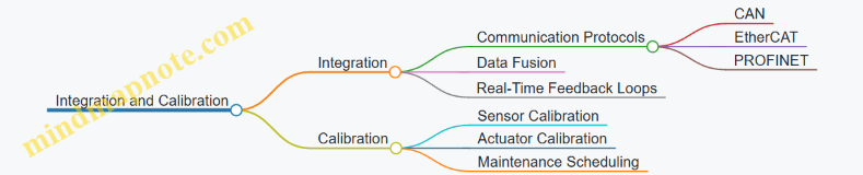
Example: A robotic welding system integrates force sensors and position encoders via EtherCAT protocol to adjust welding pressure in real-time, improving weld quality.
Key Concepts Summary:
-
Precision Motion Control is the backbone of industrial robotics, enabling accurate and repeatable movements through the use of actuators like servo and stepper motors, controlled by sophisticated algorithms such as PID or adaptive control.
-
Sensors provide critical feedback that informs the control system about the robot’s position, force applied, and environmental conditions. Position sensors (encoders, potentiometers), force sensors, and vision systems are fundamental to achieving precision.
-
Sensor Integration involves combining data from multiple sensors using communication protocols and data fusion techniques to create a comprehensive understanding of the robot’s state and surroundings.
-
Calibration and Maintenance ensure that sensors and actuators maintain their accuracy over time. Regular calibration schedules and predictive maintenance reduce downtime and enhance system reliability.
-
Real-World Applications demonstrate how these concepts come together: from automotive assembly lines using multi-axis robots with redundant position sensors to electronics manufacturing employing force sensing for delicate component placement.
Practical Example Recap:
-
Pick-and-Place Robot: Uses servo motors with incremental encoders for precise positioning; vision sensors verify object placement.
-
Robotic Welding: Force sensors and position encoders integrated via EtherCAT enable adaptive control of welding parameters.
-
Pharmaceutical Packaging: Vision systems combined with lighting techniques detect defects and verify labeling accuracy.
By mastering these key concepts, robotics engineers, automation technicians, and manufacturing leads can design, implement, and maintain industrial robotic systems that deliver exceptional precision and reliability.
12.2 Comprehensive Best Practices for Robotics Engineers and Technicians
Industrial robotics demands precision, reliability, and adaptability. To achieve optimal performance in precision motion and sensor integration, robotics engineers and technicians must follow a set of best practices that cover design, implementation, calibration, and maintenance. Below is a detailed guide with mind maps and practical examples to help you master these areas.
Best Practice 1: Systematic Sensor Selection and Integration
- Understand Application Requirements: Identify the precision, speed, and environmental conditions.
- Choose Appropriate Sensor Types: Position, force, vision, proximity, etc.
- Ensure Compatibility: Communication protocols and physical interfaces.
- Plan for Redundancy: Critical systems benefit from backup sensors.
Mind Map: Sensor Selection Process
Example:
In a robotic arm used for electronic component assembly, engineers selected high-resolution absolute encoders for position sensing to ensure repeatability within microns, combined with force sensors calibrated for delicate handling to avoid damaging components.
Best Practice 2: Precision Motion Control Tuning
- Servo Tuning: Adjust PID parameters to minimize overshoot and steady-state error.
- Use Feedforward Control: Anticipate motion demands to improve response.
- Implement Closed-Loop Feedback: Real-time sensor data to correct motion.
- Test Under Realistic Loads: Validate tuning with actual payloads.
Mind Map: Motion Control Tuning
Example:
A pick-and-place robot was experiencing vibration during rapid movements. By tuning the servo PID parameters and adding feedforward control based on load inertia, engineers reduced settling time by 30%, improving cycle time and accuracy.
Best Practice 3: Calibration and Regular Maintenance
- Establish Calibration Schedules: Based on manufacturer recommendations and operational hours.
- Use Traceable Standards: For sensor and actuator calibration.
- Document Calibration Results: Maintain logs for trend analysis.
- Predictive Maintenance: Use sensor data analytics to anticipate failures.
Mind Map: Calibration & Maintenance Workflow
Example:
A manufacturing plant implemented a monthly calibration routine for all force sensors on assembly robots. Over six months, sensor drift was detected early, preventing assembly defects and costly downtime.
Best Practice 4: Robust Sensor-Motion System Integration
- Synchronize Sensor Data with Motion Commands: Ensure real-time feedback loops.
- Implement Data Fusion: Combine multiple sensor inputs for improved accuracy.
- Use Reliable Communication Protocols: EtherCAT, CANopen, or PROFINET.
- Design for Fault Tolerance: Detect and handle sensor failures gracefully.
Mind Map: Sensor-Motion Integration
Example:
In a robotic welding cell, engineers integrated vision sensors with motion controllers using EtherCAT. Real-time image feedback adjusted the robot’s path dynamically, improving weld quality and reducing scrap rates.
Best Practice 5: Safety and Compliance
- Incorporate Sensor-Based Safety Systems: Light curtains, emergency stops, and force limits.
- Follow Industry Standards: ISO 10218 for industrial robots, ISO/TS 15066 for collaborative robots.
- Regular Safety Audits: Validate sensor and motion system safety functions.
Mind Map: Safety Best Practices
Example:
A collaborative robot (cobot) was equipped with force sensors to detect unexpected contact. When excessive force was sensed, the robot stopped immediately, preventing injury and complying with ISO/TS 15066.
Best Practice 6: Continuous Learning and Documentation
- Maintain Detailed Documentation: Design decisions, calibration data, tuning parameters.
- Train Staff Regularly: Updates on new sensor technologies and motion control methods.
- Leverage Simulation Tools: Validate designs before physical deployment.
Mind Map: Continuous Improvement
Example:
A robotics team used simulation software to model a new precision assembly task. By iterating virtually, they optimized sensor placement and motion profiles, reducing commissioning time by 40%.
Summary Table of Best Practices with Examples
| Best Practice | Key Actions | Example Use Case |
|---|---|---|
| Sensor Selection & Integration | Match sensors to task, ensure compatibility | High-res encoders + force sensors in electronics |
| Motion Control Tuning | PID tuning, feedforward, load testing | Vibration reduction in pick-and-place robots |
| Calibration & Maintenance | Scheduled calibration, predictive maintenance | Monthly force sensor calibration in assembly line |
| Sensor-Motion Integration | Real-time feedback, data fusion, fault tolerance | Vision-guided welding with EtherCAT integration |
| Safety and Compliance | Sensor safety systems, standards adherence | Force-limited cobots complying with ISO standards |
| Continuous Learning & Documentation | Training, simulation, detailed logs | Simulation-driven design optimization |
By following these comprehensive best practices, robotics engineers and technicians can ensure high precision, reliability, and safety in industrial robotics applications. These guidelines, supported by practical examples and structured mind maps, provide a clear path to mastering precision motion and sensor integration.
12.3 Practical Tips for Manufacturing Leads to Optimize Robotics Deployment
Manufacturing leads play a pivotal role in ensuring that robotics deployment is efficient, cost-effective, and aligned with production goals. Optimizing robotics deployment requires strategic planning, cross-functional collaboration, and continuous monitoring. Below are practical tips, supported by mind maps and real-world examples, to help manufacturing leads maximize the benefits of industrial robotics.
Assess Production Needs and Define Clear Objectives
- Identify repetitive, hazardous, or precision-critical tasks suitable for automation.
- Set measurable goals such as cycle time reduction, quality improvement, or throughput increase.
Example: A manufacturing lead at an electronics assembly plant identified that soldering was a repetitive and precision-critical task. Deploying a robotic soldering arm reduced defects by 30% and cycle time by 20%.
Collaborate with Cross-Functional Teams Early
- Engage robotics engineers, automation technicians, quality control, and maintenance teams.
- Ensure alignment on requirements, constraints, and deployment timelines.
Example: In an automotive plant, early collaboration helped identify that the robotic welding cell needed additional sensors for quality assurance, preventing costly rework later.
Prioritize Sensor Selection and Calibration
- Choose sensors that match the precision and environmental requirements.
- Implement regular calibration schedules to maintain accuracy.
Example: A food processing facility selected food-grade proximity sensors and established monthly calibration, reducing sensor-related downtime by 15%.
Implement Robust Training Programs
- Train operators and technicians on robot programming, maintenance, and troubleshooting.
- Encourage knowledge sharing and continuous learning.
Example: A manufacturing lead at a packaging plant introduced quarterly training sessions, resulting in a 25% reduction in robot downtime due to operator errors.
Monitor Performance and Use Data Analytics
- Utilize sensor data and motion control feedback to monitor robot health and performance.
- Implement predictive maintenance to avoid unexpected failures.
Example: An electronics manufacturer integrated IoT-enabled sensors with analytics dashboards, enabling early detection of wear in robotic arms and reducing unplanned downtime by 40%.
Plan for Scalability and Flexibility
- Design robotic systems that can be easily reprogrammed or reconfigured for new products or processes.
- Consider modular hardware and software architectures.
Example: A consumer goods manufacturer deployed modular robotic cells that could be quickly adapted for seasonal product changes, minimizing changeover time.
Ensure Safety and Compliance
- Integrate safety sensors and emergency stop mechanisms.
- Comply with industry standards and regulations.
Example: A pharmaceutical manufacturing lead ensured all cobots had integrated force sensors and safety-rated monitored stops, meeting FDA and OSHA requirements.
Summary Mind Map: Optimizing Robotics Deployment for Manufacturing Leads
By following these practical tips, manufacturing leads can significantly enhance the efficiency, reliability, and ROI of their robotics deployments, ensuring their production lines remain competitive and future-ready.
12.4 Example: Checklist for Evaluating and Improving Existing Robotics Systems
Evaluating and improving existing robotics systems is essential to maintain high precision, reliability, and efficiency in industrial environments. This checklist is designed to guide robotics engineers, automation technicians, and manufacturing leads through a systematic review and enhancement process.
Robotics System Evaluation & Improvement Checklist
System Overview and Documentation
- Verify that all system documentation (manuals, wiring diagrams, software versions) is up-to-date.
- Confirm the robot model and specifications match the intended application.
- Check for any undocumented modifications or upgrades.
Precision Motion Performance
- Assess repeatability and accuracy of motion using test runs.
- Measure backlash, hysteresis, and mechanical play in joints.
- Review servo tuning parameters and update PID settings if necessary.
- Inspect mechanical components for wear or damage.
Sensor Functionality and Calibration
- Confirm all sensors (position, force, vision, proximity) are operational.
- Perform calibration routines for encoders, force sensors, and vision systems.
- Check sensor alignment and mounting stability.
- Validate sensor data accuracy against known standards.
Control System and Software
- Verify firmware and software are current and compatible.
- Review control algorithms for motion planning and sensor fusion.
- Test communication protocols and data integrity between sensors and controllers.
- Check for error logs or recurring faults.
Safety and Compliance
- Inspect emergency stop systems and safety interlocks.
- Ensure sensors related to safety (e.g., light curtains, proximity sensors) are functioning.
- Review compliance with industry standards (ISO, ANSI).
Maintenance and Environment
- Review maintenance logs and schedules.
- Check for environmental factors affecting performance (temperature, dust, vibration).
- Assess lubrication and mechanical condition.
Performance Metrics and Continuous Improvement
- Collect data on cycle times, downtime, and defect rates.
- Identify bottlenecks or inconsistencies in operation.
- Plan upgrades or retrofits based on data-driven insights.
Mind Map: Robotics System Evaluation Checklist
Mind Map: Improvement Strategies
Practical Examples
Example 1: Improving Position Accuracy in a Pick-and-Place Robot
- Issue: The robot was experiencing a 0.5 mm deviation in placement accuracy.
- Evaluation: Servo tuning parameters were outdated; encoders showed slight drift.
- Improvement: Recalibrated encoders, updated PID settings, and replaced worn bearings.
- Result: Placement accuracy improved to within 0.1 mm, reducing product defects.
Example 2: Enhancing Sensor Reliability in a Welding Robot
- Issue: Vision sensor intermittently failed to detect weld seams.
- Evaluation: Sensor lens was dirty; lighting conditions were inconsistent.
- Improvement: Installed automated lens cleaning system and optimized lighting setup.
- Result: Sensor reliability increased, reducing weld defects by 15%.
Example 3: Reducing Downtime Through Predictive Maintenance
- Issue: Unexpected robot stoppages due to motor overheating.
- Evaluation: Maintenance logs showed irregular checks; temperature sensors were not monitored.
- Improvement: Implemented temperature sensors with real-time monitoring and scheduled maintenance alerts.
- Result: Downtime reduced by 30%, improving overall productivity.
Summary
This checklist and associated mind maps provide a structured approach to systematically evaluate and improve existing industrial robotics systems. By addressing mechanical, sensor, control, safety, and maintenance aspects, teams can ensure optimal precision motion and sensor performance, ultimately enhancing manufacturing quality and efficiency.
12.5 Final Thoughts: Continuous Improvement in Industrial Robotics
Continuous improvement is the cornerstone of maintaining and advancing the capabilities of industrial robotics, especially in the realms of precision motion and sensor integration. As robotics engineers, automation technicians, and manufacturing leads, embracing a mindset of ongoing enhancement ensures systems remain efficient, reliable, and competitive.
Why Continuous Improvement Matters
- Adaptation to Technological Advances: Robotics technology evolves rapidly, with new sensors, control algorithms, and materials emerging regularly.
- Maintaining Precision and Accuracy: Over time, mechanical wear, sensor drift, and environmental changes can degrade performance.
- Optimizing Productivity: Continuous tuning and upgrades can reduce cycle times and improve throughput.
- Enhancing Safety: Regular updates and improvements help prevent accidents and ensure compliance with safety standards.
Key Areas for Continuous Improvement
Practical Examples of Continuous Improvement
-
Example: Servo Motor Re-Tuning in a Packaging Robot
- After six months of operation, a packaging robot begins showing slight positioning errors.
- Engineers perform servo tuning by adjusting PID parameters and recalibrating encoders.
- Result: Improved accuracy by 15%, reducing product defects.
-
Example: Sensor Fusion Upgrade in Automotive Welding
- Original system used only position encoders.
- Integration of force sensors and vision systems enabled real-time adaptive welding.
- Result: Enhanced weld quality and reduced rework by 20%.
-
Example: Predictive Maintenance Using Sensor Data Analytics
- Vibration and temperature sensors on robotic arms feed data to analytics software.
- Early detection of bearing wear allows preemptive replacement.
- Result: Avoided unexpected downtime and costly repairs.
Strategies to Foster Continuous Improvement
Final Example: Implementing a Continuous Improvement Cycle
A mid-sized electronics manufacturer implemented a continuous improvement cycle for their precision robotic assembly line:
- Plan: Identified key performance indicators (KPIs) such as cycle time and defect rate.
- Do: Scheduled monthly calibration of sensors and servo systems.
- Check: Used data analytics dashboards to monitor KPIs.
- Act: Adjusted control parameters and retrained staff based on insights.
Outcome: Over one year, the line saw a 25% increase in throughput and a 30% reduction in defects.
Conclusion
Continuous improvement in industrial robotics is not a one-time effort but a persistent journey. By systematically tuning motion control, refining sensor accuracy, leveraging data analytics, and investing in workforce skills, organizations can sustain and elevate their robotics systems’ precision and reliability. Embracing this philosophy ensures that industrial robotics remain a powerful enabler of manufacturing excellence well into the future.