Electric Aircraft Propulsion Fundamentals
1. Introduction to Electric Aircraft Propulsion
1.1 Overview of Electric Propulsion Systems in Aviation
Electric propulsion systems in aviation replace or supplement traditional combustion engines with electric motors to generate thrust. These systems consist primarily of electric motors, power electronics (inverters and controllers), energy storage or generation units (batteries, fuel cells, or hybrid sources), and the mechanical components that transfer power to propellers or fans.
At the core, electric propulsion aims to convert electrical energy into mechanical energy efficiently and reliably to propel an aircraft. Unlike combustion engines, electric motors provide instant torque and can be more compact and lighter for the same power output, which is critical in aviation where weight and efficiency are paramount.
Key Components of Electric Propulsion Systems
- Electric Motor: Converts electrical energy into mechanical rotation.
- Power Electronics/Inverter: Controls motor speed and torque by converting DC power to AC and managing current and voltage.
- Energy Source: Batteries, fuel cells, or hybrid systems supply electrical power.
- Thermal Management: Maintains optimal operating temperatures for motors and electronics.
- Mechanical Transmission: Connects the motor to the propeller or fan.
Mind Map: Components of Electric Propulsion Systems
Types of Electric Propulsion Architectures
- All-Electric: Powered solely by batteries or fuel cells.
- Hybrid-Electric: Combines combustion engines with electric motors to optimize efficiency.
- Distributed Electric Propulsion: Multiple smaller electric motors distributed across the airframe.
Each architecture has trade-offs in complexity, weight, and energy density. For example, all-electric systems simplify mechanical design but face energy storage limitations, while hybrid systems add complexity but extend range.
Example: Simple All-Electric Propulsion System
Consider a small trainer aircraft equipped with a brushless DC motor powered by lithium-ion batteries. The motor drives a propeller directly without a gearbox. The inverter controls motor speed based on pilot input. Thermal management uses air cooling via ducts. This setup reduces moving parts compared to piston engines and offers smoother operation.
Mind Map: All-Electric Propulsion Example
Performance Considerations
- Power Density: Electric motors can achieve higher power-to-weight ratios than combustion engines, but this depends on design and cooling.
- Efficiency: Electric motors often exceed 90% efficiency, reducing energy waste.
- Response Time: Instant torque allows for precise thrust control.
- Noise: Electric propulsion tends to produce less noise, improving comfort and reducing environmental impact.
Challenges in Electric Propulsion
- Energy Storage: Batteries have lower energy density than aviation fuels, limiting range.
- Thermal Management: High power density generates heat that must be effectively dissipated.
- Weight: Balancing motor power, battery weight, and structural requirements is critical.
Example: Distributed Electric Propulsion in a UAV
A UAV uses six small electric motors mounted on the wings. Each motor drives a propeller controlled independently for redundancy and maneuverability. This setup allows for efficient lift distribution and improved control but requires complex power electronics and thermal management.
Mind Map: Distributed Electric Propulsion UAV
In summary, electric propulsion systems in aviation integrate multiple components to convert electrical energy into thrust efficiently. Understanding the components, architectures, and practical examples helps clarify how these systems function and what design considerations are involved.
1.2 Key Components and Their Roles
Electric aircraft propulsion systems consist of several critical components, each with a defined role that contributes to the overall function and efficiency of the propulsion system. Understanding these components and how they interact is essential for designing, operating, and maintaining electric propulsion systems.
Main Components Overview
- Electric Motor: Converts electrical energy into mechanical energy to drive the propeller.
- Inverter: Converts DC electrical power from the battery into AC power suitable for the motor.
- Battery or Energy Storage System: Supplies electrical energy to the propulsion system.
- Thermal Management System: Maintains optimal operating temperatures for motors, inverters, and batteries.
- Control System: Manages motor speed, torque, and system safety.
- Propeller: Converts mechanical energy from the motor into thrust.
Mind Map: Core Components and Their Functions
Electric Motor
The motor is the heart of the propulsion system. It transforms electrical energy into rotational mechanical energy to spin the propeller. High power density motors are preferred in aviation to reduce weight and volume. Common motor types include brushless DC (BLDC) and permanent magnet synchronous motors (PMSM). Each type has trade-offs in efficiency, complexity, and thermal management.
Example: A brushless DC motor with rare-earth magnets can provide high torque at low weight, making it suitable for small electric aircraft. Its design minimizes friction losses and maintenance needs.
Inverter
The inverter acts as the translator between the battery and the motor. Since batteries supply direct current (DC), and most high-performance motors require alternating current (AC), the inverter converts DC to AC. It also controls the frequency and amplitude of the AC signal, which determines the motor speed and torque.
Example: A three-phase inverter uses semiconductor switches (like IGBTs or MOSFETs) to generate AC waveforms. By adjusting the switching pattern, it can smoothly control motor speed during takeoff and cruise.
Battery or Energy Storage System
The battery stores electrical energy and delivers it to the propulsion system. It must provide high power output while being lightweight and safe. Lithium-ion batteries are common due to their energy density and cycle life.
Example: A battery pack designed for a light electric aircraft might include multiple cells arranged in series and parallel to achieve the required voltage and capacity, with built-in sensors to monitor temperature and voltage.
Thermal Management System
Electric propulsion components generate heat during operation. Excess heat reduces efficiency and can damage components. Thermal management systems remove this heat to keep components within safe operating temperatures.
Example: Liquid cooling channels integrated into the motor housing can effectively remove heat from stator windings, while heat sinks and fans cool the inverter electronics.
Control System
The control system governs the operation of the propulsion system. It regulates motor speed and torque based on pilot inputs and flight conditions. It also monitors system health and implements safety protocols.
Example: Field-oriented control (FOC) algorithms allow precise control of motor torque and speed, improving efficiency and responsiveness.
Propeller
The propeller converts the motor’s mechanical energy into thrust. Its design affects overall propulsion efficiency and noise. Blade shape, pitch, and number influence performance.
Example: A variable-pitch propeller can adjust blade angle during flight to optimize thrust and efficiency at different speeds.
Mind Map: Interaction Between Components
Integrated Example: Small Electric Aircraft Propulsion
Consider a small electric trainer aircraft:
- The battery pack delivers 400 V DC to the inverter.
- The inverter converts this to a three-phase AC signal at variable frequency.
- The PMSM motor receives the AC power, spinning the propeller at speeds from 1000 to 3000 RPM.
- A liquid cooling system circulates coolant through the motor housing and inverter heat sinks.
- The control system adjusts motor speed based on throttle input and monitors temperatures.
- The propeller’s fixed pitch is optimized for cruise efficiency.
This example shows how components work together, each with a clear role, to achieve reliable propulsion.
Understanding these key components and their roles lays the groundwork for deeper study into design, control, and integration of electric aircraft propulsion systems.
1.3 Advantages of Electric Propulsion over Conventional Systems
Electric propulsion systems offer several advantages over conventional combustion-based aircraft propulsion. These advantages stem from fundamental differences in how power is generated, converted, and utilized. Understanding these benefits helps clarify why electric propulsion is gaining attention in aviation.
Efficiency
Electric motors convert electrical energy into mechanical energy with efficiencies often exceeding 90%, whereas internal combustion engines typically operate between 30% and 40% efficiency. This means more of the input energy is effectively used for propulsion, reducing waste.
Example: A typical small aircraft engine might burn 10 gallons of fuel per hour, while an electric motor powered by a battery or fuel cell can deliver equivalent thrust with less energy input due to higher efficiency.
Reduced Mechanical Complexity
Electric motors have fewer moving parts compared to combustion engines. They lack components like pistons, valves, and complex gearboxes, which simplifies maintenance and reduces points of failure.
Example: An electric motor’s rotor and stator are the main mechanical elements, while a piston engine has dozens of moving parts requiring regular inspection and replacement.
Instant Torque and Throttle Response
Electric motors provide maximum torque from zero RPM, allowing for rapid acceleration and precise control. This contrasts with combustion engines, which need to reach certain RPMs to deliver peak torque.
Example: During takeoff, an electric motor can quickly ramp up power, improving responsiveness and potentially reducing runway length requirements.
Lower Noise and Vibration
Electric propulsion systems produce less noise and vibration because they operate smoothly without combustion pulses or complex mechanical linkages. This improves passenger comfort and reduces noise pollution.
Example: Electric motors emit a steady hum rather than the loud roar of a piston or turbine engine, making them suitable for urban or noise-sensitive areas.
Emissions and Environmental Impact
Electric propulsion produces zero local emissions when powered by batteries or clean energy sources. This contrasts with combustion engines that emit CO2, NOx, and particulates during operation.
Example: An electric aircraft operating in a city center produces no exhaust gases, improving air quality around airports.
Scalability and Modularity
Electric propulsion components can be scaled and arranged modularly. Multiple smaller motors can replace a single large engine, offering redundancy and design flexibility.
Example: Distributed electric propulsion uses several smaller motors along the wing, improving aerodynamic efficiency and providing backup in case of motor failure.
Energy Source Flexibility
Electric propulsion can use various energy sources: batteries, fuel cells, or hybrid systems. This flexibility allows adaptation to different mission profiles and energy availability.
Example: A commuter aircraft might use batteries for short flights, while a regional aircraft could combine fuel cells with batteries for longer range.
Summary Mind Map
Each of these advantages contributes to a propulsion system that is simpler, cleaner, and often more responsive than traditional combustion engines. Real-world examples, such as electric drones and small electric aircraft, illustrate these benefits in operation, showing how electric propulsion can meet the demands of sustainable aviation without compromising performance or reliability.
1.4 Challenges in High Power Density Applications
High power density in electric aircraft propulsion means packing a lot of power into a small, lightweight package. This is essential for aviation, where every kilogram counts. However, achieving this balance introduces several technical challenges that affect design, reliability, and performance.
Thermal Management
When motors and inverters operate at high power density, they generate significant heat in a confined space. Excess heat reduces efficiency, accelerates material degradation, and can cause failure if not managed properly.
- Example: A brushless DC motor designed for a small electric aircraft might produce several kilowatts of heat during peak operation. Without effective cooling, the motor winding insulation could degrade rapidly.
Mind Map: Thermal Management Challenges
Electromagnetic Design Constraints
To increase power density, designers push magnetic materials and windings to their limits. This can cause increased magnetic saturation, higher losses, and electromagnetic interference (EMI).
- Example: Using rare-earth magnets with higher flux density improves torque but risks demagnetization if the motor overheats or experiences high currents.
Mind Map: Electromagnetic Design Challenges
Mechanical and Structural Issues
High power density motors must withstand mechanical stresses from rotation, vibration, and thermal expansion. Lightweight materials may lack the robustness needed for long-term durability.
- Example: A high-speed motor rotor made from carbon fiber composites reduces weight but requires careful balancing to avoid destructive vibrations.
Mind Map: Mechanical Challenges
Electrical and Control Challenges
Operating at high power densities demands precise control to avoid damaging currents and voltages. Fast switching in inverters can cause voltage spikes and electromagnetic noise.
- Example: A three-phase inverter driving a high power motor must implement advanced pulse-width modulation (PWM) techniques to maintain smooth torque and limit switching losses.
Mind Map: Electrical and Control Challenges
Integration and Packaging Constraints
Fitting motors, inverters, and cooling systems into limited aircraft space while maintaining accessibility for maintenance is tricky. Weight distribution and electromagnetic compatibility also come into play.
- Example: Placing the inverter close to the motor reduces cable losses but increases thermal coupling, requiring integrated cooling solutions.
Mind Map: Integration Challenges
Reliability and Safety
High power density systems operate closer to material and thermal limits, increasing the risk of failure. Designing for fault tolerance and safe shutdown is critical.
- Example: Implementing redundant temperature sensors and current monitoring can help detect early signs of motor winding overheating.
Mind Map: Reliability and Safety Challenges
Summary Example: Designing a High Power Density Motor
Consider a 100 kW motor for a light electric aircraft. To achieve high power density, the design uses high-grade neodymium magnets, compact winding arrangements, and a liquid cooling jacket. The design team must balance magnetic saturation against thermal limits, ensure mechanical integrity at high RPM, and implement an inverter with fast switching and robust control algorithms. Thermal sensors are embedded at critical points to monitor temperature in real time. The integration places the inverter adjacent to the motor to minimize cable losses but requires a shared cooling system to handle combined heat loads.
This example illustrates how each challenge interacts and why addressing them together is essential for a successful high power density electric propulsion system.
1.5 Best Practices for System Integration with Practical Examples
System integration in electric aircraft propulsion involves combining motors, inverters, batteries, and thermal management into a cohesive unit that performs reliably under demanding conditions. Best practices focus on ensuring compatibility, minimizing losses, managing heat effectively, and maintaining safety margins. Here, we break down key considerations with practical examples and mind maps to clarify the process.
Key Areas of System Integration
Electrical Compatibility
Ensuring that the motor, inverter, and battery operate within compatible voltage and current ranges is fundamental. For example, if a motor is rated for 400 V DC and the inverter output matches this, the battery pack must also supply this voltage under load without excessive voltage sag.
Example: A 200 kW motor designed for 400 V operation is paired with an inverter rated for 450 V max input and a battery pack nominally at 400 V. The inverter’s margin allows for transient voltage spikes without damage. Connectors are selected to handle peak currents of 500 A with low resistance to reduce losses.
Mechanical Integration
The physical connection between motor and propeller, and the mounting of the motor-inverter assembly, must consider vibration, alignment, and weight distribution. Poor alignment can cause bearing wear and noise.
Example: A brushless motor is mounted on vibration-damping mounts that reduce transmission of propeller-induced vibrations to the airframe. The motor shaft is aligned using laser measurement tools to ensure concentricity within 0.1 mm, preventing premature wear.
Thermal Management
Heat generated by the motor and inverter must be removed efficiently to maintain performance and avoid damage. Integration should include thermal interfaces and coolant pathways designed to handle expected heat loads.
Example: The inverter is mounted on a liquid-cooled cold plate directly attached to the motor housing. Thermal interface material with high conductivity fills microscopic gaps, reducing thermal resistance. Temperature sensors at critical points feed data to the control system for active cooling adjustments.
Control and Communication
Signal wiring for motor control and feedback must be shielded and routed to minimize electromagnetic interference. Control algorithms rely on accurate sensor data to maintain performance and safety.
Example: Hall effect sensors and temperature probes use twisted-pair shielded cables routed separately from high-current lines. The control unit implements fault detection algorithms that monitor sensor signals for anomalies, triggering safe shutdown if needed.
Safety and Redundancy
Redundancy in critical components and clear fault isolation paths enhance safety. Emergency shutdown mechanisms must be integrated and tested.
Example: Dual independent current sensors monitor motor current. If one sensor fails or detects an overcurrent, the system triggers an emergency stop. Mechanical relays isolate the battery pack from the inverter during faults.
Practical Integration Example: Small Electric Aircraft Propulsion System
In this example, the battery pack voltage matches the motor and inverter ratings, ensuring electrical compatibility. The liquid cooling loop connects the motor and inverter cold plates to a heat exchanger on the airframe, maintaining temperature within operational limits. Vibration isolators reduce mechanical stress on the airframe and components. The control system uses sensor feedback to adjust motor torque and monitor temperature, enabling safe and efficient operation.
Mind Map: Integration Workflow
Summary
Effective system integration balances electrical, mechanical, thermal, and control aspects to create a propulsion system that is reliable, efficient, and safe. Practical examples highlight how matching component ratings, managing heat, isolating vibrations, and implementing robust control and safety features come together in a working system. Mind maps help visualize the complex relationships and steps involved, making integration more manageable and systematic.
2. Fundamentals of Electric Motors for Aircraft
2.1 Motor Types Suitable for Aviation Applications
Electric motors in aircraft propulsion must balance power density, efficiency, reliability, and weight. Different motor types offer distinct advantages and trade-offs. This section covers the main motor types used or considered for electric aircraft propulsion, with examples and mind maps to clarify their characteristics.
Core Motor Types
- Brushed DC Motors
- Brushless DC Motors (BLDC)
- Permanent Magnet Synchronous Motors (PMSM)
- Induction Motors (Asynchronous Motors)
- Switched Reluctance Motors (SRM)
Mind Map: Overview of Motor Types for Aviation
Brushed DC Motors
Brushed DC motors use brushes and a commutator to switch current in the rotor windings. This design is simple and easy to control but suffers from wear and maintenance issues due to brush friction. Their power density is relatively low, and they are less suitable for high-speed, high-power applications typical in aircraft propulsion. They are mostly found in small, low-power applications or legacy systems.
Example: A small electric trainer aircraft might use a brushed DC motor for ground taxiing systems but not for main propulsion.
Brushless DC Motors (BLDC)
BLDC motors eliminate brushes by using electronic commutation. They typically have permanent magnets on the rotor and windings on the stator. This design reduces maintenance and improves efficiency. BLDC motors offer a good power-to-weight ratio and are widely used in electric aircraft propulsion.
They provide high torque at low speeds and maintain efficiency over a broad speed range. Their electronic control allows precise speed and torque management.
Example: The Pipistrel Alpha Electro uses BLDC motors for its propulsion system, benefiting from their reliability and efficiency.
Permanent Magnet Synchronous Motors (PMSM)
PMSMs are similar to BLDC motors but produce sinusoidal back-EMF, resulting in smoother torque output and less noise. They use high-strength permanent magnets, often rare-earth types, which contribute to high power density.
PMSMs require sophisticated control algorithms, such as field-oriented control, to optimize performance. Their efficiency and power density make them a strong candidate for electric aircraft propulsion.
Example: A regional electric aircraft prototype might use a PMSM to achieve higher cruise efficiency and reduce vibration.
Induction Motors
Induction motors do not use permanent magnets; instead, they induce current in the rotor windings via electromagnetic induction. They are robust, inexpensive, and have good thermal characteristics.
However, their power density is generally lower than permanent magnet motors, and they require more complex control to achieve high efficiency. They are less common in aviation propulsion due to weight and efficiency constraints.
Example: Induction motors are more common in industrial applications but have been tested in some UAV propulsion systems where cost and robustness are priorities.
Switched Reluctance Motors (SRM)
SRMs have a simple and rugged construction with salient poles on both rotor and stator. They do not use permanent magnets or brushes. Their torque production relies on the tendency of the rotor to align with the stator’s energized poles.
SRMs can operate at high speeds and temperatures, but they suffer from torque ripple and acoustic noise. Control complexity is higher due to the nonlinear magnetic characteristics.
Example: Some experimental electric aircraft propulsion systems have tested SRMs for their mechanical simplicity and tolerance to harsh environments.
Mind Map: Comparison of Motor Types
Summary
For electric aircraft propulsion, permanent magnet machines (BLDC and PMSM) dominate due to their high power density and efficiency. Induction and switched reluctance motors offer robustness and lower cost but at the expense of weight or control complexity. Brushed DC motors are generally unsuitable for main propulsion due to maintenance and performance limitations.
Choosing a motor type involves balancing efficiency, weight, reliability, control complexity, and cost. Real-world examples show that BLDC and PMSM motors are the current practical choices for sustainable electric aviation propulsion.
2.2 Electromagnetic Principles and Motor Operation
Electric motors convert electrical energy into mechanical energy using electromagnetic forces. This section explains the fundamental electromagnetic principles behind motor operation and illustrates how these principles apply to aircraft propulsion motors.
Basic Electromagnetic Concepts
At the core of motor operation are magnetic fields and forces generated by electric currents. When current flows through a conductor, it creates a magnetic field around it. Conversely, a conductor moving within a magnetic field experiences a force. These interactions form the basis of motor torque production.
- Magnetic Field (B): A vector field representing magnetic influence, measured in Tesla (T).
- Electric Current (I): Flow of electric charge, measured in Amperes (A).
- Lorentz Force (F): The force on a charged particle moving in a magnetic field, given by \( \mathbf{F} = q(\mathbf{v} \times \mathbf{B}) \).
In motors, the Lorentz force acts on current-carrying conductors within magnetic fields, producing torque.
Motor Components and Magnetic Interaction
A typical electric motor has two main parts:
- Stator: The stationary part, usually containing coils that generate a rotating magnetic field when energized.
- Rotor: The rotating part, which interacts with the stator’s magnetic field to produce motion.
The stator creates a magnetic field that changes position or polarity, inducing forces on the rotor. The rotor responds by turning, aligning with the magnetic field.
Electromagnetic Torque Production
Torque in an electric motor arises from the interaction between the magnetic field and current in the rotor windings or permanent magnets. The torque \( T \) can be expressed as:
\[ T = k_t \cdot I \cdot \Phi \]
where:
- \( k_t \) is the torque constant,
- \( I \) is the current,
- \( \Phi \) is the magnetic flux.
Increasing current or magnetic flux increases torque, but practical limits exist due to heating and magnetic saturation.
Electromagnetic Induction and Back EMF
When the rotor spins, it cuts through magnetic field lines, inducing a voltage opposing the supply voltage, known as back electromotive force (back EMF). Back EMF limits the current as speed increases, stabilizing motor operation.
The back EMF \( E_b \) is proportional to rotor speed \( \omega \):
\[ E_b = k_e \cdot \omega \]
where \( k_e \) is the back EMF constant.
Mind Map: Electromagnetic Principles in Motor Operation
Example 1: Simple Brushless DC Motor Operation
Consider a brushless DC motor with three stator windings energized sequentially to create a rotating magnetic field. The rotor contains permanent magnets. As the stator field rotates, the rotor magnets align to minimize magnetic reluctance, causing the rotor to spin.
- When winding A is energized, the rotor aligns with that field.
- Energizing winding B next pulls the rotor forward.
- Sequential energizing creates continuous rotation.
Back EMF generated by the rotor speed limits current, preventing runaway acceleration.
Example 2: Torque Calculation in a Motor
Suppose a motor has a torque constant \( k_t = 0.1 , \text{Nm/A} \), magnetic flux \( \Phi = 0.05 , \text{Wb} \), and current \( I = 50 \text{A} \).
Torque produced:
\[ T = 0.1 \times 50 \times 0.05 = 0.25 \text{Nm} \]
This torque drives the propeller, converting electrical input into mechanical thrust.
Summary
Understanding electromagnetic principles clarifies how electric motors generate torque and respond to electrical inputs. The interplay between magnetic fields, current, and induced voltages governs motor behavior. These fundamentals guide the design of high power density motors for aircraft propulsion, balancing torque, speed, and efficiency.
2.3 Design Parameters Affecting Power Density and Efficiency
Power density and efficiency are two critical metrics in electric motor design for aircraft propulsion. Power density refers to the amount of power a motor can produce relative to its size or weight, while efficiency measures how well the motor converts electrical energy into mechanical energy. Both parameters are influenced by a range of design choices, often with trade-offs between them. Understanding these parameters helps engineers optimize motors for the demanding requirements of aviation.
Key Design Parameters
-
Magnetic Flux Density: The strength of the magnetic field in the motor’s air gap directly affects torque production. Higher flux density can increase power density but risks magnetic saturation, which reduces efficiency.
-
Current Density: The amount of current per unit cross-sectional area of the conductor influences torque and losses. Increasing current density raises power output but also increases resistive heating, impacting thermal management.
-
Slot and Pole Count: The number of stator slots and rotor poles affects the motor’s torque ripple, efficiency, and power density. More poles can improve torque but may increase complexity and losses.
-
Air Gap Length: A smaller air gap improves magnetic coupling and torque but tight tolerances increase manufacturing difficulty and mechanical risk.
-
Winding Configuration: Choices between distributed or concentrated windings affect copper losses, inductance, and thermal dissipation.
-
Material Selection: Using high-grade electrical steel and permanent magnets with strong remanence improves magnetic performance and efficiency.
-
Cooling Method: Efficient heat removal allows higher current densities, increasing power density without overheating.
-
Mechanical Design Constraints: Rotor inertia and structural integrity limit how aggressively dimensions can be reduced.
Mind Map: Design Parameters Impacting Power Density and Efficiency
Example 1: Balancing Current Density and Cooling
Consider a brushless DC motor designed for a small electric aircraft. The designer wants to increase the current density to boost torque output. However, raising current density from 5 A/mm² to 10 A/mm² doubles the resistive losses, which can cause the winding temperature to exceed safe limits. To manage this, the cooling system is upgraded from passive air cooling to liquid cooling. This change allows the motor to safely operate at the higher current density, effectively increasing power density without sacrificing reliability.
Example 2: Choosing Slot and Pole Count for Efficiency
A motor with 12 stator slots and 10 rotor poles might generate smooth torque but suffer from higher iron losses due to increased magnetic harmonics. Switching to a 9-slot, 8-pole configuration reduces these losses, improving efficiency by about 2%. However, this configuration may produce more torque ripple, which requires additional control strategies to smooth out. The trade-off here is between raw efficiency and control complexity.
Mind Map: Trade-offs in Design Parameters
Example 3: Air Gap and Manufacturing Precision
Reducing the air gap from 1 mm to 0.5 mm improves the motor’s magnetic coupling, increasing torque output by roughly 10%. However, maintaining such a small gap requires precise manufacturing and assembly techniques. Any rotor eccentricity or vibration can cause the rotor to contact the stator, risking damage. The designer must weigh the performance gain against the increased production cost and risk.
Summary
Design parameters in electric aircraft motors interact in complex ways. Increasing power density often means pushing materials and cooling systems to their limits, which can reduce efficiency or reliability if not managed properly. Efficiency improvements can come from better materials or winding configurations but might complicate manufacturing or control. The best designs find a balance that meets performance goals while ensuring safety and durability.
2.4 Materials Selection for High Performance Motors
Selecting materials for high performance electric motors in aircraft is a balancing act between electrical, mechanical, thermal, and economic factors. Each component of the motor—rotor, stator, windings, insulation, magnets, and structural parts—requires materials chosen to optimize performance under demanding conditions.
Key Material Categories and Their Roles
- Magnetic Materials: Influence motor efficiency and power density.
- Conductors: Carry current with minimal losses.
- Insulation: Prevent electrical shorts and withstand thermal and mechanical stresses.
- Structural Materials: Provide mechanical integrity and thermal management.
Magnetic Materials
The core of the motor relies on magnetic materials to channel and concentrate magnetic flux. The most common are electrical steels, often called silicon steels, which come in various grades.
-
Grain-Oriented vs. Non-Oriented Steel:
- Grain-oriented steel has high magnetic permeability along a specific direction, ideal for transformers but less so for motors where flux rotates.
- Non-oriented steel offers isotropic magnetic properties, better suited for rotating machines.
-
Key Properties:
- Magnetic Permeability: Higher values reduce core losses.
- Core Losses: Lower hysteresis and eddy current losses improve efficiency.
- Thickness: Thinner laminations reduce eddy currents but increase manufacturing complexity.
Example: A motor designer selects M19 grade non-oriented electrical steel with 0.35 mm lamination thickness to balance low core losses and manufacturability for a brushless DC motor.
Conductors
Copper is the standard conductor due to its excellent electrical conductivity and mechanical properties. Aluminum is sometimes used for weight savings but at the cost of higher resistivity.
-
Copper:
- High conductivity (~58 MS/m).
- Good mechanical strength.
- Higher density (8.96 g/cm³) means heavier windings.
-
Aluminum:
- Lower conductivity (~37 MS/m).
- Lighter (2.7 g/cm³).
- Requires larger cross-section to carry the same current.
Example: In a high power density motor where weight is critical, copper windings are preferred despite the weight penalty because the smaller conductor size reduces overall volume and improves thermal conduction.
Insulation Materials
Insulation must withstand high voltages, thermal cycling, and mechanical vibration. Common insulation types include enamel coatings on wires, slot liners, and impregnation resins.
- Wire Enamel: Thin polymer coatings that electrically isolate individual strands.
- Slot Liners: Sheets or films placed between stator teeth and windings to prevent shorts.
- Impregnation Resins: Epoxy or polyester resins that bind windings and improve thermal conductivity.
Example: A motor operating at 200°C uses polyimide enamel on copper wire and a mica-based slot liner to maintain insulation integrity under thermal stress.
Permanent Magnets
For motors using permanent magnets, material choice affects flux density, temperature stability, and demagnetization resistance.
- Neodymium-Iron-Boron (NdFeB): High energy product, but sensitive to temperature.
- Samarium-Cobalt (SmCo): Lower energy product but better temperature stability and corrosion resistance.
Example: A motor designed for sustained operation at 150°C uses SmCo magnets to avoid irreversible demagnetization.
Structural Materials
Structural parts like the rotor shaft, stator frame, and housing must provide mechanical strength and assist in heat dissipation.
- Aluminum Alloys: Lightweight and good thermal conductivity.
- Steel Alloys: High strength but heavier and lower thermal conductivity.
- Composite Materials: Used for weight savings but require careful thermal design.
Example: An aircraft motor housing made from aluminum alloy 6061-T6 balances weight and thermal management, allowing efficient heat transfer to cooling systems.
Mind Map: Materials Selection for High Performance Motors
Practical Example: Material Selection for a 100 kW Brushless DC Motor
- Magnetic Core: M19 non-oriented electrical steel, 0.35 mm laminations to reduce core losses.
- Windings: Copper wire with polyimide enamel for thermal resistance up to 200°C.
- Insulation: Mica-based slot liners and epoxy resin impregnation for mechanical stability.
- Magnets: NdFeB magnets with a temperature rating of 120°C, chosen for high flux density.
- Housing: Aluminum alloy 6061-T6 for lightweight and effective heat dissipation.
This combination balances efficiency, thermal management, and weight, suitable for a light aircraft application.
Summary
Material selection in high performance electric motors is a multidimensional problem. Magnetic materials affect efficiency and losses, conductors influence electrical performance and weight, insulation ensures reliability under stress, magnets determine flux strength and temperature tolerance, and structural materials provide mechanical support and heat transfer. Each choice involves trade-offs that must align with the motor’s intended operating environment and performance goals.
2.5 Case Study: Designing a High Power Density Brushless DC Motor
This case study walks through the design process of a high power density brushless DC (BLDC) motor intended for electric aircraft propulsion. The goal is to balance power output, weight, efficiency, and thermal management within the constraints typical of aviation applications.
Step 1: Define Design Requirements
- Power Output: 100 kW continuous power
- Voltage: 400 V DC bus
- Speed Range: 0 to 10,000 RPM
- Weight Target: Under 25 kg
- Cooling: Liquid cooling capability
- Efficiency: Above 95% at cruise
These requirements set the stage for motor topology, materials, and thermal design choices.
Step 2: Choose Motor Topology
Brushless DC motors come in several configurations. For high power density, a surface-mounted permanent magnet (SPM) synchronous motor is a common choice due to its simplicity and high efficiency.
Mind Map: Motor Topology Selection
Step 3: Determine Electromagnetic Design Parameters
- Number of Poles: 8 poles (4 pole pairs) to balance torque and speed
- Stator Slots: 24 slots for smooth torque and reduced cogging
- Magnet Material: NdFeB (Neodymium Iron Boron) for high energy product
The pole and slot combination affects torque ripple and efficiency. An 8-pole, 24-slot design offers a good compromise.
Example:
Calculating the electrical frequency at max speed:
\[ f_e = \frac{P}{2} \times N \]
Where:
- \( P \) = number of poles = 8
- \( N \) = mechanical speed in revolutions per second = \( \frac{10,000}{60} \approx 166.67 \) rps
\[ f_e = \frac{8}{2} \times 166.67 = 4 \times 166.67 = 666.68 \text{ Hz} \]
This frequency guides inverter switching frequency and core material selection.
Step 4: Select Materials
- Stator Core: Silicon steel laminations to reduce eddy current losses
- Windings: High purity copper wire with high temperature insulation
- Magnets: Grade N52 NdFeB for high flux density
Material choices impact thermal performance and efficiency.
Step 5: Winding Configuration
- Winding Type: Distributed winding to reduce harmonics
- Turns per Coil: 10 turns (example value based on voltage and current requirements)
- Wire Gauge: AWG 14 to handle current density without excessive heating
Mind Map: Winding Design
Step 6: Thermal Design Considerations
- Cooling Method: Liquid cooling channels integrated into stator
- Thermal Conductivity: Use of thermally conductive epoxy and insulation
- Temperature Limits: Max winding temperature 150°C
Thermal simulations ensure that the motor can dissipate heat generated under continuous operation.
Step 7: Mechanical Design
- Rotor Diameter: 150 mm
- Stack Length: 80 mm
- Shaft Design: High strength steel with keyway for propeller mounting
Mechanical design must consider centrifugal forces at 10,000 RPM.
Step 8: Performance Estimation
- Torque Calculation:
Using the formula:
\[ T = \frac{P}{\omega} \]
Where:
- \( P = 100,000 \) W
- \( \omega = 2 \pi \times 166.67 = 1047.2 \) rad/s
\[ T = \frac{100,000}{1047.2} \approx 95.5 \text{ Nm} \]
- Current Estimation:
Assuming a back-EMF constant \( k_e \) of 0.1 V/rpm,
Back-EMF at 10,000 rpm:
\[ E = k_e \times N = 0.1 \times 10,000 = 1,000 \text{ V} \]
This is higher than the bus voltage, so the motor constant must be adjusted or gearing considered. This example shows the importance of matching motor constants to system voltage.
Step 9: Simulation and Optimization
Finite Element Analysis (FEA) tools simulate magnetic flux distribution, torque ripple, and thermal behavior. Iterations adjust slot shape, magnet size, and winding layout.
Mind Map: Simulation Focus Areas
Step 10: Prototyping and Testing
Build a prototype based on the optimized design. Test for:
- No-load back-EMF verification
- Load torque and speed characteristics
- Thermal rise under continuous operation
Adjust design parameters based on test results.
Summary
This case study highlights the iterative nature of designing a high power density BLDC motor for electric aircraft. Each step involves trade-offs between electromagnetic performance, thermal management, mechanical integrity, and system compatibility. The examples and mind maps provide a structured approach to tackling these challenges.
2.6 Best Practices in Motor Design with Step-by-Step Examples
Designing a high power density motor for electric aircraft requires balancing multiple factors: electromagnetic performance, thermal limits, mechanical integrity, and manufacturability. This section breaks down best practices into clear steps, supported by mind maps and examples to clarify the process.
Step 1: Define Performance Requirements
Start by setting clear goals for power output, torque, speed, efficiency, and weight. These requirements guide all subsequent design choices.
Motor Design Requirements Mind Map
Example: For a 100 kW motor intended for a light electric aircraft, specify continuous power at 100 kW, max speed at 10,000 RPM, and target efficiency above 95%. Weight limit set to 25 kg.
Step 2: Select Motor Topology
Choose a motor type (e.g., PMSM, BLDC, induction) based on requirements. Permanent magnet synchronous motors (PMSM) often offer high power density and efficiency, suitable for aircraft.
Motor Topology Selection Mind Map
Example: Select a surface-mounted PMSM for its balance of power density and control precision.
Step 3: Electromagnetic Design
Design the stator and rotor geometry, winding configuration, and magnet placement to optimize flux paths and minimize losses.
Electromagnetic Design Mind Map
Example: Choose 12 stator slots and 14 rotor poles to reduce cogging torque. Use distributed winding for smoother torque.
Step 4: Thermal Considerations
Estimate heat generation from copper and iron losses. Design cooling paths and select materials with good thermal conductivity.
Thermal Management Mind Map
Example: Calculate copper losses at rated current, then design liquid cooling channels integrated into the stator housing.
Step 5: Mechanical Design
Ensure the rotor and stator can withstand centrifugal forces and vibrations. Consider bearing selection and shaft design.
Mechanical Design Mind Map
Example: Use a high-strength shaft with interference-fit magnets and select angular contact ball bearings rated for 12,000 RPM.
Step 6: Prototype and Simulation
Use finite element analysis (FEA) to simulate electromagnetic fields, thermal behavior, and mechanical stresses before building a prototype.
Simulation Mind Map
Example: Run FEA to confirm that peak flux density stays below saturation and that maximum temperature remains under 120°C during peak load.
Step 7: Testing and Iteration
Build a prototype and conduct performance, thermal, and mechanical tests. Use results to refine design.
Example: Measure back-EMF waveform and compare with simulation. Adjust winding turns or magnet size if necessary.
Summary Mind Map of Best Practices
Concrete Example: Designing a 50 kW PMSM Motor
- Requirements: 50 kW continuous, 8,000 RPM max, <15 kg, >94% efficiency.
- Topology: Surface-mounted PMSM chosen for efficiency and power density.
- Electromagnetic Design: 9 stator slots, 10 rotor poles; distributed winding; NdFeB magnets.
- Thermal: Estimated copper losses 1.5 kW; designed liquid cooling channels; used copper wire with 1.5 mm diameter.
- Mechanical: Shaft diameter 25 mm; magnets bonded and mechanically retained; selected high-speed ball bearings.
- Simulation: FEA confirmed flux density <1.6 T; thermal simulation showed max temp 110°C.
- Testing: Prototype tested for torque and speed; minor adjustment to winding turns improved efficiency by 0.5%.
This example demonstrates how integrating best practices at each step leads to a balanced, efficient motor design suitable for electric aircraft propulsion.
3. High Power Density Motor Design Techniques
3.1 Slot and Pole Configurations for Optimal Performance
In electric motor design, the arrangement of slots and poles plays a crucial role in determining performance characteristics such as torque density, efficiency, noise, and thermal behavior. Understanding how to configure these elements is essential for achieving a motor that meets the demanding requirements of electric aircraft propulsion.
Basics of Slots and Poles
- Slots are the spaces in the stator where the windings are placed.
- Poles refer to the magnetic poles generated by the rotor or stator, depending on motor type.
The ratio and interaction between slots and poles influence the magnetic flux distribution, cogging torque, and harmonic content.
Key Considerations in Slot and Pole Design
- Cogging Torque Minimization: Cogging torque causes torque ripple and vibration. Proper slot/pole combinations reduce this effect.
- Torque Production: The number of poles affects the torque per ampere and the motor’s speed range.
- Thermal Distribution: Slot geometry impacts winding heat dissipation.
- Manufacturability: Complex slot shapes may improve performance but increase production difficulty.
Common Slot and Pole Combinations
| Poles | Slots | Characteristics |
|---|---|---|
| 4 | 12 | Low cogging, good torque ripple control |
| 6 | 18 | Balanced performance, common in brushless motors |
| 8 | 24 | Higher torque density, more complex winding |
Mind Map: Factors Influencing Slot and Pole Configuration
Slot/Pole Combinations and Cogging Torque
Cogging torque arises from the interaction between rotor magnets and stator slots. It can be reduced by choosing slot and pole numbers that avoid simple integer ratios.
- Example: A 12-slot, 10-pole motor has a least common multiple (LCM) of 60, which leads to lower cogging torque than a 12-slot, 12-pole motor (LCM 12).
Mind Map: Cogging Torque Reduction Strategies
Example: Designing a 6-Pole, 18-Slot Motor
- Objective: Achieve smooth torque with moderate manufacturing complexity.
- Approach: Use a fractional slot winding (18 slots / 6 poles = 3 slots per pole per phase).
- Result: Reduced cogging torque and balanced magnetic forces.
In this design, each phase winding occupies 9 slots (3 slots per pole × 3 poles per phase), which simplifies the winding pattern and reduces harmonics.
Impact on Speed and Torque
- More poles generally mean higher torque at lower speeds, which suits aircraft propulsion where high torque at moderate RPM is needed.
- Fewer poles allow higher maximum speeds but may reduce torque density.
Example: An 8-pole motor will produce more torque per ampere than a 4-pole motor of the same size but will have a lower maximum speed.
Mind Map: Performance Trade-offs in Slot and Pole Selection
Practical Example: Slot Shape and Thermal Management
- Rectangular slots allow easier winding insertion but may concentrate heat.
- Semi-closed slots improve magnetic flux but complicate cooling.
In a high power density motor, semi-closed slots combined with optimized slot/pole ratios can improve both magnetic performance and thermal dissipation.
Summary
Choosing the right slot and pole configuration requires balancing torque, speed, cogging torque, thermal management, and manufacturability. Fractional slot windings often provide a good compromise, reducing torque ripple and easing winding complexity. Mindful selection of slot shapes and pole numbers can optimize motor performance for electric aircraft propulsion.
3.2 Thermal and Mechanical Constraints in Motor Design
Electric motors for aircraft propulsion operate under demanding conditions that impose strict thermal and mechanical constraints. Understanding these constraints is essential for designing motors that deliver high power density without compromising reliability or safety.
Thermal Constraints
Heat is the enemy of electric motors. Excessive temperature can degrade insulation, reduce magnetic properties, and accelerate material fatigue. The main sources of heat in a motor are:
- Copper losses (I²R losses): Heat generated by current flowing through windings.
- Iron losses: Hysteresis and eddy current losses in the magnetic core.
- Mechanical losses: Friction in bearings and air resistance.
Managing these heat sources requires careful thermal design to keep temperatures within allowable limits.
Key thermal considerations include:
- Maximum allowable winding temperature: Typically limited by insulation class, e.g., Class H insulation allows up to 180°C.
- Thermal resistance: The motor’s ability to transfer heat from windings to the environment.
- Cooling method: Air cooling, liquid cooling, or advanced techniques like heat pipes.
Mind Map: Thermal Constraints in Motor Design
Example:
Consider a brushless DC motor designed for a small electric aircraft. The winding resistance causes 200 W of heat at full load. If the thermal resistance from winding to ambient is 0.5 °C/W, the winding temperature rise is 100 °C. If ambient temperature is 40 °C, the winding reaches 140 °C, which is acceptable for Class F insulation (155 °C max). If the motor were air-cooled only, and the thermal resistance was 1.0 °C/W, the temperature would rise to 240 °C, exceeding limits. This example shows why cooling method selection directly affects motor design.
Mechanical Constraints
Motors in aircraft face mechanical stresses from rotation, vibration, and mounting. These stresses influence material choice, structural design, and assembly methods.
Important mechanical constraints include:
- Centrifugal forces: High rotational speeds generate significant outward forces on rotor components.
- Stress on magnets and windings: Magnets must be securely bonded or retained to avoid detachment.
- Bearing loads: Bearings must withstand axial and radial loads without excessive wear.
- Vibration and shock: Aircraft environments subject motors to vibrations that can loosen components or cause fatigue.
Mind Map: Mechanical Constraints in Motor Design
Example:
A motor rotor spinning at 12,000 RPM with a rotor radius of 0.1 m experiences centrifugal acceleration of approximately 15,800 g (where g = 9.81 m/s²). Magnets glued directly to the rotor surface must withstand this force without detaching. Designers often use mechanical retainers or embed magnets in slots to distribute stress. Failure to address this can lead to catastrophic rotor damage.
Balancing Thermal and Mechanical Constraints
Designing a motor involves trade-offs. For instance, increasing slot fill factor improves copper content and reduces copper losses but may reduce space for cooling channels. Using stronger materials for mechanical strength might increase thermal resistance.
Mind Map: Balancing Thermal and Mechanical Constraints
Example:
In a high power density motor, designers might choose a copper wire with thinner insulation to improve heat transfer but must ensure the insulation still meets voltage and mechanical requirements. Similarly, using aluminum laminations reduces weight but may increase eddy current losses compared to silicon steel, affecting thermal load.
Summary
Thermal and mechanical constraints are intertwined in motor design. Effective thermal management ensures components operate within safe temperature ranges, while mechanical design guarantees structural integrity under operational stresses. Both must be considered simultaneously to achieve a reliable, efficient, and high power density motor suitable for electric aircraft propulsion.
3.3 Advanced Winding Techniques and Their Impact
Electric motor windings are the heart of electromagnetic force generation. The way coils are arranged, connected, and distributed around the stator affects torque, efficiency, thermal behavior, and noise. Advanced winding techniques aim to optimize these factors, especially in high power density motors where space and thermal constraints are tight.
Types of Windings
There are two primary winding categories: concentrated and distributed. Concentrated windings group coils around individual teeth, while distributed windings spread coils over multiple teeth. Both have pros and cons that influence motor performance.
- Concentrated windings simplify manufacturing and reduce end-winding length, which lowers copper losses and improves power density.
- Distributed windings produce smoother magnetic fields, reducing torque ripple and acoustic noise.
Key Advanced Winding Techniques
-
Fractional Slot Concentrated Windings (FSCW)
- Uses a fractional number of slots per pole per phase.
- Reduces end-winding length and copper usage.
- Improves power density but can increase harmonic content.
-
Double Layer vs. Single Layer Windings
- Double layer windings place two coil sides per slot, improving flux distribution.
- Single layer windings have one coil side per slot, simplifying construction but potentially increasing harmonics.
-
Hairpin Windings
- Employs rectangular conductors bent into hairpin shapes.
- Allows for automated manufacturing and higher slot fill factors.
- Improves thermal conduction due to better packing.
-
Lap vs. Wave Windings
- Lap windings connect coils in parallel paths, suitable for low voltage, high current.
- Wave windings connect coils in series paths, providing higher voltage output.
-
Segmented and Modular Windings
- Divides the winding into modules or segments for easier assembly.
- Enhances maintainability and can improve thermal management.
Mind Map: Advanced Winding Techniques
Impact on Motor Performance
- Torque Ripple: Distributed windings and double layer configurations reduce torque ripple by smoothing the magnetic field. FSCW can increase ripple if not carefully designed.
- Thermal Management: Hairpin windings improve heat dissipation due to better conductor packing and reduced end-winding length. Segmented windings allow localized cooling.
- Manufacturability: Hairpin and modular windings support automated processes, reducing labor and improving consistency.
- Electrical Characteristics: Lap and wave windings affect voltage and current ratings, influencing inverter design and system integration.
Example 1: Fractional Slot Concentrated Winding in a High Power Density Motor
A 12-slot, 10-pole motor uses FSCW to reduce end-winding length by 30%. This decreases copper losses and allows a more compact stator design. However, the designer compensates for increased harmonic torque by optimizing slot and pole combinations and adding skew to the rotor.
Example 2: Hairpin Winding Implementation
An electric aircraft motor employs hairpin windings with rectangular copper conductors. The improved slot fill factor raises the current-carrying capacity by 15%. The shorter end-windings reduce resistance and improve thermal conduction paths, allowing the motor to run cooler under continuous high load.
Practical Considerations
- When choosing winding techniques, balance electrical performance with manufacturability and thermal needs.
- Harmonics introduced by certain winding patterns can be mitigated by skewing or optimized slot/pole combinations.
- Advanced winding techniques often require precise manufacturing and quality control to realize their benefits.
In summary, winding technique selection directly influences motor efficiency, thermal behavior, noise, and manufacturability. Understanding these trade-offs helps engineers design motors that meet the demanding requirements of electric aircraft propulsion.
3.4 Magnetic Circuit Optimization
Magnetic circuit optimization is a critical step in designing electric motors for aircraft propulsion, especially when aiming for high power density. The magnetic circuit refers to the path followed by the magnetic flux within the motor, including the stator, rotor, air gap, and any magnetic materials involved. Optimizing this circuit means maximizing magnetic flux where it’s needed, minimizing losses, and ensuring the motor operates efficiently and reliably under the demanding conditions of aviation.
Key Objectives in Magnetic Circuit Optimization
- Maximize Magnetic Flux Density: Achieve high flux density in the air gap without saturating the magnetic materials.
- Minimize Magnetic Losses: Reduce hysteresis and eddy current losses in the core materials.
- Control Leakage Flux: Limit flux that does not contribute to torque production.
- Balance Thermal and Mechanical Constraints: Ensure magnetic design supports thermal management and mechanical integrity.
Components of the Magnetic Circuit
- Stator Core: Usually laminated steel to reduce eddy currents.
- Rotor Core: May include permanent magnets or windings, depending on motor type.
- Air Gap: The space between rotor and stator; smaller gaps improve flux but increase manufacturing complexity.
- Magnetic Materials: Their properties (permeability, saturation flux density) directly affect performance.
Mind Map: Magnetic Circuit Optimization Overview
Material Selection
Choosing the right magnetic material is foundational. Electrical steel laminations with high permeability and low core loss are standard for stator and rotor cores. For high power density motors, materials with higher saturation flux density allow stronger magnetic fields but may come with increased losses or cost.
Example: Using a grade of silicon steel with a saturation flux density of 1.9 T instead of 1.6 T allows a tighter magnetic circuit but requires careful loss management.
Geometry Optimization
The shape and dimensions of the stator teeth, rotor poles, and air gap influence flux distribution. Narrower air gaps increase flux density but can cause mechanical challenges and increased noise.
Example: A motor designer reduces the air gap from 0.5 mm to 0.3 mm, increasing the magnetic flux density by approximately 20%. However, this requires tighter manufacturing tolerances and better shaft alignment.
Flux Path Design
Ensuring a continuous, low-reluctance path for magnetic flux is essential. Sharp corners or abrupt changes in cross-sectional area can cause local saturation or flux leakage.
Example: Rounding the corners of stator teeth reduces localized saturation, improving overall flux uniformity and reducing losses.
Finite Element Analysis (FEA)
FEA tools simulate magnetic fields within the motor, allowing designers to visualize flux density, identify saturation zones, and estimate losses before building prototypes.
Example: An FEA simulation reveals that a particular rotor pole shape causes flux crowding near the pole tip. Adjusting the pole arc angle reduces this effect, improving torque output and reducing core losses.
Managing Saturation
Saturation occurs when magnetic materials reach their maximum flux density, causing nonlinear behavior and increased losses. Avoiding saturation involves balancing material choice, geometry, and operating conditions.
Example: Increasing the cross-sectional area of the stator yoke reduces saturation risk but adds weight. The designer must weigh this trade-off carefully.
Minimizing Eddy Current Losses
Eddy currents are loops of induced current in conductive parts exposed to changing magnetic fields, generating heat and reducing efficiency. Laminating the stator core and using insulated magnetic materials help reduce these losses.
Example: Using thinner laminations (e.g., 0.2 mm instead of 0.35 mm) reduces eddy currents but increases manufacturing complexity and cost.
Controlling Leakage Flux
Leakage flux does not contribute to torque but causes losses and heating. Design features like flux barriers or optimized slot shapes help contain flux within the intended path.
Example: Introducing a small slot wedge made of non-magnetic material reduces leakage flux between stator teeth.
Thermal and Mechanical Considerations
Magnetic circuit optimization must consider heat generated by losses and mechanical stresses from rotation and vibration. Materials and geometry should support effective heat dissipation and structural integrity.
Example: Using a stator core with integrated cooling channels helps remove heat from areas with high flux density and losses.
Mind Map: Magnetic Circuit Optimization Techniques
Integrated Example: Optimizing a Brushless DC Motor Magnetic Circuit
A designer working on a brushless DC motor for an electric aircraft propulsion system starts with a baseline design featuring a 0.5 mm air gap and standard silicon steel laminations. FEA shows localized saturation near the rotor poles and significant eddy current losses in the stator core.
Steps taken:
- Reduce Air Gap: The air gap is decreased to 0.35 mm, increasing flux density and torque output.
- Material Upgrade: The stator laminations are switched to a grade with 1.85 T saturation and lower core loss.
- Geometry Refinement: Stator tooth corners are rounded, and rotor pole arc is adjusted to distribute flux more evenly.
- Lamination Thickness: Lamination thickness is reduced from 0.35 mm to 0.2 mm to cut eddy current losses.
- Cooling Integration: Cooling channels are added near high flux density areas to manage heat.
Results:
- Torque output increases by 15%.
- Core losses reduce by 10%.
- Thermal simulations show improved temperature distribution.
This example demonstrates how magnetic circuit optimization is a balancing act among electromagnetic performance, thermal management, and mechanical feasibility.
Magnetic circuit optimization is not a one-step process but an iterative cycle of design, simulation, and refinement. Each change affects multiple aspects of motor performance. Keeping a clear view of objectives and constraints ensures the final design meets the demands of electric aircraft propulsion.
3.5 Practical Example: Finite Element Analysis for Motor Design
Finite Element Analysis (FEA) is a powerful numerical method used to predict how an electric motor behaves under various physical conditions. It breaks down complex geometries into smaller elements, allowing detailed study of electromagnetic fields, thermal effects, and mechanical stresses. In motor design, FEA helps optimize performance, efficiency, and reliability before building physical prototypes.
Step 1: Define the Motor Geometry and Materials
Start by creating a precise 2D or 3D model of the motor components: stator, rotor, windings, magnets, and air gaps. Material properties such as magnetic permeability, electrical conductivity, and thermal conductivity must be assigned accurately.
Mind Map: Motor Geometry and Material Setup
Example: For a brushless DC motor, assign the stator core as silicon steel with high magnetic permeability, the rotor magnets as NdFeB with specified remanence, and copper for windings.
Step 2: Mesh Generation
The model is divided into small finite elements. Mesh density affects accuracy and computation time. Critical regions like air gaps and magnet edges require finer meshes.
Mind Map: Mesh Generation Considerations
Example: Use a fine triangular mesh in the air gap to capture flux variations accurately, while coarser mesh suffices for the stator core.
Step 3: Set Boundary Conditions and Excitations
Apply electrical inputs such as current or voltage to windings and magnetic boundary conditions to simulate the motor environment. Mechanical constraints may be included for stress analysis.
Mind Map: Boundary Conditions and Excitations
Example: Apply a sinusoidal current density to the stator windings and set magnetic symmetry boundaries to reduce computational domain.
Step 4: Solve the Electromagnetic Field
Run the solver to compute magnetic flux density, vector potentials, and induced forces. Check convergence criteria to ensure solution accuracy.
Mind Map: Electromagnetic Solver Outputs
Example: After solving, observe the flux density distribution in the air gap to identify saturation zones.
Step 5: Analyze Thermal Effects (Optional but Recommended)
Use electromagnetic losses as heat sources to simulate temperature distribution. This step is crucial for high power density motors where overheating risks are significant.
Mind Map: Thermal Analysis Workflow
Example: Input copper losses calculated from current density into the thermal model to predict hotspot temperatures.
Step 6: Interpret Results and Iterate Design
Use the FEA results to identify areas of improvement: reduce magnetic saturation, optimize winding layout, or enhance cooling. Iterate the design and rerun simulations until performance targets are met.
Mind Map: Design Iteration Based on FEA
Example: If flux density exceeds material limits in the stator teeth, increase tooth width or select a higher-grade steel.
Concrete Example: FEA of a 12-Slot, 14-Pole Brushless DC Motor
- Geometry: 2D cross-section with stator slots and surface-mounted magnets.
- Materials: Silicon steel stator, NdFeB magnets, copper windings.
- Mesh: Fine mesh in air gap and magnets, coarser in stator core.
- Boundary Conditions: Symmetry applied to halve the model; current density of 10 A/mm² in windings.
- Results: Flux density peaks at 1.6 T in stator teeth, torque ripple analyzed, and losses estimated.
- Thermal: Copper losses of 50 W modeled, resulting in a maximum temperature of 80°C in windings.
- Design Change: Increased stator tooth width by 10% reduced peak flux to 1.4 T and lowered temperature by 5°C.
This example shows how FEA guides design decisions with quantitative data rather than guesswork.
FEA is a cornerstone tool in electric motor design for aircraft propulsion. It provides detailed insights into electromagnetic and thermal behavior, enabling engineers to optimize motors for high power density and reliability. The process involves careful setup, simulation, and interpretation, with iterative refinement to meet specific design goals.
3.6 Best Practices for Balancing Power Density and Reliability
Balancing power density and reliability in electric aircraft motors requires a clear understanding of the trade-offs involved. Higher power density often means pushing materials and designs closer to their limits, which can increase stress and reduce lifespan. The goal is to find a middle ground where the motor delivers the required performance without compromising safety or durability.
Key Factors Affecting the Balance
- Thermal Management: Excess heat reduces reliability. Efficient cooling methods allow higher power density without overheating.
- Material Selection: Using materials with higher strength-to-weight ratios can support higher power density but may introduce cost or manufacturing complexity.
- Mechanical Stress: High rotational speeds and electromagnetic forces increase mechanical stress, which must be managed to avoid fatigue.
- Electrical Stress: High currents and voltages can cause insulation breakdown or component failure.
- Manufacturing Precision: Tight tolerances improve reliability but increase production cost.
Mind Map: Balancing Power Density and Reliability
Practical Example: Designing a Motor for a Light Electric Aircraft
Imagine designing a brushless DC motor intended to deliver 100 kW continuous power with a target power density of 5 kW/kg. To maintain reliability:
- Thermal Management: Implement a liquid cooling jacket around the stator to keep winding temperatures below 120°C, preventing insulation degradation.
- Material Selection: Use high-grade electrical steel laminations to reduce core losses and copper windings with high conductivity.
- Mechanical Stress: Design the rotor with a carbon-fiber reinforced composite to withstand centrifugal forces at high RPM.
- Electrical Stress: Choose insulation rated for 600 V with a safety margin, and limit current density to 6 A/mm² to avoid hot spots.
- Manufacturing: Specify assembly tolerances within 0.05 mm to reduce imbalance and vibration.
This approach balances pushing the motor’s performance envelope while keeping failure risks manageable.
Mind Map: Practical Steps in Motor Design
Best Practice Tips
- Start Conservative: Begin with conservative current densities and thermal limits, then optimize upwards based on testing.
- Iterate with Simulation: Use finite element analysis (FEA) to model electromagnetic and thermal behavior before prototyping.
- Monitor During Operation: Incorporate sensors for temperature, vibration, and current to detect early signs of stress.
- Design for Maintainability: Allow easy access to components prone to wear, such as bearings.
- Document Trade-offs: Keep clear records of design decisions and their impact on power density and reliability.
Example: Impact of Cooling on Power Density
Two identical motors differ only in cooling method: one uses air cooling, the other liquid cooling. The liquid-cooled motor can safely operate at 20% higher current density due to better heat removal, increasing power density without sacrificing reliability. This example shows how improving one aspect of the design can shift the balance favorably.
Summary
Balancing power density and reliability is a multi-dimensional challenge. It requires careful consideration of thermal, mechanical, electrical, and manufacturing factors. Using structured design approaches, simulations, and real-world testing helps achieve a motor that performs well and lasts long enough for aviation needs.
4. Power Electronics and Inverter Technologies
4.1 Role of Inverters in Electric Propulsion Systems
Electric propulsion systems in aircraft rely heavily on inverters to convert electrical energy into usable mechanical power. At its core, an inverter takes direct current (DC) from a battery or other DC source and converts it into alternating current (AC) to drive the electric motor. This conversion is essential because most high-power electric motors used in aircraft are AC machines, such as brushless DC (BLDC) or permanent magnet synchronous motors (PMSM).
Why Inverters Are Critical
- DC to AC Conversion: Aircraft batteries and fuel cells provide DC power, but motors require AC. The inverter bridges this gap.
- Frequency and Voltage Control: Inverters adjust the frequency and amplitude of the AC output, controlling motor speed and torque.
- Efficiency Management: Proper inverter design minimizes energy losses, which is crucial for flight endurance.
- Dynamic Response: Inverters respond quickly to control commands, enabling smooth acceleration and deceleration.
Basic Operation
An inverter switches DC voltage on and off rapidly through semiconductor devices (like IGBTs or MOSFETs), creating a pulse-width modulated (PWM) waveform that approximates AC. By adjusting the switching pattern, the inverter controls the output voltage and frequency.
Mind Map: Core Functions of an Inverter
Mind Map: Components of an Inverter
Example: Simple Inverter Operation
Imagine a 400 V DC battery powering a small electric aircraft motor. The inverter switches the DC voltage on and off at a high frequency, say 20 kHz, creating a PWM waveform. By adjusting the duty cycle of the PWM signals, the inverter changes the effective voltage seen by the motor. Simultaneously, varying the switching frequency alters the motor speed. This precise control allows the pilot or autopilot system to manage thrust smoothly.
Power Quality and Filtering
Inverters produce PWM waveforms that contain high-frequency switching components. These can cause electromagnetic interference (EMI) and additional losses. Filters and shielding are often integrated to clean the output waveform and protect sensitive avionics.
Protection and Safety
Inverters include features to protect against overcurrent, overvoltage, short circuits, and thermal overload. These safeguards are vital in aviation, where failure can have serious consequences.
Mind Map: Inverter Protection Features
Practical Example: Inverter Controlling a PMSM Motor
Consider a PMSM motor rated for 100 kW used in a regional electric aircraft. The inverter modulates the AC output frequency from 0 Hz (motor stopped) up to 400 Hz (maximum speed). During takeoff, the inverter rapidly ramps up frequency and voltage to provide maximum torque. During cruise, it maintains steady frequency for efficient operation. If the motor temperature rises, the inverter can reduce power output or trigger cooling systems.
Summary
Inverters are the command centers of electric propulsion systems. They translate stored electrical energy into mechanical motion with precision and safety. Understanding their role helps in designing propulsion systems that are efficient, reliable, and responsive.
4.2 Semiconductor Devices for High Power Applications
Semiconductor devices form the backbone of power electronics in electric aircraft propulsion. Their role is to switch and control electrical energy efficiently, converting DC from batteries into the AC required by motors. Selecting the right semiconductor device impacts efficiency, thermal management, size, weight, and ultimately system reliability.
Key Types of Semiconductor Devices
The main semiconductor devices used in high power applications include:
-
Silicon (Si) IGBTs (Insulated Gate Bipolar Transistors): Known for high voltage and current handling, IGBTs combine the easy gate drive of MOSFETs with the high current capacity of BJTs. They are widely used in traction inverters but have switching speed limitations.
-
Silicon (Si) MOSFETs (Metal-Oxide-Semiconductor Field-Effect Transistors): MOSFETs offer fast switching and are preferred for lower voltage applications. Their conduction losses increase with voltage rating, limiting their use in very high power systems.
-
Wide Bandgap Devices: Including Silicon Carbide (SiC) and Gallium Nitride (GaN), these devices handle higher voltages and temperatures with lower losses and faster switching speeds compared to silicon devices.
Mind Map: Semiconductor Device Types and Characteristics
Device Selection Criteria
Choosing a semiconductor device depends on several factors:
-
Voltage and Current Ratings: Devices must handle peak voltages and continuous currents with margin.
-
Switching Frequency: Higher frequencies reduce passive component size but increase switching losses.
-
Thermal Performance: Devices with lower losses generate less heat, simplifying cooling.
-
Reliability and Ruggedness: Aviation demands components that withstand harsh conditions and transient events.
-
Cost and Availability: Budget and supply chain considerations influence device choice.
Example: Comparing Si IGBT and SiC MOSFET in a 400 V Inverter
Consider a 400 V motor inverter:
-
Si IGBT: Can handle the voltage comfortably, but switching frequency is limited to around 10-20 kHz to keep losses manageable. This results in larger inductors and capacitors.
-
SiC MOSFET: Supports switching frequencies up to 50-100 kHz, reducing passive component size and weight. Lower switching losses improve efficiency but at higher device cost.
This example shows how device choice affects system-level design.
Mind Map: Device Selection Factors
Switching Losses and Conduction Losses
Two main loss types affect device efficiency:
-
Conduction Losses: Occur when the device is on and current flows through it. Lower on-resistance or voltage drop reduces these losses.
-
Switching Losses: Happen during transitions between on and off states. Faster switching reduces switching losses but can increase electromagnetic interference.
Wide bandgap devices typically have lower switching and conduction losses, enabling higher efficiency.
Practical Example: Calculating Losses in a SiC MOSFET
Suppose a SiC MOSFET has an on-resistance (Rds_on) of 10 mΩ and operates at 100 A continuous current. The conduction loss is:
P_conduction = I² × Rds_on = (100 A)² × 0.01 Ω = 100 W
If switching losses per cycle are 0.5 mJ at 50 kHz switching frequency:
P_switching = Energy per switch × switching frequency = 0.5 mJ × 50,000 = 25 W
Total losses = 100 W + 25 W = 125 W
This calculation helps in thermal design and efficiency estimation.
Reliability Considerations
Semiconductor devices must endure voltage spikes, temperature swings, and mechanical vibrations. Wide bandgap devices generally tolerate higher junction temperatures (up to 175–200°C) compared to silicon devices (125–150°C), offering more thermal headroom.
Summary
Semiconductor devices for high power electric aircraft propulsion must balance voltage/current capability, switching speed, thermal performance, and reliability. Silicon IGBTs remain common for high voltage, moderate frequency applications, while SiC MOSFETs offer advantages in efficiency and switching frequency at higher cost. Understanding device characteristics and trade-offs is essential for optimized inverter design.
4.3 Inverter Topologies and Their Characteristics
Electric aircraft propulsion relies heavily on inverters to convert DC power from batteries or other sources into AC power suitable for driving motors. The choice of inverter topology affects efficiency, complexity, reliability, and thermal management. This section covers common inverter topologies used in high power density electric propulsion, their operational principles, advantages, disadvantages, and practical examples.
Basic Concepts
An inverter switches DC voltage on and off rapidly to create an AC waveform. The switching devices (typically IGBTs, MOSFETs, or SiC transistors) are arranged in circuits called topologies. The topology determines how the switches are connected and controlled to generate the desired output.
Common Inverter Topologies
- Two-Level Voltage Source Inverter (VSI)
- Three-Level Neutral Point Clamped (NPC) Inverter
- Cascaded H-Bridge Multilevel Inverter
- Flying Capacitor Multilevel Inverter
- Modular Multilevel Converter (MMC)
Two-Level Voltage Source Inverter (VSI)
This is the simplest and most widely used topology. It consists of six switches arranged in three half-bridge legs, each leg feeding one motor phase.
- Operation: Each leg switches between +Vdc and -Vdc, creating a square-wave approximation of AC.
- Advantages: Simple design, fewer components, easy control.
- Disadvantages: High voltage stress on switches, significant harmonic distortion requiring filtering.
Example: A small electric aircraft motor controller using a two-level VSI can achieve good efficiency but may require an output filter to reduce electromagnetic interference (EMI).
Three-Level Neutral Point Clamped (NPC) Inverter
This topology adds a neutral point to reduce voltage steps, effectively creating three voltage levels: +Vdc, 0, and -Vdc.
- Operation: Uses additional clamping diodes to split the DC bus voltage.
- Advantages: Reduced voltage stress on switches, lower harmonic distortion compared to two-level VSI.
- Disadvantages: More complex control and hardware, balancing the neutral point voltage is critical.
Example: In a regional electric aircraft motor drive, a three-level NPC inverter can improve power quality and reduce switching losses, enhancing overall system efficiency.
Cascaded H-Bridge Multilevel Inverter
This topology consists of multiple H-bridge cells connected in series, each powered by its own isolated DC source.
- Operation: Each H-bridge produces three voltage levels; cascading them creates multiple voltage steps.
- Advantages: Scalability, modularity, improved output waveform quality.
- Disadvantages: Requires multiple isolated DC sources or DC-DC converters, increased complexity.
Example: For a hybrid-electric aircraft, cascaded H-bridge inverters allow flexible power scaling and fault tolerance by isolating faulty cells.
Flying Capacitor Multilevel Inverter
This design uses capacitors to generate intermediate voltage levels without the need for isolated DC sources.
- Operation: Capacitors are charged and discharged through switching to create multiple voltage levels.
- Advantages: No need for isolated DC sources, good voltage balancing.
- Disadvantages: Large number of capacitors increases size and complexity, capacitor voltage balancing control is challenging.
Example: A UAV propulsion system with tight weight constraints may use flying capacitor inverters to balance size and waveform quality.
Modular Multilevel Converter (MMC)
MMC consists of many submodules, each containing a capacitor and switches, connected in series.
- Operation: Submodules are switched in and out to synthesize the output voltage waveform.
- Advantages: Excellent waveform quality, scalability, fault tolerance.
- Disadvantages: High control complexity, large number of components.
Example: Large electric aircraft propulsion systems may use MMCs to handle very high voltages and currents with superior efficiency.
Mind Map: Inverter Topologies Overview
Practical Considerations
- Switching Frequency: Higher switching frequency improves waveform quality but increases switching losses and thermal load.
- Thermal Management: More complex topologies often require more sophisticated cooling due to increased component count.
- Control Complexity: Multilevel inverters need advanced algorithms for voltage balancing and fault handling.
- Reliability: Simpler topologies have fewer points of failure but may compromise performance.
Example: Selecting an Inverter Topology for a 200 kW Electric Aircraft Motor
- Requirements: High efficiency, low weight, good power quality, manageable thermal load.
- Options: Two-level VSI is simplest but may require heavy EMI filters; three-level NPC reduces harmonics but adds complexity.
- Decision: Three-level NPC chosen to balance efficiency and waveform quality, with active neutral point voltage balancing implemented.
This example shows the trade-offs engineers must weigh when choosing inverter topologies.
In summary, inverter topology selection is a balance between complexity, efficiency, size, and control demands. Understanding the characteristics of each topology helps in designing propulsion systems that meet the specific needs of electric aircraft.
4.4 Control Strategies for Efficient Motor Drive
Electric motors in aircraft propulsion require precise control to maximize efficiency, reliability, and responsiveness. Control strategies determine how the inverter modulates voltage and current to the motor, directly impacting performance and thermal behavior. This section covers the main control approaches used in electric aircraft propulsion, their principles, and practical examples.
Scalar Control (V/f Control)
Scalar control is the simplest method, regulating voltage magnitude and frequency to control motor speed. It treats the motor like a black box, without considering rotor position or magnetic fields explicitly.
- How it works: Voltage and frequency are varied proportionally to maintain a constant flux.
- Pros: Simple implementation, low computational demand.
- Cons: Limited dynamic performance, poor torque control, not ideal for high power density motors.
Example: A small UAV motor running at steady cruise speed with minimal torque changes can use scalar control for simplicity.
Vector Control (Field-Oriented Control, FOC)
FOC is the most common control strategy for high-performance electric motors in aviation. It decouples torque and flux control by transforming stator currents into a rotating reference frame aligned with the rotor magnetic field.
- How it works: Uses Park and Clarke transformations to convert three-phase currents into two orthogonal components: direct axis (d) and quadrature axis (q).
- Benefits: Precise torque control, fast dynamic response, high efficiency.
- Requirements: Rotor position or speed sensor (or sensorless estimation).
Example: Controlling a brushless synchronous motor on a regional electric aircraft to optimize torque during takeoff and climb phases.
Direct Torque Control (DTC)
DTC controls motor torque and flux directly by selecting inverter switching states based on instantaneous errors, without coordinate transformations.
- How it works: Uses hysteresis controllers and a lookup table to switch inverter states, maintaining torque and flux within defined bands.
- Pros: Fast torque response, no need for pulse width modulation (PWM) generation.
- Cons: Higher torque ripple, more complex switching patterns.
Example: A UAV requiring rapid torque changes during aggressive maneuvers might use DTC to achieve quick torque adjustments.
Sensorless Control
Sensorless control estimates rotor position and speed from motor electrical signals, eliminating physical sensors.
- How it works: Algorithms analyze back-EMF or motor inductance variations to infer rotor position.
- Benefits: Reduced weight and complexity, increased reliability.
- Challenges: Reduced accuracy at low speeds, increased computational load.
Example: A small electric trainer aircraft using sensorless FOC to reduce wiring complexity and maintenance.
Practical Example: Implementing FOC on a Brushless DC Motor
Consider a brushless DC motor rated for 100 kW propulsion. The control system uses FOC with a rotor position sensor.
- Step 1: Measure three-phase currents and rotor position.
- Step 2: Apply Clarke transformation to convert three-phase currents (I_a, I_b, I_c) to two-phase stationary frame (I_α, I_β).
- Step 3: Apply Park transformation using rotor angle θ to get (I_d, I_q).
- Step 4: Use PI controllers to regulate I_d (flux) and I_q (torque) to reference values.
- Step 5: Inverse Park and Clarke transformations convert control voltages back to three-phase voltages.
- Step 6: PWM signals generated to drive inverter switches accordingly.
This approach allows independent control of torque and magnetic flux, optimizing efficiency and responsiveness.
Summary Table of Control Strategies
| Strategy | Complexity | Torque Control | Sensor Requirement | Typical Use Case |
|---|---|---|---|---|
| Scalar (V/f) | Low | Poor | None | Low power, steady speed applications |
| Field-Oriented | Medium | Excellent | Rotor position sensor or sensorless | High power, dynamic response needed |
| Direct Torque | Medium | Very Good | Rotor position sensor or sensorless | Fast torque response, aggressive control |
| Sensorless | Medium | Good | None | Weight-sensitive, low maintenance |
Efficient motor drive in electric aircraft propulsion depends on selecting and implementing the right control strategy. Each method balances complexity, performance, and reliability differently. Understanding these trade-offs helps engineers tailor control systems to specific aircraft requirements.
4.5 Practical Example: Designing a Three-Phase Inverter for Aircraft Motor
Designing a three-phase inverter for an electric aircraft motor involves several key steps: defining system requirements, selecting components, designing the inverter topology, implementing control strategies, and ensuring thermal management. This example walks through these steps with concrete details and practical considerations.
Step 1: Define System Requirements
- Voltage and Current Ratings: Determine the DC bus voltage and maximum current based on the motor specifications and aircraft power system.
- Switching Frequency: Choose a switching frequency balancing efficiency, electromagnetic interference (EMI), and thermal losses.
- Power Rating: Calculate the continuous and peak power requirements.
- Safety and Redundancy: Consider fault tolerance and protection mechanisms.
Example:
- Motor rated at 200 kW peak power
- DC bus voltage: 800 V
- Maximum current: 300 A
- Switching frequency: 10 kHz
Step 2: Select Semiconductor Devices
- Device Type: Silicon carbide (SiC) MOSFETs are preferred for high efficiency and high switching frequency.
- Voltage and Current Ratings: Choose devices with voltage ratings at least 20-30% above the maximum DC bus voltage.
- Thermal Characteristics: Consider R_DS(on), switching losses, and junction temperature limits.
Example:
- SiC MOSFET rated at 1200 V, 400 A
- Low gate charge for reduced switching losses
Step 3: Inverter Topology Design
The standard three-phase inverter consists of six switches arranged in three half-bridge legs, each leg controlling one motor phase.
- Dead-time Insertion: Prevent shoot-through by ensuring a small delay between turning off one switch and turning on the complementary switch.
- Gate Driver Circuit: Design for fast switching and protection features.
Step 4: Control Strategy Implementation
- Pulse Width Modulation (PWM): Use Space Vector PWM (SVPWM) for efficient voltage utilization and reduced harmonic distortion.
- Current Control Loop: Implement Field-Oriented Control (FOC) for precise torque and speed control.
- Feedback Signals: Use current sensors and position encoders for closed-loop control.
Example:
- SVPWM implemented at 10 kHz switching frequency
- PI controllers tuned for current loops
Step 5: Thermal Management Considerations
- Heat Sources: Switching losses in MOSFETs, conduction losses, and gate driver losses.
- Cooling Method: Liquid cooling preferred for high power density.
- Thermal Interface Materials: Use high conductivity materials between devices and heat sinks.
Example:
- Liquid cooling channels integrated into the inverter baseplate
- Thermal sensors placed near MOSFETs for real-time monitoring
Step 6: Protection and Safety Features
- Overcurrent Protection: Fast-acting fuses or electronic current limiting.
- Overvoltage Protection: Snubber circuits and voltage clamps.
- Temperature Monitoring: Shut down or derate inverter if temperatures exceed thresholds.
- Fault Detection: Implement diagnostic routines for short circuits, open circuits, and sensor failures.
Summary Table: Component Selection Example
| Component | Specification | Notes |
|---|---|---|
| DC Bus Voltage | 800 V | Matches aircraft battery bus |
| MOSFETs | SiC, 1200 V, 400 A | High efficiency, high voltage |
| Switching Frequency | 10 kHz | Balance efficiency and EMI |
| Cooling Method | Liquid Cooling | Effective heat removal |
| Control Method | SVPWM + FOC | Precise motor control |
This example demonstrates the practical steps and decisions involved in designing a three-phase inverter for an aircraft motor. Each choice reflects a balance between performance, reliability, and integration within the aircraft’s electric propulsion system.
4.6 Best Practices in Inverter Design and Implementation
Designing inverters for electric aircraft propulsion demands a balance between efficiency, reliability, and compactness. This section outlines practical guidelines and examples to help engineers navigate common challenges.
Key Considerations in Inverter Design
- Thermal Management: Inverters generate significant heat, especially at high power densities. Effective cooling strategies, such as liquid cooling or heat pipes, must be integrated early in the design.
- Switching Frequency: Higher switching frequencies reduce filter size but increase switching losses. Selecting an optimal frequency requires balancing efficiency and electromagnetic interference (EMI).
- Semiconductor Selection: Silicon carbide (SiC) and gallium nitride (GaN) devices offer lower losses and higher switching speeds but come at a higher cost and require careful gate drive design.
- Control Algorithms: Precise control of pulse-width modulation (PWM) and current regulation improves motor performance and reduces stress on components.
- EMI Mitigation: Proper layout, shielding, and filtering are essential to meet aviation standards and avoid interference with avionics.
Mind Map: Core Elements of Inverter Design
Example: Selecting Switching Devices
Consider an inverter designed for a 200 kW motor operating at 400 V DC bus voltage. Using SiC MOSFETs instead of silicon IGBTs reduces switching losses by approximately 30%. This efficiency gain allows for smaller heat sinks and lighter cooling systems, critical in aircraft where weight is a premium. However, the gate driver circuitry must be designed to handle higher dv/dt and potential voltage spikes, requiring careful snubber design and layout.
Mind Map: Switching Device Selection Factors
Layout and Packaging Best Practices
- Keep high-current loops as short and wide as possible to reduce inductance and EMI.
- Separate power and control grounds to minimize noise coupling.
- Place decoupling capacitors close to semiconductor pins.
- Use multilayer PCBs with dedicated ground and power planes.
- Design for vibration and shock resistance, using robust connectors and mounting.
Example: PCB Layout Impact
In one project, relocating the DC link capacitors closer to the inverter switches reduced voltage overshoot by 15%, improving reliability. Additionally, routing gate drive signals away from power traces minimized false triggering.
Control Implementation Tips
- Use field-oriented control (FOC) for smooth torque and speed regulation.
- Implement overcurrent and overvoltage protection within the control firmware.
- Include fault logging to aid troubleshooting and maintenance.
Thermal Management Integration
- Combine thermal simulations with electrical design to identify hotspots.
- Use thermal interface materials with low thermal resistance.
- Design cooling channels or plates to match heat generation patterns.
Example: Thermal Design
A liquid-cooled inverter module was designed with microchannel cold plates directly attached to power semiconductors. This approach reduced junction temperatures by 20°C compared to traditional heat sinks, extending component life.
Mind Map: Thermal Management Strategies
Testing and Validation
- Perform thermal cycling tests to verify cooling effectiveness.
- Conduct EMI testing to ensure compliance with aviation standards.
- Validate control algorithms under various load conditions.
Summary Checklist
- Choose semiconductor devices balancing efficiency, cost, and reliability.
- Optimize PCB layout to minimize EMI and parasitic inductance.
- Integrate thermal management early, using simulations and real-world testing.
- Implement robust control algorithms with built-in protections.
- Design packaging for mechanical and environmental stresses.
- Validate with comprehensive testing including thermal, electrical, and EMI aspects.
Following these practices helps create inverters that meet the demanding requirements of electric aircraft propulsion systems while maintaining reliability and performance.
5. Control Systems for Electric Propulsion
5.1 Fundamentals of Motor Control in Aviation Context
Motor control in electric aircraft propulsion involves managing the motor’s speed, torque, and position to meet the demands of flight while ensuring safety and efficiency. Unlike ground vehicles, aircraft motors must respond precisely to pilot commands and environmental conditions, often under strict reliability and weight constraints.
Key Objectives of Motor Control in Aviation
- Precise Speed Regulation: To maintain thrust levels required for different flight phases.
- Torque Control: To handle rapid changes in load, such as during takeoff or maneuvering.
- Position Control: Important in some motor types for propeller pitch adjustment or variable geometry.
- Fault Tolerance and Safety: Detecting and responding to faults quickly to maintain safe operation.
Core Components of Motor Control Systems
- Sensors: Measure current, voltage, rotor position, and speed.
- Controllers: Process sensor data and execute control algorithms.
- Power Electronics: Deliver controlled power to the motor based on controller commands.
Control Strategies Overview
- Open-Loop Control: Simple but less accurate; rarely used alone in aviation.
- Closed-Loop Control: Uses feedback from sensors to adjust motor input dynamically.
Mind Map: Motor Control Fundamentals
Example: Speed Control Using PID
A simple example is controlling motor speed with a PID (Proportional-Integral-Derivative) controller. The controller compares the desired speed setpoint with the actual speed measured by a sensor. It then adjusts the voltage or current supplied to the motor to minimize the difference.
- Proportional (P): Reacts to current error.
- Integral (I): Reacts to accumulated past errors.
- Derivative (D): Reacts to the rate of error change.
In an electric aircraft, this method helps maintain steady thrust during cruise despite minor disturbances like wind gusts.
Mind Map: PID Control Elements
Example: Field-Oriented Control (FOC) in Brushless Motors
FOC is a widely used closed-loop control technique that decouples torque and flux control in AC motors, allowing precise torque control similar to DC motors. It transforms three-phase currents into a rotating reference frame aligned with the rotor magnetic field.
This method enables smooth and efficient motor operation, crucial for aircraft where efficiency and responsiveness affect flight duration and safety.
Mind Map: Field-Oriented Control Steps
Practical Considerations
- Sensor Accuracy: Rotor position sensors (e.g., encoders or resolvers) must be precise to avoid control errors.
- Sampling Rate: Control loops must run fast enough to respond to rapid changes but balanced against processor capabilities.
- Fault Handling: Controllers often include routines to detect overcurrent, overheating, or sensor failures and respond accordingly.
Summary
Motor control in electric aircraft propulsion is about balancing precision, responsiveness, and safety. It relies on sensor feedback and sophisticated algorithms like PID and FOC to manage motor performance under varying flight conditions. Understanding these fundamentals is essential for designing reliable propulsion systems.
5.2 Sensor Integration and Feedback Mechanisms
In electric aircraft propulsion, sensors provide the critical data needed to control motors precisely and safely. They measure physical quantities such as position, speed, current, voltage, temperature, and vibration. This data forms the feedback loop that allows the control system to adjust motor inputs in real time, ensuring efficient operation and protecting components from damage.
Types of Sensors Commonly Used
- Position Sensors: Determine rotor position to enable accurate commutation and torque control.
- Speed Sensors: Measure rotational speed, often derived from position sensors or dedicated tachometers.
- Current Sensors: Monitor phase currents to detect overloads and optimize torque.
- Voltage Sensors: Track supply and back-EMF voltages for control and diagnostics.
- Temperature Sensors: Monitor motor winding and inverter temperatures to prevent overheating.
- Vibration Sensors: Detect mechanical imbalances or bearing wear.
Position and Speed Sensing
Position sensing is fundamental for brushless DC (BLDC) and permanent magnet synchronous motors (PMSM). Without accurate rotor position, the controller cannot properly time the current pulses to the motor windings.
Common position sensors include:
- Hall Effect Sensors: Simple, robust, and cost-effective. They provide discrete signals indicating rotor position.
- Resolvers: Analog devices that output sine and cosine signals representing rotor angle. They are more precise and rugged but require more complex electronics.
- Encoders: Optical or magnetic encoders provide high-resolution digital position feedback.
Speed can be derived from position data by measuring the change in angle over time. Some systems use dedicated tachometers, but this is less common in modern electric propulsion.
Current and Voltage Sensing
Current sensors are typically implemented using shunt resistors or Hall-effect current sensors. Shunt resistors offer high accuracy but introduce power loss and heat. Hall-effect sensors provide galvanic isolation and lower losses but may have lower precision.
Voltage sensing involves measuring DC bus voltage and phase voltages. Accurate voltage measurement is essential for field-oriented control and for detecting faults such as undervoltage or overvoltage conditions.
Temperature Sensing
Motors and inverters generate heat during operation. Temperature sensors placed on windings, magnets, and power electronics help avoid thermal damage. Common sensors include thermistors and resistance temperature detectors (RTDs).
Vibration Sensing
Vibration sensors, such as accelerometers, monitor mechanical health. Early detection of abnormal vibration can prevent catastrophic failures.
Mind Map: Sensor Types and Their Roles
Feedback Mechanisms
Feedback mechanisms use sensor data to adjust motor control parameters dynamically. The most common control method, Field-Oriented Control (FOC), relies heavily on accurate feedback.
For example, in FOC, rotor position feedback allows the controller to align stator currents with the rotor magnetic field, maximizing torque and efficiency. Current feedback ensures the commanded torque is delivered without exceeding safe limits.
Temperature feedback can trigger derating or shutdown to protect components. Vibration feedback can initiate maintenance alerts.
Mind Map: Feedback Loop Components
Practical Example: Integrating Sensors in a Brushless DC Motor System
Consider a BLDC motor used in a small electric aircraft propulsion system. The motor controller requires rotor position to commutate the phases correctly.
-
Position Sensing: Three Hall effect sensors are embedded in the stator. Their digital outputs provide six distinct states per electrical revolution, indicating rotor position.
-
Speed Calculation: The controller measures the time between Hall sensor state changes to estimate rotor speed.
-
Current Sensing: A shunt resistor in the motor phase circuit measures current. The voltage drop across the resistor is amplified and digitized.
-
Temperature Monitoring: A thermistor embedded in the stator winding monitors temperature.
-
Feedback Use: The controller uses Hall sensor data to switch phases, current data to limit torque, and temperature data to reduce power if overheating is detected.
This setup balances cost, complexity, and performance for a reliable propulsion system.
Practical Example: Resolver-Based Feedback for High-Performance PMSM
In a high power density PMSM, a resolver provides continuous rotor angle feedback with high accuracy.
- The resolver outputs two analog signals (sine and cosine of rotor angle).
- A resolver-to-digital converter translates these signals into a digital angle.
- The controller uses this angle for precise FOC.
- Current sensors monitor phase currents.
- Temperature sensors on the inverter modules prevent overheating.
This arrangement supports smooth torque control at varying speeds and loads, critical for aircraft propulsion.
Summary
Sensor integration in electric aircraft propulsion is a careful balance of accuracy, reliability, and cost. Position and speed sensors enable precise motor control. Current and voltage sensors protect the system and optimize performance. Temperature and vibration sensors ensure longevity and safety. Feedback mechanisms tie these elements together, forming the control loops that keep electric propulsion systems running smoothly and safely.
5.3 Field-Oriented Control (FOC) and Direct Torque Control (DTC)
Field-Oriented Control (FOC) and Direct Torque Control (DTC) are two prominent methods for controlling electric motors, especially in high-performance applications like electric aircraft propulsion. Both aim to precisely regulate motor torque and speed, but they approach the problem differently.
Field-Oriented Control (FOC)
FOC, also known as vector control, transforms the motor’s three-phase currents into a two-axis coordinate system aligned with the rotor’s magnetic field. This simplifies the control of torque and flux independently, similar to how a DC motor is controlled.
Key Concepts in FOC:
- Clark Transformation: Converts three-phase currents (a, b, c) into two orthogonal components (α, β) in a stationary reference frame.
- Park Transformation: Rotates the α, β components into a rotating reference frame (d, q) aligned with the rotor flux.
- Decoupled Control: The d-axis current controls the magnetic flux, and the q-axis current controls the torque.
- Inverse Transformations: Convert the controlled d, q values back to three-phase voltages for the inverter.
Mind Map: FOC Process
Example: Implementing FOC on a Brushless DC Motor
Imagine a brushless DC motor in an electric aircraft propulsion system. The motor’s rotor position is measured by a sensor or estimated through sensorless methods. The controller performs the following steps:
- Measure phase currents.
- Apply Clark and Park transformations using rotor angle.
- Use PI controllers to regulate i_d and i_q currents to their reference values (i_d usually zero for maximum torque per ampere).
- Transform the voltage commands back to three-phase signals.
- Send PWM signals to the inverter to drive the motor.
This approach allows smooth torque control, high efficiency, and reduced torque ripple, which is essential for aircraft propulsion where vibration and noise must be minimized.
Direct Torque Control (DTC)
DTC controls motor torque and flux directly by selecting appropriate voltage vectors from the inverter without the need for coordinate transformations or current regulators. It relies on real-time estimation of torque and flux from measured currents and voltages.
Key Concepts in DTC:
- Torque and Flux Estimation: Using motor models and measured currents/voltages.
- Hysteresis Controllers: Maintain torque and flux within predefined bands.
- Switching Table: Determines inverter voltage vector based on hysteresis outputs and rotor position.
- Fast Dynamic Response: Because it directly controls torque and flux.
Mind Map: DTC Process
Example: Using DTC for a High-Power Aircraft Motor
Consider a high-power motor where rapid torque changes are needed during takeoff or maneuvering. The DTC controller:
- Estimates instantaneous torque and flux from sensor data.
- Compares these values to reference torque and flux.
- Uses hysteresis controllers to decide if torque or flux needs to increase or decrease.
- Selects the inverter voltage vector from a predefined switching table to correct errors.
This method provides quick torque response without complex transformations, but can produce higher torque ripple compared to FOC.
Comparison and Practical Considerations
| Feature | Field-Oriented Control (FOC) | Direct Torque Control (DTC) |
|---|---|---|
| Control Method | Current control via coordinate transformations | Direct torque and flux control via voltage vectors |
| Complexity | Higher (requires rotor position and transformations) | Lower (no coordinate transformations) |
| Torque Ripple | Low | Higher |
| Dynamic Response | Good | Very fast |
| Implementation Effort | More complex hardware/software | Simpler control algorithm |
In electric aircraft propulsion, FOC is often preferred due to its smooth torque output and efficiency, which contribute to quieter operation and less mechanical stress. DTC may be chosen where fast torque response is critical, but additional filtering or control refinement might be needed to reduce torque ripple.
Practical Example: Comparing FOC and DTC on a Small UAV Motor
A small UAV uses a 10 kW brushless motor. Two control schemes are tested:
- FOC: Provides smooth acceleration and steady cruise with minimal vibration. The motor temperature remains stable due to efficient current control.
- DTC: Offers quicker torque changes when rapid maneuvers are commanded but exhibits noticeable torque ripple causing slight vibration and increased acoustic noise.
This example highlights the trade-offs between control complexity, performance, and noise, which are critical in aircraft propulsion design.
This section has outlined the principles and practicalities of FOC and DTC. Both methods have their place in electric aircraft propulsion, and understanding their mechanisms helps in selecting the right approach for a given application.
5.4 Fault Detection and Safety Protocols
Fault detection and safety protocols form the backbone of reliable electric propulsion systems in aircraft. Identifying faults early and responding appropriately prevents damage, ensures passenger safety, and maintains system integrity. This section covers common fault types, detection methods, and established safety protocols, supported by practical examples and mind maps to clarify the concepts.
Common Fault Types in Electric Propulsion Systems
- Electrical faults: short circuits, open circuits, insulation failures, and ground faults.
- Thermal faults: overheating due to inadequate cooling or excessive load.
- Mechanical faults: bearing failures, shaft misalignment, or rotor imbalance.
- Control faults: sensor failures, communication errors, or software glitches.
Fault Detection Methods
Fault detection relies on monitoring system parameters and comparing them to expected values. Key methods include:
- Current and Voltage Monitoring: Sudden spikes or drops can indicate short circuits or open circuits.
- Temperature Sensing: Thermistors or RTDs detect abnormal temperature rises.
- Vibration Analysis: Accelerometers identify mechanical anomalies like bearing wear.
- Speed and Position Feedback: Encoders or resolvers detect irregular motor behavior.
- Signal Processing and Thresholding: Filtering sensor data to reduce noise and setting thresholds for alarms.
Mind Map: Fault Detection Overview
Safety Protocols
Safety protocols define how the system reacts when a fault is detected. They include:
- Fault Isolation: Quickly identifying and isolating the faulty component to prevent cascading failures.
- Graceful Degradation: Reducing system performance in a controlled way to maintain operation.
- Emergency Shutdown: Safely stopping the motor to avoid damage or hazard.
- Redundancy: Using backup sensors or systems to maintain functionality.
- Alarm and Notification: Alerting operators or automated systems to take action.
Example: Overcurrent Fault Detection and Response
Consider a brushless DC motor controller monitoring phase currents. If a sudden overcurrent is detected:
- The controller compares the current to a predefined threshold.
- If exceeded, it triggers a fault flag.
- The system isolates the affected phase by opening the corresponding inverter switches.
- An alarm is sent to the cockpit display.
- The controller initiates a controlled shutdown sequence to prevent damage.
This example shows how detection and safety protocols work together to protect the system.
Mind Map: Safety Protocols
Practical Example: Sensor Failure Detection
In an electric propulsion system, position sensors like resolvers provide rotor angle feedback. A sensor failure can cause loss of control.
Detection steps:
- Monitor sensor signals for out-of-range values or loss of signal.
- Cross-check with redundant sensors if available.
- If failure is confirmed, switch to backup sensor or enter safe mode.
This approach ensures continuous operation or safe shutdown, minimizing risk.
Mind Map: Sensor Fault Detection
Summary
Fault detection and safety protocols are essential for electric aircraft propulsion. They rely on continuous monitoring of electrical, thermal, mechanical, and control parameters. When faults appear, protocols guide the system to isolate issues, maintain operation if possible, or shut down safely. Practical examples illustrate how these principles apply in real systems, ensuring reliability and safety without unnecessary complexity.
5.5 Practical Example: Implementing FOC on a Brushless Motor
Field-Oriented Control (FOC) is a widely used method for controlling brushless DC (BLDC) and permanent magnet synchronous motors (PMSM) with high efficiency and dynamic response. This section walks through implementing FOC on a brushless motor, focusing on the key steps, calculations, and control loops involved.
Overview of FOC Implementation Steps
Step 1: Understanding the Motor and Sensors
Before starting, gather motor parameters such as stator resistance (Rs), inductances (Ld, Lq), back-EMF constant (Ke), and pole pairs (P). Also, ensure you have rotor position feedback, typically from an encoder or Hall sensors, as FOC depends on knowing rotor angle precisely.
Example:
- Rs = 0.05 Ω
- Ld = 0.0003 H
- Lq = 0.00035 H
- Ke = 0.02 V·s/rad
- Pole pairs = 7
Step 2: Coordinate Transformations
FOC converts three-phase currents (Ia, Ib, Ic) into two orthogonal components (Id, Iq) aligned with the rotor magnetic field. This simplifies control by decoupling torque and flux control.
- Clarke Transform converts three-phase currents to two-phase stationary frame (α, β):
\[ \begin{bmatrix} I_\alpha \ I_\beta \end{bmatrix} = \frac{2}{3} \begin{bmatrix} 1 & -\frac{1}{2} & -\frac{1}{2} \ 0 & \frac{\sqrt{3}}{2} & -\frac{\sqrt{3}}{2} \end{bmatrix} \begin{bmatrix} I_a \ I_b \ I_c \end{bmatrix} \]
- Park Transform rotates (α, β) into the rotor reference frame (d, q) using rotor angle θ:
\[ \begin{bmatrix} I_d \ I_q \end{bmatrix} = \begin{bmatrix} \cos\theta & \sin\theta \ -\sin\theta & \cos\theta \end{bmatrix} \begin{bmatrix} I_\alpha \ I_\beta \end{bmatrix} \]
- The inverse transforms convert voltage commands back to three-phase signals for PWM.
Step 3: Current Control Loops
The goal is to control Id and Iq currents independently:
- Id controls the magnetic flux (usually set to zero for surface PMSM to maximize torque per ampere).
- Iq controls torque.
Use two PI controllers:
- PI controller for Id: keeps flux constant.
- PI controller for Iq: controls torque output.
Example:
- Desired Id = 0 A
- Desired Iq = 10 A (for torque)
The controllers output voltage commands Vd and Vq.
Step 4: Speed Control Loop
A higher-level PI controller compares the desired speed (ω*) with the measured speed (ω) and outputs a reference torque current Iq*.
Example:
- Desired speed = 3000 RPM
- Measured speed = 2800 RPM
- Speed error = 200 RPM
- Speed PI outputs Iq* = 12 A
This Iq* becomes the input to the current control loop.
Step 5: PWM Generation
Convert Vd and Vq voltages back to three-phase voltages using inverse Park and Clarke transforms. Then generate PWM signals to drive the inverter switches.
Two common methods:
- Sinusoidal PWM: straightforward but less efficient.
- Space Vector PWM (SVPWM): better utilization of DC bus voltage and lower harmonic distortion.
Step 6: Implementation Example in Pseudocode
// Assume functions: readCurrents(), readRotorAngle(), readSpeed()
// PI controllers: PI_Id, PI_Iq, PI_speed

loop {
  // 1. Read sensors
  Ia, Ib, Ic = readCurrents();
  theta = readRotorAngle();
  omega = readSpeed();

  // 2. Clarke transform
  I_alpha = (2/3)*(Ia - 0.5*Ib - 0.5*Ic);
  I_beta = (2/3)*( (sqrt(3)/2)*Ib - (sqrt(3)/2)*Ic );

  // 3. Park transform
  Id = I_alpha*cos(theta) + I_beta*sin(theta);
  Iq = -I_alpha*sin(theta) + I_beta*cos(theta);

  // 4. Speed control
  Iq_ref = PI_speed.update(desiredSpeed - omega);
  Id_ref = 0; // For surface PMSM

  // 5. Current control
  Vd = PI_Id.update(Id_ref - Id);
  Vq = PI_Iq.update(Iq_ref - Iq);

  // 6. Inverse Park transform
  V_alpha = Vd*cos(theta) - Vq*sin(theta);
  V_beta = Vd*sin(theta) + Vq*cos(theta);

  // 7. Inverse Clarke transform
  Va = V_alpha;
  Vb = -0.5*V_alpha + (sqrt(3)/2)*V_beta;
  Vc = -0.5*V_alpha - (sqrt(3)/2)*V_beta;

  // 8. PWM generation
  generatePWM(Va, Vb, Vc);
}
Mind Map: Control Loop Interactions
Common Pitfalls and Tips
- Rotor angle accuracy: Errors in θ cause incorrect transformations and torque ripple.
- Tuning PI controllers: Start with conservative gains to avoid instability.
- Current sensor noise: Use filtering but avoid excessive delay.
- Id reference: For surface PMSM, keep Id near zero; for interior PMSM, Id can be negative to improve torque.
This example outlines the core steps to implement FOC on a brushless motor. Each step builds on the previous, creating a control system that efficiently manages torque and speed while maintaining smooth operation.
5.6 Best Practices for Robust and Responsive Control Systems
Robust and responsive control systems are the backbone of electric aircraft propulsion. They ensure the motor operates efficiently, safely, and adapts quickly to changing flight conditions. Achieving this balance requires attention to design, implementation, and testing. Below is a structured approach to best practices, supported by mind maps and examples.
Key Elements of Robust and Responsive Control Systems
Prioritize Sensor Quality and Placement
Accurate feedback is essential. Use high-quality sensors for current, voltage, speed, and position. Hall effect sensors or encoders must be placed to minimize noise and mechanical vibration effects. For example, a brushless DC motor controlled with a noisy Hall sensor signal may exhibit jittery speed control. Placing sensors away from electromagnetic interference sources and using shielded cables reduces this.
Choose Control Algorithms Suited to Application
Field-Oriented Control (FOC) is common for smooth torque and speed control. Direct Torque Control (DTC) offers faster torque response but can be noisier. For electric aircraft, where smoothness and efficiency matter, FOC is often preferred.
Example: Implementing FOC with a well-tuned PI controller for current loops yields stable torque output with minimal ripple. Adjusting the proportional and integral gains carefully avoids overshoot or sluggish response.
Implement Fault Detection and Redundancy
Robustness means the system can handle faults gracefully. Monitor sensor signals for anomalies and implement fallback modes. For example, if a speed sensor fails, the system could switch to sensorless control temporarily.
Example: A control system detects a sudden loss of encoder pulses and switches to a sensorless algorithm, maintaining motor operation until maintenance can be performed.
Optimize Real-Time Processing and Latency
Control loops must run fast enough to respond to rapid changes. Use microcontrollers or DSPs with sufficient processing power. Minimize latency by efficient code and interrupt handling.
Example: Running the current control loop at 10 kHz ensures timely response to load changes, preventing torque dips during rapid throttle adjustments.
Use Thermal and Electrical Models for Adaptive Control
Incorporate temperature and voltage feedback to adjust control parameters dynamically. For instance, as motor temperature rises, the controller can reduce current limits to prevent damage.
Example: A motor controller reduces peak current by 10% when the winding temperature exceeds 100°C, protecting insulation.
Validate Through Simulation and Testing
Before flight, simulate control algorithms under various conditions. Hardware-in-the-loop (HIL) testing allows real-time validation with actual controllers and simulated motors.
Example: A HIL setup replicates a sudden load increase, verifying the controller’s ability to maintain speed without overshoot.
Summary Example: Implementing a Robust FOC System
- Use a high-resolution encoder mounted rigidly on the motor shaft.
- Apply low-pass filtering to sensor signals to reduce noise.
- Tune PI controllers for current loops with moderate gains to balance speed and stability.
- Include temperature sensors on the motor windings and adjust current limits accordingly.
- Implement fault detection to switch to sensorless control if encoder signals fail.
- Run control loops at 10 kHz on a DSP with optimized interrupt routines.
- Validate the entire system with HIL testing before integration.
This approach ensures the control system remains stable, responsive, and safe under typical and fault conditions, a necessity for electric aircraft propulsion.
6. Thermal Management in Electric Aircraft Propulsion
6.1 Importance of Thermal Management for Reliability and Performance
Thermal management is a critical aspect of electric aircraft propulsion systems because temperature directly affects both reliability and performance. Components such as high power density motors and inverters generate significant heat during operation. If this heat is not effectively controlled, it can lead to reduced efficiency, accelerated wear, and even catastrophic failure.
Electric motors convert electrical energy into mechanical energy, but not all input power becomes useful work. A portion is lost as heat due to resistive losses in windings, core losses in magnetic materials, and friction in bearings. Similarly, inverters experience switching and conduction losses that produce heat. Managing this heat ensures components operate within their safe temperature limits.
Operating at elevated temperatures can degrade insulation materials, reduce magnetic properties of cores, and accelerate aging of semiconductor devices. For example, insulation breakdown in motor windings can cause short circuits, while overheating in power transistors can lead to sudden failure. Maintaining temperature within design limits extends component life and reduces maintenance frequency.
Thermal management also influences performance. As temperature rises, electrical resistance in motor windings increases, causing higher losses and lower efficiency. This means more input power is wasted as heat, creating a feedback loop that can worsen thermal conditions if unchecked. Cooling systems help maintain optimal temperatures, preserving efficiency and power output.
Consider a brushless DC motor designed for a small electric aircraft. Without adequate cooling, the motor might reach temperatures above 150°C during peak operation. At this temperature, insulation materials may begin to degrade rapidly, and permanent magnet strength can decline, reducing torque output. By implementing a liquid cooling jacket around the stator, the motor temperature can be kept below 100°C, preserving both performance and reliability.
Here is a mind map summarizing the importance of thermal management:
Another example involves inverter modules. These contain power electronics that switch at high frequencies, generating localized hotspots. Without proper heat sinks or cooling, junction temperatures can exceed safe limits. This not only shortens device life but can cause immediate failure. Using thermal interface materials and active cooling keeps junction temperatures stable.
Thermal management strategies vary depending on system size, power levels, and operational profiles. Air cooling might suffice for low-power UAV motors, but larger aircraft propulsion systems often require liquid cooling or phase-change materials to handle higher heat fluxes.
In summary, thermal management is not just about keeping things cool; it is about ensuring that electric propulsion components operate efficiently, reliably, and safely throughout their service life. Ignoring thermal aspects risks performance degradation and costly failures, while thoughtful thermal design supports sustainable and dependable aviation propulsion.
6.2 Heat Generation Sources in Motors and Inverters
Electric motors and inverters in aircraft propulsion systems generate heat from several distinct sources. Understanding these sources is essential for effective thermal management, as each contributes differently to the overall thermal load and requires tailored mitigation strategies.
Heat Generation in Electric Motors
-
Copper (I²R) Losses
- Occur due to resistance in the motor windings when current flows.
- Directly proportional to the square of the current and the winding resistance.
- Example: If a motor winding has a resistance of 0.05 ohms and carries 100 A, the copper loss is (P = I^2R = 100^2 imes 0.05 = 500 W).
-
Iron (Core) Losses
- Result from hysteresis and eddy currents in the magnetic core.
- Hysteresis loss depends on the magnetic material and frequency.
- Eddy current loss depends on the core lamination thickness and frequency.
- Example: A laminated steel core operating at 400 Hz may have iron losses of 50 W under nominal conditions.
-
Mechanical Losses
- Include friction in bearings and air resistance (windage).
- Typically smaller but can increase with speed.
- Example: At 10,000 rpm, bearing friction might cause 20 W of heat.
-
Stray Load Losses
- Arise from leakage flux and harmonic currents.
- Difficult to quantify precisely but often estimated as a percentage of total losses.
- Example: Could account for 5-10% of total motor losses.
Heat Generation in Inverters
-
Conduction Losses
- Occur when current passes through semiconductor devices (IGBTs, MOSFETs).
- Dependent on device on-state resistance or voltage drop.
- Example: An IGBT with a voltage drop of 2 V carrying 50 A produces 100 W of conduction loss.
-
Switching Losses
- Happen during the transition between on and off states of semiconductors.
- Increase with switching frequency and voltage.
- Example: At 20 kHz switching frequency, switching losses might reach 30 W per device.
-
Gate Drive Losses
- Energy consumed to charge and discharge the gate capacitance of transistors.
- Usually small but non-negligible at high switching frequencies.
-
Passive Component Losses
- Losses in inductors, capacitors, and resistors within the inverter circuit.
- Include core losses in inductors and ESR (equivalent series resistance) losses in capacitors.
-
Thermal Losses from PCB and Connectors
- Resistive heating in circuit traces and connectors.
- Often overlooked but important in compact designs.
Mind Map: Heat Generation in Electric Motors
Mind Map: Heat Generation in Inverters
Example: Quantifying Heat Generation in a Motor-Inverter Pair
Consider a brushless DC motor rated at 50 kW with the following simplified loss breakdown:
- Copper losses: 3% of rated power → 1.5 kW
- Iron losses: 1% → 0.5 kW
- Mechanical losses: 0.5% → 0.25 kW
- Stray losses: 0.5% → 0.25 kW
Total motor losses: 2.5 kW
For the inverter driving this motor:
- Conduction losses: 2% → 1 kW
- Switching losses: 1% → 0.5 kW
- Gate drive and passive losses: 0.5% → 0.25 kW
Total inverter losses: 1.75 kW
Combined heat generation: 4.25 kW
This example shows how losses in both motor and inverter contribute significantly to the thermal load, highlighting the need for integrated thermal management.
Understanding these heat sources allows engineers to prioritize cooling efforts and select materials and designs that minimize losses. For instance, reducing winding resistance or improving semiconductor switching efficiency directly lowers heat generation, easing thermal management demands.
6.3 Cooling Techniques: Air, Liquid, and Phase Change Methods
Electric aircraft propulsion systems generate significant heat, primarily from motors and inverters. Managing this heat is critical to maintain performance, reliability, and safety. This section covers three primary cooling techniques: air cooling, liquid cooling, and phase change cooling. Each method has its own set of advantages, limitations, and typical applications.
Air Cooling
Air cooling is the simplest and most common method. It relies on moving air over hot components to carry away heat. This can be done via natural convection, forced convection (using fans or blowers), or ram air from the aircraft’s motion.
Key characteristics:
- Low complexity and weight
- No risk of leaks or fluid contamination
- Limited cooling capacity compared to liquid methods
Example: A small electric motor in a light aircraft might use a fan mounted on the motor shaft to blow air over the stator and windings. The airflow removes heat generated by electrical losses.
Best practice: Position air intakes and outlets to maximize airflow over hot surfaces while minimizing aerodynamic drag. Use fins or heat sinks to increase surface area.
Mind map:
Liquid Cooling
Liquid cooling uses a fluid, typically a coolant like water-glycol mixtures or specialized dielectric fluids, circulated through channels or jackets in contact with hot components. The fluid absorbs heat and carries it to a radiator or heat exchanger where it dissipates to the environment.
Key characteristics:
- Higher heat capacity and thermal conductivity than air
- Enables more compact and higher power density designs
- Requires pumps, plumbing, and leak management
Example: In a high power density motor, cooling channels may be embedded in the stator housing. A pump circulates coolant through these channels, transferring heat to a radiator mounted on the aircraft.
Best practice: Design coolant flow paths to avoid hotspots and ensure uniform temperature distribution. Use corrosion-resistant materials and include sensors to monitor coolant temperature and flow rate.
Mind map:
Phase Change Cooling
Phase change cooling leverages the latent heat absorbed or released during a fluid’s phase transition, typically from liquid to vapor. This method can remove large amounts of heat with minimal temperature rise.
Common approaches include heat pipes, vapor chambers, and boiling heat exchangers.
Key characteristics:
- Very high effective thermal conductivity
- Passive or active implementations
- Complexity varies with design
Example: A heat pipe embedded in the motor housing transfers heat from the stator to an external radiator. Inside the heat pipe, a working fluid evaporates at the hot end and condenses at the cooler end, transferring heat efficiently.
Best practice: Ensure proper orientation and wick structure in heat pipes to maintain fluid circulation. Select working fluids compatible with operating temperature ranges.
Mind map:
Comparative Example
Consider a 100 kW electric motor used in a regional electric aircraft:
- Air cooling might require large fans and ducting, increasing drag and weight, and may struggle to maintain temperatures under heavy load.
- Liquid cooling allows a smaller motor package with embedded coolant channels and a radiator, providing stable temperatures but adding system complexity.
- Phase change cooling could be integrated via heat pipes to spread heat from hotspots to radiators, supplementing liquid cooling and improving reliability.
Each technique can be combined or tailored to the specific aircraft design and mission profile.
In summary, selecting a cooling technique depends on power density, weight constraints, reliability requirements, and system complexity. Understanding the trade-offs and applying best practices ensures efficient thermal management in electric aircraft propulsion.
6.4 Thermal Modeling and Simulation Approaches
Thermal modeling and simulation are essential tools for understanding and managing heat in electric aircraft propulsion systems. They help engineers predict temperature distributions, identify hotspots, and evaluate cooling strategies before physical prototypes are built. This section covers common modeling techniques, their applications, and practical examples to clarify their use.
Types of Thermal Models
Thermal models vary in complexity and fidelity. Choosing the right approach depends on the design stage, available data, and required accuracy.
- Lumped Parameter Models (LPM): Simplify the system into discrete nodes with uniform temperature. Useful for quick estimates and control system design.
- Finite Element Models (FEM): Divide the geometry into small elements, solving heat transfer equations numerically. Suitable for detailed spatial temperature distribution.
- Computational Fluid Dynamics (CFD): Simulate fluid flow and heat transfer simultaneously. Ideal for analyzing cooling airflow or liquid coolant behavior.
Key Heat Transfer Mechanisms
Thermal models incorporate three main modes of heat transfer:
- Conduction: Heat flow through solids, governed by Fourier’s law.
- Convection: Heat exchange between surfaces and fluids, described by Newton’s law of cooling.
- Radiation: Heat transfer via electromagnetic waves, often less dominant but relevant at high temperatures.
Mind Map: Thermal Modeling Approaches
Lumped Parameter Modeling Example
Imagine a brushless DC motor stator represented by three thermal nodes: winding, core, and housing. Each node has a thermal capacitance and is connected by thermal resistances representing conduction paths. Heat generation is modeled as a power input at the winding node.
The governing equations are ordinary differential equations balancing heat flow and storage:
\[ C_w \frac{dT_w}{dt} = P_{gen} - \frac{T_w - T_c}{R_{wc}} \\ C_c \frac{dT_c}{dt} = \frac{T_w - T_c}{R_{wc}} - \frac{T_c - T_h}{R_{ch}} \\ C_h \frac{dT_h}{dt} = \frac{T_c - T_h}{R_{ch}} - \frac{T_h - T_{amb}}{R_{ha}} \]
Where:
- \(C\): thermal capacitance
- \(R\): thermal resistance
- \(T\): temperature
- \(P_{gen}\): heat generated
- Subscripts w: winding, c: core, h: housing, amb: ambient
This model quickly predicts temperature rise and steady-state values. It’s easy to implement in tools like MATLAB or Simulink.
Finite Element Modeling Example
A finite element model of the motor stator involves creating a 3D mesh of the geometry, assigning material properties (thermal conductivity, specific heat), and applying boundary conditions (ambient temperature, convection coefficients).
The heat equation solved is:
\[ \rho c_p \frac{\partial T}{\partial t} = \nabla \cdot (k \nabla T) + Q \]
Where:
- \(\rho\): density
- \(c_p\): specific heat capacity
- \(k\): thermal conductivity
- \(Q\): volumetric heat generation
This approach reveals detailed temperature gradients, helping identify hotspots and evaluate cooling channel placement.
Computational Fluid Dynamics Example
For a liquid-cooled motor, CFD simulates coolant flow through channels and heat transfer from the motor surfaces to the fluid. The Navier-Stokes equations for fluid flow couple with the energy equation for temperature.
Outputs include velocity fields, pressure drops, and temperature distribution in both fluid and solid domains. This data guides design decisions like coolant flow rate and channel geometry.
Mind Map: Thermal Simulation Workflow
Best Practices in Thermal Modeling
- Start with simple models (LPM) to get quick insights.
- Validate models with experimental data when possible.
- Use FEM for detailed spatial analysis, especially when geometry is complex.
- Employ CFD when fluid flow significantly affects heat transfer.
- Pay attention to boundary conditions; inaccurate assumptions can skew results.
- Combine modeling approaches if needed, e.g., LPM for system-level and FEM for component-level.
Thermal modeling and simulation form the backbone of effective thermal management in electric aircraft propulsion. They provide a virtual testing ground to optimize designs, reduce risks, and ensure components operate within safe temperature limits.
6.5 Practical Example: Designing a Liquid Cooling System for a High Power Motor
Designing a liquid cooling system for a high power electric motor in aircraft requires careful consideration of heat generation, fluid dynamics, material compatibility, and system integration. This example walks through the key steps, supported by mind maps and concrete calculations.
Step 1: Define Cooling Requirements
The first step is to estimate the amount of heat that needs to be removed from the motor. Assume a motor rated at 200 kW with an efficiency of 95%. The power loss (heat generated) is:
Power loss = Input power × (1 - Efficiency)
           = 200 kW × (1 - 0.95) = 10 kW
So, the cooling system must dissipate approximately 10 kW of heat continuously.
Step 2: Select Cooling Fluid and Flow Rate
Water-glycol mixtures are common for aircraft applications due to their freeze protection and thermal properties. The specific heat capacity (c_p) of a 50/50 water-glycol mix is roughly 3.5 kJ/kg·K.
To calculate the required flow rate (ṁ) to remove 10 kW with a temperature rise (ΔT) of 10°C:
Q = ṁ × c_p × ΔT
ṁ = Q / (c_p × ΔT) = 10,000 W / (3500 J/kg·K × 10 K) ≈ 0.286 kg/s
This means approximately 0.286 kg/s of coolant must flow through the system.
Step 3: Design Cooling Jacket Geometry
The cooling jacket surrounds the stator or rotor to extract heat efficiently. Key design parameters include:
- Surface area in contact with coolant
- Flow path length and cross-sectional area
- Pressure drop constraints
A simple rectangular channel design can be used for uniform flow.
Step 4: Estimate Heat Transfer Coefficient
Using the Dittus-Boelter equation for turbulent flow inside pipes:
Nu = 0.023 × Re^0.8 × Pr^0.4
Where Nu is the Nusselt number, Re is Reynolds number, and Pr is Prandtl number.
Assuming:
- Pipe diameter (D) = 10 mm
- Coolant velocity (v) calculated from flow rate and pipe cross-section
Calculate Reynolds number:
Re = (ρ × v × D) / μ
Where:
- ρ (density) ≈ 1050 kg/m³ for water-glycol
- μ (dynamic viscosity) ≈ 3.5×10^-3 Pa·s
Calculate velocity:
Area = π × (D/2)^2 = 7.85×10^-5 m²
v = ṁ / (ρ × Area) = 0.286 / (1050 × 7.85×10^-5) ≈ 3.48 m/s
Then:
Re = (1050 × 3.48 × 0.01) / 0.0035 ≈ 10457
Since Re > 4000, flow is turbulent.
Assuming Pr ≈ 10,
Nu = 0.023 × 10457^0.8 × 10^0.4 ≈ 0.023 × 2343 × 2.51 ≈ 135.5
Heat transfer coefficient h:
h = (Nu × k) / D
Thermal conductivity k ≈ 0.4 W/m·K,
h = (135.5 × 0.4) / 0.01 = 5420 W/m²·K
This high coefficient indicates effective convective heat transfer.
Step 5: Calculate Required Cooling Surface Area
Assuming motor surface temperature is 100°C and coolant inlet is 40°C, with coolant outlet at 50°C, average coolant temperature is 45°C.
Temperature difference (ΔT_surface-coolant) = 100 - 45 = 55°C.
Heat transfer equation:
Q = h × A × ΔT
A = Q / (h × ΔT) = 10,000 / (5420 × 55) ≈ 0.0335 m²
So, approximately 0.0335 m² of cooling surface area is needed.
Step 6: Mind Map of Design Process
Step 7: Pump and System Integration
The pump must provide the required flow rate (0.286 kg/s) against the pressure drop caused by the cooling channels and tubing. Pressure drop depends on channel length, diameter, and flow velocity. For example, using the Darcy-Weisbach equation:
ΔP = f × (L/D) × (ρ × v² / 2)
Where f is the friction factor (≈0.02 for turbulent flow in smooth pipes), L is channel length.
Assuming L = 1 m:
ΔP = 0.02 × (1 / 0.01) × (1050 × 3.48² / 2) ≈ 0.02 × 100 × (1050 × 6.06) / 2
= 2 × (1050 × 6.06) / 2 = 2 × 3181.5 = 6363 Pa
Pump must overcome roughly 6.4 kPa pressure drop.
Step 8: Example Summary
| Parameter | Value |
|---|---|
| Motor Power | 200 kW |
| Motor Efficiency | 95% |
| Heat to Remove (Q) | 10 kW |
| Coolant | 50/50 Water-Glycol |
| Coolant Flow Rate (ṁ) | 0.286 kg/s |
| Coolant Velocity (v) | 3.48 m/s |
| Reynolds Number (Re) | 10,457 |
| Heat Transfer Coefficient (h) | 5420 W/m²·K |
| Required Cooling Surface Area (A) | 0.0335 m² |
| Estimated Pressure Drop (ΔP) | 6.4 kPa |
This example shows how to translate motor heat loss into a practical liquid cooling system design. It combines thermodynamics, fluid mechanics, and heat transfer principles to ensure the motor operates within safe temperature limits. The calculations guide component selection and system layout, critical for reliable electric aircraft propulsion.
6.6 Best Practices for Efficient Thermal Management with Real-World Examples
Efficient thermal management is essential for electric aircraft propulsion systems to maintain performance, reliability, and safety. This section outlines best practices grounded in practical experience, supported by real-world examples, and structured to help engineers make informed decisions.
Understanding Heat Sources and Paths
Before designing a thermal management system, identify where heat is generated and how it travels through components. Motors produce heat mainly from copper losses (I²R losses in windings), iron losses (hysteresis and eddy currents), and friction. Inverters generate heat due to switching losses and conduction losses in semiconductors.
Mapping heat flow helps prioritize cooling efforts. For example, the stator windings often require more aggressive cooling than the rotor, which is typically harder to cool directly.
Mind Map: Key Elements of Thermal Management
Best Practice 1: Prioritize Cooling at the Source
Cooling efforts should focus on components with the highest heat generation. For example, in a brushless DC motor used in a light electric aircraft, the stator windings can reach temperatures that degrade insulation if not properly cooled. Direct liquid cooling channels embedded near the stator windings have proven effective in maintaining temperatures within safe limits.
Example: A small electric trainer aircraft implemented a water-glycol cooling loop directly around the stator housing. This reduced winding temperature by 15°C compared to air cooling alone, extending motor life and allowing higher continuous power output.
Best Practice 2: Use Thermal Modeling Early and Iteratively
Thermal modeling, using both analytical methods and finite element analysis (FEA), helps predict temperature distributions and identify hotspots before physical prototypes exist. Iterative modeling allows optimization of cooling channel placement and coolant flow rates.
Example: An electric propulsion startup used FEA to simulate heat transfer in their inverter module. By adjusting the layout of power semiconductors and adding a heat spreader, they reduced peak junction temperatures by 10%, which improved reliability.
Best Practice 3: Combine Cooling Methods When Appropriate
Relying on a single cooling method can limit performance. Combining air and liquid cooling can balance complexity and effectiveness. Air cooling is simpler and lighter but less efficient; liquid cooling is more effective but adds weight and complexity.
Example: A UAV propulsion system used forced air cooling for the motor and liquid cooling for the inverter. This hybrid approach kept both components within temperature limits while minimizing system weight.
Mind Map: Cooling Techniques Comparison
Best Practice 4: Monitor Temperatures with Redundancy
Temperature sensors should be placed at critical points, such as stator windings, inverter semiconductors, and coolant inlets/outlets. Redundant sensors improve reliability and safety by providing backup in case of sensor failure.
Example: In a regional electric aircraft, dual temperature sensors were installed on each inverter module. This allowed the control system to cross-check readings and trigger cooling system adjustments or alerts if discrepancies appeared.
Best Practice 5: Design for Maintainability and Inspection
Thermal management systems should be designed so that coolant lines, pumps, and heat exchangers are accessible for inspection and maintenance. This reduces downtime and ensures long-term performance.
Example: A prototype electric motor incorporated quick-disconnect fittings on coolant lines and modular heat exchangers. This design allowed rapid replacement during testing, reducing maintenance time by 30%.
Best Practice 6: Account for Environmental Conditions
Thermal management must consider operating environments, including altitude, ambient temperature, and airflow. Reduced air density at high altitudes decreases air cooling effectiveness, requiring design adjustments.
Example: An electric motor for a high-altitude UAV was tested in a low-pressure chamber. Results showed that air cooling alone was insufficient, leading to the integration of a liquid cooling loop to maintain safe temperatures.
Mind Map: Environmental Factors Affecting Thermal Management
Best Practice 7: Use Materials with High Thermal Conductivity
Selecting materials with good thermal conductivity for motor housings, heat spreaders, and heat sinks improves heat transfer. Aluminum alloys and copper are common choices.
Example: A motor prototype replaced a steel housing with an aluminum alloy, improving heat dissipation and reducing operating temperatures by approximately 8°C.
Summary
Efficient thermal management in electric aircraft propulsion requires a systematic approach: identifying heat sources, applying appropriate cooling methods, validating designs through modeling, and ensuring monitoring and maintainability. Real-world examples demonstrate that combining these practices leads to safer, more reliable, and higher-performing propulsion systems.
7. Integration of Propulsion Components
7.1 Mechanical Integration of Motors and Propellers
Mechanical integration is the process of physically connecting the electric motor to the propeller in a way that ensures efficient power transfer, structural integrity, and operational safety. This section covers the key considerations, common methods, and practical examples to guide the integration of motors and propellers in electric aircraft propulsion systems.
Key Considerations in Mechanical Integration
- Alignment: Proper alignment between the motor shaft and propeller hub is critical. Misalignment can cause vibrations, increased wear, and reduced efficiency.
- Mounting: The motor must be securely mounted to the airframe or propulsion assembly to withstand operational loads, including thrust, torque, and aerodynamic forces.
- Coupling: The connection between the motor shaft and propeller hub can be direct or through a reduction gearbox. The coupling method affects torque transmission and maintenance.
- Balance: Both motor rotor and propeller must be balanced individually and as an assembly to minimize vibrations.
- Material Compatibility: Materials used for shafts, hubs, and mounting brackets should be compatible to avoid galvanic corrosion and ensure mechanical strength.
- Thermal Expansion: Differences in thermal expansion coefficients between motor and propeller materials can affect fit and alignment during operation.
Common Mechanical Integration Methods
-
Direct Drive Integration
- The propeller is mounted directly onto the motor shaft.
- Advantages: Fewer components, higher efficiency, reduced weight.
- Challenges: Requires a motor capable of operating efficiently at propeller speeds; shaft strength and stiffness are critical.
-
Gearbox Coupling
- A reduction gearbox is placed between motor and propeller.
- Advantages: Allows motor to run at higher speeds, optimizing motor design.
- Challenges: Adds weight, complexity, and potential points of failure.
-
Flexible Couplings
- Used to accommodate minor misalignments and reduce stress on components.
- Examples include elastomeric couplings or universal joints.
-
Flange Mounting
- Motor and propeller hubs are connected via flanges bolted together.
- Ensures rigid connection and ease of assembly/disassembly.
Mind Map: Mechanical Integration Components and Considerations
Example 1: Direct Drive Motor with Composite Propeller
A small electric trainer aircraft uses a brushless DC motor rated at 100 kW with a shaft speed of 2400 RPM. The propeller is a three-blade composite design optimized for this speed range. The motor shaft is machined with a tapered end and a keyway to secure the propeller hub. The propeller hub has a matching tapered bore and key slot. Assembly involves sliding the propeller onto the shaft, securing it with a locking nut, and torqueing to specification.
Best practices applied here include:
- Ensuring shaft and hub are clean and free of debris before assembly.
- Using a calibrated torque wrench to avoid over or under-tightening.
- Balancing the propeller after mounting to the shaft.
- Verifying alignment using dial indicators.
Example 2: Gearbox Integration for High-Speed Motor
In a regional electric aircraft, the motor operates at 6000 RPM, which is too high for the propeller’s optimal speed of 1800 RPM. A planetary reduction gearbox with a 3.33:1 ratio is used. The motor shaft connects to the gearbox input flange, and the gearbox output flange mounts the propeller.
Key points in this integration:
- The gearbox housing is rigidly mounted to the airframe to prevent movement.
- Flexible couplings are used between motor and gearbox to absorb minor misalignments.
- The propeller flange includes a vibration damper to reduce transmitted vibrations.
- Thermal considerations include heat dissipation from the gearbox, requiring integrated cooling.
Mind Map: Integration Process Workflow
Practical Tips
- Use precision measuring tools to check shaft and hub tolerances.
- Document torque values and assembly steps for repeatability.
- Consider ease of maintenance when selecting coupling methods.
- Regularly inspect mounting bolts and couplings for signs of wear or loosening.
- When possible, design for modularity to simplify component replacement.
Mechanical integration is more than just bolting parts together. It requires careful attention to detail, understanding of mechanical forces, and a systematic approach to assembly and testing. The examples above illustrate how these principles apply in real-world electric aircraft propulsion systems.
7.2 Electrical Integration of Motors, Inverters, and Batteries
Electrical integration in electric aircraft propulsion involves connecting the motor, inverter, and battery system to work as a cohesive unit. The goal is to ensure efficient power transfer, maintain system reliability, and enable precise control of the propulsion system. This section covers key aspects of electrical integration, including wiring, power management, safety considerations, and practical examples.
Key Components and Their Electrical Roles
- Battery Pack: Provides the DC power source. Voltage and current ratings must match motor and inverter requirements.
- Inverter: Converts DC from the battery into controlled AC to drive the motor. It also manages motor speed and torque.
- Electric Motor: Converts electrical energy into mechanical energy.
Mind Map: Electrical Integration Overview
Voltage Matching and System Compatibility
The battery voltage must align with the inverter’s input voltage range and the motor’s rated voltage. For example, a 400 V battery pack is common in electric aircraft propulsion, feeding an inverter designed for that voltage to drive a motor rated for the same level. Mismatched voltages can cause inefficient operation or damage.
Wiring and Connectors
High current paths require low resistance and robust connectors to minimize losses and heat generation. Use appropriately rated cables with insulation suitable for the operating environment. Signal wiring for sensors and control lines should be shielded to reduce electromagnetic interference.
Mind Map: Wiring Considerations
Control Signal Integration
The inverter requires feedback from the motor, such as rotor position sensors or back-EMF signals, to regulate speed and torque. These signals must be routed carefully to avoid noise. The inverter also communicates with the battery management system (BMS) to monitor voltage, current, and temperature.
Safety and Protection
Electrical integration must include protective devices like fuses, circuit breakers, and isolation switches. Grounding strategies prevent stray currents and reduce electromagnetic interference. Isolation between high voltage and low voltage control circuits is critical.
Example: Wiring a 200 kW Propulsion System
Consider a 200 kW motor powered by a 400 V battery through a three-phase inverter.
- Battery to Inverter: Use 120 mm² copper cables rated for 500 A continuous current, with high-temperature insulation.
- Inverter to Motor: Use three-phase cables with twisted pairs, shielded to reduce noise.
- Control Signals: Hall effect sensors connected via shielded twisted pairs to the inverter control board.
- Protection: Install a 500 A fuse between battery and inverter, and a ground fault interrupter.
Mind Map: Example System Wiring
Best Practices
- Keep power cables as short as possible to reduce resistance and inductance.
- Separate power and signal wiring to minimize electromagnetic interference.
- Use connectors rated for the maximum current and environmental conditions.
- Implement redundant grounding paths.
- Regularly inspect wiring and connectors for wear or damage.
Electrical integration is the backbone of reliable propulsion. Clear wiring, proper component matching, and robust safety measures ensure the system performs as intended without surprises.
7.3 Thermal Integration Strategies
Thermal integration in electric aircraft propulsion systems involves coordinating the heat management of motors, inverters, batteries, and other components to maintain optimal operating temperatures and system reliability. The goal is to design a thermal network that efficiently moves heat away from hotspots while minimizing added weight and complexity.
Key Considerations
- Component Heat Loads: Different components generate heat at varying rates and have distinct temperature limits.
- Thermal Coupling: How components share or isolate heat paths affects overall system temperature distribution.
- Cooling Medium Compatibility: Air, liquid, or phase change materials must be selected based on system constraints.
- Packaging Constraints: Space and weight limits influence the choice and routing of thermal interfaces.
Mind Map: Thermal Integration Strategies
Thermal Coupling Approaches
-
Shared Cooling Loop: A single cooling circuit serves multiple components, such as motor and inverter. This reduces plumbing complexity and weight but requires careful balancing to avoid overheating any single component.
-
Dedicated Cooling Circuits: Separate cooling loops for each major component allow tailored flow rates and temperatures but increase system complexity and weight.
-
Hybrid Approach: Combining shared and dedicated loops can optimize performance and complexity trade-offs.
Practical Example: Cooling Loop Integration
Consider an electric propulsion system with a high power density motor and inverter mounted close together. Both generate significant heat but have different optimal cooling temperatures.
- The motor operates efficiently at slightly higher temperatures, while the inverter requires cooler coolant to protect sensitive electronics.
- A hybrid cooling loop is designed: the motor uses a dedicated liquid cooling circuit with higher temperature coolant, while the inverter shares a loop with the battery cooling system, which operates at a lower temperature.
- Thermal interface materials with high conductivity are used between the motor stator and cooling jacket to maximize heat transfer.
- Temperature sensors monitor coolant inlet and outlet temperatures, enabling dynamic flow adjustments to maintain component temperatures within limits.
Mind Map: Example Cooling Loop Integration
Thermal Interface Materials and Techniques
Effective thermal integration depends on minimizing thermal resistance at interfaces. Common materials include:
- Thermal Pads: Compressible and easy to install, suitable for uneven surfaces.
- Thermal Grease: Provides good contact but requires careful application.
- Heat Pipes: Passive heat transfer devices that can move heat efficiently over short distances.
Example: Using heat pipes to transfer heat from an inverter mounted away from the main cooling loop to a radiator can reduce coolant plumbing and improve system packaging.
Balancing Thermal and Mechanical Integration
Thermal integration must consider mechanical stresses and vibrations. Rigid thermal interfaces can introduce stress points, so flexible materials or mounting schemes are often necessary. For example, flexible thermal pads can accommodate slight misalignments while maintaining good thermal contact.
Summary
Thermal integration strategies in electric aircraft propulsion require balancing heat removal efficiency, system complexity, weight, and reliability. Using a combination of shared and dedicated cooling loops, selecting appropriate thermal interface materials, and incorporating real-time monitoring ensures components operate within safe temperature ranges. Practical examples show that tailored solutions outperform one-size-fits-all approaches.
7.4 Vibration and Noise Considerations
Vibration and noise are critical factors in electric aircraft propulsion systems. They affect passenger comfort, structural integrity, system reliability, and regulatory compliance. Understanding their sources, effects, and mitigation strategies is essential for successful propulsion integration.
Sources of Vibration and Noise
Electric propulsion systems generate vibration and noise from several sources:
- Electromagnetic Forces: Variations in magnetic fields within motors cause torque ripple, leading to mechanical vibrations.
- Mechanical Imbalances: Uneven mass distribution in rotors or propellers creates centrifugal forces that induce vibration.
- Aerodynamic Effects: Propeller blade passage and airflow turbulence produce noise and vibration.
- Structural Resonances: Natural frequencies of motor mounts, airframes, or components can amplify vibrations.
- Electrical Switching Noise: Inverters switching at high frequencies generate acoustic noise and electromagnetic interference.
Effects of Vibration and Noise
- Structural Fatigue: Repeated vibrations can cause cracks or loosening of fasteners.
- Component Wear: Bearings and other moving parts degrade faster under vibration.
- System Performance: Vibrations may affect sensor readings and control system stability.
- Passenger Comfort: Noise and vibration levels impact cabin experience and noise certification.
Vibration and Noise Mind Map
Mitigation Strategies
-
Design Optimization
- Use finite element analysis (FEA) to identify stress points and natural frequencies.
- Optimize motor slot/pole combinations to reduce torque ripple.
-
Balancing
- Dynamically balance rotors and propellers to minimize mechanical imbalances.
- Example: A brushless DC motor rotor is balanced by adding small weights opposite heavy spots, reducing vibration amplitude by up to 70%.
-
Damping
- Integrate damping materials or structures to absorb vibrational energy.
- Example: Elastomeric mounts between motor and airframe reduce transmitted vibrations.
-
Isolation
- Use vibration isolators to decouple propulsion components from sensitive structures.
- Example: Mounting the inverter in a vibration-isolated enclosure prevents noise transmission to the cockpit.
-
Control Techniques
- Implement advanced motor control algorithms to smooth torque output.
- Example: Field-Oriented Control reduces torque ripple, lowering vibration and noise.
Noise Specific Considerations
-
Aerodynamic Noise
- Propeller blade design affects noise generation; thinner, swept blades reduce tip vortices.
- Example: A UAV propeller redesigned with swept tips showed a 3 dB noise reduction.
-
Electrical Noise
- High-frequency switching in inverters produces acoustic noise.
- Use spread-spectrum modulation to distribute switching frequencies and reduce tonal noise.
Noise and Vibration Mind Map
Example: Vibration Reduction in a High Power Density Motor
A high power density motor exhibited excessive vibration at 120 Hz, corresponding to twice the electrical frequency. Analysis showed torque ripple due to slot harmonics. By changing the slot/pole combination and implementing skewed stator slots, torque ripple dropped by 50%. Coupled with dynamic balancing and elastomeric mounts, overall vibration levels decreased significantly, improving component lifespan and passenger comfort.
Summary
Vibration and noise in electric aircraft propulsion arise from electromagnetic, mechanical, aerodynamic, structural, and electrical sources. Addressing these requires a combination of design optimization, balancing, damping, isolation, and control strategies. Practical examples demonstrate how targeted interventions can reduce vibration amplitude and noise levels, contributing to safer, quieter, and more reliable electric aircraft propulsion systems.
7.5 Practical Example: System-Level Integration for a Small Electric Aircraft
System-level integration in electric aircraft propulsion means bringing together motors, inverters, batteries, and cooling systems into a cohesive unit that performs reliably and efficiently. For a small electric aircraft, this integration must balance weight, power output, thermal management, and safety.
Step 1: Define System Requirements
Before integration, clarify the key parameters:
- Power output: 100 kW continuous motor power
- Voltage: 400 V DC bus
- Cooling: Liquid cooling for motor and inverter
- Weight target: Propulsion system under 100 kg
- Redundancy: Basic fault detection and isolation
Step 2: Component Selection and Placement
The motor, inverter, and battery pack must be physically and electrically arranged to minimize losses and simplify thermal paths.
- Motor: Brushless synchronous motor with high power density
- Inverter: Three-phase inverter with SiC MOSFETs for efficiency
- Battery: Lithium-ion pack with integrated battery management system (BMS)
Mind map for component placement:
Step 3: Electrical Integration
The motor connects to the inverter via three-phase cables. The inverter is powered by the battery through a DC bus. Key points:
- Use low-resistance, high-current cables to reduce losses.
- Implement EMI filters near the inverter to prevent noise.
- Include fuses and contactors for safety and isolation.
Example wiring schematic:
- Battery Pack (+) -> DC Bus -> Fuse -> Contactor -> Inverter DC Input -> Inverter AC Output -> Motor Phases (U, V, W)
- Battery Pack (-) -> DC Bus Return
Step 4: Thermal Integration
Thermal management is critical. The motor and inverter share a liquid cooling loop with a radiator and pump. The battery uses a separate cooling loop to maintain optimal temperature.
Mind map for thermal system:
Example: The liquid coolant flows first through the inverter cold plate, then the motor jacket, and finally through the radiator before returning to the pump. This sequence ensures the hottest component, the inverter, receives the coolest fluid.
Step 5: Control and Communication Integration
The motor controller (inverter) communicates with the aircraft’s central control unit via CAN bus. The BMS also communicates over CAN to provide battery status.
Key points:
- Use separate CAN IDs for motor and battery systems.
- Implement watchdog timers to detect communication failures.
- Ensure real-time monitoring of current, voltage, temperature.
Step 6: Vibration and Mechanical Integration
Mounting the motor and inverter on vibration-damping mounts reduces mechanical stress. The propeller shaft alignment must be precise to avoid undue loads.
Example: Use elastomeric mounts rated for aircraft vibration frequencies (20-200 Hz). Align motor shaft within 0.1 mm tolerance to propeller hub.
Step 7: Safety and Redundancy
Include hardware interlocks and software fault detection:
- Overcurrent and overtemperature protection
- Emergency shutdown via dedicated hardware line
- Redundant sensors for critical parameters
Summary Mind Map of System-Level Integration
This example illustrates how component choices and their physical, electrical, and thermal arrangements come together in a small electric aircraft propulsion system. Each decision impacts performance, reliability, and maintainability. The goal is a balanced design that meets power and weight targets while ensuring safe operation.
7.6 Best Practices for Seamless Component Integration
Integrating motors, inverters, and thermal management systems in electric aircraft propulsion demands careful coordination. Each component influences the others, so a holistic approach is necessary to avoid performance bottlenecks or reliability issues. Here are key practices to ensure smooth integration.
Early Cross-Disciplinary Collaboration
Start integration discussions early among mechanical, electrical, and thermal teams. This prevents late-stage surprises. For example, motor designers should communicate cooling requirements to thermal engineers before finalizing motor dimensions.
Define Clear Interface Specifications
Document mechanical, electrical, and thermal interfaces precisely. This includes connector types, mounting points, signal protocols, and coolant flow paths. Clear specs reduce mismatches during assembly.
Modular Design Approach
Design components with modularity in mind. For instance, use standardized inverter modules that can be swapped or upgraded without redesigning the entire propulsion system. This simplifies maintenance and future upgrades.
Thermal Integration as a Priority
Thermal management is not an afterthought. Integrate cooling channels or heat sinks into motor housings early. Ensure inverter placement allows efficient heat dissipation without interfering with airflow around the motor.
Electrical Noise and EMI Mitigation
Plan cable routing and shielding to minimize electromagnetic interference. Separate high-current motor cables from sensitive control wiring. Use twisted pairs and proper grounding to reduce noise.
Vibration and Mechanical Stress Considerations
Motors and inverters experience vibration and mechanical loads. Use vibration-isolating mounts and flexible connectors to prevent damage. Align shafts and couplings precisely to avoid undue stress.
System-Level Testing and Validation
Test integrated components under realistic conditions. For example, run the motor-inverter assembly with full thermal load to verify cooling effectiveness and electrical stability.
Mind Map: Key Integration Factors
Example: Integrating a High Power Density Motor with an Inverter
- Mechanical: The motor’s flange includes standardized bolt patterns matching the inverter’s mounting bracket. Rubber grommets reduce vibration transmission.
- Electrical: Power cables use shielded, twisted pairs routed through separate conduits from sensor wires. Connectors are keyed to prevent misconnection.
- Thermal: The inverter is mounted adjacent to the motor with a shared liquid cooling loop. Thermal interface materials improve heat transfer between components.
- Testing: The assembly undergoes a thermal soak test at maximum load to ensure coolant flow is adequate and no hotspots develop.
Mind Map: Integration Testing Checklist
Example: Thermal Management Integration
When integrating a liquid cooling system, the motor casing is designed with internal channels that align with the inverter’s cooling plates. This reduces the number of separate cooling loops and simplifies plumbing. The coolant flow rate is balanced to maintain uniform temperatures, preventing thermal gradients that could cause mechanical stress.
Summary
Seamless integration requires attention to interfaces, communication between teams, and iterative testing. Prioritizing thermal and electrical considerations alongside mechanical design prevents costly rework. Modular, well-documented components make integration smoother and maintenance easier. The examples and mind maps above illustrate practical ways to coordinate these efforts effectively.
8. Testing and Validation of Electric Propulsion Systems
8.1 Test Bench Setup and Instrumentation
Testing electric aircraft propulsion components requires a well-organized test bench that can simulate operational conditions while capturing accurate performance data. The setup must accommodate the motor, inverter, sensors, cooling systems, and safety mechanisms, all arranged to allow repeatable and controlled experiments.
Key Elements of a Test Bench Setup
- Mechanical Fixture: Holds the motor securely, often with a dynamometer to measure torque and speed.
- Power Supply: Provides controlled electrical input to the inverter and motor.
- Inverter and Control Unit: Drives the motor and manages operational parameters.
- Sensors: Measure electrical, mechanical, and thermal variables.
- Data Acquisition System (DAQ): Collects and records sensor outputs.
- Cooling System: Maintains safe operating temperatures.
- Safety Features: Emergency stops, overload protection, and isolation.
Mind Map: Test Bench Components
Mechanical Fixture and Dynamometer
The motor must be mounted rigidly to prevent vibrations that could skew measurements or damage components. A dynamometer attached to the motor shaft measures torque and rotational speed, providing direct insight into mechanical output power. For example, a water brake dynamometer uses fluid resistance to apply load, while an eddy current dynamometer uses magnetic fields.
Example: Mounting a 100 kW brushless DC motor on a test bench with a water brake dynamometer allows precise control of load by adjusting fluid flow. This setup helps verify motor torque curves under various speeds.
Electrical Supply and Inverter
The power supply should replicate the aircraft’s battery or power source characteristics. A programmable DC power supply or battery emulator can provide stable voltage and current. The inverter converts DC to AC and controls motor speed and torque.
Example: Using a programmable DC supply set to 400 V and 300 A simulates the aircraft battery. The inverter receives commands from a control unit to vary motor speed smoothly.
Sensors and Instrumentation
Accurate sensors are essential for capturing the motor’s electrical and mechanical behavior.
- Voltage Sensors: Measure input and output voltages.
- Current Sensors: Monitor phase and supply currents.
- Torque Sensors: Measure shaft torque, often integrated into the dynamometer.
- Speed Encoders: Provide shaft speed data.
- Temperature Sensors: Track motor winding and inverter component temperatures.
Example: A Hall-effect current sensor placed on each motor phase wire provides real-time current data, while a rotary encoder on the shaft records speed with high resolution.
Data Acquisition System (DAQ)
The DAQ collects sensor data, synchronizes signals, and stores information for analysis. It must handle multiple channels with appropriate sampling rates.
Example: A DAQ system sampling voltage and current at 10 kHz captures transient behaviors during motor startup.
Cooling System
Maintaining temperature within limits prevents damage and performance degradation. Cooling methods vary by motor size and power.
- Air Cooling: Fans or forced air over motor surfaces.
- Liquid Cooling: Circulating coolant through channels or jackets.
Example: A liquid cooling loop with a pump and radiator keeps a high power density motor below 120°C during continuous operation.
Safety Features
Safety is critical. Emergency stops cut power instantly. Circuit breakers protect against overloads. Isolation transformers prevent electrical hazards.
Example: An emergency stop button wired to the inverter’s enable line allows immediate shutdown if abnormal conditions occur.
Mind Map: Instrumentation and Data Flow
Practical Example: Setting Up a Test for a 50 kW Motor
- Mount the motor on the test bench with a dynamometer.
- Connect the inverter to the motor and power supply.
- Install sensors: voltage probes on input lines, current sensors on each phase, torque sensor on dynamometer, speed encoder on shaft, and temperature sensors on windings.
- Configure DAQ to record all sensor outputs at 5 kHz.
- Set cooling system to maintain motor temperature below 100°C.
- Run tests at incremental loads, monitoring torque, speed, current, voltage, and temperature.
- Use emergency stop to verify safety system functionality.
This systematic approach ensures reliable data collection and safe operation.
In summary, a test bench for electric aircraft propulsion components combines mechanical, electrical, thermal, and safety elements. Each part must be carefully selected and integrated to produce meaningful, repeatable results. Proper instrumentation and data acquisition enable engineers to understand performance and identify areas for improvement.
8.2 Performance Testing of Motors and Inverters
Performance testing is a critical step in verifying that electric motors and inverters meet their design specifications and operate reliably under expected conditions. This section covers key parameters, test setups, procedures, and examples to ensure thorough evaluation.
Key Performance Parameters for Motors
- Torque: Measure of rotational force output.
- Speed (RPM): Rotational velocity.
- Efficiency: Ratio of mechanical output power to electrical input power.
- Power Factor: Indicates how effectively the motor uses electricity.
- Temperature Rise: Thermal behavior under load.
- Vibration and Noise: Indicators of mechanical integrity.
Key Performance Parameters for Inverters
- Output Voltage and Current Waveform Quality
- Switching Frequency and Losses
- Efficiency across Load Range
- Thermal Performance
- Electromagnetic Interference (EMI)
- Response Time and Control Accuracy
Mind Map: Motor Performance Testing Components
Mind Map: Inverter Performance Testing Components
Test Setup and Instrumentation
A typical motor test bench includes a dynamometer to apply and measure load torque, sensors for speed and torque, power analyzers for electrical measurements, and thermocouples or infrared cameras for temperature monitoring. For inverters, oscilloscopes capture voltage and current waveforms, power analyzers measure input/output power, and thermal sensors monitor device temperatures.
Step-by-Step Motor Performance Test Example
- Setup: Mount the motor on the test bench and connect to the dynamometer.
- Instrumentation: Attach torque sensor, speed sensor, thermocouples on stator windings and surface.
- Baseline Measurement: Run the motor at no load, record speed, input power, and temperature.
- Load Variation: Increase load in steps (e.g., 25%, 50%, 75%, 100% rated torque).
- Data Recording: At each load, record torque, speed, input voltage/current, temperature.
- Efficiency Calculation: Calculate mechanical output power (torque × angular velocity) and efficiency.
- Vibration and Noise: Measure at each load step to detect anomalies.
Example: A brushless DC motor rated at 50 kW is tested. At 75% load, input power is 55 kW, output mechanical power is 48 kW, yielding an efficiency of 87%. Temperature rise is within limits, and vibration levels are acceptable.
Step-by-Step Inverter Performance Test Example
- Setup: Connect inverter to a programmable AC load or motor.
- Instrumentation: Use oscilloscope for waveform capture, power analyzer for input/output power, thermal sensors on power devices.
- No Load Test: Run inverter without load, check output waveform quality and switching behavior.
- Load Test: Apply incremental load steps, record input/output power, waveform distortion, and temperatures.
- Efficiency Calculation: Calculate efficiency at each load point.
- Thermal Stress Test: Run inverter at rated load for extended time, monitor temperatures.
- EMI Check: Measure conducted and radiated emissions to ensure compliance.
Example: An inverter driving a 100 kW motor shows 95% efficiency at 50% load and 93% at full load. Thermal sensors indicate junction temperature peaks at 85°C, within safe operating limits.
Practical Tips and Best Practices
- Calibration: Regularly calibrate sensors and measurement instruments to ensure accuracy.
- Repeatability: Perform multiple runs to confirm consistency.
- Environmental Control: Maintain stable ambient conditions to reduce variability.
- Data Logging: Use automated data acquisition systems for comprehensive records.
- Safety: Implement emergency stops and thermal cutoffs.
Summary
Performance testing of motors and inverters involves measuring electrical, mechanical, and thermal parameters under controlled conditions. Using structured test procedures and proper instrumentation ensures reliable data to validate design and operational readiness. Concrete examples illustrate how to interpret results and verify compliance with performance goals.
8.3 Thermal Testing and Monitoring
Thermal testing and monitoring are essential to ensure electric aircraft propulsion systems operate within safe temperature limits. Excess heat can degrade components, reduce efficiency, and ultimately cause failure. This section covers methods to measure, analyze, and control temperature in motors and inverters.
Objectives of Thermal Testing
- Verify thermal design assumptions
- Identify hotspots and uneven heat distribution
- Validate cooling system performance
- Ensure components stay within manufacturer temperature ratings
Key Parameters to Monitor
- Winding temperature
- Stator and rotor core temperature
- Power electronics junction temperature
- Ambient and coolant temperatures
- Temperature gradients across components
Common Thermal Testing Methods
- Thermocouples: Small sensors attached to critical points; provide direct temperature readings.
- Infrared (IR) Thermography: Non-contact method to visualize surface temperature distribution.
- Fiber Optic Sensors: Immune to electromagnetic interference, useful inside motors.
- Resistance Temperature Detectors (RTDs): Accurate sensors often embedded in windings.
Test Setup Considerations
- Sensor placement must target known hotspots such as stator windings and inverter semiconductors.
- Calibration of sensors before testing ensures data accuracy.
- Data acquisition systems should sample at rates sufficient to capture transient thermal events.
- Cooling systems (air, liquid) should be operational and monitored simultaneously.
Example: Thermal Testing of a Brushless DC Motor
- Attach thermocouples to stator windings, bearing housings, and motor casing.
- Use an IR camera to scan the motor surface during operation.
- Run the motor at different load levels, recording temperature data.
- Compare measured temperatures against thermal model predictions.
- Identify any unexpected hotspots and investigate causes (e.g., poor winding insulation or cooling flow).
Monitoring During Operation
Continuous thermal monitoring helps detect abnormal temperature rises early. Integrating sensors with control systems allows for automatic derating or shutdown if temperatures exceed limits.
Mind Map: Thermal Testing Components and Methods
Practical Tips
- Use multiple sensor types to cross-validate data.
- Pay attention to sensor attachment methods; poor contact can skew readings.
- Consider environmental factors such as airflow and ambient temperature.
- Record data over sufficient time to capture steady-state and transient conditions.
Example: Monitoring Inverter Junction Temperature
Power electronics generate significant heat at semiconductor junctions. Direct measurement is difficult, so temperature is often estimated using thermal models combined with sensor data from the device case.
Steps:
- Place temperature sensors on the inverter case near semiconductors.
- Measure current and voltage to estimate power loss.
- Use thermal resistance values to calculate junction temperature.
- Validate estimates with periodic thermal imaging.
This approach helps prevent overheating without intrusive sensor installation.
Mind Map: Inverter Thermal Monitoring
In summary, thermal testing and monitoring combine direct measurement, modeling, and continuous observation to maintain propulsion system health. Careful planning of sensor placement, method selection, and data interpretation ensures reliable operation under demanding conditions.
8.4 Safety and Compliance Testing
Safety and compliance testing is a critical step in validating electric aircraft propulsion systems. This process ensures that the propulsion components meet regulatory standards and operate reliably under expected conditions. It covers electrical safety, electromagnetic compatibility, thermal safety, mechanical integrity, and functional safety. Each aspect requires specific tests and documentation to confirm compliance.
Key Areas of Safety and Compliance Testing
- Electrical Safety: Verifies insulation, grounding, and protection against electric shock.
- Electromagnetic Compatibility (EMC): Ensures the system does not emit or is not susceptible to electromagnetic interference.
- Thermal Safety: Confirms that components operate within safe temperature limits to prevent overheating or fire hazards.
- Mechanical Safety: Checks structural integrity, vibration resistance, and secure mounting.
- Functional Safety: Validates fail-safe operation and fault tolerance.
Below is a mind map summarizing these areas:
Safety and Compliance Testing Mind Map
Electrical Safety Testing
Electrical safety tests confirm that the propulsion system’s electrical components do not pose shock hazards or risk of short circuits. Common tests include:
- Insulation Resistance Test: Measures resistance between live parts and ground to ensure insulation integrity. For example, a motor winding tested with a megohmmeter should show resistance in the megaohm range to pass.
- Ground Continuity Test: Confirms that all exposed conductive parts are properly grounded.
- Dielectric Withstand Test: Applies a high voltage between live parts and ground to verify insulation can withstand transient voltages.
Example: Before flight testing, an electric motor undergoes insulation resistance testing at 500 V DC. The measured resistance is 50 MΩ, well above the minimum 10 MΩ threshold, indicating good insulation.
Electromagnetic Compatibility (EMC) Testing
EMC testing ensures the propulsion system neither emits disruptive electromagnetic noise nor is vulnerable to external interference. Tests include:
- Radiated Emissions: Measures electromagnetic noise emitted by the system.
- Conducted Emissions: Checks noise conducted through power lines.
- Immunity Tests: Assesses system performance under electromagnetic disturbances like radio frequency interference or electrostatic discharge.
Example: An inverter is tested in an anechoic chamber for radiated emissions. The test reveals emissions slightly above limits at 150 MHz. Shielding and filtering are then improved to pass the test.
Thermal Safety Testing
Thermal safety tests verify that components operate within safe temperature ranges under normal and fault conditions. Key tests include:
- Temperature Rise Test: Measures temperature increase during operation at rated load.
- Thermal Cycling: Subjects components to repeated heating and cooling to detect weaknesses.
- Overtemperature Protection Verification: Confirms that thermal sensors and control systems trigger shutdown or derating when temperatures exceed limits.
Example: A motor running at full power for one hour shows a winding temperature rise of 65°C, below the 80°C maximum rating. The cooling system is thus deemed adequate.
Mechanical Safety Testing
Mechanical tests ensure that propulsion components withstand operational stresses without failure. Typical tests:
- Vibration Testing: Simulates aircraft vibrations to check for mechanical looseness or damage.
- Structural Load Testing: Applies static and dynamic loads to mounting points and shafts.
Example: A propeller shaft is subjected to vibration testing at frequencies matching engine harmonics. No cracks or loosening are detected after 10 hours, confirming mechanical robustness.
Functional Safety Testing
Functional safety tests validate that the system detects faults and responds safely. This includes:
- Fault Injection: Introducing simulated faults to verify detection and response.
- Redundancy Checks: Ensuring backup systems engage when primary systems fail.
Example: During a test, a sensor failure is simulated. The control system detects the fault and switches to a backup sensor without interrupting motor operation.
Functional Safety Testing Mind Map
Documentation and Reporting
Each test must be documented with procedures, results, and any corrective actions. This documentation supports certification and future maintenance.
Summary
Safety and compliance testing is a multi-faceted process that covers electrical, electromagnetic, thermal, mechanical, and functional aspects. Each test is designed to uncover potential hazards and ensure the propulsion system operates safely and reliably. Integrating these tests into development reduces risk and supports certification efforts.
8.5 Practical Example: Step-by-Step Motor Test Procedure
Testing an electric motor designed for aircraft propulsion involves a series of methodical steps to verify performance, efficiency, thermal behavior, and safety. This example outlines a clear procedure to conduct motor testing on a test bench, integrating measurements and observations that ensure the motor meets design expectations.
Step 1: Preparation and Setup
- Inspect the Motor: Check for any visible damage, loose connections, or manufacturing defects.
- Mount the Motor: Secure the motor on a test bench with appropriate fixtures to prevent movement during operation.
- Connect Sensors: Attach sensors for voltage, current, temperature (winding and casing), speed (tachometer), and vibration.
- Set Up Power Supply and Inverter: Connect the motor to the inverter and power source, ensuring all wiring follows safety standards.
- Safety Checks: Verify emergency stop functions, insulation resistance, and grounding.
Step 2: No-Load Testing
-
Objective: Measure motor behavior without mechanical load to assess baseline losses and sensor calibration.
-
Procedure:
- Gradually ramp up motor speed to rated RPM.
- Record voltage, current, speed, and temperature.
- Observe for unusual noise or vibration.
-
Example: At no load, a 100 kW motor draws minimal current (~5% of rated) mainly to overcome friction and windage losses.
Step 3: Load Testing
-
Objective: Evaluate motor performance under various load conditions up to rated power.
-
Procedure:
- Apply mechanical load incrementally using a dynamometer.
- At each load step, record voltage, current, torque, speed, and temperature.
- Calculate efficiency and power factor.
- Monitor thermal response over time.
-
Example: At 75% load, the motor should maintain rated speed with efficiency above 95%, and winding temperature rise within design limits.
Step 4: Thermal Testing
-
Objective: Confirm the motor’s thermal management under continuous operation.
-
Procedure:
- Operate motor at rated load for a specified duration (e.g., 1 hour).
- Continuously record winding and casing temperatures.
- Verify cooling system effectiveness.
-
Example: Temperature should stabilize below maximum allowable limits (e.g., 120°C winding temperature).
Step 5: Vibration and Noise Analysis
-
Objective: Detect mechanical imbalances or bearing issues.
-
Procedure:
- Use accelerometers to measure vibration at multiple points.
- Record noise levels with a decibel meter.
- Compare results against baseline or standards.
-
Example: Vibration amplitude should remain below 2 mm/s RMS at rated speed.
Step 6: Safety and Fault Testing
-
Objective: Ensure protective systems function correctly.
-
Procedure:
- Simulate faults such as overcurrent, overvoltage, and thermal overload.
- Verify inverter and motor protection responses.
- Check emergency stop effectiveness.
-
Example: Overcurrent condition should trigger inverter shutdown within milliseconds.
Step 7: Data Analysis and Reporting
-
Objective: Compile and interpret test data to assess motor readiness.
-
Procedure:
- Organize data into tables and graphs.
- Compare results against design specifications.
- Identify any deviations or concerns.
- Document findings and recommendations.
-
Example: Efficiency curve plotted against load percentage to visualize performance.
Summary
This step-by-step motor test procedure covers essential phases from setup to detailed performance evaluation. Each step includes specific measurements and observations that build a comprehensive picture of motor health and capability. Following this structured approach helps ensure that electric motors for aircraft propulsion meet the rigorous demands of aviation applications.
8.6 Best Practices for Comprehensive System Validation
System validation in electric aircraft propulsion is a critical step to ensure safety, performance, and reliability. It involves verifying that all components and their interactions meet design specifications and regulatory requirements. Best practices for comprehensive system validation focus on structured testing, thorough documentation, and iterative refinement.
Mind Map: Key Areas of System Validation
Functional Testing
Functional testing confirms that the propulsion system performs as intended under various operating conditions. For example, motor speed and torque should match design targets across the full throttle range. Inverters must switch power cleanly without generating excessive noise or harmonics. Control algorithms, such as field-oriented control, should maintain stable operation during acceleration and deceleration.
Example: Running a motor test bench where the motor is driven through its full speed range while monitoring torque and current. Any deviation from expected values indicates a need for design or control adjustments.
Thermal Testing
Thermal testing evaluates how well the system manages heat. Motors and inverters generate heat that, if unchecked, can reduce efficiency or cause failure. Testing involves measuring temperature rise under continuous and peak loads and verifying the cooling system’s effectiveness.
Example: Using infrared cameras and thermocouples to map temperature distribution on a motor during a 30-minute high-load test. This identifies hotspots and validates cooling channel designs.
Electrical Testing
Electrical tests check insulation integrity, voltage withstand capabilities, and current limits. These tests prevent electrical faults that could lead to system failure or safety hazards.
Example: Performing a hipot (high potential) test on motor windings to ensure insulation can handle voltages above maximum operating levels without breakdown.
Mechanical Testing
Mechanical validation includes vibration analysis and structural testing. Propulsion components must withstand operational stresses and environmental factors like turbulence.
Example: Mounting the motor and inverter assembly on a shaker table to simulate in-flight vibration spectra, monitoring for mechanical resonances or loose connections.
Safety Testing
Safety tests simulate fault conditions to verify that the system responds appropriately. This includes fault injection to trigger overcurrent, overvoltage, or sensor failure scenarios.
Example: Introducing a simulated sensor failure in the control system to confirm that the motor shuts down safely without causing damage or unsafe conditions.
Documentation
Comprehensive documentation ensures traceability and supports certification. Test plans should define objectives, methods, and acceptance criteria. Results must be recorded systematically, including anomalies and corrective actions.
Example: Maintaining a test logbook that records each test’s parameters, outcomes, and any deviations from expected behavior.
Mind Map: Steps in System Validation Process
Integrated Example: Validating a High Power Density Motor-Inverter System
- Plan: Define performance targets, thermal limits, and safety criteria.
- Functional Test: Run the motor with the inverter at incremental loads, logging torque, speed, and current.
- Thermal Test: Monitor temperatures during a sustained high-load run, checking cooling system response.
- Electrical Test: Perform insulation resistance and hipot tests on motor windings.
- Mechanical Test: Subject the assembly to vibration profiles matching flight conditions.
- Safety Test: Simulate sensor faults and verify emergency shutdown procedures.
- Analyze: Compare all data against design specifications.
- Report: Document test results, highlight any deviations, and propose corrective measures.
- Iterate: Apply design or control changes and repeat tests as necessary.
Following these steps systematically helps uncover hidden issues early and builds confidence in the propulsion system’s readiness for flight. The key is to treat validation as a continuous process rather than a one-time event, ensuring each iteration brings the system closer to its intended performance and safety goals.
9. Reliability and Maintenance Considerations
9.1 Common Failure Modes in Electric Propulsion Components
Electric propulsion systems in aircraft rely on several critical components, including motors, inverters, and associated electronics. Each of these parts faces specific failure modes that can affect performance, safety, and reliability. Understanding these failure modes helps engineers design more robust systems and plan effective maintenance.
Motor Failure Modes
Electric motors in aircraft operate under demanding conditions: high power density, rapid thermal cycling, and mechanical stresses. Common failure modes include:
-
Insulation Breakdown: The motor windings are insulated to prevent short circuits. Over time, thermal stress, vibration, and electrical surges can degrade insulation, causing partial discharge or full shorts.
-
Bearing Wear and Failure: Bearings support the rotor and allow smooth rotation. Contamination, lubrication failure, or mechanical overload can cause bearing wear, leading to increased friction, noise, and eventual seizure.
-
Rotor Bar Cracks or Breakage: In squirrel cage rotors, bars can crack due to mechanical stress or thermal cycling, causing imbalance and reduced torque.
-
Stator Core Lamination Damage: Excessive heat or mechanical vibration can cause delamination or deformation of the stator core laminations, increasing losses and reducing efficiency.
-
Overheating: Excessive current or inadequate cooling can raise temperatures beyond design limits, accelerating insulation degradation and mechanical stress.
Mind Map: Motor Failure Modes
Example: Insulation Breakdown
A brushless DC motor used in a small electric aircraft experienced intermittent faults. Inspection revealed partial discharge activity caused by degraded insulation on the stator windings. The root cause was repeated thermal cycling during rapid power changes, emphasizing the need for insulation materials rated for aviation thermal profiles.
Inverter and Power Electronics Failure Modes
Inverters convert DC battery power into AC for the motors. They contain semiconductors, capacitors, and control electronics, each susceptible to specific failures:
-
Semiconductor Device Failure: Power transistors (IGBTs, MOSFETs) can fail due to overcurrent, voltage spikes, or overheating.
-
Capacitor Degradation: Electrolytic and film capacitors age over time, losing capacitance or developing increased equivalent series resistance (ESR), which affects filtering and voltage stability.
-
Control Circuit Malfunction: Faults in gate drivers, sensors, or microcontrollers can cause incorrect switching, leading to inefficient operation or damage.
-
Thermal Stress: Poor heat dissipation causes hotspots, accelerating component aging and failure.
Mind Map: Inverter Failure Modes
Example: Semiconductor Failure
An inverter in a regional electric aircraft suffered a sudden shutdown during a high-power climb. Post-failure analysis showed an IGBT transistor had shorted due to a voltage spike caused by inadequate snubber circuit design. This highlighted the importance of protective circuitry in high-power applications.
Thermal Management-Related Failures
Thermal issues are a common thread in many failure modes. Components exposed to temperatures beyond their limits degrade faster or fail outright.
-
Cooling System Blockage or Leakage: Liquid cooling channels can clog or leak, reducing heat removal.
-
Thermal Interface Material Degradation: TIMs between components and heat sinks can dry out or delaminate, reducing thermal conductivity.
-
Uneven Temperature Distribution: Hotspots can cause localized damage even if average temperatures are acceptable.
Mind Map: Thermal Failure Modes
Example: Cooling System Blockage
A high power density motor used in a UAV exhibited rising operating temperatures. Inspection found mineral deposits partially blocking the liquid cooling channels. This reduced coolant flow and caused overheating, underscoring the need for coolant quality control and regular system flushing.
Mechanical Failures Beyond Bearings
-
Shaft Misalignment or Fatigue: Misalignment between motor and propeller shafts can cause vibrations and premature fatigue.
-
Fastener Loosening: Vibration can loosen bolts or connectors, leading to mechanical or electrical failures.
Mind Map: Mechanical Failure Modes
Example: Shaft Fatigue
In a test rig, a motor shaft developed a fatigue crack near the coupling flange after extended operation under high vibration. This was traced to slight misalignment during assembly, showing the importance of precise mechanical integration.
Summary
Failures in electric propulsion components often arise from electrical, mechanical, or thermal stresses. They rarely occur in isolation; for example, overheating can accelerate insulation breakdown, which in turn can cause electrical shorts. Recognizing these common failure modes and their interplay helps engineers design systems that are easier to maintain and less prone to unexpected faults.
9.2 Predictive Maintenance Techniques
Predictive maintenance (PdM) techniques aim to anticipate equipment failures before they occur, allowing timely interventions that minimize downtime and extend component life. In electric aircraft propulsion, this approach is especially valuable because unexpected failures can compromise safety and mission success.
Core Elements of Predictive Maintenance
Predictive maintenance relies on continuous or periodic monitoring of key parameters that reflect the health of motors, inverters, and thermal systems. Data is collected, analyzed, and interpreted to detect early signs of degradation or anomalies.
Predictive Maintenance Mind Map
Key Parameters and Their Monitoring
- Vibration: Electric motors generate characteristic vibration patterns. Changes in amplitude or frequency components can indicate bearing wear, rotor imbalance, or misalignment.
- Temperature: Overheating may signal cooling system inefficiency or electrical faults like winding short circuits.
- Electrical Signals: Monitoring current and voltage waveforms helps detect anomalies such as insulation breakdown or inverter switching errors.
- Acoustic Emission: High-frequency sound waves can reveal early mechanical faults.
- Insulation Resistance: Measuring insulation degradation prevents electrical shorts.
Example: Vibration-Based Predictive Maintenance
Consider a brushless DC motor used in an electric aircraft propulsion system. A tri-axial accelerometer mounted on the motor housing continuously records vibration data. Over weeks, the vibration amplitude at a specific frequency gradually increases.
- Step 1: Data is filtered to remove noise and isolate frequencies related to bearing defects.
- Step 2: Feature extraction identifies a rising trend in fault-related frequency bands.
- Step 3: When vibration amplitude crosses a predefined threshold, a maintenance alert is generated.
- Step 4: Inspection confirms bearing wear, leading to timely replacement before catastrophic failure.
This approach avoids unnecessary maintenance while preventing unexpected downtime.
Example: Temperature Monitoring in Inverter Cooling
An inverter controlling the motor is equipped with temperature sensors on power semiconductors. During flight, data shows a slow but steady rise in junction temperature beyond normal operating ranges.
- Step 1: Thermal data is logged and compared against baseline profiles.
- Step 2: Anomalies trigger an alert to check coolant flow and heat sink condition.
- Step 3: Maintenance uncovers partial blockage in the cooling channel.
- Step 4: Cleaning restores normal thermal performance, preventing potential inverter damage.
Data Analysis Techniques
- Trend Analysis: Tracking parameter changes over time to identify gradual degradation.
- Threshold-Based Alerts: Defining safe operating limits; exceeding these triggers maintenance.
- Pattern Recognition: Identifying fault signatures in sensor data.
Data Analysis Mind Map
Practical Considerations
- Sensor placement must capture relevant signals without interfering with aircraft operation.
- Data acquisition systems should balance sampling rate and storage capacity.
- False positives can be minimized by combining multiple sensor inputs.
- Maintenance scheduling should consider operational constraints and component lead times.
Summary
Predictive maintenance in electric aircraft propulsion combines sensor data, signal processing, and fault detection to enable informed maintenance decisions. By monitoring vibration, temperature, electrical signals, and insulation, operators can detect early signs of wear or failure. Practical examples demonstrate how this approach prevents unexpected downtime and extends system life.
9.3 Design for Maintainability and Longevity
Design for Maintainability and Longevity
Designing electric aircraft propulsion systems with maintainability and longevity in mind is essential to ensure operational reliability, reduce downtime, and control lifecycle costs. This section focuses on practical approaches and considerations that engineers can apply during the design phase to make maintenance straightforward and extend component life.
Key Principles of Maintainability
- Accessibility: Components should be easy to reach without disassembling unrelated parts. This reduces maintenance time and the risk of introducing new faults.
- Modularity: Designing subsystems as modular units allows quick replacement or repair without affecting the entire system.
- Standardization: Using common parts and connectors simplifies inventory management and technician training.
- Diagnostic Capability: Incorporating sensors and self-test features helps identify faults early and pinpoint their location.
- Documentation: Clear labeling, manuals, and maintenance guides reduce errors and speed up repairs.
Longevity Considerations
- Material Selection: Choose materials resistant to wear, corrosion, and thermal stress.
- Thermal Management: Efficient cooling prevents premature aging of components.
- Mechanical Robustness: Design to withstand vibration, shock, and fatigue typical in aviation environments.
- Electrical Protection: Implement safeguards against overcurrent, voltage spikes, and electromagnetic interference.
Mind Map: Design for Maintainability
Mind Map: Design for Longevity
Example 1: Modular Motor Design
A brushless DC motor designed with a modular stator and rotor assembly allows quick replacement of the stator winding without removing the entire motor from the aircraft. The motor housing features quick-release clamps and standardized electrical connectors. This design reduces maintenance downtime from hours to under 30 minutes.
Example 2: Accessible Inverter Layout
An inverter unit is mounted with hinged access panels and labeled connectors. Cooling lines are routed externally with quick-disconnect fittings. Technicians can perform routine checks or replace power modules without dismantling the entire propulsion system.
Example 3: Thermal Management for Longevity
Using a liquid cooling system with a redundant pump and temperature sensors ensures the motor windings stay within safe temperature limits. The cooling channels are designed to be flushed and cleaned easily, preventing blockages that could degrade performance over time.
Practical Tips
- Design wiring harnesses with service loops and color coding to simplify troubleshooting.
- Use captive fasteners where possible to avoid losing small parts during maintenance.
- Incorporate diagnostic LEDs or digital displays on components to provide immediate status feedback.
- Plan for environmental sealing that balances protection with ease of access.
- Select lubricants and coatings that minimize maintenance frequency.
By integrating these principles and practices, designers can create electric propulsion systems that are not only efficient but also easier to maintain and longer-lasting. This approach supports safer, more cost-effective operation throughout the aircraft’s service life.
9.4 Practical Example: Condition Monitoring of an Electric Motor
Condition monitoring is a systematic approach to track the health of an electric motor over time. It helps detect early signs of wear or faults before they lead to failure. In electric aircraft propulsion, where reliability is critical, condition monitoring supports maintenance decisions and ensures operational safety.
Key Parameters Monitored
- Vibration: Changes in vibration patterns often indicate mechanical issues such as bearing wear or rotor imbalance.
- Temperature: Elevated temperatures can signal electrical or thermal stress.
- Current and Voltage: Deviations from normal electrical parameters may reveal winding faults or inverter problems.
- Noise: Acoustic emissions can provide clues about mechanical or electrical anomalies.
Mind Map: Condition Monitoring Parameters
Step-by-Step Example: Monitoring a Brushless DC Motor
-
Baseline Data Collection:
- Record vibration, temperature, current, and voltage under normal operating conditions.
- Use accelerometers mounted near bearings and stator.
- Measure temperature at winding and bearing locations with thermocouples.
- Log electrical parameters via inverter sensors.
-
Regular Monitoring:
- Schedule measurements during routine inspections or continuously with onboard sensors.
- Compare current readings to baseline to identify deviations.
-
Data Analysis:
- Use Fast Fourier Transform (FFT) on vibration data to identify characteristic frequencies of bearing defects.
- Track temperature trends to detect overheating.
- Analyze current harmonics for signs of electrical faults.
-
Fault Diagnosis:
- Example: Increase in vibration amplitude at bearing characteristic frequency suggests bearing wear.
- Temperature rise without load increase may indicate insulation degradation.
-
Maintenance Decision:
- Plan bearing replacement before catastrophic failure.
- Adjust cooling system if temperature consistently exceeds thresholds.
Mind Map: Fault Detection Workflow
Example: Vibration Analysis for Bearing Fault
- Bearings produce vibration at specific frequencies related to their geometry and rotation speed.
- By measuring vibration and performing FFT, peaks at these frequencies can be detected.
- For instance, a peak at the Ball Pass Frequency Outer Race (BPFO) indicates outer race damage.
- Regular monitoring can track the growth of this peak, signaling worsening condition.
Example: Temperature Monitoring
- Thermocouples placed near stator windings detect temperature rise.
- A steady increase beyond 10°C above normal operating temperature over several hours may indicate insulation breakdown.
- Prompt action can prevent winding failure.
Practical Tips
- Use multiple sensors to cross-validate data.
- Automate data logging to avoid human error.
- Establish clear thresholds for alarms based on historical data.
- Combine electrical and mechanical monitoring for comprehensive coverage.
Condition monitoring is not about avoiding all failures but managing risks effectively. By systematically tracking motor health, maintenance can be planned, costs controlled, and safety maintained.
9.5 Best Practices for Ensuring System Reliability in Aviation
Ensuring system reliability in electric aircraft propulsion requires a structured approach that addresses design, testing, maintenance, and operational practices. Reliability is not a single feature but a combination of factors working together to minimize failures and extend service life.
Key Areas of Focus for Reliability
- Robust Design: Components must handle expected stresses with margin.
- Redundancy: Critical systems should have backup paths or elements.
- Predictive Maintenance: Monitoring to catch issues before failure.
- Thorough Testing: Validate performance under realistic conditions.
- Quality Manufacturing: Consistency in production reduces defects.
Below is a mind map summarizing these areas:
Reliability Best Practices Mind Map
Robust Design
Designing for reliability starts with understanding the operational environment. Motors and inverters face mechanical vibrations, temperature swings, and electrical loads that vary rapidly. Using conservative stress margins helps prevent premature wear. For example, if a motor winding is rated for 150°C, designing the cooling system to keep it below 120°C adds a buffer against unexpected heat spikes.
Material selection also impacts reliability. Choosing insulation materials with proven endurance under thermal cycling reduces the risk of breakdown. A practical example is selecting Class H insulation for motor windings in high-temperature zones rather than lower-rated materials.
Thermal management is integral. Poor heat dissipation accelerates aging. Embedding temperature sensors in critical motor parts allows real-time monitoring and early detection of hotspots.
Redundancy
Redundancy is a cornerstone of aviation safety. In electric propulsion, this can mean using dual inverters that can take over if one fails. Similarly, having multiple sensors measuring the same parameter (like temperature or speed) allows cross-verification and fault detection.
A simple example is a dual-channel temperature sensor setup on a motor stator. If one sensor reads abnormally high while the other is normal, the system flags a possible sensor fault rather than an immediate shutdown.
Redundancy Mind Map
Predictive Maintenance
Rather than waiting for a failure, predictive maintenance uses data to forecast issues. Vibration analysis on motor bearings can reveal wear before it causes breakdown. Similarly, monitoring inverter switching patterns and temperatures can indicate stress or impending faults.
An example is installing accelerometers on motor housings to track vibration signatures. A gradual increase in vibration amplitude at certain frequencies signals bearing degradation, prompting maintenance before failure.
Thorough Testing
Testing under realistic conditions uncovers weaknesses. Environmental testing includes thermal cycling, humidity exposure, and vibration tests that simulate flight conditions. Load cycling tests motor and inverter endurance under varying power demands.
For instance, a motor may be run through thousands of start-stop cycles with varying torque loads to identify insulation breakdown or mechanical fatigue.
Testing Mind Map
Quality Manufacturing
Consistent manufacturing processes reduce variability that can cause early failures. Implementing process controls such as automated winding tension monitoring or solder joint inspections ensures components meet specifications.
A practical example is using automated optical inspection (AOI) on inverter circuit boards to detect solder defects before assembly.
Summary Example: Applying Best Practices
Consider a brushless DC motor designed for a small electric aircraft. The design includes Class H insulation and embedded temperature sensors. The propulsion system uses dual inverters with automatic switchover. Vibration sensors monitor bearing health. The motor undergoes thermal cycling and load tests before certification. Manufacturing includes AOI and tension-controlled winding. Maintenance schedules are based on sensor data trends rather than fixed intervals.
This integrated approach reduces unexpected failures and extends operational life.
Integrated Reliability Approach Mind Map
In conclusion, reliability in electric aircraft propulsion is achieved by combining careful design, redundancy, predictive maintenance, rigorous testing, and quality manufacturing. Each element supports the others, creating a system that performs consistently and safely in demanding aviation environments.
10. Regulatory and Certification Aspects
10.1 Overview of Aviation Certification Requirements for Electric Propulsion
Certification in aviation is a structured process designed to ensure that every component, system, and aircraft meets stringent safety, reliability, and performance standards. For electric propulsion systems, this process adapts traditional frameworks to accommodate new technologies while maintaining rigorous oversight.
Key Certification Authorities and Frameworks
Certification is typically overseen by national or regional aviation authorities such as the FAA (Federal Aviation Administration) in the United States or EASA (European Union Aviation Safety Agency) in Europe. These agencies set the rules and standards that electric propulsion systems must meet before entering service.
The certification process for electric propulsion generally falls under existing regulations for aircraft engines and electrical systems but requires additional considerations due to the unique nature of electric motors, inverters, and thermal management systems.
Core Areas of Certification Focus
The certification process evaluates several core areas, each with specific requirements and testing protocols:
- Design and Manufacturing Quality: Ensures that the propulsion system is designed and built to consistent, high-quality standards.
- Performance and Reliability: Validates that the system performs as intended under various operating conditions and maintains reliability over time.
- Safety and Failure Modes: Assesses potential failure modes and their impacts, including electrical faults, thermal runaway, and mechanical failures.
- Environmental Compliance: Confirms that the system meets noise, emissions (where applicable), and electromagnetic interference standards.
- Maintenance and Supportability: Reviews maintenance procedures and the ability to keep the system operational throughout its service life.
Certification Process Steps
- Preliminary Design Review (PDR): Initial evaluation of design concepts and compliance plans.
- Detailed Design and Analysis: Submission of detailed design documents, simulations, and analyses.
- Testing and Validation: Includes bench tests, component tests, and integrated system tests.
- Flight Testing: Demonstrates system performance and safety in real operational conditions.
- Documentation and Compliance Reporting: Comprehensive records of design, testing, and operational procedures.
- Final Certification Approval: Issuance of type certificates or supplemental type certificates.
Mind Map: Certification Requirements Overview
Specific Considerations for Electric Propulsion
Electric propulsion introduces unique certification challenges:
- Electrical Safety: High voltage systems require rigorous insulation, isolation, and protection against electrical faults.
- Thermal Management: Certification must verify that cooling systems prevent overheating under all operating conditions.
- Software and Control Systems: The software controlling motors and inverters must meet standards for reliability and fail-safe operation.
- Electromagnetic Compatibility (EMC): Electric propulsion systems must not interfere with other avionics and must be immune to external electromagnetic disturbances.
Example: Certification of a High Power Density Electric Motor
Consider a brushless DC motor designed for a light electric aircraft:
- Design Documentation: Includes detailed drawings, material specifications, and manufacturing processes.
- Electrical Testing: Verifies insulation resistance, dielectric strength, and fault tolerance.
- Thermal Testing: Uses thermal sensors and simulations to confirm cooling effectiveness.
- Performance Testing: Bench tests measure torque, speed, efficiency, and response under various loads.
- Software Validation: Control algorithms undergo rigorous testing to ensure stable operation and safe fault handling.
- Flight Testing: The motor is installed in a test aircraft to monitor real-world behavior, including transient responses and emergency scenarios.
Each step is documented and reviewed by the certification authority before moving forward.
Mind Map: Electric Propulsion Specific Certification Focus
Summary
Certification of electric propulsion systems is a comprehensive process that adapts traditional aviation standards to new technologies. It requires detailed design documentation, rigorous testing across electrical, thermal, and software domains, and thorough validation in operational environments. Understanding these requirements early in the design phase helps streamline the path to certification and ensures that electric propulsion systems meet the high standards necessary for safe and reliable flight.
10.2 Standards for Electrical and Thermal Safety
Electric aircraft propulsion systems operate under demanding conditions where electrical faults or thermal failures can have serious consequences. Standards for electrical and thermal safety exist to ensure that components and systems perform reliably without posing hazards to the aircraft, crew, or passengers. This section outlines key standards and their practical implications, accompanied by mind maps and examples to clarify their application.
Electrical Safety Standards
Electrical safety standards focus on preventing electrical shock, short circuits, insulation failures, and electromagnetic interference. They define requirements for insulation materials, wiring, connectors, grounding, and protection devices.
Electrical Safety Standards Mind Map
Example: Consider the insulation used in motor windings. The standard might require a minimum dielectric strength of 2 kV for the insulation system. This ensures that under normal operating voltages and transient spikes, the insulation will not break down. A practical test involves applying a high-voltage (Hi-Pot) test to the winding to verify this property before installation.
Thermal Safety Standards
Thermal safety standards address heat generation, dissipation, and the prevention of overheating that could degrade components or cause fire hazards. They specify maximum allowable temperatures, cooling requirements, and thermal monitoring.
Thermal Safety Standards Mind Map
Example: A high power density inverter may have a maximum junction temperature rating of 150°C. The thermal management system must keep the device below this limit during all phases of operation. Temperature sensors placed near the semiconductor junctions provide real-time data, triggering shutdown if temperatures approach unsafe levels.
Integrated Electrical and Thermal Safety Considerations
Electrical faults often cause thermal issues, and thermal failures can lead to electrical breakdowns. Standards recognize this interplay and require integrated safety measures.
Integrated Electrical and Thermal Safety Mind Map
Example: If a short circuit occurs in a motor winding, the resulting high current can rapidly increase temperature. The system’s circuit breaker trips to cut power, while thermal sensors confirm temperature rise and initiate cooling. This layered protection ensures faults do not escalate into catastrophic failures.
Practical Application: Designing to Standards
When designing an electric propulsion motor, engineers select insulation materials rated for the expected voltage and temperature. They design cooling channels or heat sinks to maintain component temperatures within limits. Wiring harnesses use specified gauges and connectors tested for vibration and temperature extremes. Protection devices are chosen to interrupt fault currents promptly.
Example: An engineer designing a brushless DC motor for an electric aircraft will use Class H insulation rated to 180°C, ensuring thermal safety margins. The motor controller includes overcurrent detection and thermal sensors embedded in the stator. The system undergoes Hi-Pot and thermal cycling tests to verify compliance.
Summary
Standards for electrical and thermal safety provide a framework that ensures electric propulsion systems operate safely under all conditions. They cover insulation, wiring, grounding, protection devices, temperature limits, cooling, and monitoring. Applying these standards requires careful material selection, design, testing, and integration of safety features. The examples and mind maps here illustrate how these standards translate into practical engineering decisions.
10.3 Documentation and Testing for Certification
Certification of electric aircraft propulsion components requires thorough documentation and rigorous testing to demonstrate compliance with aviation standards. This section breaks down the key documentation elements and testing procedures necessary to satisfy certification authorities.
Documentation Requirements
Certification documentation serves as the official record proving that the propulsion system meets safety, performance, and reliability standards. The documentation package typically includes:
- Design Documentation: Detailed descriptions of the motor, inverter, and thermal management designs, including schematics, materials, and manufacturing processes.
- Analysis Reports: Results from electromagnetic, thermal, mechanical, and electrical simulations.
- Test Plans and Procedures: Step-by-step outlines of how tests will be conducted, including equipment, conditions, and acceptance criteria.
- Test Data and Results: Raw and processed data from all tests, with clear pass/fail assessments.
- Failure Mode and Effects Analysis (FMEA): Identification of potential failure points and mitigation strategies.
- Maintenance and Operation Manuals: Instructions for safe operation, inspection, and maintenance.
Mind Map: Documentation Components for Certification
Testing Procedures
Testing validates that the propulsion components perform as intended under expected and extreme conditions. Key tests include:
- Performance Testing: Measures torque, speed, power output, and efficiency across operating ranges.
- Thermal Testing: Assesses heat generation and dissipation under continuous and transient loads.
- Electrical Testing: Includes insulation resistance, dielectric withstand, and electromagnetic compatibility.
- Mechanical Testing: Checks for vibration, structural integrity, and endurance.
- Environmental Testing: Simulates temperature extremes, humidity, altitude, and other environmental factors.
- Safety Testing: Verifies protective measures such as overcurrent, overtemperature, and fault detection.
Mind Map: Testing Types for Certification
Example: Motor Performance Test Documentation
Test Objective: Verify motor delivers rated torque and power at specified speeds without overheating.
Test Setup: Motor mounted on a dynamometer; sensors for torque, speed, temperature, and current.
Procedure:
- Gradually increase motor speed from idle to maximum rated speed.
- Record torque and power output at intervals.
- Monitor temperature rise during continuous operation at rated load for 30 minutes.
- Observe for any abnormal vibrations or noises.
Acceptance Criteria:
- Torque and power within 5% of design specifications.
- Temperature remains below maximum allowable limits.
- No mechanical or electrical faults detected.
Results:
- Torque and power matched design specs within 3%.
- Temperature stabilized 10°C below maximum limit.
- No faults or abnormal vibrations observed.
Conclusion: Motor passed performance test.
Example: Inverter Electrical Safety Test
Test Objective: Confirm inverter insulation and dielectric strength meet regulatory standards.
Test Setup: Inverter connected to high-voltage test equipment.
Procedure:
- Measure insulation resistance between power circuits and chassis.
- Apply dielectric withstand voltage for specified duration.
- Check for leakage currents and breakdown.
Acceptance Criteria:
- Insulation resistance above minimum threshold (e.g., 100 MΩ).
- No dielectric breakdown or excessive leakage current.
Results:
- Insulation resistance measured at 150 MΩ.
- Dielectric withstand test passed with no breakdown.
Conclusion: Inverter meets electrical safety requirements.
Integration of Documentation and Testing
Certification demands that documentation and testing are tightly linked. Test plans must reference design documents; test results must be traceable to specific components and requirements. Any deviations or failures require documented corrective actions.
Mind Map: Integration Workflow
In summary, thorough documentation paired with comprehensive testing forms the backbone of certification for electric aircraft propulsion systems. Clear, organized records and well-executed tests provide the evidence certification authorities need to approve components for safe flight.
10.4 Practical Example: Preparing Certification Documentation for an Electric Motor
Preparing certification documentation for an electric motor intended for aircraft use is a structured process that ensures the motor meets safety, performance, and regulatory standards. This section walks through the key steps, supported by mind maps and examples, to clarify the documentation requirements and how to organize them effectively.
Understanding Certification Documentation Requirements
Certification authorities require comprehensive documentation demonstrating compliance with applicable standards. The documentation typically includes design data, test results, safety analyses, and quality assurance records.
Certification Documentation Mind Map
Step 1: Compile Design Data
Start with detailed motor specifications: power rating, voltage, current, speed, torque, efficiency, and cooling method. Include detailed mechanical and electrical drawings with dimensions, tolerances, and materials used. Material certifications should confirm compliance with aviation-grade standards.
Example: For a brushless DC motor, provide stator and rotor drawings, winding diagrams, and a bill of materials listing aerospace-certified magnets and insulation materials.
Step 2: Document Testing Procedures and Results
Testing must cover performance under expected operating conditions and beyond. Include:
- Performance Tests: Verify torque, speed, efficiency, and power output.
- Thermal Tests: Measure temperature rise under continuous and peak loads.
- Environmental Tests: Assess operation under vibration, humidity, and temperature extremes.
- Safety Tests: Confirm insulation resistance, dielectric strength, and fault tolerance.
Each test report should describe the setup, procedures, instrumentation, results, and conclusions.
Test Documentation Mind Map
Example: A thermal test report might include infrared images showing hotspot locations and temperature vs. time graphs during a 2-hour continuous run at maximum rated power.
Step 3: Conduct Safety Analysis
Perform Failure Modes and Effects Analysis (FMEA) to identify potential failure points and their impact. Document mitigation strategies and residual risks. Include a risk assessment matrix categorizing risks by severity and likelihood.
Example: Identify winding insulation breakdown as a failure mode, assess its effect on motor operation, and describe design features like insulation class and protective coatings that reduce risk.
Step 4: Quality Assurance Documentation
Provide records of manufacturing controls, inspection procedures, and acceptance criteria. Include calibration certificates for test equipment and records of personnel training.
Example: Show process flowcharts for winding assembly with checkpoints for insulation resistance testing and visual inspections.
Step 5: Compliance Statements and Traceability
List all standards and regulations the motor complies with, such as RTCA DO-160 for environmental conditions or FAA regulations. Include statements signed by responsible engineers.
Maintain traceability for all components and software versions used in control electronics. This ensures any issues can be traced back to their source.
Organizing the Documentation
Create a clear, indexed binder or digital folder structure. Each section should be easy to locate and cross-referenced. Use consistent file naming conventions.
Documentation Folder Structure Mind Map
Summary Example: Certification Documentation Checklist for an Electric Motor
| Section | Included Documents | Notes |
|---|---|---|
| Design Data | Drawings, specs, material certificates | Ensure all revisions are dated |
| Test Reports | Performance, thermal, environmental, safety | Include raw data and analysis |
| Safety Analysis | FMEA, risk matrix | Document mitigation measures |
| Quality Assurance | Process controls, inspection records, calibration | Traceable to production batches |
| Compliance Statements | Standards list, regulatory approvals | Signed by responsible engineers |
| Traceability | Component serial numbers, software versions | Maintain audit trail |
By following this structured approach and including clear, detailed examples, you can prepare certification documentation that meets regulatory expectations and supports a smooth approval process.
10.5 Best Practices for Compliance and Regulatory Approval
Achieving compliance and regulatory approval for electric aircraft propulsion systems is a structured process that demands attention to detail, thorough documentation, and clear demonstration of safety and performance. The key is to approach certification not as a hurdle but as a checklist of verifiable facts and repeatable results.
Understand Applicable Regulations Early
Start by identifying the specific aviation authorities and their relevant regulations. For electric propulsion, this often includes standards for electrical safety, electromagnetic compatibility, thermal management, and mechanical integrity. Early engagement with regulators can clarify expectations and reduce surprises later.
Maintain Rigorous Documentation
Every design decision, test result, and change must be documented meticulously. This includes design drawings, material certifications, test procedures, and results. Documentation should be clear enough that an independent reviewer can follow the development path without ambiguity.
Develop a Traceable Design and Test Matrix
Create a matrix that links each regulatory requirement to specific design features and test cases. This ensures coverage and helps identify gaps. For example, if a regulation requires thermal limits for motors, the matrix should show which tests verify those limits.
Implement Robust Testing Protocols
Testing must be repeatable and representative of operational conditions. This includes electrical load tests, thermal cycling, vibration, and fault conditions. Use calibrated instruments and maintain test logs. Demonstrating that tests meet or exceed regulatory criteria is crucial.
Perform Failure Mode and Effects Analysis (FMEA)
Conduct FMEA to identify potential failure points and mitigation strategies. Regulators expect to see that risks have been systematically assessed and addressed. This analysis feeds into design improvements and safety cases.
Prepare Clear Safety Cases
Safety cases should explain how the design meets safety objectives, supported by evidence from analysis and testing. They should be concise but comprehensive, focusing on how hazards are controlled.
Engage in Iterative Reviews
Regular internal reviews and audits help catch issues early. Invite feedback from cross-functional teams and, if possible, from regulatory representatives. This iterative process reduces the risk of major rework.
Mind Map: Compliance Workflow
Example: Documenting Thermal Compliance
Suppose a regulation requires that the motor winding temperature not exceed 150°C under continuous operation. The best practice is to document the thermal design assumptions, the cooling method, and the test setup used to verify this limit. Include thermocouple placement diagrams, test duration, ambient conditions, and data logs showing temperature over time. If the test shows a maximum of 140°C, clearly state the margin and any safety factors.
Mind Map: Thermal Compliance Documentation
Example: Linking Requirements to Tests
For electromagnetic compatibility (EMC), regulations might specify limits on conducted and radiated emissions. The best practice is to list each EMC requirement, then specify the test method (e.g., MIL-STD-461), test equipment, and pass/fail criteria. Document test results with spectra plots and notes on any mitigation measures taken, such as shielding or filtering.
Mind Map: EMC Compliance Traceability
Final Tips
- Keep communication with certification bodies transparent and proactive.
- Avoid last-minute changes; each change requires re-validation.
- Use checklists to ensure no requirement is overlooked.
- Train your team on regulatory expectations and documentation standards.
Following these practices will streamline the path to certification and build confidence in your electric propulsion system’s safety and reliability.
11. Case Studies of Electric Propulsion Systems in Aviation
11.1 Analysis of a High Power Density Motor in a Light Aircraft
This section examines a specific example of a high power density electric motor designed for a light aircraft application. The goal is to understand how design choices affect performance, efficiency, thermal behavior, and integration within the aircraft propulsion system.
Motor Overview
The motor under analysis is a brushless permanent magnet synchronous motor (PMSM) rated at 100 kW continuous power with a power density of approximately 7 kW/kg. It operates at a nominal voltage of 400 V and a maximum speed of 6000 rpm. The motor is intended to drive a fixed-pitch propeller optimized for cruise conditions.
Key Design Parameters
- Stator and Rotor Geometry: The stator uses a distributed winding with 12 slots and 10 poles, balancing torque ripple and manufacturability.
- Magnets: Neodymium-Iron-Boron (NdFeB) magnets provide high flux density.
- Cooling: A liquid cooling jacket surrounds the stator to maintain operating temperatures below 120°C.
- Bearings: High-speed ceramic bearings reduce friction losses.
Performance Metrics
- Torque: Peak torque of 160 Nm at 6000 rpm.
- Efficiency: Peak efficiency reaches 95% at 75% load.
- Thermal: Steady-state temperature rise limited to 80°C above ambient.
Mind Map: Motor Design Considerations
Example: Calculating Torque from Motor Parameters
Given the motor’s rated power (P) and speed (N), torque (T) can be calculated as:
\[ T = \frac{P \times 60}{2 \pi N} \]
Where:
- P = 100,000 W
- N = 6000 rpm
Calculation:
\[ T = \frac{100,000 \times 60}{2 \pi \times 6000} = \frac{6,000,000}{37,699} \approx 159.15 \text{ Nm} \]
This matches the specified peak torque, confirming consistency.
Thermal Analysis
Heat generation in the motor primarily arises from copper losses (I²R losses), iron losses (hysteresis and eddy currents), and mechanical losses (bearings, windage). The liquid cooling system is designed to remove approximately 2 kW of heat during peak operation.
Mind Map: Thermal Management Components
Example: Cooling System Design
The cooling jacket uses water-glycol mixture with a flow rate of 2 liters per minute. The heat transfer coefficient is estimated at 500 W/m²K. Assuming a surface area of 0.1 m² in contact with coolant, the temperature difference between the motor surface and coolant can be approximated by:
\[ Q = h A \Delta T \Rightarrow \Delta T = \frac{Q}{h A} = \frac{2000}{500 \times 0.1} = 40^{\circ}C \]
If the coolant enters at 25°C, the motor surface temperature would be around 65°C, within safe limits.
Integration Considerations
The motor’s compact size and weight allow for direct coupling to the propeller shaft, reducing transmission losses. Electrical connections are designed with shielding to minimize electromagnetic interference.
Mind Map: Integration Factors
Best Practices Illustrated
- Design for Manufacturability: Using standard slot and pole counts simplifies winding and reduces cost.
- Thermal Margin: Designing cooling to handle 20-30% more heat than nominal ensures reliability.
- Modular Integration: Electrical and mechanical interfaces standardized for easier maintenance.
This analysis shows how a high power density motor balances electromagnetic performance, thermal management, and integration constraints to meet the demands of light aircraft propulsion.
11.2 Inverter Design and Implementation in a Regional Electric Aircraft
Electric propulsion in regional aircraft demands inverters that can handle high power levels efficiently and reliably. This section walks through the key design considerations, practical challenges, and implementation steps for such inverters, illustrated with examples and mind maps.
Key Design Considerations
- Power Rating and Voltage Levels: Regional aircraft motors often require inverters rated in the hundreds of kilowatts, operating at high DC bus voltages (e.g., 800–1000 V) to reduce current and losses.
- Switching Devices: Silicon carbide (SiC) MOSFETs or IGBTs are common choices due to their efficiency and thermal performance.
- Thermal Management: High power density means heat dissipation is critical; cooling methods must be integrated from the start.
- Control Strategy: Precise modulation and fault detection ensure smooth motor operation and safety.
- Electromagnetic Compatibility (EMC): High switching frequencies can cause interference; proper filtering and layout are essential.
Mind Map: Inverter Design Components
Example: Selecting Switching Devices
For a 300 kW inverter operating at 900 V DC bus, SiC MOSFETs rated for 1200 V and 100 A continuous current are selected. The higher voltage rating provides margin against voltage spikes. SiC devices offer faster switching, reducing conduction and switching losses, which is crucial for efficiency and thermal management.
Control Strategy and Implementation
Field-Oriented Control (FOC) is typically used to achieve precise torque and speed control. The inverter must generate three-phase AC signals with accurate timing and amplitude.
- Pulse Width Modulation (PWM): Space Vector PWM is preferred for better utilization of DC bus voltage.
- Feedback: Current sensors provide real-time data for closed-loop control.
Mind Map: Control System Elements
Practical Implementation Steps
- Specification Definition: Define voltage, current, switching frequency, and control requirements based on motor and aircraft needs.
- Component Selection: Choose semiconductors, passive components, sensors, and cooling systems.
- Circuit Design: Develop inverter topology, including gate drivers and protection circuits.
- Control Algorithm Development: Implement FOC with PWM modulation and fault detection.
- Thermal Design: Integrate cooling solutions, simulate thermal behavior.
- Prototyping and Testing: Build test bench, validate electrical and thermal performance.
Example: Thermal Management Integration
A liquid cooling plate is mounted directly on the inverter power modules. Thermal simulations show hotspots near the MOSFETs, so the cooling channels are optimized to increase flow in those areas. Temperature sensors monitor critical points for real-time thermal management.
Mind Map: Thermal Management Approach
Example: EMC Mitigation
To reduce electromagnetic interference, the inverter layout minimizes loop areas in high di/dt paths. Common-mode chokes and EMI filters are placed at the DC input and AC output. Shielded cables and proper grounding further reduce noise.
Summary
Designing an inverter for a regional electric aircraft involves balancing electrical performance, thermal management, control precision, and electromagnetic compatibility. Selecting appropriate components and integrating cooling early in the design process are key. Control algorithms like FOC with space vector PWM ensure efficient motor operation. Testing and iterative refinement complete the process, resulting in a reliable, high-performance inverter tailored for aviation demands.
11.3 Thermal Management Solutions in a UAV Propulsion System
Thermal management in UAV propulsion systems is critical to ensure reliability, efficiency, and safety. Unlike manned aircraft, UAVs often have tighter weight and size constraints, which makes managing heat dissipation a more delicate balancing act. The main heat sources in a UAV propulsion system are the electric motor, the power electronics (inverter), and the battery pack. Each generates heat differently and requires tailored cooling strategies.
Heat Sources and Their Characteristics
- Electric Motor: Generates heat primarily from copper losses (I²R losses in windings) and iron losses (hysteresis and eddy currents in the core). Heat tends to concentrate near the stator windings.
- Inverter: Semiconductor devices produce heat due to switching and conduction losses. Heat is localized in the power transistors and diodes.
- Battery Pack: Generates heat during charge/discharge cycles, especially under high current draws.
Thermal Management Objectives
- Maintain component temperatures within safe operating limits.
- Avoid hotspots that can degrade materials or reduce efficiency.
- Minimize added weight and complexity.
- Ensure system reliability over mission duration.
Mind Map: Thermal Management Components and Strategies
Cooling Methods in UAV Propulsion
Passive Cooling relies on natural heat dissipation without moving parts. For small UAVs, simple aluminum housings with fins can increase surface area and promote convection. However, passive cooling has limited capacity and may not suffice for high power density motors.
Active Air Cooling uses fans or ducted airflow to remove heat. This method is lightweight and relatively simple but depends on the UAV’s design to provide sufficient airflow. For example, a small duct channeling air over the motor casing can reduce temperature by several degrees.
Liquid Cooling involves circulating coolant through channels or jackets around hot components. It offers higher heat removal rates but adds weight, complexity, and potential failure points. In UAVs with higher power demands, a compact liquid cooling loop with a small radiator can keep motor and inverter temperatures stable.
Phase Change Materials (PCMs) absorb heat by changing phase (e.g., solid to liquid). PCMs can smooth temperature spikes during short bursts of high power but require time to solidify again. They are useful in missions with intermittent high loads.
Practical Example: Designing a Thermal Management System for a 10 kW UAV Motor
Scenario: A 10 kW brushless DC motor powers a medium-sized UAV. The motor has a continuous current rating of 50 A and operates in ambient temperatures up to 40°C. The motor casing is aluminum with limited space for cooling.
Step 1: Estimate Heat Generation
- Copper losses: Assume winding resistance of 0.05 Ω.
- Heat generated = I²R = 50² × 0.05 = 125 W.
- Iron losses estimated at 20 W.
- Total heat to dissipate: 145 W.
Step 2: Select Cooling Method
- Passive cooling insufficient for 145 W.
- Air cooling with a small fan and fins can dissipate approximately 100 W.
- Add a liquid cooling jacket to remove the remaining heat.
Step 3: Design Cooling System
- Aluminum fins on motor housing for convection.
- Small brushless fan providing airflow of 10 CFM.
- Liquid cooling jacket with coolant flow rate of 0.5 L/min.
- Radiator sized to dissipate 50 W.
Step 4: Thermal Interface Materials
- Use thermal grease between motor windings and housing to improve conduction.
- Thermal pads between inverter and heat sink.
Step 5: Monitoring and Control
- Place temperature sensors on stator windings and inverter.
- Use feedback to adjust fan speed and coolant pump.
Mind Map: Example Thermal Management System Design
Additional Considerations
- Weight vs. Cooling Efficiency: Adding liquid cooling improves heat removal but increases weight. Designers must balance these factors based on mission profile.
- Redundancy: For critical UAVs, consider redundant cooling paths or fail-safe designs.
- Environmental Conditions: High altitude reduces air density, lowering air cooling effectiveness.
- Thermal Cycling: Repeated heating and cooling can induce mechanical stress; materials and design must accommodate this.
Summary
Thermal management in UAV propulsion systems requires a careful assessment of heat sources and cooling methods. Combining passive and active cooling often yields the best results within weight and size constraints. Using thermal interface materials and real-time monitoring enhances system reliability. The example provided shows how to approach a practical design balancing heat dissipation and system complexity.
11.4 Integrated Propulsion System in a Hybrid-Electric Aircraft
Hybrid-electric aircraft combine traditional combustion engines with electric propulsion components to improve efficiency and reduce emissions. The integration of these systems requires careful coordination of mechanical, electrical, and thermal elements to ensure reliable operation and optimal performance.
System Architecture
A typical hybrid-electric propulsion system includes:
- Internal Combustion Engine (ICE): Provides primary or supplementary power.
- Electric Motor(s): Offers additional thrust or acts as the main propulsion source during certain flight phases.
- Power Electronics/Inverters: Manage electrical energy flow between batteries, motors, and generators.
- Energy Storage (Batteries or Supercapacitors): Store electrical energy for propulsion and auxiliary systems.
- Generators: Convert mechanical energy from the ICE to electrical energy.
- Thermal Management Systems: Maintain temperature within operational limits for motors, inverters, and batteries.
These components must work in concert, with control systems managing power distribution based on flight conditions and energy availability.
Mind Map: Hybrid-Electric Propulsion System Components
Power Flow Management
Power flow in hybrid systems is dynamic. During takeoff, the electric motor may provide additional thrust to supplement the ICE. In cruise, the ICE might handle the majority of propulsion, with the electric motor off or in regenerative mode. During descent or idle, the electric motor can act as a generator, recharging batteries.
Effective power management requires real-time monitoring of battery state-of-charge, motor temperature, and engine performance. Control algorithms decide when to switch power sources or blend them.
Example: Power Distribution Scenario
Consider a small regional hybrid aircraft:
- Takeoff: Electric motor provides 30% of total thrust, ICE 70%.
- Climb: Electric motor output reduces to 15%, ICE increases to 85%.
- Cruise: ICE provides 100% propulsion; electric motor is idle or charging.
- Descent: Electric motor operates as a generator, recharging batteries.
This scenario balances fuel efficiency and battery usage, extending range without compromising safety.
Mechanical Integration
The electric motor and ICE often share a common shaft or are connected via a gearbox. This requires precise alignment and vibration damping to avoid mechanical stress. Coupling design must accommodate different torque-speed characteristics of the two power sources.
Thermal Management Considerations
Hybrid systems generate heat from both the ICE and electric components. Cooling systems must be designed to handle combined heat loads without excessive weight or complexity.
A common approach is a shared liquid cooling loop with separate branches for the motor, inverter, and engine. Temperature sensors and flow control valves regulate coolant distribution.
Mind Map: Thermal Management in Hybrid Systems
Example: Cooling System Design
A hybrid aircraft uses a liquid cooling system with a coolant loop that passes through:
- Motor stator and windings
- Inverter power modules
- Engine coolant jacket
The system includes a radiator with variable-speed fans controlled by temperature sensors. This setup maintains component temperatures within safe limits during all flight phases.
Electrical Integration
Power electronics must handle bidirectional energy flow: from batteries to motors and from generators back to batteries. This requires robust inverter designs with efficient switching devices and protective features.
Wiring and connectors must be sized for high currents and protected against electromagnetic interference.
Example: Inverter Operation Modes
- Motoring mode: Converts DC battery power to AC motor power.
- Generating mode: Converts AC from generator or motor acting as generator back to DC for battery charging.
Control software manages mode transitions smoothly to avoid power interruptions.
Control System Integration
The control system coordinates ICE throttle, electric motor torque, battery charging, and thermal management. It uses sensor inputs such as:
- Battery state-of-charge
- Motor temperature and speed
- Engine RPM and torque
- Ambient conditions
Based on these, it executes algorithms to optimize efficiency and maintain safety.
Example: Control Logic Flow
Start
  |
Check battery SOC
  |
If SOC < threshold → prioritize battery charging
  |
Adjust ICE power output
  |
Adjust electric motor torque
  |
Monitor temperatures
  |
Activate cooling as needed
  |
Loop
Summary
Integrating propulsion components in a hybrid-electric aircraft involves balancing mechanical, electrical, and thermal demands. Clear system architecture, robust power flow management, and coordinated control strategies are essential. Practical examples show how these principles apply in real-world designs, ensuring that hybrid systems operate efficiently and reliably.
11.5 Best Practices Derived from Real-World Implementations
In this section, we summarize best practices drawn from real-world electric aircraft propulsion projects, focusing on high power density motors, inverters, and thermal management. These practices are grounded in practical experience and highlight what works well, what to watch out for, and how to balance competing demands.
Best Practices Mind Map
Motor Design Example: Torque Ripple Reduction
A regional electric aircraft project faced excessive torque ripple causing vibration and noise. The team adjusted the motor’s slot and pole combination from 12 slots and 10 poles to 18 slots and 14 poles. This change reduced cogging torque by 35%, smoothing operation without sacrificing power density. The example shows the value of iterative design and simulation before prototyping.
Inverter Design Example: Modular Topology
In a light sport aircraft, the inverter was built using a modular approach with three identical power modules. This allowed the system to continue operating at reduced power if one module failed, improving safety. The modular design also simplified maintenance and reduced downtime. The trade-off was slightly increased weight and complexity, but the operational benefits outweighed these.
Thermal Management Example: Liquid Cooling Implementation
A UAV propulsion system initially used air cooling but struggled with overheating during extended flights. Switching to a liquid cooling system with embedded channels in the stator housing lowered operating temperatures by 20°C. The design included temperature sensors at multiple points to monitor performance in real time. This example highlights the importance of adapting cooling strategies to specific power densities and duty cycles.
System Integration Example: Vibration Mitigation
In a hybrid-electric demonstrator, early tests revealed excessive vibration transmitted from the motor to the airframe. Engineers introduced elastomeric mounts and optimized shaft alignment, reducing vibration transmission by 40%. This improved passenger comfort and reduced stress on structural components. The example underscores that mechanical integration is as critical as electrical design.
Testing & Validation Example: Thermal Imaging
During inverter testing, thermal imaging identified a hotspot near a gate driver component that was not predicted in simulations. This led to redesigning the PCB layout to improve heat dissipation. The example shows how combining simulation with physical testing uncovers real-world issues.
Reliability & Maintenance Example: Condition Monitoring
A small electric aircraft incorporated vibration and temperature sensors on its motor bearings. Data analytics detected early signs of bearing wear, prompting timely maintenance before failure. This practice extended component life and avoided unscheduled downtime.
Certification Example: Documentation Discipline
A manufacturer preparing for certification maintained a comprehensive design history file, including test data, failure analyses, and corrective actions. This thorough documentation streamlined interactions with regulators and helped address questions efficiently.
Summary
These examples illustrate that successful electric aircraft propulsion systems depend on careful attention to detail across design, integration, testing, and maintenance. Balancing power density with reliability and thermal control requires iterative work and data-driven decisions. Emphasizing modularity, monitoring, and documentation supports safe and maintainable systems. The best practices are not just technical—they reflect a mindset of thoroughness and adaptability.
12. Appendices and Reference Materials
12.1 Glossary of Terms and Acronyms
This glossary covers key terms and acronyms used throughout the book, focusing on electric aircraft propulsion. Definitions are concise and paired with examples or mind maps where helpful.
A
Air Gap The physical space between the rotor and stator in an electric motor. This gap affects magnetic flux and motor efficiency.
Example: A smaller air gap increases magnetic coupling but risks mechanical contact; a typical air gap in high power density motors might be 0.3 to 1 mm.
Ampere (A) Unit of electric current. One ampere equals one coulomb of charge passing a point per second.
Armature The rotating part of a motor or generator that carries current and interacts with the magnetic field.
B
Back-EMF (Electromotive Force) Voltage generated by a motor’s rotation opposing the applied voltage. It limits current flow at higher speeds.
Example: In a brushless DC motor, back-EMF waveform shape influences control strategy.
Brushless DC Motor (BLDC) A motor type using electronic commutation instead of brushes, improving reliability and efficiency.
C
Commutation The process of switching current in motor windings to maintain torque.
Control Strategy Algorithms governing motor operation, such as Field-Oriented Control (FOC) or Direct Torque Control (DTC).
Current Density Electric current per unit cross-sectional area of conductor, typically A/mm². Higher current density can increase power but also heat.
D
Duty Cycle The fraction of time a device is active versus total time, often expressed as a percentage.
Direct Torque Control (DTC) A control method that directly regulates motor torque and flux without coordinate transformations.
E
Efficiency Ratio of mechanical output power to electrical input power, usually expressed as a percentage.
Example: A motor with 95% efficiency converts 95 watts of mechanical power for every 100 watts of electrical power consumed.
Electromagnetic Interference (EMI) Unwanted electrical noise generated by switching devices, which can affect avionics.
F
Field-Oriented Control (FOC) A vector control method that decouples torque and flux control in AC motors for precise performance.
Finite Element Analysis (FEA) Numerical method to simulate electromagnetic, thermal, and mechanical behavior in motor design.
Flux Magnetic flux is the total magnetic field passing through a surface, measured in Webers (Wb).
H
Heat Sink A component designed to dissipate heat from electronic devices or motors.
High Power Density Describes systems delivering high power output relative to their size or weight.
I
Inverter Power electronics device converting DC to AC to drive AC motors.
Insulation Class Rating of thermal endurance of insulating materials in motors, e.g., Class H withstands up to 180°C.
L
Lamination Thin sheets of electrical steel stacked to reduce eddy current losses in motor cores.
Load Torque Torque required by the driven load, which the motor must overcome.
M
Magnetomotive Force (MMF) The magnetic potential that drives magnetic flux through a circuit, measured in Ampere-turns.
Motor Constant (Km) Ratio of torque to the square root of power loss, indicating motor efficiency.
Mind Map: Motor Design Factors
P
Power Density Power output per unit volume or weight, critical in aircraft propulsion.
Pulse Width Modulation (PWM) Technique to control inverter output voltage and frequency by switching power devices on and off rapidly.
R
Rotor The rotating part of an electric motor.
Rated Power Maximum continuous power a motor or inverter can deliver safely.
S
Stator The stationary part of an electric motor that produces the magnetic field.
Switching Frequency Rate at which inverter switches turn on and off, affecting efficiency and EMI.
T
Thermal Conductivity Material property indicating ability to conduct heat, measured in W/m·K.
Torque Rotational force produced by the motor, measured in Newton-meters (Nm).
Transient Response How quickly a motor or inverter reacts to changes in commands or load.
V
Voltage Rating Maximum voltage a device can safely handle.
Vector Control See Field-Oriented Control (FOC).
W
Winding Coils of wire in the stator or rotor generating magnetic fields.
Winding Resistance Electrical resistance of motor windings, contributing to heat generation.
Example Mind Map: Electric Propulsion System Components
This glossary aims to clarify terminology and provide context for the technical discussions throughout the book. Understanding these terms will help you navigate the design, analysis, and integration of electric propulsion systems more confidently.
12.2 Mathematical Formulas and Derivations
This section presents key mathematical formulas and derivations essential for understanding electric aircraft propulsion. The focus is on motors, inverters, and thermal management, with clear explanations and examples to illustrate their use.
Electromagnetic Fundamentals
Lorentz Force: \[ \mathbf{F} = q(\mathbf{E} + \mathbf{v} \times \mathbf{B}) \] Where:
- \( \mathbf{F} \) is the force on a charge \( q \),
- \( \mathbf{E} \) is the electric field,
- \( \mathbf{v} \) is the velocity of the charge,
- \( \mathbf{B} \) is the magnetic flux density.
Example: In a motor, the force on a conductor carrying current \( I \) in a magnetic field \( B \) is \( F = I L B \) (assuming perpendicular fields), where \( L \) is conductor length.
Motor Torque and Power
Torque (\( T \)) generated by a motor: \[ T = k_t I \] Where:
- \( k_t \) is the torque constant (Nm/A),
- \( I \) is the current (A).
Electrical Power Input: \[ P_{in} = V I \] Where \( V \) is voltage.
Mechanical Power Output: \[ P_{out} = T \omega \] Where \( \omega \) is angular velocity (rad/s).
Efficiency (\( \eta \)): \[ \eta = \frac{P_{out}}{P_{in}} \times 100\% \]
Example: A motor with \( k_t = 0.1 \) Nm/A and current \( I = 50 \) A produces torque \( T = 5 \) Nm. At \( \omega = 300 \) rad/s, mechanical power is \( 1500 \) W. If input power is \( 1800 \) W, efficiency is \( 83.3\% \).
Back-EMF in Motors
Back Electromotive Force (EMF): \[ E = k_e \omega \] Where:
- \( k_e \) is the back-EMF constant (V/(rad/s)),
- \( \omega \) is angular velocity.
Back-EMF opposes the applied voltage and limits current at high speeds.
Inductance and Resistance in Motor Windings
Voltage Equation for a Phase Winding: \[ V = I R + L \frac{dI}{dt} + E \] Where:
- \( R \) is resistance,
- \( L \) is inductance,
- \( E \) is back-EMF.
Example: For a winding with \( R = 0.05 \) Ω, \( L = 0.2 \) mH, and current changing at \( 1000 \) A/s, voltage drop due to inductance is \( 0.2 \times 10^{-3} \times 1000 = 0.2 \) V.
Inverter Switching and PWM
Duty Cycle (\( D \)) in PWM: \[ D = \frac{t_{on}}{T} \] Where:
- \( t_{on} \) is the switch ON time,
- \( T \) is the total switching period.
Output Voltage Approximation: \[ V_{out} = D V_{dc} \] Where \( V_{dc} \) is the DC bus voltage.
Example: With \( V_{dc} = 300 \) V and \( D = 0.6 \), output voltage is \( 180 \) V.
Thermal Resistance and Heat Transfer
Thermal Resistance (\( R_{th} \)): \[ R_{th} = \frac{\Delta T}{Q} \] Where:
- \( \Delta T \) is temperature difference (°C),
- \( Q \) is heat flow (W).
Heat Generation in Motor: \[ Q = I^2 R \]
Example: For \( I = 50 \) A and \( R = 0.05 \) Ω, heat generated is \( 125 \) W. If thermal resistance to ambient is \( 0.5 \) °C/W, temperature rise is \( 62.5 \) °C.
Magnetic Flux and Induced Voltage
Magnetic Flux (\( \Phi \)): \[ \Phi = B A \] Where:
- \( B \) is magnetic flux density (T),
- \( A \) is cross-sectional area (m²).
Faraday’s Law of Induction: \[ E = -N \frac{d\Phi}{dt} \] Where \( N \) is number of turns.
Mind Maps
Motor Torque Generation
Thermal Management
Inverter PWM Control
Worked Example: Calculating Motor Output Power and Efficiency
Given:
- Torque constant \( k_t = 0.12 \) Nm/A
- Current \( I = 40 \) A
- Angular velocity \( \omega = 250 \) rad/s
- Input voltage \( V = 200 \) V
Calculate:
- Torque \( T \)
- Mechanical power output \( P_{out} \)
- Electrical power input \( P_{in} \)
- Efficiency \( \eta \)
Solution:
- \( T = k_t I = 0.12 \times 40 = 4.8 \) Nm
- \( P_{out} = T \omega = 4.8 \times 250 = 1200 \) W
- \( P_{in} = V I = 200 \times 40 = 8000 \) W (Note: This is a simplified assumption; actual input power includes losses)
- \( \eta = \frac{1200}{8000} \times 100\% = 15\% \)
This low efficiency suggests either the motor is under heavy load or losses are significant, prompting a review of design or operating conditions.
This section equips you with the mathematical tools to analyze and design electric propulsion components. The formulas and examples are building blocks for deeper study and practical application.
12.3 Material Properties and Data Sheets
In electric aircraft propulsion, selecting the right materials is crucial for achieving high power density, efficiency, and reliability. This section presents key material properties relevant to motors, inverters, and thermal management components, along with practical examples and mind maps to organize the information.
Key Material Categories
- Conductors: Copper, Aluminum
- Magnetic Materials: Silicon Steel, Ferrites, Rare Earth Magnets
- Insulators: Epoxy Resins, Polyimides
- Thermal Interface Materials: Thermal Greases, Phase Change Materials
- Structural Materials: Aluminum Alloys, Composites
Electrical Conductivity
Electrical conductivity determines how well a material carries current, directly impacting motor winding losses and inverter efficiency.
| Material | Electrical Conductivity (MS/m) | Density (g/cm³) | Typical Use |
|---|---|---|---|
| Copper | 58 | 8.96 | Windings, bus bars |
| Aluminum | 37 | 2.70 | Lightweight conductors |
Example: Copper is preferred for motor windings due to its high conductivity, but aluminum is sometimes used to reduce weight, despite higher resistive losses.
Magnetic Properties
Magnetic materials influence motor torque and efficiency. Important properties include saturation flux density (B_sat), coercivity, and permeability.
| Material | B_sat (T) | Coercivity (A/m) | Application |
|---|---|---|---|
| Silicon Steel | 1.5 - 2.0 | Low | Stator and rotor cores |
| Ferrites | 0.3 - 0.5 | High | High-frequency inductors |
| Neodymium Magnets | 1.2 - 1.4 | Moderate | Permanent magnets |
Example: Using high-grade silicon steel reduces core losses in motor laminations, improving efficiency.
Thermal Properties
Thermal conductivity and specific heat capacity affect heat dissipation and temperature stability.
| Material | Thermal Conductivity (W/m·K) | Specific Heat (J/kg·K) | Role in Propulsion System |
|---|---|---|---|
| Copper | 400 | 385 | Windings cooling |
| Aluminum | 205 | 900 | Heat sinks, structural parts |
| Thermal Grease | 3 - 8 | N/A | Interface between components |
| Epoxy Resin | 0.2 | 1200 | Insulation and structural |
Example: Applying thermal grease between motor windings and cooling plates improves heat transfer, preventing hot spots.
Mechanical Properties
Strength, stiffness, and density influence the motor’s mechanical integrity and weight.
| Material | Tensile Strength (MPa) | Young’s Modulus (GPa) | Density (g/cm³) | Use Case |
|---|---|---|---|---|
| Aluminum Alloy | 200 - 500 | 69 | 2.7 | Motor housing, frames |
| Carbon Fiber Composite | 600 - 1500 | 70 - 150 | 1.6 | Lightweight structural parts |
Example: Carbon fiber composites reduce weight in motor housings but require careful thermal management due to low thermal conductivity.
Mind Maps
Mind Map 1: Material Selection Criteria for Electric Motors
Mind Map 2: Thermal Management Materials

Practical Example: Choosing Materials for a High Power Density Motor
- Windings: Copper for high conductivity and manageable weight.
- Core Laminations: Grain-oriented silicon steel to minimize core losses.
- Magnets: Neodymium for strong magnetic fields.
- Insulation: Polyimide films for high temperature resistance.
- Housing: Aluminum alloy for a balance of strength and weight.
- Thermal Interface: High-performance thermal grease between windings and cooling plates.
Each choice balances performance, weight, cost, and manufacturability.
Data Sheet Snapshot: Copper
| Property | Value |
|---|---|
| Electrical Conductivity | 58 MS/m |
| Thermal Conductivity | 400 W/m·K |
| Density | 8.96 g/cm³ |
| Tensile Strength | 210 MPa |
| Melting Point | 1085 °C |
This data guides engineers in estimating losses, heat dissipation, and mechanical design constraints.
Material properties form the backbone of electric aircraft propulsion design. Understanding and applying these data points ensures components meet the demanding requirements of aviation while maintaining efficiency and safety.
12.4 Sample Calculation Examples
This section provides practical calculation examples relevant to electric aircraft propulsion. Each example is paired with a mind map to organize key concepts and steps. The goal is to clarify how to approach typical design and analysis problems in motors, inverters, and thermal management.
Example 1: Calculating Motor Torque and Power Output
Problem: Given a brushless DC motor with a rated current of 50 A, a voltage of 400 V, and a motor speed of 6000 rpm, calculate the mechanical power output and torque.
Step 1: Calculate electrical input power
\[ P_{in} = V \times I = 400 \times 50 = 20,000 \text{ W} \]
Step 2: Estimate motor efficiency
Assume an efficiency \( \eta = 0.92 \) (typical for high power density motors).
Step 3: Calculate mechanical output power
\[ P_{out} = P_{in} \times \eta = 20,000 \times 0.92 = 18,400 \text{ W} \]
Step 4: Convert speed to rad/s
\[ \omega = \frac{2 \pi \times 6000}{60} = 628.32 \text{ rad/s} \]
Step 5: Calculate torque
\[ T = \frac{P_{out}}{\omega} = \frac{18,400}{628.32} \approx 29.28 \text{ Nm} \]
Result: The motor produces approximately 29.3 Nm torque at 6000 rpm with 18.4 kW mechanical power output.
Mind Map: Motor Torque and Power Calculation
Example 2: Estimating Thermal Load in a Motor
Problem: A motor dissipates 8% of its input power as heat. If the input power is 25 kW, calculate the heat generation rate and discuss cooling requirements.
Step 1: Calculate heat generated
\[ P_{heat} = P_{in} \times \text{loss fraction} = 25,000 \times 0.08 = 2,000 \text{ W} \]
Step 2: Interpret the result
The motor generates 2 kW of heat that must be removed to maintain safe operating temperatures.
Step 3: Cooling system implication
If using liquid cooling with a coolant specific heat capacity \( c_p = 4.18 \text{ kJ/kg}^\circ C \), and a temperature rise limit of 10°C, calculate required coolant flow rate:
\[ \dot{m} = \frac{P_{heat}}{c_p \times \Delta T} = \frac{2000}{4180 \times 10} = 0.0479 \text{ kg/s} \]
Result: Approximately 0.048 kg/s of coolant flow is needed to keep the motor within the temperature rise limit.
Mind Map: Thermal Load and Cooling Calculation
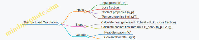
Example 3: Inverter Switching Frequency and Power Loss Estimation
Problem: An inverter switches at 10 kHz with a switching loss per transition of 0.5 mJ per switch per device. There are 6 switches in the inverter. Calculate the total switching losses.
Step 1: Calculate switching events per second per device
Switching frequency = 10,000 Hz
Step 2: Calculate switching loss per device per second
\[ P_{switch,device} = 0.5 \times 10^{-3} \times 10,000 = 5 \text{ W} \]
Step 3: Calculate total switching loss
\[ P_{switch,total} = 5 \times 6 = 30 \text{ W} \]
Result: The inverter dissipates 30 W as switching losses at 10 kHz.
Mind Map: Inverter Switching Loss Calculation
Example 4: Battery Energy Requirement for a Flight Segment
Problem: An electric aircraft requires 50 kW of propulsion power for 30 minutes. Calculate the minimum battery capacity in kilowatt-hours (kWh) and ampere-hours (Ah) assuming a 400 V battery system and 90% battery efficiency.
Step 1: Calculate energy required (accounting for efficiency)
\[ E_{required} = \frac{P \times t}{\eta} = \frac{50 \times 0.5}{0.9} = 27.78 \text{ kWh} \]
Step 2: Calculate battery capacity in Ah
\[ Q = \frac{E_{required} \times 1000}{V} = \frac{27,780}{400} = 69.45 \text{ Ah} \]
Result: The battery must supply at least 27.8 kWh or 69.5 Ah at 400 V to meet the flight segment power demand.
Mind Map: Battery Capacity Calculation

Example 5: Calculating Cooling Channel Flow Velocity
Problem: A liquid cooling channel has a cross-sectional area of 1 cm². The coolant flow rate is 0.05 kg/s, and the coolant density is 1000 kg/m³. Calculate the flow velocity in the channel.
Step 1: Convert area to m²
\[ A = 1 \text{ cm}^2 = 1 \times 10^{-4} \text{ m}^2 \]
Step 2: Calculate volumetric flow rate
\[ Q = \frac{\dot{m}}{\rho} = \frac{0.05}{1000} = 5 \times 10^{-5} \text{ m}^3/\text{s} \]
Step 3: Calculate velocity
\[ v = \frac{Q}{A} = \frac{5 \times 10^{-5}}{1 \times 10^{-4}} = 0.5 \text{ m/s} \]
Result: The coolant flows at 0.5 m/s through the channel.
Mind Map: Cooling Channel Flow Velocity
These examples cover core calculations encountered in electric aircraft propulsion design. They provide a foundation for understanding how electrical, mechanical, and thermal parameters interact. The mind maps help keep the process organized and transparent.
12.5 Reference Standards and Guidelines
Electric aircraft propulsion systems operate within a tightly regulated environment. Understanding and applying the relevant standards ensures safety, reliability, and certification compliance. This section summarizes key standards and guidelines relevant to high power density motors, inverters, and thermal management in electric aviation propulsion.
Key Standards Overview
-
RTCA DO-160: Environmental Conditions and Test Procedures for Airborne Equipment. This standard defines environmental testing requirements such as temperature, vibration, and electromagnetic interference (EMI) that propulsion components must withstand.
-
SAE ARP 5416: Guidelines for Electrical Wiring Interconnect Systems (EWIS) in Aircraft. It covers wiring practices critical for high-current propulsion systems.
-
MIL-STD-810: Environmental Engineering Considerations and Laboratory Tests. Though military-focused, it provides valuable test methods for temperature, shock, and humidity relevant to propulsion hardware.
-
IEC 60034: Rotating Electrical Machines. This international standard covers motor design, testing, and performance evaluation.
-
RTCA DO-254: Design Assurance Guidance for Airborne Electronic Hardware. Applies to the design and verification of electronic components like inverters.
-
AS9100: Quality Management Systems for Aviation, Space, and Defense. It governs quality processes for manufacturing and maintenance.
-
FAA AC 33.87-1: Aircraft Electrical Propulsion System Certification. Provides guidance for certifying electric propulsion systems.
-
ISO 14644: Cleanrooms and Associated Controlled Environments. Relevant for manufacturing sensitive components like power electronics.
Mind Map: Standards for Electric Aircraft Propulsion

Applying Standards: Examples
Example 1: Motor Thermal Testing per RTCA DO-160
A high power density motor must be tested for temperature extremes. DO-160 specifies temperature ranges and durations. For instance, the motor is subjected to -40°C to +85°C cycles while operating at rated load. This ensures motor materials and insulation withstand real flight conditions.
Example 2: EMI Compliance for Inverters
Inverters must meet EMI limits to avoid interference with avionics. DO-160 outlines conducted and radiated emission tests. A practical step is to use shielded cables and EMI filters, then verify emissions with a spectrum analyzer during full load operation.
Example 3: Wiring Installation per SAE ARP 5416
High current cables for propulsion systems require proper routing, securing, and protection. SAE ARP 5416 recommends separation from signal wires, use of fire-resistant insulation, and strain reliefs. An example is bundling power cables with heat-resistant sleeves and securing them with vibration-resistant clamps.
Example 4: Quality Management with AS9100
Manufacturers must document processes for design, production, and inspection. For example, traceability of motor winding materials and batch testing results are recorded to meet AS9100 requirements.
Mind Map: Certification Workflow for Electric Propulsion
Thermal Management Standards
Thermal management is critical for propulsion reliability. While no single standard covers all aspects, several guidelines apply:
-
RTCA DO-160 Section 4: Temperature and altitude testing for components.
-
IEC 60721: Classification of environmental conditions, useful for defining operating environments.
-
SAE ARP 1755: Guidelines for thermal design and analysis of aircraft electrical equipment.
Example: Designing a liquid cooling system for a motor involves applying SAE ARP 1755 recommendations on coolant flow rates and temperature limits, then verifying with thermal simulations and physical tests.
Summary
Standards and guidelines form the backbone of safe and reliable electric aircraft propulsion development. They cover environmental resilience, electrical safety, quality management, and certification procedures. Integrating these standards early in design and testing phases reduces costly redesigns and expedites certification.
Using the mind maps above can help organize compliance efforts and clarify relationships between different standards. Real-world examples demonstrate how these guidelines translate into practical engineering decisions.